6 Chapter 2 LITERATURE REVIEW Many researchers have considered various aspects of ground-borne vibration and its effects on buildings and their occupants, and several detailed studies have already been undertaken. Studies of the vibration sources include the work on vibration from surface vehicles by Hunt [57] and Ng [103], and that by Forrest [38] on underground railways. Studies of the vibration transmission path include Lo’s work on the vibration of piled foundations [76], while the work of Cryer [33] and Kraemer [66] considers noise and vibration in buildings. This literature review provides an overview of previous research in this field, with particular emphasis on the work of direct relevance to base-isolated buildings. The initial sections deal with the nature of the problem and the various methods of reducing its effects. Later sections introduce the details of base-isolated buildings and how they may be modelled theoretically. 2.1. The Problem of Ground-Borne Vibration Ground-borne vibration is essentially a man-made problem of the last 100 years or so, primarily due to the development of urban road and rail networks. Vibration generated by moving traffic propagates through the ground and into buildings, resulting in unacceptable levels of internal noise and vibration. This is illustrated in Figure 2.1, which shows a schematic diagram of Wellington Hospital in London. The building lies directly above two mainline railway tracks and within only a few metres of four underground railway tunnels and the main road. The complexity of the problem is clear: vibration from multiple sources propagates through and along
Transcript
6
Chapter 2
LITERATURE REVIEW
Many researchers have considered various aspects of ground-borne vibration and its effects on
buildings and their occupants, and several detailed studies have already been undertaken. Studies
of the vibration sources include the work on vibration from surface vehicles by Hunt [57] and Ng
[103], and that by Forrest [38] on underground railways. Studies of the vibration transmission
path include Lo’s work on the vibration of piled foundations [76], while the work of Cryer [33]
and Kraemer [66] considers noise and vibration in buildings. This literature review provides an
overview of previous research in this field, with particular emphasis on the work of direct
relevance to base-isolated buildings. The initial sections deal with the nature of the problem and
the various methods of reducing its effects. Later sections introduce the details of base-isolated
buildings and how they may be modelled theoretically.
2.1. The Problem of Ground-Borne Vibration
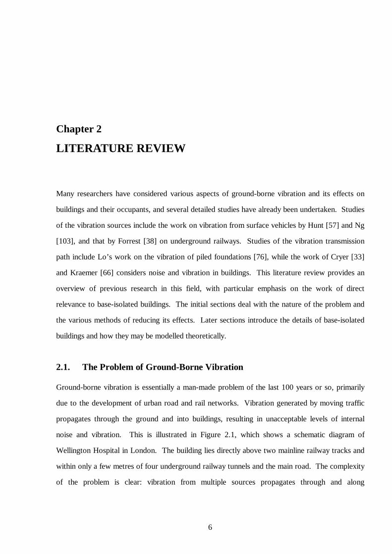
Ground-borne vibration is essentially a man-made problem of the last 100 years or so, primarily
due to the development of urban road and rail networks. Vibration generated by moving traffic
propagates through the ground and into buildings, resulting in unacceptable levels of internal
noise and vibration. This is illustrated in Figure 2.1, which shows a schematic diagram of
Wellington Hospital in London. The building lies directly above two mainline railway tracks and
within only a few metres of four underground railway tunnels and the main road. The complexity
of the problem is clear: vibration from multiple sources propagates through and along
CHAPTER 2. LITERATURE REVIEW 7
oo
o o
o o
the surface of the ground, interacting with buried objects on the way, before manifesting in the
building as internal noise and vibration.
Figure 2.1: Ground-borne vibration and its effects on buildings. Based on a diagram by Grootenhuis of Wellington Hospital, London [44]. To limit the internal noise and vibration due to the moving traffic, the building is base-isolated on rubber bearings located above the basement.
2.1.1. Sources of Ground-Borne Vibration
There are many sources of noise and vibration in buildings, such as wind, building services, the
closing of doors and the foot-falls of occupants. The focus in this dissertation is on the
transmission of ground-borne vibration into buildings. Seismic tremors are a natural source of
vibration but significant tremors are rare in the UK and they will not be considered in detail here.
Man-made sources, on the other hand, cause daily disturbance to large numbers of people and
they can have significant social and economic consequences. The three main sources are
described below and typical vibration levels and frequency ranges are identified. The significance
of these levels for buildings and their occupants are discussed in Sections 2.1.2 and 2.1.3.
CHAPTER 2. LITERATURE REVIEW 8
Construction Activity
Many mechanised construction activities lead to ground-borne vibration. Examples include
blasting, tunnelling, piling and vibratory compaction. Heavy industrial machines, such as drop
forges, are other related sources. Hiller et al. [52, 28] discuss a variety of such activities and
present field measurements of the resulting peak particle velocity of the ground: levels lie in the
range from 6 to 160 mm/s. The frequency content depends on the particular activity but is
typically below 100 Hz.
These levels of ground-borne vibration are not insignificant (see Section 2.1.2, Table 2.1) and,
as reported by the ORE D151 Committee [108], construction activities can cause disturbance to
building occupants and, in rare occasions, structural damage. However, the duration of the
disturbance is limited, as is the number of people affected. Much more significant as sources of
ground-borne vibration are roads and railways. The vibration amplitudes are comparatively small
but large numbers of people are exposed to an annoyance every day of the year. Even a perfect
vehicle travelling on a perfect road or railway would generate ground-borne vibration due to the
movement of its weight across the elastic surface of the ground. In practice, various
imperfections, in both the vehicle and the road or rail surface, lead to further vibration.
Roads
Several experimental studies have been conducted into the vibration generated by road vehicles;
see for example the ORE D151 report [108] and, specifically for road tunnels, the report by Bean
and Page [10]. In general, typical surface vibration levels are found to lie in the range from 0.1 to
1.0 mm/s.
Experimental work undertaken by Hunt [57] has revealed that the type of road surface has a
significant effect on the surface vibration spectra measured some distance from the road. The
frequencies associated with a Tarmac trunk road are largely confined to below 40 Hz, whereas a
concrete motorway led to significant frequency content up to at least 100 Hz. Spectra typically
contain two peaks below 20 Hz, which correspond to the body-bounce and wheel-hop
frequencies of the vehicles, as can be seen in the measurements by Hao et al. [46].
CHAPTER 2. LITERATURE REVIEW 9
There is evidence that the introduction of speed control measures on roads can result in
additional ground-borne vibration. An experimental study by Watts [135] into the effects of road
humps in residential areas concludes that perceptible levels of vibration can be experienced in
nearby buildings. However, complaints are only expected in extreme circumstances.
Railways
Railways carry heavy vehicles at high speed and often pass within a few metres of buildings and
their foundations. Consequently, they are generally regarded as the most significant source of
ground-borne vibration. Many experimental studies have been conducted into the vibration
generated by surface railways [108, 130], trams [72, 114] and underground railways [129, 91]. A
review paper by Heckl et al. [48] presents some general conclusions applicable to all types of
railway. Railway vibration is a low-frequency problem with peak vibration levels in the frequency
range from 40 to 80 Hz; the lower frequencies being especially associated with heavy freight
trains. A fall of 10 dB typically occurs by 100 Hz and a further 50 dB by 250 Hz. Measurements
indicate vibration levels in a similar range to road-generated vibration, that is, from 0.1 to 1.0
mm/s.
The two major sources of vibration reported by the ORE D151 Committee [108] are the
vertical bending of the axle and wheel-set, and the vertical bounce mode of the wheel-set on the
track. In addition, speed-dependent components may be identified such as that due to the wheels
passing each sleeper; typically observed by Grootenhuis [44] between 15 and 30 Hz. Vibration
associated with unsteady motion of vehicles – bounce, pitch and roll – lies below 10 Hz and the
energy level is usually low.
Although an increase in train speed can in fact reduce vibration levels, depending on the
proximity of the wheel-passing frequency to that of the wheel-track resonance, an increase in
speed generally leads to more vibration. In some cases it is possible for high-speed trains
travelling on soft ground to exceed the Rayleigh (surface) wave speed of the ground, or the
bending wave speed of the track. This generates unusually large vibration levels in a similar way
to the sonic boom generated by supersonic aircraft, as described by Krylov [68] and Madshus and
Kaynia [81].
CHAPTER 2. LITERATURE REVIEW 10
2.1.2. The Response of Buildings to Ground-Borne Vibration
Modern construction techniques tend to exacerbate the dynamic response of buildings by using
continuous light-weight structures such as steel frames and pre-stressed concrete. A prime
example is the new IMAX cinema, London, presented in Chapter 1. Such buildings have
inherently low damping, compared with older masonry structures, and larger span floors with
lower natural frequencies. Primary structural resonances typically occur in the frequency range
from 5 to 25 Hz and these can often coincide with a dominant frequency of the source, such as
the wheel-passing frequency of a nearby railway. In the past it has been noted that vibration due
to a passing train is of short duration and consequently any resonant response of a building is
short and limited by damping. However, Grootenhuis [45] shows that, given the damping
properties of modern construction materials, a typical train spends more than enough time passing
a building for a full state of resonance to be established. Thus modern construction methods tend
to result in buildings that are more susceptible to vibration within the frequency range of concern.
Structural vibration can be felt by a building’s occupants and is known as perceptible
vibration when the level is such that the comfort of the occupants is adversely affected.
Perceptible vibration occurs mainly in the frequency range from 10 to 60 Hz, as measured by
Kuppelwieser [71]. Structural vibration also radiates sound and this can be significant within the
audio frequency range, approximately 25 Hz and above. Re-radiated noise describes vibration,
originally radiated through the ground and into the building, which is then re-radiated as audible,
airborne noise. It is not a precise term but it is in common use and is considered preferable to the
alternatives of structure-borne or ground-borne noise.
An example of where re-radiated noise may be significant is the disturbance caused by an
underground train. This causes very little airborne noise to strike the facade of a building but the
ground-borne vibration it generates is transmitted through the foundation and into the building,
which then radiates noise. The result is an audible low-frequency ‘ rumble’ , even when the
vibration itself cannot be felt. The peak frequency-component of the noise does not necessarily
coincide with that of the vibration because it depends on the radiation efficiency of the structure
concerned. Kuppelwieser’s measurements suggest that it is most noticeable in the frequency
range from 50 to 125 Hz.
CHAPTER 2. LITERATURE REVIEW 11
The presence of vibration in a building can often lead to concerns over the possibility of
structural damage. However, there is little agreement on the vibration levels that can cause
damage due to the range of construction methods and materials used in buildings of different
ages. It is the inertia forces acting on a vibrating structure that have the potential to cause
damage. These forces are proportional to the acceleration levels and, since most buildings
respond less at higher frequencies, the potential to cause damage tends to decrease with
increasing frequency. This tendency has led to the definition of vibration intensity as a measure
of the damaging effects of structural vibration. Strictly, vibration intensity is defined for constant,
simply harmonic vibration and is equal to the square of the acceleration amplitude divided by the
frequency. In practice, vibration is rarely simply harmonic and the mean-square acceleration level
over a narrow frequency band is used. This is expressed in non-dimensional (decibel) units as
vibrars. Further details can be found in Mead [89].
Evidence cited by Mead suggests that the damaging effect of vibration is more dependent on
the inverse-square of the frequency, rather than the simple inverse relationship of vibration
intensity. This is equivalent to a dependence solely on the r.m.s. velocity, in this context referred
to as the vibration severity. This has some physical basis given the fact that particle velocity
indicates how energetic the vibration is and hence its ability to cause damage. A standard for the
evaluation and measurement of vibration in buildings is under preparation by the International
Standards Organisation; provisional damage criteria are given in Table 2.1. The velocity levels
represent the greatest of the three orthogonal linear velocities at prescribed points on the
structure. Note that Table 2.1 does not refer to the frequency of the vibration: it appears that the
velocity for a certain degree of damage is independent of frequency for the normal range of
ground-borne vibration and shock.
Typical ground-borne vibration levels due to road and rail traffic lie in the range from 0.1 to
1.0 mm/s, well below the criteria quoted above and even light damage, such as cracking of
plaster, is rare. The ORE D151 report [108] notes that, over a period of twenty-five years, not
one case of damage has been found to be directly attributable to vibration alone. It is generally
concluded that adverse human reaction occurs long before any damage takes place.
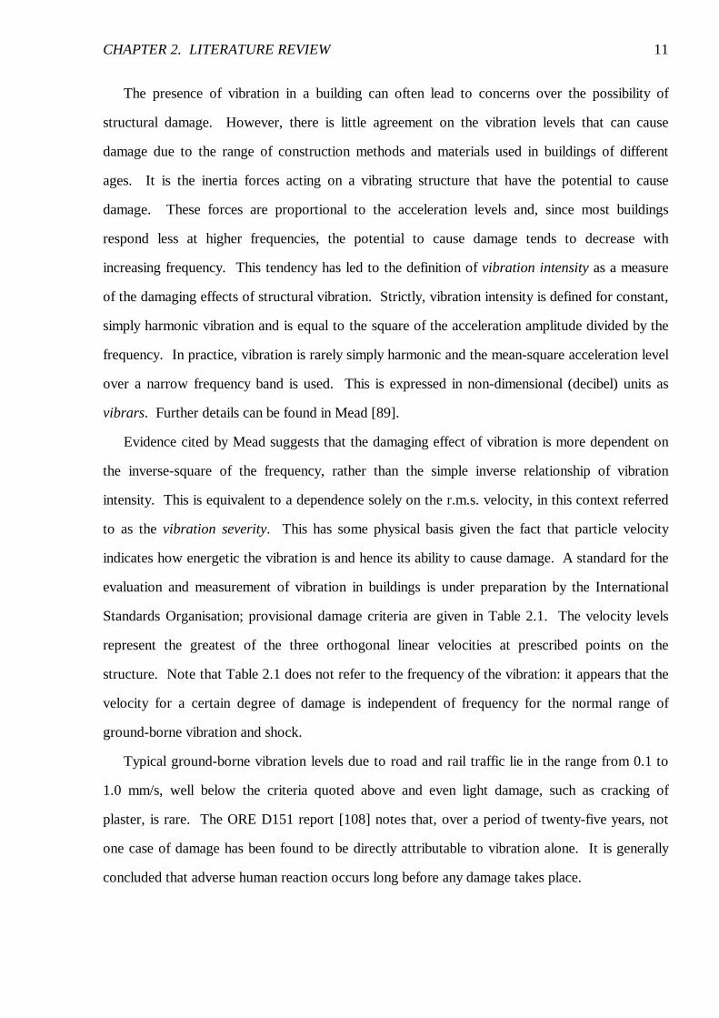
CHAPTER 2. LITERATURE REVIEW 12
Band R.m.s. velocity [mm/s] Effect
I <1.75 No damage
II 2.5-5.0 Damage very improbable
III 5.0-10.0 Damage not probable
IV >10.0 Damage possible; check the stresses!
Table 2.1: Provisional ISO building damage criteria (reproduced from Mead [89]).
An additional concern with specialist buildings, such as hospitals and research facilities, is that
they contain equipment that is highly sensitive to vibration. These vary greatly depending on the
equipment concerned and reference should be made to Mead [89] for criteria relating to
operational efficiency of certain facilities.
2.1.3. Human Response to Vibration and Re-Radiated Noise in Buildings
The level of vibration within a building that is considered acceptable is dependent upon many
factors, human nature being what it is. The threshold of perception provides the ultimate lower
limit: Mead [89] reports that, in an upright seated position, the whole body can perceive vertical
r.m.s. acceleration levels of the seat as low as 10 mm/s2 over the frequency range from 1 to
100 Hz. The corresponding mid-range velocity level is of the order of 1 mm/s, which may be
compared with the much higher levels in Table 2.1 that are required to cause structural damage.
In practice, the threshold of acceptability varies considerably from around the threshold of
perception to several times this value. It is dependent upon factors such as the duration and
nature of the vibration, the type of building and the activities of its occupants, and what the
occupants feel, hear and see. More subjective factors are also involved, such as what the
occupants expect to experience, concerns over structural damage, and whether they believe
anything could or would be done to improve the situation, such as reducing the vibration or
awarding compensation, if they were to complain.
The comprehensive book by Griffin [43] includes an assessment of building vibration together
with the diagram reproduced in Figure 2.2. This figure summarises the many factors that
influence human response and illustrates the difficulty in establishing criteria for acceptable levels
of vibration. The annoyance simply caused by the tinkling of glasses in a cabinet or the movement
CHAPTER 2. LITERATURE REVIEW 13
of a painting on a wall, all the more apparent due to reflections from the glass, may be the origin
of a complaint.
A number of standards aim to define acceptable vibration levels for buildings. In the UK, the
British Standard BS 6472 [20] and the International Standard ISO 2631-2 [59] are used
extensively. Griffin presents a review of both standards, together with the German DIN 4150-2
and American ANSI S3.29 standards on vibration in buildings.
A measure deemed appropriate for assessing transient vibration, such as that from a passing
train, is the vibration dose value (VDV). This is defined as the fourth root of the integral of the
fourth power of the frequency-weighted acceleration wa :
4/1
0
4 )(VDV��
����= �
=
T
t
w dtta (2.1)
with SI units of m/s1.75. The VDV provides a cumulative measure of the exposure to both
continuous and intermittent vibration, and also shocks, over the period T when vibration may be
experienced. It is considered preferable to r.m.s. measures because it accounts for the duration of
the vibration as well as its magnitude. Table 2.2 gives the approximate VDVs suggested in both
BS 6472 and ISO 2631-2 at which adverse reactions may be expected from people living and
working in buildings.
CHAPTER 2. LITERATURE REVIEW 14
Figure 2.2: The factors influencing human response to vibration in buildings (reproduced from Griffin [43]).
HEARING SEEINGFEELING
ExperienceExpectation
Identification of Source
AnnoyanceFear of Damage
Interference with ActivitiesInterference with Sleep
RESPONSENone
Adverse commentMake a complaint
Seek compensationProtest actionPsychological
stress
WARNINGS
PUBLICRELATIONS
AMBIENTCONDITIONS
other vibrationother noisetime of day
building areabuilding type
activity
AIRBORNENOISE
AIR OVER-PRESSURE
VIBRATIONOF:walls
ceilingsfloors
windowsornaments
VIBRATIONOF:
chairstablesbeds
floors
VIBRATIONOF:
windowsmirrorsplantslights
ornaments
DAMAGE:
cracksbreakages
SOURCE OFVIBRATION
location, frequency,magnitude, duration
GROUND RESPONSE
BUILDING RESPONSE
INTERNALFORCES
footfallsmachinery
doors
WIND
CHAPTER 2. LITERATURE REVIEW 15
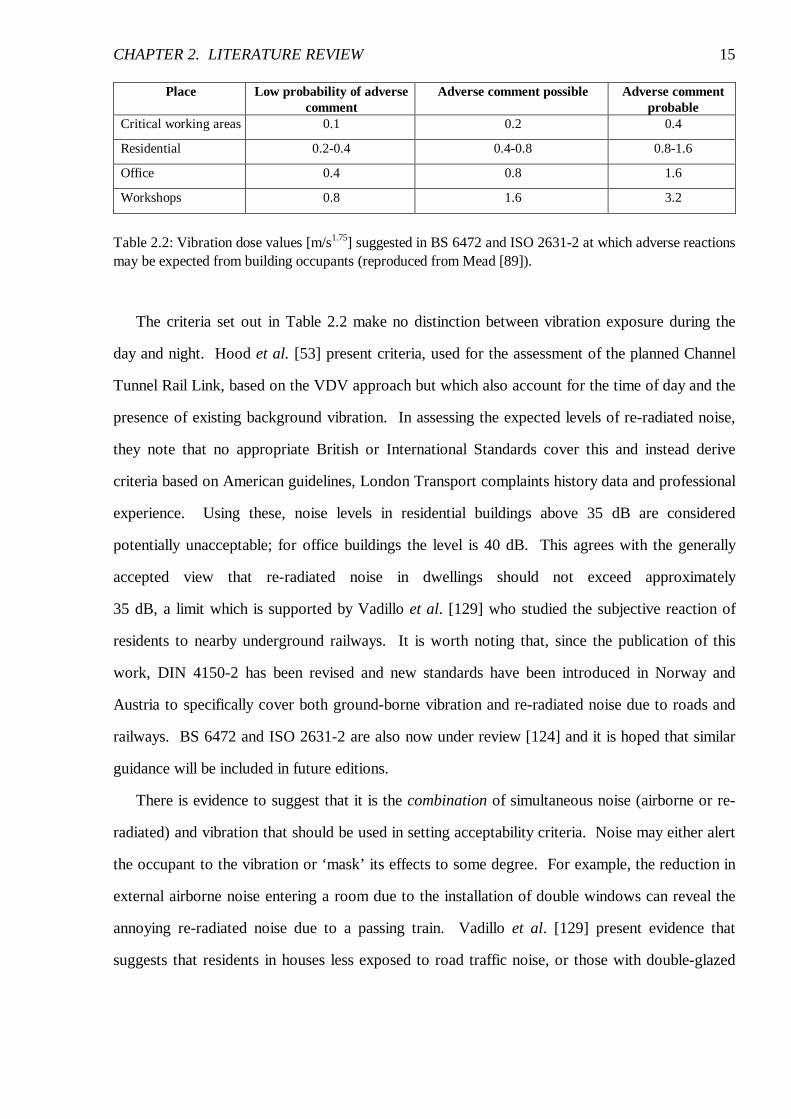
Place Low probability of adverse comment
Adverse comment possible Adverse comment probable
Critical working areas 0.1 0.2 0.4
Residential 0.2-0.4 0.4-0.8 0.8-1.6
Office 0.4 0.8 1.6
Workshops 0.8 1.6 3.2
Table 2.2: Vibration dose values [m/s1.75] suggested in BS 6472 and ISO 2631-2 at which adverse reactions may be expected from building occupants (reproduced from Mead [89]).
The criteria set out in Table 2.2 make no distinction between vibration exposure during the
day and night. Hood et al. [53] present criteria, used for the assessment of the planned Channel
Tunnel Rail Link, based on the VDV approach but which also account for the time of day and the
presence of existing background vibration. In assessing the expected levels of re-radiated noise,
they note that no appropriate British or International Standards cover this and instead derive
criteria based on American guidelines, London Transport complaints history data and professional
experience. Using these, noise levels in residential buildings above 35 dB are considered
potentially unacceptable; for office buildings the level is 40 dB. This agrees with the generally
accepted view that re-radiated noise in dwellings should not exceed approximately
35 dB, a limit which is supported by Vadillo et al. [129] who studied the subjective reaction of
residents to nearby underground railways. It is worth noting that, since the publication of this
work, DIN 4150-2 has been revised and new standards have been introduced in Norway and
Austria to specifically cover both ground-borne vibration and re-radiated noise due to roads and
railways. BS 6472 and ISO 2631-2 are also now under review [124] and it is hoped that similar
guidance will be included in future editions.
There is evidence to suggest that it is the combination of simultaneous noise (airborne or re-
radiated) and vibration that should be used in setting acceptability criteria. Noise may either alert
the occupant to the vibration or ‘mask’ its effects to some degree. For example, the reduction in
external airborne noise entering a room due to the installation of double windows can reveal the
annoying re-radiated noise due to a passing train. Vadillo et al. [129] present evidence that
suggests that residents in houses less exposed to road traffic noise, or those with double-glazed
CHAPTER 2. LITERATURE REVIEW 16
windows, are more annoyed by re-radiated noise due to underground trains. Attenuation
measures aimed at reducing noise may therefore increase the perception of vibration or vice versa.
Howarth and Griffin [54] describe an experimental study of the response of residents to
simultaneous noise and vibration from railways. Using a laboratory representation of a sitting
room mounted on a shake-table, subjects were exposed to various combinations of simulated
railway noise and vibration. Summing the individual effects of the noise and vibration, in terms of
the VDV and sound exposure level, was found to provide a more accurate measure of the total
annoyance caused by simultaneous noise and vibration than a method based on either noise or
vibration alone.
Human response to the effects of vibration in buildings is clearly a complex problem.
Research on the problem and attempts to define appropriate standards are certain to continue for
some time yet.
2.2. Methods of Reducing Ground-Borne Vibration
Section 2.1 has illustrated the difficulties in defining acceptable levels of noise and vibration in a
building, and different construction projects will in practice set different target levels. In general,
the aim must be to reduce the disturbance, whether perceptible vibration or re-radiated noise,
below the background level but within economic constraints and to the satisfaction of the end
user. This section reviews the various methods of achieving this.
2.2.1. Measures Taken at the Source
The most obvious action to take is to address the problem at its source and control the mechanism
by which ground-borne vibration is generated. In the case of road vehicles there is little evidence
of measures being implemented in practice, although work by Al-Hunaidi et al. [4] and Cole and
Cebon [25] suggests that significant reductions can be achieved by modifying vehicle suspension
systems.
The most common source of ground-borne vibration is railways and this is reflected in the
extensive efforts being made at reducing railway vibration. Track maintenance is the first
consideration, particularly the avoidance of track settlement and the deterioration of rail
CHAPTER 2. LITERATURE REVIEW 17
crossings. Rail grinding and wheel truing eliminates wheel flats and rail corrugations which
generate the higher frequency vibrations. More involved measures include the introduction of
continuously welded track and the modification of bogie designs. Wilson et al. [137] report that
reducing the suspension stiffness and unsprung mass significantly reduces the level of vibration
generated due to the bounce and wheel-hop modes of the vehicles. Some underground railways
use resilient wheels that significantly reduce vibration levels. However, this is not regarded as a
general solution because it requires special track and suffers from rapid tyre wear and high power
consumption. A review of special track constructions aimed at reducing vibration levels from
both surface and underground railways may be found in the ORE D151 report [107].
There is a number of rubber products used to reduce noise and vibration transmission into the
ground [100, 109, 110]; see Figure 2.3. These take the form of rubber pads between the rails,
base plates and sleepers.
rail pad
base-plate pad
sleeper pad
ballast mat
Floating slab track
Figure 2.3: The various rubber products used to reduce noise and vibration transmission from railways (courtesy of Getzner Werkstoffe GmbH, Bludenz, Austria).
Floating slab track (FST) is often used with underground railways and is generally regarded as
the most effective measure that can be taken with the track. This involves mounting the entire
track on a concrete foundation slab that rests on rubber bearings or steel springs. There are
numerous examples around the world [45, 137]. An equivalent to FST for conventional track is
CHAPTER 2. LITERATURE REVIEW 18
the use of thick rubber ‘ballast mats’ underneath the ballast. Proponents of FST often make
impressive claims regarding its performance, although recent work by Forrest [38] and Hunt [58]
suggests that the performance in underground railways can be severely limited by interactions
with the tunnel and the surrounding soil.
Reducing vibration transmission from the source is not always possible. For example, new
buildings are often constructed near existing railways and it is difficult and expensive to take
retrospective measures with either the track or the trains. In these cases measures are restricted
to the transmission path and the buildings themselves.
2.2.2. Modification of the Transmission Path
Modification of the transmission path, either through or on the surface of the ground, is possible
but often difficult to implement in practice. One option available is to construct deep trenches or
underground ‘wave barriers’ to impede the transmission of surface vibration. Lang [72] describes
experimental testing of trenches, filled with either ballast or mineral wool, which were found to
reduce tram vibration with some success. Yang and Hung [141] consider the effectiveness of
wave barriers located close to railways using a two-dimensional finite-element model representing
the cross-section of the railway, barrier and soil. They conclude that the effectiveness of such
barriers is largely dependent on their dimensions relative to the wavelength of the vibration. This
represents the generally held view that wave barriers and trenches are only of use if they can be
constructed to be at least as deep as the longest wavelength present, which is typically of the
order of 10 m but can be as great as 100 m. In addition, such measures are limited to surface
waves only: the ground generally becomes stiffer with depth and this can lead to diffraction of
body waves around the barriers.
An alternative measure is the Wave Impedance Block (WIB), a stiff layer introduced below a
surface vibration source to shield nearby buildings from the vibration. Both theoretical [123, 111,
122] and experimental [37] studies conclude that WIBs have the potential to help reduce vibration
transmission, although more work is required to develop practical cost-effective designs.
CHAPTER 2. LITERATURE REVIEW 19
A possible measure noted by Wilson et al. [137] for underground railways is the use of extra-
heavy tunnel structures, to reduce radiated vibration levels, located at increased depth. Again,
this is not straightforward to implement in practice.
2.2.3. Measures Taken at the Building
Some methods of reducing the effects of ground-borne vibration in buildings may be
straightforward to implement. Examples include avoiding furniture designs that resonate at the
frequencies present and moving sensitive equipment near to walls, away from the centre of the
supporting floor to a region where vibration levels are likely to be lower. If the problem is one of
re-radiated noise, the level of background noise may be increased to act as a mask.
More costly measures involve modifications to the building structure. Damping treatments
may be applied to resonant floors or walls, or incorporated into the supporting structure.
Vibration neutralizers (dynamic absorbers) may be installed at strategic points on the structure
and local stiffening may be undertaken to move structural resonances away from the excitation
frequency. When considering a new building, Manning [85] claims that it is invariably possible to
design a structure with vibration levels within the BS 6472 Category 4 curve [20] by adjusting
floor natural frequencies, using transfer structures as ‘springs’ and separating the building from
adjacent ‘source structures’ such as railway structures. This usually reduces the problem to one
of re-radiated noise.
In some cases, very low levels of noise and vibration may be required but only in particular
areas of a building. In these cases floating floors or a ‘room within a room’ may be required. An
example of the latter is a recording studio, constructed as a box mounted on isolation bearings
thereby isolating it from the rest of the building structure [51].
In many cases the ground vibration levels are considered large enough to justify the base
isolation of a building, that is, the building is designed with vibration isolation bearings between
the building and its foundation. Base isolation is not a new concept: Waller [134] notes that lead-
asbestos bearings were developed for some buildings in Manhattan in the 1930s as a means of
reducing an ‘audible hum’ transmitted through the rock on which the buildings were founded.
The first example of a base-isolated building in the UK is Albany Court, a block of flats
CHAPTER 2. LITERATURE REVIEW 20
constructed on rubber bearings over St James’ Park Station, London in 1965; see Figure 2.4.
Since then, numerous building projects have been undertaken on sites previously deemed
unacceptable due to high levels of ground-borne vibration and examples may be found in all
classes of building: residential buildings, office towers, concert halls, cinemas and hospitals.
Sharif [119] lists the fifty-five major base-isolated buildings in the UK.
Figure 2.4: The first example of a base-isolated building in the UK is Albany Court, a block of flats constructed on rubber bearings over St James’ Park Station, London in 1965 (reproduced from Waller [134]).
2.3. The Design of Base-Isolation Systems for Buildings
In the past, many different types of isolation bearing have been suggested and tried for buildings,
including cork, felt, lead-asbestos and neoprene-asbestos. The choice for modern buildings
essentially lies between laminated rubber bearings and steel helical springs. This section considers
this choice and other design issues in more detail.
2.3.1. The Decision to Base-Isolate and its Implications
The decision on whether or not to base-isolate a building is usually based on a series of vibration
measurements, usually r.m.s. velocity levels because these can be directly compared with vibration
CHAPTER 2. LITERATURE REVIEW 21
acceptance criteria and estimates can readily be made of re-radiated noise levels; see Manning
[85] and Grootenhuis [45]. Measurements may be made either at the site in question, prior to any
construction work, or on a similar building to the one being designed. The data collected are then
usually analysed with the help of empirical, and sometimes theoretical, models.
‘Green field’ measurements, made prior to any construction work, often provide the only
means of assessing the viability of a building project near to an existing source of vibration.
However, from these it is very difficult to predict the response of the completed building. Any
site measurement is a measure of the response of the measurement point to the dynamic force
input of the source and is not an absolute measure of source strength. For example, the
construction of the building’s foundation is likely to significantly alter the ground vibration field,
even before the building itself is constructed.
Ultimately, the decision on base isolation is one of cost and perceived benefit. With the
majority of the rubber-isolated buildings discussed by Crockett [32], the cost of isolation was
between 2 and 2.5 % of the total cost, although the total range was between 0.75 and 4 %. The
spring-isolation of the Le Corum concert hall in Montpellier, France cost 1.5 % [26] while that of
an office building in Munich cost 3 % [56]. These extra costs are relatively low given that they
are usually offset by the ability to build on an undesirable (due to the high levels of ground-borne
vibration) and therefore low-cost site.
There are practical design implications, not normally associated with a typical building project,
which must be addressed once the requirement for base isolation has been established. Some of
these are discussed by Crockett [32] and Moss [97]. A major implication is the reduction in
structural stiffness and overall stability due to mounting the building on isolation bearings. Many
tall buildings are constructed of floor slabs supported on columns and derive their stiffness against
wind excitation from a service tower or lift shaft. Once the building is mounted on isolation
bearings the stiffness of the structure is often no longer adequate and additional stiffening is
required. Additional horizontal stability may be provided by sets of horizontal bearings or rubber-
sleeved dowel pins. The latter pass through the vertical bearings and are cast at each end into the
foundation and respective building column. Alternatively, the isolation bearings may be set at an
angle to provide both vertical and horizontal restraint.
CHAPTER 2. LITERATURE REVIEW 22
Additional consideration must be given to settlement of the building on its bearings, either
during construction or subsequently through creep in the bearings, fire proofing of the bearings
and designing failsafe measures for the unlikely event of a collapsed bearing. Care must also be
taken not to ‘bridge’ the isolation by, for example, staircases, building services, construction
debris or acoustic coupling.
Although seismic isolation systems may be installed in existing buildings, no examples have
been found of retrospective isolation against man-made vibrations. This is thought to be due to
the high cost of the structural modifications involved.
2.3.2. Generic Design Principles
This dissertation is concerned with base-isolated buildings and usually designs do indeed locate
the isolation bearings at the base of the building, such as on the pile caps or at basement level. In
principle it is possible to locate the bearings higher up the structure and isolate only the upper
floors. However, theoretical evidence presented by Cryer [33] indicates that this is less effective
due to amplification of the ground vibration by resonances of the unisolated structure below the
bearings.
It was noted in Section 2.1.1 that seismic tremors are an obvious natural source of ground-
borne vibration and often, when discussing base isolation, it is assumed that isolation against
earthquakes is being considered. The design of seismic isolation systems is quite different from
those being considered here. Typical earthquakes cover the frequency range from 0.1 to 10 Hz,
which includes the major horizontal modes of buildings. Consequently, an earthquake results
primarily in low-frequency ‘swaying’ of buildings and the amplitudes can be large; the vertical
component is potentially less damaging as structures are inherently stiff in this direction. Seismic
isolation systems are therefore designed with a stiffness that is high vertically but low horizontally,
thereby reducing the natural sway frequency and the seismic response of the building. The most
common designs are passive and use either sliding bearings or laminated rubber bearings, often
combined with some form of mechanical damper to dissipate energy. Active methods based on
externally-powered actuators do exist but they are expensive and require maintenance. Seismic
CHAPTER 2. LITERATURE REVIEW 23
isolation is now a well-developed field in itself and will not be considered further here; see Naeim
and Kelly [99] for further details.
The higher frequency content and lower amplitudes of man-made vibrations require a different
design approach to seismic isolation systems. Although an outline International Standard has
been proposed [61], no standards currently exist specifically governing the design of base-isolated
buildings. Instead, designs are based on past experience and the requirements of the particular
project.
Usually only the vertical direction is explicitly considered, although ground vibration
amplitudes in the horizontal and vertical directions may be found to be comparable, as reported by
Waller [134]. The horizontal component of ground motion is, in general, neglected on the
assumption that the building’s inherent flexibility in this direction provides sufficient isolation.
Whether this is a reasonable assumption or not is currently open to debate.
Base isolation systems are principally defined in terms of their isolation frequency. This is the
frequency of vertical oscillation of the building assuming it behaves as a rigid mass on a spring;
see Appendix A. Typical isolation frequencies lie in the range from 5 to 15 Hz, and the lower the
frequency the more effective the isolation is expected to be. Note that isolation frequencies
should be quoted with care: the stiffness used should be the dynamic stiffness of the bearings,
which can depend on several factors such as excitation frequency and static load. Allowance
should also be made for secondary stiffnesses. For example, Waller [134] notes that seals
between Albany Court and the adjacent building, the ground, stairs, etc. represented 20 % of the
total bearing stiffness. The mass of the building should be based on the ‘unfactored’ dead load of
the building, including allowances for furniture, occupants and equipment.
The level of inherent damping offered by the bearings is also often quoted as an important
design parameter. Base isolation relies on vibration isolation rather than energy dissipation, the
basic requirement being a low dynamic stiffness. For maximum isolation, therefore, current
designs are based on the inherent damping being as low as possible, provided that sufficient is
present to control the rigid-body resonances of the building on the bearings and any internal
resonances of the bearings themselves. Despite this, the sensitivity of the overall isolation
performance to changes in bearing damping, and isolation frequency, is currently uncertain.
CHAPTER 2. LITERATURE REVIEW 24
As mentioned in Section 2.2.3, the choice of isolation bearings for modern buildings
essentially lies between laminated rubber bearings and steel helical springs. These will now be
considered in more detail.
2.3.3. Rubber Bearings for Base Isolation
Bridges were one of the first types of structure to be mounted on rubber bearings. Stevenson
[120] describes the use of natural rubber bearings on the Flinders Street railway viaduct in
Melbourne, Australia as a means of reducing noise and vibration. The structure was completed in
1891 and, after a century’s service, there is no evidence of deterioration of the bearings, the bulk
rubber being protected against oxidation and ozone attack by its oxidised surface layer.
The widespread introduction of rubber bridge bearings in the 1950s provided valuable
experience that eventually led to their introduction in buildings with the construction of Albany
Court in 1965. Since then, rubber bearings, rather than steel springs, have been popular in the
UK. Recent examples include Eland House, London [119] and Glasgow Concert Hall; see Figure
2.5. The bearings are available in two different types: either carbon-loaded natural rubber,
reinforced and stiffened by laminating with steel plates, or synthetic rubber made more flexible by
loading with cork particles and reinforced with layers of woven cloth.
Figure 2.5: One of the natural rubber bearings isolating Glasgow Concert Hall (courtesy of Silvertown UK Ltd, Burton-upon-Trent, UK). The bearings are located in the basement on top of concrete columns that support the building.
A major design requirement for rubber bearings is a high static load-carrying capacity in
compression. This prevents excessive deflection of the building during construction, although
CHAPTER 2. LITERATURE REVIEW 25
some flexibility is desirable to cope with construction tolerances and distribute the load between
bearings. Thinner layers allow a bearing to carry a higher static load but this increases its dynamic
stiffness.
Muhr [98] discusses in detail the design of rubber bearings and directly challenges the
commonly held view that they are impractical for low frequency base-isolation. For a given mass
of building, the lower the isolation frequency the larger must be the bearings. While this does
have a cost penalty, there is no practical reason why a laminated rubber bearing cannot achieve an
isolation frequency of around 4 Hz.
The level of inherent damping of rubber bearings is at least one order of magnitude greater
than that of steel springs, and up to three orders greater depending on the formulation [98]. A
compound may easily be formulated to have a particular level of damping and there is no need for
the auxiliary damper units often used with steel springs. Synthetic rubber has a higher level of
inherent damping than natural rubber, although the latter has a lower dynamic/static stiffness ratio
and better creep properties [134].
Uneven or excessive creep in the rubber bearings could cause differential settlement and
structural damage, and this was a major concern with the design of Albany Court. However,
Stevenson [120] reports that after 15 years the amount of creep is close to that predicted and is
not expected to exceed 6 mm after 100 years. It is also reported that the general condition of the
bearings appears to be excellent. Despite Huffmann’s claims [56] that rubber bearings tend to
stiffen with age, resulting in deterioration in the isolation efficiency with time, there is little
experimental evidence to support this. Measurements made by Alder and Fuller [3] on the rubber
bearings of Pelham Bridge in Lincoln, UK, and those reported by the ORE D151 Committee
[109] on various rubber-based anti-vibration systems for railways, show negligible deterioration in
the elastic properties after decades in service.
Rubber is a highly non-linear material and the dynamic properties of rubber bearings depend
on many factors: static load and frequency of dynamic loading, the stiffness increasing with both
of these; strain amplitude; operating temperature; and the age and history of the bearing [75]. For
most applications, Moss [96] claims that the properties are adequately described by the static
load-deflection relationships in compression and shear, the long-term creep behaviour under
CHAPTER 2. LITERATURE REVIEW 26
constant static load, and the dynamic modulus and damping factor at different frequencies and
amplitudes.
The only standard of direct relevance to base isolation, the British Standard
BS 6177 [19], provides guidance on the use of rubber isolation bearings for buildings. Rubber is
virtually incompressible and the bearing stiffness in compression is controlled by the rubber’s
behaviour in shear and its ability to bulge sideways. BS 6177 defines the shape factor of a
bearing as the ratio of the loaded area to that free to bulge. This has a large effect on the
bearing’s isolation frequency, with a smaller plan area giving a lower isolation frequency for the
same thickness and loading. It is therefore usual to use large numbers of small bearings rather
than a few large bearings.
2.3.4. Steel Springs for Base Isolation
Helical steel springs have been used extensively in continental Europe for the base isolation of
buildings, including isolation against foundation subsidence such as in the German coal mining
areas. Their use in the UK has not been as extensive as the rubber alternative; indeed, as recently
as 1985, springs were considered too expensive, lacking in inherent damping and the number
required too impractical [32]. These concerns are no longer valid, although steel springs are, in
general, a more expensive option than rubber bearings. Sharif [119] gives the approximate cost
of a spring isolation as £33.00 per tonne of building, compared with £10.60 and £6.70 for natural
and synthetic rubber bearings respectively. Recent UK examples of spring-mounted buildings are
the IMAX cinema, London [49] and the Bridgewater Concert Hall, Birmingham [5].
There are two main advantages claimed by the manufacturers of steel springs over rubber
bearings: lower isolation frequencies and the benefits of pre-compression. Huffmann [56] refers
to springs offering isolation frequencies as low as around 2 Hz, although the lowest quoted as
being achieved in practice is a 3 Hz isolation for an office building in Munich.
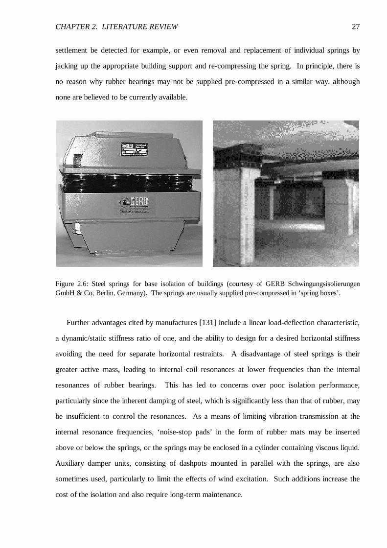
Pre-compression is achieved by supplying the springs in ‘spring boxes’, pre-compressed
between two steel plates to typically 80 % of the expected dead load [5]; see Figure 2.6. This has
no effect on the isolation efficiency but it does limit the static deflection of the building during
construction. It also enables post-construction adjustment of the springs, should differential
CHAPTER 2. LITERATURE REVIEW 27
settlement be detected for example, or even removal and replacement of individual springs by
jacking up the appropriate building support and re-compressing the spring. In principle, there is
no reason why rubber bearings may not be supplied pre-compressed in a similar way, although
none are believed to be currently available.
Figure 2.6: Steel springs for base isolation of buildings (courtesy of GERB Schwingungsisolierungen GmbH & Co, Berlin, Germany). The springs are usually supplied pre-compressed in ‘spring boxes’.
Further advantages cited by manufactures [131] include a linear load-deflection characteristic,
a dynamic/static stiffness ratio of one, and the ability to design for a desired horizontal stiffness
avoiding the need for separate horizontal restraints. A disadvantage of steel springs is their
greater active mass, leading to internal coil resonances at lower frequencies than the internal
resonances of rubber bearings. This has led to concerns over poor isolation performance,
particularly since the inherent damping of steel, which is significantly less than that of rubber, may
be insufficient to control the resonances. As a means of limiting vibration transmission at the
internal resonance frequencies, ‘noise-stop pads’ in the form of rubber mats may be inserted
above or below the springs, or the springs may be enclosed in a cylinder containing viscous liquid.
Auxiliary damper units, consisting of dashpots mounted in parallel with the springs, are also
sometimes used, particularly to limit the effects of wind excitation. Such additions increase the
cost of the isolation and also require long-term maintenance.
CHAPTER 2. LITERATURE REVIEW 28
2.4. Current Measures of Isolation Performance
No standard measure exists for assessing the performance of base isolation of buildings, although
three categories of measure are encountered in practice:
• green-field site predictions;
• predictions given a particular source;
• insertion gain.
The first two are measures of absolute performance while the third is a measure of insertion
performance. These are now considered in more detail, along with a discussion of vibrational
power flow.
2.4.1. Green-Field Site Predictions
The future occupants of a new building are interested in the absolute performance of the isolation,
that is, what they will experience in the completed building. Engineers may satisfy this by
predicting vibration levels within the isolated building given vibration data measured on the
‘green-field’ site prior to any construction work. This approach often forms the basis of a
decision on whether or not base-isolation is necessary, as in the case of the IMAX cinema,
London [49].
As discussed by Cryer [33], green-field site predictions require knowledge of the effects of the
building and its foundation on the ground vibration-field, as well as an understanding of the
dynamic behaviour of the building itself.
2.4.2. Predictions Given a Particular Source
Alternatively, occupants of an existing building may be interested in the vibration levels due to a
particular vibration source, such as a new railway. In this case the prediction is particularly
difficult to make because a detailed understanding of the entire vibration transmission path is
required. Examples of where this has been attempted include the empirical predictions by Hood
et al. [53], for the assessment of the planned Channel Tunnel Rail Link, and the theoretical
CHAPTER 2. LITERATURE REVIEW 29
predictions by Chua et al. [24] of vibration levels in an office block above an underground
railway. In the latter, the frequency range was limited to below 50 Hz and errors of up to 14 dB
were encountered when the predictions were compared with experimental measurements.
2.4.3. Insertion Performance
The client who pays for the additional cost of base isolation is interested in the insertion
performance, that is, the benefit of inserting isolation bearings beneath a building. It is also of
interest to the Engineer who wishes to evaluate alternative types of isolation bearing.
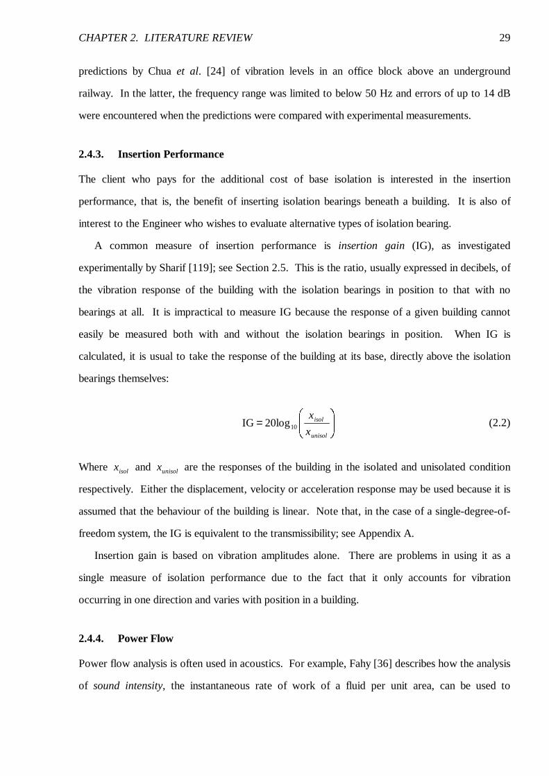
A common measure of insertion performance is insertion gain (IG), as investigated
experimentally by Sharif [119]; see Section 2.5. This is the ratio, usually expressed in decibels, of
the vibration response of the building with the isolation bearings in position to that with no
bearings at all. It is impractical to measure IG because the response of a given building cannot
easily be measured both with and without the isolation bearings in position. When IG is
calculated, it is usual to take the response of the building at its base, directly above the isolation
bearings themselves:
��������=
unisol
isol
x
x1020logIG (2.2)
Where isolx and unisolx are the responses of the building in the isolated and unisolated condition
respectively. Either the displacement, velocity or acceleration response may be used because it is
assumed that the behaviour of the building is linear. Note that, in the case of a single-degree-of-
freedom system, the IG is equivalent to the transmissibility; see Appendix A.
Insertion gain is based on vibration amplitudes alone. There are problems in using it as a
single measure of isolation performance due to the fact that it only accounts for vibration
occurring in one direction and varies with position in a building.
2.4.4. Power Flow
Power flow analysis is often used in acoustics. For example, Fahy [36] describes how the analysis
of sound intensity, the instantaneous rate of work of a fluid per unit area, can be used to
CHAPTER 2. LITERATURE REVIEW 30
investigate the characteristics of sound fields and sound sources. In a similar way, another way of
assessing structures is to consider the vibrational power flows within them.
Langley [73] discusses the theoretical analysis of power flow in beams and frameworks, and
illustrates how this is useful for identifying the dominant vibration transmission paths and
optimising the location of a vibration neutralizer. White [136] describes experimental techniques
for making measurements of power transmission in pipework and how these can be used to design
effective vibration control measures. In the context of building vibration, Gibbs and Moorhouse
[41, 95] discuss the importance of power flow in characterising the strength of vibration sources,
such as those associated with building services machinery. In particular, it is argued that the
minimisation of power flow from machines into supporting structures is the key to reducing
perceptible vibration in buildings.
2.5. Experimental Investigations into Base-Isolated Buildings
There is little doubt that base isolation is effective: enough evidence is presented by Henson and
Charles [49] in describing the success of the IMAX cinema, with what must be one of the most
demanding specifications yet. However, the precise nature of the isolation performance and the
benefits of certain design features, such as a low isolation frequency or a particular level of
damping, remain uncertain. The problem is that it is difficult to measure isolation performance
directly. In principle, a building may be jacked up and the bearings removed or alternatives tried
but this is difficult and expensive to achieve in practice and no reports of it have been found in the
literature. The closest attempt at achieving this is the recent experiment undertaken by Sharif
[119] using a test structure constructed on a concrete raft foundation above one of London’s
underground railway tunnels. The structure, designed as one of the ground floor rooms of a
residential house, was a reinforced concrete box, approximately 7 x 7 x 2 m, with openings for
doors and windows. Acceleration levels were measured on the floor of the structure in its
unisolated condition, resting on concrete blocks, and when isolated on three types of bearing:
steel springs, natural and synthetic rubber. In this way the IG of the bearings could be
determined. Five main conclusions may be drawn from the investigation:
CHAPTER 2. LITERATURE REVIEW 31
• for all three bearing types, the vertical rigid-body mode of the structure on the bearings is
clearly evident at the isolation frequencies;
• the resonant responses at the three isolation frequencies are similar, within 2 dB, despite
different levels of inherent damping in the bearings;
• the lower isolation frequency offered by the steel springs provides better isolation than the
rubber bearings – up to 20 dB based on the vibration measurements made;
• vibration modes of the structure significantly reduce the efficiency of the isolation – something
not predicted by simple theoretical models;
• inserting isolation bearings decouples the structure from its foundation and results in greater
foundation vibration than in the unisolated case due to the reduced constraint – the vibration
modes of the foundation then reduce the isolation efficiency.
These are important conclusions, although care must be taken when generalising to practical
base-isolated buildings given the small, relatively rigid test structure. Of immediate interest is the
final conclusion that highlights the inadequacy of one technique used to indicate isolation
performance. Measurements, such as those by Wagner [131] and Anderson [5], are often made
above and below the isolation bearings of a completed building to demonstrate lower vibration
levels above the bearings. This is not indicative of isolation performance because the
measurements concentrate on the forced response of only a small part of a complex structure. In
addition, as Sharif’s measurements show, the performance may be exaggerated by greater
vibration of the foundation than would otherwise exist beneath an unisolated building.
Cryer [33] describes a programme of measurements on a 12-storey rubber-isolated apartment
building at Gloucester Park, London. This is a large development close to several underground
railway lines and with parts directly above station platforms. Of particular interest are Cryer’s
measurements of total and direct transmissibility between the basement (below the isolation
bearings) and various floors within the completed building. The total transmissibility is the ratio
of the vibration amplitudes at the two measurement points and does not distinguish between
CHAPTER 2. LITERATURE REVIEW 32
vibration arriving at the upper measurement point via different paths (it is of interest to the
occupants who are not interested in where the vibration comes from). Direct transmissibility is
the same ratio but considers only vibration at the two points that is correlated, thereby giving a
measure of the importance of the particular input or transmission path.
If the isolated building behaved as a single-degree of freedom system, both transmissibilities
would be equal. The measurements clearly show that this is not the case and the building behaves
as a multiple-input flexible structure with a series of resonance frequencies. The 9 Hz isolation
frequency of the bearings is evident but the level of transmissibility is much less than that
predicted by simple theoretical models (see Section 2.6); at frequencies close to structural
resonances the transmissibility is large and sometimes greater than unity. It is worth noting that
these transmissibility measurements do not indicate isolation performance as no account is taken
of vibration levels in the building’s unisolated state.
Claims of impressive isolation performance should be viewed with caution. Commins et al.
[26] describe the design of the Le Corum concert hall in Montpellier, France, which is located
close to a surface railway. The difference, of up to 50 dB, between third-octave band vibration
levels measured in the nearly completed hall and an unisolated conference hall on the same site is
cited as evidence of effective isolation. However, when the details of the site are considered, it is
evident that the conference hall is smaller and much closer to the railway than the new concert
hall.
The use of scale models in a laboratory centrifuge, to simulate correctly the effects of gravity,
is a common technique for investigating the geotechnical and seismic behaviour of structures; see
for example the work of Madabhushi [79] and Cheney et al. [23]. Investigations into the
behaviour of model footings have also been conducted by Nii [104] using a model half-space. No
reports of experiments using physical models of base-isolated buildings have been have been
found in the literature. It is believed that this is largely due to the frequency range of interest,
which, for man-made ground-borne vibration would need to extend up to at least 100 Hz. This
corresponds to 1 kHz in a 1:10 scale model and good models of a building, its foundation and
isolation bearings would be difficult to produce.
CHAPTER 2. LITERATURE REVIEW 33
2.6. Modelling Base-Isolated Buildings
Since the construction of the first base-isolated buildings, various attempts have been made at
modelling their behaviour. This section reviews the two different available approaches, empirical
and theoretical, that have been used to model base-isolated buildings and those subject to ground-
borne vibration from roads and railways.
Models may be formulated in either the time or frequency domains. The former is often used
for the seismic analysis of structures where peak vibration levels due to a transient event are of
interest. Non-linear behaviour can also be treated in the time domain. When dealing with man-
made ground-borne vibration the problem may be treated as linear, given the low strain
amplitudes involved, and the response, particularly that due to railways, is of sufficient duration
that the frequency domain is the most appropriate. This and the next section therefore
concentrate on frequency-domain models. The range of models discussed is similar to that
currently being considered for incorporation into a proposed International Standard on predicting
ground-borne vibration due to railways in tunnels [61].
2.6.1. Empirical Models
Empirical models are usually based on octave or one-third octave band vibration measurements
made at existing sites. Statistical analysis is carried out on the data and a database compiled
which may then be used to make predictions for similar sites. Such models are widely used for
the prediction of noise and vibration levels in buildings.
Hood et al. [53] present two empirical models specifically for the assessment of trains in bored
tunnels, one for the prediction of vibration in buildings and the other for re-radiated noise. The
calculation procedures for both models are similar in that they each consist of three stages,
considering the source, propagation path and building response, and combine track-side data with
a series of factors or transfer functions derived from statistical analysis of a database of
measurements.
Kuppelwieser [71] presents a semi-empirical prediction model developed for the Swiss Federal
Railways. This is based on a step-by-step multiplication of track-side vibration data with a series
of transfer functions to obtain predictions of noise and vibration levels in buildings. The transfer
CHAPTER 2. LITERATURE REVIEW 34
functions account for the various stages in the propagation path from the rail to the building, as in
the models of Hood et al., but they may be determined from theoretical models chosen by the user
as well as by analysis of a database. Two further examples of semi-empirical models, based on a
combination of analytical techniques, laboratory tests and in-situ measurements, are due to Melke
[91] and Madshus et al. [80].
While empirical models can provide useful, as well as reasonably rapid, estimates of noise and
vibration levels once a database has been compiled, they do have significant limitations. It is very
difficult to compile a sufficiently comprehensive database, with a statistically significant set of
data, to cover all the possible combinations of source, transmission path, type of building, etc.
Databases are therefore rarely large enough to enable underlying physical behaviour to be
identified. In fact, ‘modular’ models, such as those reviewed, treat each part of the transmission
path separately and the various factors and transfer functions are assumed to be independent.
This approach does not represent the physical situation and cannot account for coupling between
various parts of the system, such as that due to interaction between the building and the ground.
In addition, the databases often remain commercially confidential to the organisations that
prepared them and two databases rarely share the same data structure.
2.6.2. Theoretical Models
Theoretical models rely on fundamental physical laws and some simplifying assumptions to
produce a series of equations. These are then solved either analytically or numerically.
Analytical Models
The simplest model of a base-isolated building is the standard single-degree-of-freedom (SDOF)
oscillator; see Appendix A. This represents the isolated building as a rigid mass supported on a
spring and some form of damping element to represent the isolation bearings. The model was
originally used by Waller [134] when describing Albany Court and is used extensively in the
design of isolation bearings for machines. This, together with its inherent simplicity, has probably
resulted in the model’s popularity: it is often used to illustrate the principle of base isolation by
CHAPTER 2. LITERATURE REVIEW 35
bearing manufactures [126] and is sometimes used to promote one bearing design over another
[56, 131].
Despite its popularity, the value of the SDOF model is extremely limited because it fails to
describe some of the major features of a building’s dynamic behaviour, in particular the flexibility
and damping properties of the building and the effects of its foundation. Even the relatively rigid
test structure investigated by Sharif (see Section 2.5) suffered from structural resonances and
foundation behaviour that significantly reduced the performance of its isolation.
The SDOF model may be improved by replacing the rigid mass with a flexible column.
Newland and Hunt [102] and Grootenhuis [44] use the analytical solutions for an elastic bar to
demonstrate that a typical building column has several natural frequencies below 200 Hz at which
the predicted level of isolation is significantly reduced. Swallow and Sharif consider two similar
models based on a lumped parameter model [121] and an elastic bar [119]. Additional masses
and springs are coupled to the bar to represent the connected floors and it is shown that this
reproduces some of the low-frequency behaviour observed with real building columns. Column
models may also be coupled to a simple foundation model to account for vibration radiation into
the ground [102].
The column model is still limited by its one-dimensional nature. It does not account for
flexural vibration and the fact that, in practice, buildings have multiple inputs at which the
vibration may or may not be correlated. The work of Cryer [33] takes the analytical models one
stage further by using the dynamic-stiffness method to model a two-dimensional portal-framed
building resting on a three-dimensional piled foundation. The dynamic-stiffness method accounts
for both the longitudinal and transverse behaviour of the columns and floors of the building, and
the foundation model, based on a series of Novak piles (see Section 2.7.2), accounts for the
interaction between the building and the ground. The computation time is minimised by treating
the building as infinitely long and using periodic structure theory [88]. Cryer’s model clearly
demonstrates the importance of including a representation of the foundation: a significant amount
of vibrational energy is radiated into the ground when the building is subject to a point excitation
at one of the pile caps. While the model goes some way to accounting for the behaviour of a
CHAPTER 2. LITERATURE REVIEW 36
piled foundation, only the vertical pile behaviour is accounted for and no attempt is made to
model interaction between neighbouring piles through wave propagation in the surrounding soil.
Balendra et al. [7] use a semi-analytical model to predict the response of buildings to
underground railways. The two-dimensional plain-strain model comprises a rigid tunnel in an
elastic half-space with a rigid embedded footing coupled to a lumped mass to represent the
building. The rigid-body representations of the tunnel and the building are considered major
limitations of this model.
Numerical Models
The finite-element method (FEM) [142, 143] is now the most widely used numerical technique
for engineering analysis and it has naturally been used to model vibration of buildings. Manning
[85] describes how, for design purposes, building vibration levels are estimated using simple FEM
models given a digitised copy of measured railway vibration which is applied to the base of the
model. A similar approach is used by Hao et al. [46] to predict vibration due to road traffic.
Both approaches are limited as they ignore the presence of a foundation.
Chua et al. [24] use a FEM model to predict vibration levels in a four-storey office block
directly above four underground railway tunnels. The foundation is represented as a portion of
the ground with a non-reflecting boundary to reduce unwanted wave reflections (see Section
2.7.1). The model is two-dimensional, assuming plain-strain conditions, and the building is
treated as symmetrical to reduce the number if elements required. Results are compared with
experimental measurements over the frequency range from 6 to 50 Hz and, although the trend
with frequency is correct, errors of up to 14 dB exist above 15 Hz.
It is fair to conclude that the FEM requires considerable computing power to achieve
reasonable results, even with relatively simple two-dimensional models. Results are usually
obtained using modal analysis and are therefore inaccurate at higher frequencies unless large
numbers of elements are used.
Thornely-Taylor [125] uses the finite-difference method (FDM) [132] to model the tunnel-
soil-building system in the time-domain based on the equations governing Euler beams, thin plates
and elastic solids. Again the model is computationally expensive despite being two-dimensional.
CHAPTER 2. LITERATURE REVIEW 37
Statistical energy analysis (SEA) [140] is another major numerical technique for analysing
structural vibration. Craik [29] describes in detail how the method may be effectively applied,
within the audio frequency range, to modelling noise and vibration transmission through buildings.
Trochides [128] uses a SEA approach to model building vibration from an underground tunnel.
Reasonable agreement is achieved between predicted levels and those of a simple 1:10 scale
model over the frequency range from 250 to 4000 Hz. As these examples demonstrate, the
success of SEA relies on a structure having sufficient modal density such that individual modes
are unimportant and vibration levels in various parts of the structure may be described in terms of
the average vibrational energy. The problem with applying SEA to ground-borne vibration is that
the frequency range of interest extends down to only a few hertz where modal behaviour is
important. Despite its computational efficiency, SEA is therefore considered inappropriate for
studying base-isolated buildings.
It is clear from the literature that, where the ground has been included in building models, a
three-dimensional representation is rare. Two-dimensional models are preferred for their
simplicity and the need, especially when using the FEM, to restrict computation times. The
disadvantage of this is that such models assume the system to be invariant in the anti-plane
direction and this significantly limits the ability to correctly model wave propagation. For
example, vibration that in practice may propagate on spherical wavefronts is constrained to
cylindrical wavefronts and therefore attenuates less rapidly with distance, foundations such as
piles are represented as infinitely long barriers around which waves can no longer diffract and
point excitation becomes a coherent line source. It is therefore considered important to
investigate further the methods available for modelling the three-dimensional nature of wave
propagation in the ground.
2.7. Modelling the Ground and Foundations
This section summarises the nature of wave propagation in the ground and reviews the methods
available for modelling this and the dynamic behaviour of foundations.
CHAPTER 2. LITERATURE REVIEW 38
2.7.1. Wave Propagation
The fundamental behaviour of the ground may be modelled by a homogeneous isotropic linear-
elastic half-space, that is, a solid bounded only by the plane formed by its free surface. Such a
solid can support two types of body wave: primary and secondary waves [42, 12]. Primary or
P-waves, also known as dilatational, compression or irrotational waves, result in particle motion
parallel to the direction of propagation; secondary or S-waves, also known as distortional, shear
or equivoluminal waves, result in particle motion perpendicular to the direction of propagation
and may be polarised in a particular direction.
A third wave-type exists due to the presence of the free surface. This is known as the
Rayleigh wave, after Lord Rayleigh who first discovered them [116]. Rayleigh waves are
essentially surface waves, with the majority of the motion lying within one wavelength of the free
surface and describing a retrograde ellipse in the vertical plane.
All three wave-types are non-dispersive and propagate at speeds dependent solely on the
elastic properties of the half-space. P-waves travel the fastest, followed by S-waves and then
Rayleigh waves. In general, body waves are generated by both buried and surface vibration
sources, while Rayleigh waves are generated by surface sources or whenever P-waves or
vertically polarised S-waves occur in the neighbourhood of the free surface. The partition of
energy between the three wave-types depends strongly on the size of the source relative to the
wavelengths generated. Wolf [138] shows that, for a surface source, if it is localised to an area
with dimensions small compared to the S-wavelength, Rayleigh waves transmit approximately half
of the energy with the remainder going largely into S-waves. If, on the other hand, the source is
large, the majority of the energy is transmitted by body waves. In practice, a notable source of
body waves is an underground railway whereas notable sources of Rayleigh waves are surface
vehicles or piling operations.
Waves are attenuated by two mechanisms: radiation damping and material damping. The
former is sometimes referred to as geometric damping and is due to the geometric spreading of
wavefronts as they propagate away from a source, thereby dispersing energy over an increasing
area. This attenuation is independent of frequency but affects Rayleigh waves the least because
they are essentially confined to the surface. Material damping describes the frictional energy
CHAPTER 2. LITERATURE REVIEW 39
dissipation that occurs during the passage of a wave when the ground undergoes cyclic shear or
compression, and higher frequencies are attenuated the most over a given distance. The
behaviour of foundations is generally dominated by radiation damping and, as reported by Prange
[113], foundation models are often found to be insensitive to the level of material damping.
A uniform half-space is an idealisation and, in practice, the ground is often much more
complex. In particular, soil density often increases with depth, leading to refraction of waves, and
different soil strata may be present that result in multiple reflections and refractions of waves at
their interfaces. The latter has a dispersing effect and wave speeds no longer depend solely on the
elastic properties of the soil but also on frequency. Further complications arise due to
inhomogeneous soils. While these are addressed in the literature, see for example Auersch [6]
and Degrande et al. [34], they are considered beyond the scope of this review.
Closed-form analytical solutions to problems of ground-borne wave propagation are rarely
possible and numerical techniques are usually used instead; in particular the FEM and the
boundary-element method (BEM) [17, 35]. When modelling the semi-infinite extent of the
ground, domain methods, such as the FEM, suffer from a fundamental problem. The element
mesh should extend towards infinity but in practice must be curtailed at a certain distance. The
resulting artificial boundary leads to spurious wave reflections that can distort the solution.
Simple solutions to this problem are to use large models – which require long computation times
– or specify artificially high material damping such that the waves have decayed sufficiently before
reaching the boundary; see for example Mohammad and Krylov [94]. In general this is
unsatisfactory and a more sophisticated approach is required in the form of non-reflecting
boundaries.
A technique explained in detail by Bettess [14] and adopted by some of the commercial FEM
codes, such as ABAQUS, is to use conventional finite elements in the interior of the model but
form the boundary from infinite elements. In the frequency domain these take the form of a finite
element based on a shape function that includes the outgoing waveform. Radiation to infinity is
then accounted for by either multiplying the shape function by a decay function, such as a
decaying exponential, or by mapping the element onto an infinite domain. However, no existing
CHAPTER 2. LITERATURE REVIEW 40
infinite elements for elastic waves are exact, due to the difficulty of accounting for all three wave-
types, and successful approximations have proved to be computationally expensive.
Wolf and Song [139] advocate two alternative approaches: the ‘damping-solvent extraction
method’ and the ‘consistent infinitesimal finite-element cell method’. The former is an
approximate method that derives the behaviour of an unbounded domain from that of a
conventional FEM model with artificially high material damping; the latter relates the unbounded
domain to a geometrically similar finite domain bounded by an infinitesimal layer of finite
elements. The second method converges to the exact solution in the finite-element sense but is
mathematically complex. Neither approach appears to have been adopted by other researchers.
In contrast to the FEM, the BEM is ideally suited to problems with unbounded domains.
Because the problem is formulated on the boundary, only the boundary has to be discretized
rather than the full domain; the governing differential equations are automatically satisfied. The
mesh generation process is simpler and the system of equations is smaller than those of an
equivalent FEM model. In addition, the radiation of waves to infinity is automatically accounted
for and particularly accurate results may be obtained within the interior of the domain because
here the solution is fully continuous. Consequently the BEM is often used to model wave
propagation in the ground and numerous examples may be found in the literature; see for example
Beskos [13]. Specific examples concerning the three-dimensional modelling of foundations will
be considered in the next section.
2.7.2. Foundations
The literature relating to the dynamic modelling of foundations is extensive, and largely due to
research relating to machine foundations and seismic response. The first foundations to be
studied were simple surface footings for which semi-analytical solutions are possible. For
example, Luco and Westmann [77] present the full three-dimensional response of a rigid circular
footing on the surface of an elastic half-space. Later work by Mita and Luco [93] extends this to
embedded footings.
The solutions to such models are mathematically complex and this has motivated the search
for discrete-model approximations. De Barros and Luco [9] present a five-parameter discrete
CHAPTER 2. LITERATURE REVIEW 41
model that approximates the dynamic stiffness of simple rigid footings very well. It does,
however, only account for vertical motion of a single footing. Further approximate models may
be found in Wolf [138]. To effectively model flexible footings of arbitrary geometry, and to study
the interaction between several footings, a BEM approach is required; see for example Karabalis
and Rizos [63], and Qian and Tham [115].
Novak [105] was one of the first researchers to consider the dynamic behaviour of a pile, and
the first to consistently account for the effects of radiation damping. The Novak model uses the
solutions for an elastic bar and Euler beam to model a pile’s longitudinal and transverse
behaviour, while the surrounding soil is modelled as an infinite number of infinitesimally thin,
independent, horizontal layers that overly either rigid bedrock or an elastic half-space. The model
has the advantage of an analytical solution and experiments by Novak and Grigg [106] and Cryer
[33] show that it describes the behaviour of individual piles well, given its simplicity. A limitation
of Novak’s model is that it is incapable of modelling the interaction between several piles. It is
important to establish whether or not this is significant when modelling base-isolated buildings.
Kuhlemeyer [69, 70] is credited with one of the first rigorous analyses of a single pile. This
model uses an axisymmetric FEM formulation in conjunction with non-reflecting boundaries.
Again, the limitations of this method, outlined in Section 2.7.1, mean that it is unsuitable for more
than one pile.
The BEM is now regarded by many researchers as the most rigorous, versatile and economical
method for analysing piles and pile groups. A good example of this is the model by Sen et al.
[118]. This model uses an elastic bar-beam – representing the pile in a similar way to Novak’s
model – coupled to either a uniform or layered, elastic half-space. The model by Kaynia [65] is
similar but uses a different formulation of the Green’s functions for a layered half-space. It is
important to note that the Green’s functions used in either of these models are significantly more
complex than those for an elastic full-space and their calculation requires considerable
computational effort in itself; see Appendix B for a note on Green’s functions and further details
of the BEM.
Both the Sen and the Kaynia model are capable of modelling the interaction between
neighbouring piles through wave propagation in the surrounding soil, known as pile-soil-pile
CHAPTER 2. LITERATURE REVIEW 42
interaction (PSPI). Lo [76] demonstrates that results from a simplified version of Sen’s model
compare well with field measurements on real piles, although only vertical motion is considered.
In general, when calculating the interaction between two piles, any intermediate piles are ignored;
the overall solution for several piles is then obtained by superposition. This approach is necessary
due to the long computation times required by models involving large numbers of piles. This may
be acceptable when dealing with low-frequency seismic waves but at the frequencies associated
with ground-borne vibration the wavelengths are often comparable with the diameter of a pile and
wave reflections from intermediate piles are likely to have a significant effect. This view is
supported by the work of Qian and Tham [115] who note that the sub-soil coupling between two
surface footings, as represented in a comprehensive BEM model, is reduced by intermediate
footings. The effect is expected to be greater with piles, which may interact over a significant
proportion of their length.
A number of models approximately account for PSPI; see for example Lo [76] and Wolf
[138]. The most comprehensive is due to Gazetas and Makris [40, 84]. They model the piles
themselves in a similar way to Novak but the soil is represented by a pile-soil interface of
continuously distributed linear springs and viscous dashpots, with wave propagation accounted
for by modelling the far-field as an elastic half-space. Although the results are approximate, the
computation time is significantly shorter than more rigorous models.
The recent BEM model by Kattis et al. [64] is a rare example of a comprehensive three-
dimensional model that accounts fully for the elastic behaviour of a row of piles. While useful in a
research environment, such models require extensive computational effort and are unsuitable for
use on a personal computer.
2.8. Conclusions
The primary sources of ground-borne vibration are roads and railways. Peak vibration levels
typically occur in the range from 10 to 80 Hz and significant levels rarely exist above 200 Hz.
Ground vibration levels range from 0.1 to 1 mm/s and, in the vast majority of cases, cause no
damage to buildings. However, disturbance of their occupants can have significant social and
economic consequences.
CHAPTER 2. LITERATURE REVIEW 43
Modifications to the vibration source or the transmission path can help reduce building
vibration, although both are often difficult to achieve and not entirely effective. Since the 1960s,
base isolation of buildings has provided an alternative solution. There is little doubt that base
isolation is effective but there is no standard measure of isolation performance and the level of
performance is uncertain. There is a clear need for a means of determining the effectiveness of
base isolation and objectively evaluating the alternative types of bearing.
Experiments with real buildings require measurements to be made with and without isolation
bearings in position. Such measurements are difficult to make and specific to the building in
question, making it difficult to draw general conclusions. Experiments based on physical models
are difficult to produce, as well as time consuming and expensive. These conclusions suggest that
a mathematical model is required.
The complexities of the vibration source, transmission path and building, together with the
uncertainties in soil properties, structural damping mechanisms, etc., ensure that the prediction of
vibration levels given a particular source is difficult. However, a mathematical model is well
suited to investigating the fundamental behaviour of a base-isolated building and establishing the
best design practice. Existing models generally account for a particular aspect of dynamic
behaviour, such as the building’s flexibility, wave propagation in the ground, or some aspect of
foundation behaviour. No one model fully accounts for all of these because the complexity of the
system ensures that comprehensive models rapidly become computationally expensive. A generic
model is required that accounts for the essential dynamic behaviour of a base-isolated building
while remaining computationally efficient such that, in principle, bearing manufacturers,
consultants and designers can readily evaluate various base isolation designs. This dissertation is