A aquasana Live Healthy # V. . * *> 1 1 fLJSj N P H I 1| i ' i 1 i? ni L >'? -f * ; J i - r . IL Jg§ÿ I Owner’s Manual — AQ-RO-3 Aquasana 0ptimH20™ Drinking Water System Reverse Osmosis plus Claryum® Filtration Technology Welcome to the Aquasana experience. You are about to enjoy clean, clearwater and the peace of mind that comes from knowing award winning filter technology is working for you. The AQ-RO3 Post Filter has been tested and certified by NSF International against NSF/ ANSI Standards 42 and 53 in model AQ- RO-3 for the reduction claims specified on the Performance Data Sheet as verified and substantiated by test data and at nsf.org. The AQ-RO-3 system has been tested and certified by NSF International against NSF/ ANSI Standard 58 for the reduction claims specified on the Performance Data Sheet as verified and substantiated by test data and at nsf.org. r 1 NSF
Transcript
AaquasanaLive Healthy
#V.. * *>
1
1
fLJSj NP
H I1|i ' i
1
i?niL >'?-f
*;Ji- r
.
IL
Jg§ÿ IOwner’sManual — AQ-RO-3Aquasana 0ptimH20™ Drinking Water SystemReverse Osmosis plus Claryum® Filtration Technology
Welcome to the Aquasana experience. You are about to enjoy clean, clearwater and the peace
of mind that comes from knowing award winning filter technology is working for you.
The AQ-RO3 Post Filter has been tested andcertified by NSF International against NSF/ANSI Standards 42 and 53 in model AQ-RO-3 for the reduction claims specified on
the Performance Data Sheet as verified andsubstantiated by test data and at nsf.org.
The AQ-RO-3 system has been tested andcertified by NSF International against NSF/ANSI Standard 58 for the reduction claimsspecified on the Performance Data Sheetas verified and substantiated by test dataand at nsf.org.
r 1
NSF
WARNING: Using a qualified installer is recommended.
/jj\ Proper installation is the responsibility of the installer.
/g\ Product failure due to improper installation is not covered under the warranty.
NOTE: Keep these instructionsforfuture reference
PLAN FOR INSTALLATIONPrior to installation, we recommend you read the entire manual to familiarize yourself with the
system, and help you determine the best location for installation. Please check and comply withall local plumbing codes.
PREPARE SITE FOR INSTALLATIONNOTE:Ifyou have metal drain pipes, consult a plumberfor installation of drain connection.
i. Prior to installation, close the cold water shut off valve.
2. Temporarily place system manifold, remineralizer, andtank into the under sink cabinet or desired locationto ensure adequate space and proper positioning.
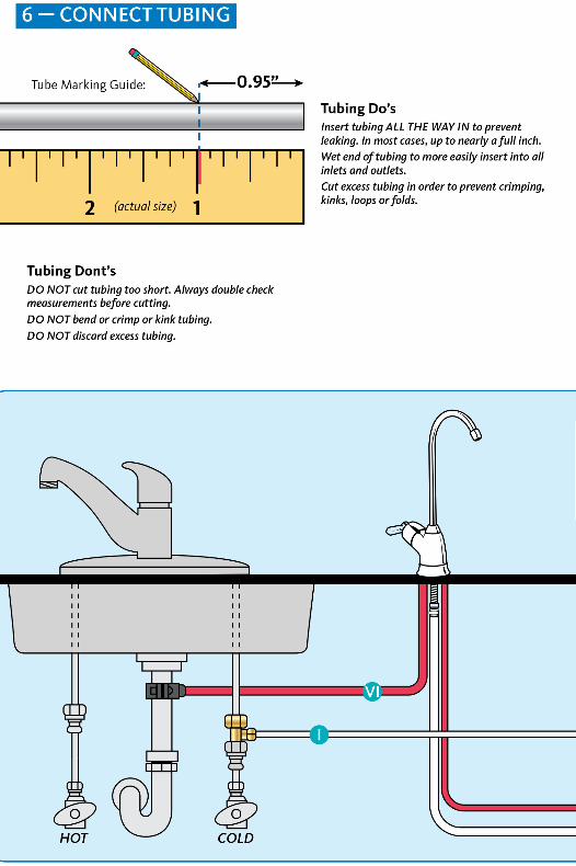
3. %” white tubing will be used to connect manifold to tank, and from faucet stem to
remineralizer. Measure out %” white tubing from the top of the tank to the outlet side of the
system manifold and mark Vs" tubing. Then measure remaining length of Ve" tubing from theremineralizer to the desired location of the faucet hole to ensure there will be enough Vs”
tubing available for both connections. Wait to cut tubing and follow instructions below.
4. Remove system, remineralizer, and tank from under your sink to begin installation.
INSTALLATION OVERVIEWStep 1 - Install Brass Tee Fitting
2 Turn on the kitchen faucet to release pressure and allow water to drain from the line.
3 Disconnect the cold water line from the 'A" threaded stem on the bottom of the kitchenfaucet. Attach threaded ends of supplied brass tee to the cold water supply line and shut-off
valve; tighten using an adjustable wrench.
4 Attach %” white tube to the brass tee:
\
y y y y y y
A. Slide the compression nut onto the white tubing.
B. Slide the plastic sleeve onto the white tube.
C. Place brass insert into the opening of white tube.
D. Push the tip of the white tubing into the opening of the brass tee.
E. Slide the compression nut onto the threads of the brass tee.
F. While holding the white tube in place, tighten the compression nut to compress the plasticsleeve and create a seal. NOTE:Use a wrench to ensure complete seal. Avoid overtightening.
5 Do not connect the other end at this time.
3- INSTALL WATER STORAGE TANK
On the nipple on top of the tank, apply Teflon®tape 4 or 5 times clockwise around in the same
direction as the threads.
Hand tighten the tank connector onto the tank
nipple until secure. NOTE: Do not cross thread or
over tighten.
Using mount stand, place tank near the system
manifold. Measure 3/8” white tubing to the outletside of the system manifold and ensure you
have enough tubing to connect tank and system
manifold as well as enough left to attach faucet
stem and remineralizer. Cut 3/8” white tubing.
1
2to"
3
(§)
2- INSTALL SYSTEM MANIFOLD
i Select an easily accessible area under the sink to mount system
manifold and remineralizer holder. You want to allow at least a 4
to 6 inch clearance below the filters to the floor to allow ample
space for filter changes. To help gauge the right location for your
system manifold, insert first and third stage filter sumps into
manifold. Insert sumps by aligning top connection points and
push up and to the right until sumps are locked in.
V
2 Mark wall placement for mounting screws using
built-in bracket on back of manifold. Make sure holes
are as level as possible. Mark screw placement of
the remineralizer holder 1 or 2 inches from the third
stage sump to the right of the manifold.
3 Drill two pilot holes for mounting brackets using 14”
drill bit for the system manifold. NOTE: Use caution
not to drill into anything beyond the cabinet wall.
4 Insert mounting screws into the wall leaving approximately %” of each screw exposed.
5 Remove first and third filter sumps from manifold by turning each sump to the left and
pulling down before hanging manifold on wall. Mount manifold on wall and screw in. Be
careful not to over tighten.
6 Screw in remineralizer holder onto wall.
atemjja
1
4 Install the 3/8” white tubing to the tank:
A. Push the tubing through the nut, collar and sleeve into the connector.
B. Unscrew the compression nut from the tank connector to ensure that the tubing is
connected all the way through the collar and sleeve.
C. Slide the nut to the threads and tighten with a wrench. Avoid over tightening.
A
4- INSTALL RO FAUCET
You willneed a sink top hole between VA” and VA” in diameter. If drilling a new hole, ensure
faucet body willmount fat against surface and that there is sufficient tubing betweenfaucetbody andsystem manifold. NOTE: Drilling holes into solidsurfaces or surfaces made ofstone
should only be performedby a qualified andcertified installer.
i Attach remaining %” white tubing to stem on faucet body by wetting tubing end and
inserting into faucet stem fitting approximately 5/8” until it stops. Gently tug on the tubingto ensure it is firmly seated in fitting.NOTE: Do not connect 3/8” white tubing from tank to faucet.
2 Mount faucet base by pushing toggle bolts through the sink hole until faucet base is flush
with countertop. Position toggle bolts under sink surface being certain faucet stem willnot be obstructed. Loosely fasten faucet base to countertop by tightening toggle bolts,alternating between left and right sides to evenly tighten. Leave loose to adjust faucet
body as desired.
3 Route the 3 tubes attached to faucet body through the faucet base and through hole in sinkuntil approximately 12” of tubing remains above sink.
4 Turn % clockwise and holding faucet base firmly, mount faucet body to faucet base. Adjustfaucet body handle to desired location.
5 To tighten faucet, hold base firmly to keep it from moving while turning faucet body % turn
counterclockwise. Tighten toggle bolts evenly, making sure not to over tighten.
6 Mount faucet body to faucet base; turn !4 turn clockwise until it locks.
7 Attach faucet spout to faucet body by screwing spout nut to body.
I
a
5
Iz3
5- INSTALL RO DRAIN CONNECTOR
WARNING CAUTION
Be sure that all electrical appliances andoutlets are turned off at the circuit breakerbefore working in the cabinet area.
Please wear safetyglasses to protect
eyes when drilling..w.
i Identify drain outlet location.
2 Remove protective cover from back of foam seal.
3 Knock center hole out, align holes, and attach to front plate of drain connector.
4 Allowing room for drilling, position the drain connector on sink drain pipe above drain trap.
5 Securely tighten nuts and screws.
6 Using drain connector port as drill guide, drill 7/32” hole through wall of drain pipe. Be sure
not to penetrate opposite side of pipe, and be careful not to damage side of drain port
Brass Tee to Manifold “INLET” (%” white tubing)iTake the white tubing leading from the brass tee and insert it into the manifold port
labeled “INLET”. Remember to push it all the way in until it stops.
II:Manifold to Remineralizer (3/s” red tubing included in packaging)11nsert one end into the manifold port labeled “FAUCET”.
2 Insert the other end into the remineralizer port labeled “INLET”.
Ill: Remineralizer to Faucet (%” white tubing already attached to faucet)iInsert the %" white tubing (that was installed in step 4) from the faucet into the
remineralizer port labeled “OUTLET”.
IV: Manifold to Tank (3/a” white tubing already attached to tank)
1Take the white tubing leading from the storage tank and insert it into the manifold port
labeled “TANK”. Remember to push it all the way in until it stops.
V: Air Gap to RO Membrane (%” red tubing from faucet)
11nsert restrictor into the end of the red tubing.2 Attach %” red tubing to the 90° elbow until it stops.
3 Attach %” 90° elbow to the membrane drain port.
V Faucet to Drain Connector (%” red tubing from faucet)
1 Take the 3/s” red tubing from faucet and insert it all the way into the drain connector.
Hose Connections:
Q Vt" White Brass Tee to Manifold
%” Red Manifold to Remineralizer Red
(J) %” White Remineralizer to Faucet Red
%” White Manifold to Tank
Membrane to Faucet
Faucet to Drain Connector
&
1(A
J'K-JT|Stage 3 i
Xtut
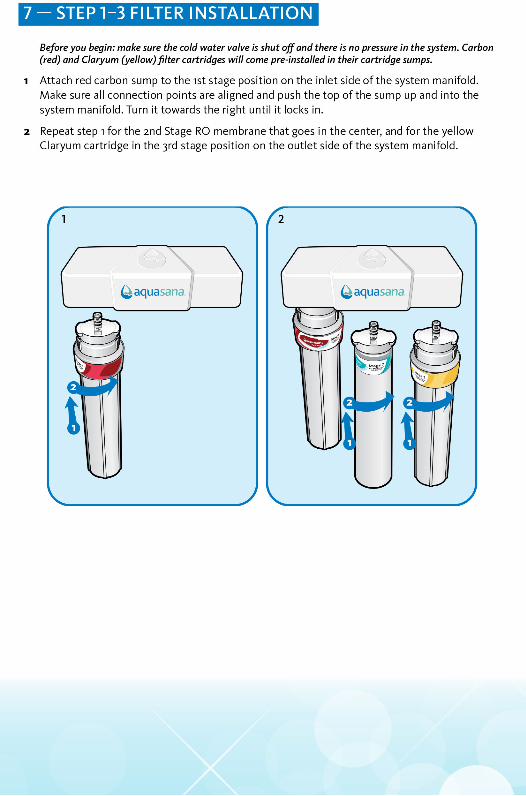
7- STEP1-3 FILTER INSTALLATION
Before you begin:make sure the coid water valve is shut off and there is no pressure in the system. Carbon(red) and Ciaryum (yellow)fitter cartridges will come pre-instaiiedin their cartridge sumps.
i Attach red carbon sump to the ist stage position on the inlet side of the system manifold.
Make sure all connection points are aligned and push the top of the sump up and into the
system manifold. Turn it towards the right until it locks in.
2 Repeat step l for the 2nd Stage RO membrane that goes in the center, and for the yellowCiaryum cartridge in the 3rd stage position on the outlet side of the system manifold.
(ÿaquasana|
rsssii
t
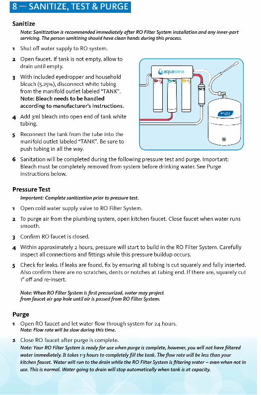
8- SANITIZE, TEST & PURGE
Sanitize
Note: Sanitization is recommended immediately after RO Fitter System installation and any inner-partservicing. The person sanitizing shouldhave dean hands during this process.
i Shut off water supply to RO system.
2 Open faucet. If tank is not empty, allow to
drain until empty.
3 With included eyedropper and householdbleach (5.25%), disconnect white tubingfrom the manifold outlet labeled “TANK”.
Note: Bleach needs to be handled
according to manufacturer’s instructions.
4 Add 3ml bleach into open end of tank whitetubing.
5 Reconnect the tank from the tube into themanifold outlet labeled “TANK”. Be sure to
push tubing in all the way.
6 Sanitation will be completed during the following pressure test and purge. Important:Bleach must be completely removed from system before drinking water. See Purge
important: Complete sanitizationprior to pressure test.
i Open cold water supply valve to RO Filter System.
2 To purge air from the plumbing system, open kitchen faucet. Close faucet when water runs
smooth.
3 Confirm RO faucet is closed.
4 Within approximately 2 hours, pressure will start to build in the RO Filter System. Carefullyinspect all connections and fittings while this pressure buildup occurs.
5 Check for leaks. If leaks are found, fix by ensuring all tubing is cut squarely and fully inserted.Also confirm there are no scratches, dents or notches at tubing end. If there are, squarely cut
1” off and re-insert.
Note: When RO Fitter System isfirst pressurized, water may project
fromfaucet air gap hole untilair is passedfrom RO Fitter System.
Purge
i Open RO faucet and let water flow through system for 24 hours.Note: Flow rate will be slow during this time.
2 Close RO faucet after purge is complete.Note: Your RO Filter System is readyfor use whenpurge is complete, however,you will not havefilteredwater immediately. It takes 7-3 hours to completelyfill the tank. Theflow rate will be less thanyour
kitchenfaucet. Water will run to the drain while the RO Filter System is filtering water - even when not in
use. This is normal. Water going to drain willstop automatically when tank is at capacity.
3-STAGE RO SYSTEM - MODEL AQ-RO-3MetricU.S.
Membrane Production1 35 gpd 132 Ipd
Membrane TDS Reduction1 95% minimum 95% minimum
System Production2 13-32 gpd 50.4 Ipd
TDS Reduction2 96.3%+ average 96.3%+ average
Maximum TDS 1000 ppm 1000 ppm
Maximum water hardness @ 6.gpH 2.64 gpLlogpg
Maximum Chlorine in water 3.0 ppm 3.0 ppm
Supply water pH limits 4-10 4-10
Drain (reject water) Flow 3-5 x product flow 3-5 x product flow
Empty Storage Tank Precharge 35-48 kPa air5-7 psi air
Storage Tank Capacity2 3.2 gallons i2.ii liters
Supply water pressure limits 275-689 kPa40-100 psi
Supply water temperature limit 40-100° F 5-37° C
Efficiency3 17.91% 17.91%
Recovery4 29.43% 29.43%
Specifications - Qualified System Performance
Because the performance of a Reverse Osmosis Membrane is highly dependent upon pressure,
temperature and TDS, the following should be used for comparison purposes only.
1 Industry standards measure RO Membranes performance with no back pressure on the
product water, at 60 psig (4i4l<Pa) and 77°F (25°C). Further conditions on the above are 250ppm TDS and a 30.6% recovery rate. Production rate and TDS reduction figures are for a new
Membrane that has been rinsed for 24 hours. The production rate of a new Membrane can
decrease by 10% per year or more, depending upon the scaling and fouling tendencies of theFeed Water.
2 Measured at 50 psi, 77°+2°F, and 717 mg/I TDS per NSF/ANSI Standard 58.
3 Efficiency rating means the percentage of the influent water to the system that is availableto the user as reverse osmosis treated water. Under operating conditions that approximate
typical daily usage.
4 Recovery rating means the percentage of the influent water to the membrane portion of
the system that is available to the user as reverse osmosis treated water when the system is
operated without a storage tank or when the storage tank is bypassed.
/j\ Do not use with water that is microbiologically unsafe or of unknown water qualitywithout adequate disinfection before or after the system. Systems certified for cyst
reduction may be used on disinfected waters that may contain filterable cysts.
/5\ Filter is only to be used with cold water. Systems certified for cyst reduction may be
used on disinfected water that may contain filterable cysts.
Non-potable Water Sources:Do not attempt to use this product to make safe drinking water from non-potable water
sources. Do not use the system on microbiologically unsafe water, or water of unknown qualitywithout adequate disinfection before or after the system. This system is certified for cyst
reduction and may be used on disinfected water that may contain filterable cysts.
Arsenic Reduction:Arsenic (abbreviated As) is found naturally in some well water. Arsenic in water has no color,taste, or odor. It must be measured by a laboratory test. Public water utilities must have their
water tested for arsenic. You can get the results from your water utility. If you have your own
well, you can have the water tested. The local health department or the state environmentalhealth agency can provide a list of certified labs. The cost is typically $15 to $30. Information
about arsenic in water can be found on the Internet at the U.S. Environmental Protection
There are two forms of arsenic: pentavalent arsenic (also called As(V), As(+5), and arsenate)
and trivalent arsenic (also called As(lll), As(+3), and arsenite). In well water, arsenic may bepentavalent, trivalent, or a combination of both. Special sampling procedures are needed for a
lab to determine what type and how much of each type of arsenic is in the water. Check with
the labs in your area to see if they can provide this type of service.
Reverse osmosis (RO) water treatment systems do not remove trivalent arsenic from water verywell. RO systems are very effective at removing pentavalent arsenic. A free chlorine residual willrapidly convert trivalent arsenic to pentavalent arsenic. Other water treatment chemicals suchas ozone and potassium permanganate will also change trivalent arsenic to pentavalent arsenic.
A combined chlorine residual (also called chloramine) may not convert all the trivalent arsenic.
If you get your water from a public water utility, contact the utility to find out if free chlorine or
combined chlorine is used in the water system.
The AQ-RO-3 system is designed to remove pentavalent arsenic. It will not convert trivalent
arsenic to pentavalent arsenic. The system was tested in a lab. Under testing conditions, the
system reduced [0.3 mg/L (ppm) or 0.050 mg/L (ppm)] pentavalent arsenic to 0.010 mg/L
(ppm) (the USEPA standard for drinking water) or less. The performance of the system may bedifferent at your installation. Have the treated water tested for arsenic to check whether thesystem is working properly.
The RO component of the AQ-RO-3 system must be replaced every 1-3 years to ensure that
the system will continue to remove pentavalent arsenic. The component identification andlocations where you can purchase the component are listed in the installation/operation manual.
Nitrate/Nitrite Test Kit:This system is acceptable for treatment of influent concentration of no more than 27mg/l_nitrate and 3mg/L nitrite in combination measured as N.* This system is supplied with a nitrate/
nitrite test kit. Product water should be monitored periodically according to the instructions
provided with the test kit.
*Nitrate/Nitrite reduction is not part ofNSF Certification.
Installations in The Commonwealth of Massachusetts:The Commonwealth of Massachusetts requires installation be performed by a licensed plumberand do not permit the use of saddle valves. Plumbing code 248—CMR of the Commonwealth ofMassachusetts must be followed in these cases.