Page 1
8/14/2019 Livewind Report
http://slidepdf.com/reader/full/livewind-report 1/92
i
Acknowledgement
First of all, I would like to thank KIST College of Management and
Tribhuvan University (T.U) for providing such course which helped
me in gaining a lot of knowledge in Information Management and
also I feel myself grateful for having a chance to work in the
industrial attachment project as an intern in the organization.
Secret behind every successful project is proper planning, sufficient
preliminary studies and smart implementation of planned activities.
Continuous help from various persons was vital in achieving the
goals to come up with solid project outcomes. In this regard, the
authors would like to express their vote of thanks to following
people/organizational unit.
• Faculty of Management.
• Project Supervisors Dilli Prasad Sharma for the support and
encouragement in proceeding with the project.
• Program Co-coordinator, Bijendra Nath Shukla
• Aman Ratna Tuladhar, project supervisor for his helpful
suggestion and supervision.
• Code Arts Nepal Pvt. Lt. for its guidelines and support for the
project.
• My friends and family for their direct or indirect support in
project study.
Thank You
Prajwal Tuladhar
September, 2008
Page 2
8/14/2019 Livewind Report
http://slidepdf.com/reader/full/livewind-report 2/92
ii
Abstract The project report on "Livewind - Project Management System" has
been prepared for the fulfillment of the requirement for the degree
of BIM. The report contains the full documentation about the
project.
Livewind is a project management system. It is built as a
replacement of the existing system. The existing system lacks
integration among several project components and communication
flow among project members. Livewind is a web based system so it
can be easily accessed within the organization's intranet.
By using Livewind, the organization can manage any IT project
effectively and efficiently within the scope, quality, time and
budget. It will optimize the allocation and integration of inputs
necessary to meet pre-defined objectives. Project members can
view the current activities of the project so that they can remain
updated and moreover it will solve the communication and
integration problem in managing the project.
The system has been developed and designed from the scratch
using Microsoft .NET platform 3.5.
Page 3
8/14/2019 Livewind Report
http://slidepdf.com/reader/full/livewind-report 3/92
iii
Acronyms
• CRUD : Create Read Update Delete
• CSS : Cascading Style Sheet
• DOM : Document Object Model
• DLL : Dynamic Link Library
• DFD : Data Flow Diagram
• FURPS : Functional Usability Reliability Performance and
Supportability
• GUI : Graphical User Interface
• LINQ : Language Integrated Query
• NIC : Network Interface Card
• O/R Mapping or ORM : Object Relational Mapping
• RAM : Random Access Memory
• RSS : Really Simple Syndicate
• UP : Unified Process
• W3C : World Wide Web Consortium
Page 4
8/14/2019 Livewind Report
http://slidepdf.com/reader/full/livewind-report 4/92
iv
List of figures
FIGURE 4.1 –1 ANALYSIS OF THE EXISTING SYSTEM ................................................. .............12
FIGURE 4.2 –1 GENERAL DESCRIPTION OF THE SYSTEM ......................................................... .13
FIGURE 4.3 –1 CONTEXT LEVEL DFD...................................................................... ......15
FIGURE 4.5 –1 USE CASE DIAGRAM FOR THE APPLICATION ......................................................20
FIGURE 4.6 –1 OVERALL SYSTEM DESIGN ................................................................. ........28
FIGURE 4.6 –2 FLOW CHART OF THE ENTIRE SYSTEM .......................................... ..................31
FIGURE 4.6 –3 SEQUENCE DIAGRAM FOR SITE KEY REGISTRATION ...............................................33
FIGURE 4.6 –4 SEQUENCE DIAGRAM FOR CREATE PROJECT ......................................................33
FIGURE 4.6 –5 SEQUENCE DIAGRAM FOR ACCESS CONTROL .....................................................34
FIGURE 4.6 –6 SEQUENCE DIAGRAM FOR CREATE MILESTONE ...................................................34
FIGURE
4.6 –7 SEQUENCE
DIAGRAM
FOR
CREATE
MESSAGE
.....................................................35FIGURE 4.6 –8 SEQUENCE DIAGRAM FOR COMMENT MESSAGE ..................................................35
FIGURE 4.6 –9 SEQUENCE DIAGRAM FOR TO-DO LIST ......................................................... ...36
FIGURE 4.6 –10 SEQUENCE DIAGRAM FOR CREATE TO-DO ITEM ................................................36
FIGURE 4.6 –11 OVERALL CLASS DIAGRAM FOR THE SYSTEM WITH CLASS NAME ONLY .......................39
FIGURE 4.6 –12 DATACONTEXT CLASS FIELDS AND PROPERTIES ........................................ .......41
FIGURE 4.6 –13 DATACONTEXT CLASS METHODS ........................................................ ......43
FIGURE 4.6 –14 O THER MAPPED ENTITIES CLASS .......................................................... ......55
FIGURE 4.6 –15 ER DIAGRAM FOR THE NEW SYSTEM ................................................. ..........57
FIGURE 4.6 –16 ENTITY METADATA INFORMATION (DATA DICTIONARY).........................................61
FIGURE 5.1 –1 DEPLOYMENT VIEW OF THE NEW SYSTEM ........................................................64
FIGURE 5.2 –1 HIGHER LEVEL SYSTEM ARCHITECTURE ...........................................................65
FIGURE 5.2 –2 HIGHER LEVEL SYSTEM ARCHITECTURE OVERVIEW ...............................................68FIGURE 5.4 –1 LIVEWIND LOGIN PAGE ............................................................................69
FIGURE 5.4 –2 LOGGED IN PAGE .............................................................. ....................70
FIGURE 5.4 –3 CREATE PROJECT PAGE ........................................................ ....................71
FIGURE 5.4 –4 PROJECT DETAIL PAGE ............................................................ .................72
FIGURE 5.4 –5 MILESTONE PAGE ................................................................... ...............73
FIGURE 5.4 –6 PROJECT MESSAGE PAGE .................................................... ......................74
FIGURE 5.4 –7 TO-DO LIST PAGE ................................................................................. .75
Page 5
8/14/2019 Livewind Report
http://slidepdf.com/reader/full/livewind-report 5/92
v
1 Table of contents
ACKNOWLEDGEMENT...........................................................................I
ABSTRACT..........................................................................................II
ACRONYMS........................................................................................III
LIST OF FIGURES...............................................................................IV
TABLE OF CONTENTS .............................................................................. .....................V
1 INTRODUCTION.............................................................................1
1.1 BACKGROUND ........................................................................................... ........1
1.2 OBJECTIVES OF THE STUDY ..................................................................................... 2
1.3 METHODOLOGY OF THE STUDY ................................................................................ .2
1.3.1 Organization selection.......................................................................21.3.2 Placement / Duration / Activities........................................................2
1.3.3 Work procedure................................................. ................................3
1.3.4 List of tasks........................................................................... .............4
1.4 TOOLS USED ................................................................................... .................4
2 INTRODUCTION OF THE INDUSTRY .................................................6
2.1 INTRODUCTION .................................................................................. ................6
2.1.1 Features of the IT industry .................................................................7
2.2 SOFTWARE INDUSTRY .............................................................................. .............7
3 INTRODUCTION OF THE ORGANIZATION.........................................9
3.1 INTRODUCTION TO CODE ARTS NEPAL .................................................. .....................9
3.2 MISSION AND VISION OF CODE ARTS NEPAL ..............................................................10
3.3 ORGANIZATION’S SERVICES ........................................................ ..........................10
4 PROBLEM AND ANALYSIS.............................................................12
4.1 ANALYSIS OF EXISTING S YSTEM ................................................................ .............12
4.2 DESCRIPTION OF THE SYSTEM UNDER STUDY ...................................... .........................12
4.3 INITIAL INVESTIGATION .......................................................................... ..............14
4.3.1 Preparing and summary of the interview.........................................14
4.3.2 Flow of Information................................................ ..........................14
4.3.2.1 DFD............................................................................ .........................14
4.3.3 Deliveries and reports........................................................ ..............16
4.3.4 Users’ skill level.................................................. .............................16
4.4 PROBLEM WITH THE EXISTING SYSTEM ........................................... ...........................16
4.5 REQUIREMENT ANALYSIS ................................................................. ....................17
4.5.1 User’s need assessment (Functional requirements).........................17
4.5.2 Non-functional requirements (Technical requirements)....................17
Page 6
8/14/2019 Livewind Report
http://slidepdf.com/reader/full/livewind-report 6/92
vi
4.5.3 Use-case modeling............................................................... ............18
4.5.4 Use case diagram.......................................................................... ...19
4.5.4.1 Use cases.................................................................. ..........................20
4.6 OVERALL SYSTEM DESIGN ..................................................................... ...............28
4.6.1 Input of the new system............................................................... ....284.6.2 Process of the new system....................................................... ........29
4.6.3 Output of the new system..................................................... ...........29
4.6.4 Salient features of the new system..................................................30
4.6.5 Flow of the new system................................................................. ...31
4.6.5.1 Entire application........................................................................... ......31
4.6.6 Sequence Diagram................................................................... ........32
4.6.6.1 Sequence diagram in the context of the new system........................... 32
4.6.7 Logical architecture of the new system...................................... ......37
4.6.7.1 UML Class diagram......................................................... .....................37
4.6.8 Database design.................................................... ..........................56
4.6.8.1 Entity relationship diagram........................................................... .......56
4.6.8.2 Entity metadata information (Data dictionary)................................. ....58
4.6.8.3 Entity description............................................................................. ....61
5 SYSTEM IMPLEMENTATION..........................................................63
5.1 DEPLOYMENT DIAGRAM AND VIEW ......................................................... ..................63
5.2 ARCHITECTURE OF THE NEW SYSTEM ............................................................... .........65
5.2.1 Application platform overview..................................................... .....65
5.2.2 Higher level system architecture overview......................................68
5.3 IMPLEMENTATION STRATEGY ................................................... ...............................69
5.4 APPLICATION SNAPSHOTS AND DESCRIPTION .......................................... ......................69
5.4.1 Login page............................................................. ..........................69
5.4.2 Logged in page................................................... .............................70
5.4.3 Create project page........................................... ..............................71
5.4.4 Project detail page..................................................... ......................72
5.4.5 Milestone page........................................................................ .........73
5.4.6 Message page............................................................... ...................74
5.4.7 To-do list page.......................................................................... ........75
6 CONCLUSION..............................................................................76
6.1 LESSONS LEARNT ........................................................................ .....................76
APPENDICES.......................................................................................A6.2 QUESTIONNAIRES ................................................................................ ...............A
Page 7
8/14/2019 Livewind Report
http://slidepdf.com/reader/full/livewind-report 7/92
vii
1
2
3 Introduction
2 BackgroundBachelor in Information Management (BIM) is the four year IT
course offered by Tribhuvan University. It is an integrated course
which has blended management education with recent
developments in IT. The mission of Faculty of Management's
Bachelor in Information Management (BIM) program is to develop
socially responsible, scientific approached, result oriented
information technology (IT) professionals. The BIM program isdesigned to equip graduates with the skills and attributes required
to be effective and efficient information technology professionals.
As per the requirement for BIM degree, this internship has been
performed. Students can apply all knowledge that has been learnt
in the class room to the practical field. We can define this as a
practical of all subject and techniques learned in the class.
As a student of BIM, IT and management courses are studied in theduration of four years program. It dragged my interest in
programming (web development) and Software Company as always
the best choice for me. Among an assortment of all the software
company, Code Arts Nepal was chosen as it is a company with full
Page 8
8/14/2019 Livewind Report
http://slidepdf.com/reader/full/livewind-report 8/92
viii
support of technology and other infrastructure. The company was
also capable of providing greater future prospect. The organization
is located at Gyaneshwore, Kathmandu.
3 Objectives of the study
The primary objective of this internship is to study about the flow of
project management system in an IT organization and understand
how the process can be made simple yet effective. The other
specific objectives are as follows:
To create a project management system that could integrate all the
project components as well as its users.
• To understand the current trend in the web development
along with technology used
• To find out appropriate solution of the problem domain
• For partial fulfillment of internship project as per the final
year requirement assigned by the University
4 Methodology of the study
4.1 Organization selection
According to the course of BIM degree of TU, students are required
to do the intern on their interest which is related to what they have
studied in their four year course. As the area of the interest of the
internee is software development, relevant Software Company has
been chosen to perform internship work. Among the assortment of
Software Company, the internee choose Code Arts Nepal since it is
one of the promising and flourishing company with full support of
technical professional and provides us a greater future prospect for
Page 9
8/14/2019 Livewind Report
http://slidepdf.com/reader/full/livewind-report 9/92
ix
both learning and opportunity. The organization is located in
Kathmandu City at Gyaneshwore.
4.2 Placement / Duration / Activities
The official duration of our internship as per the requirement of
Tribhuvan University (TU) is eight weeks. Hands-on experience was
given on many aspects from web page designing, to standard
maintaining code, agile development and other significant tasks
that could prove fruitful in the practical world. The internship period
started from June 01 and lasted till August 25, 2008 meeting the
requirement.
The primary task assigned was to make web-based system for
managing IT projects or a project management system. Work was
carried out under the supervision of the technical officer of the
organization and under the program associate who looked after
other organizational activities.
Working with the professionals who did not have enough time to
cover up all their work but they were cooperative enough to tell
what they want from the new system and with essential guide on
how to make that happen.
4.3 Work procedure
Completing an application with self-design and self-coding is not an
easy task in just 2 months. The work was initiated with the study of
the organizational background. Functional requirements were taken
from Ms. Deepa Rai who is looking after Code Arts Nepal’s project
overflow activities. Then with those functional requirements, viable
non-functional or technical requirements were discussed with Mr.
Aman Tuladhar for the fulfillment of the requirement. The project
has been code named ‘Livewind ’.
Page 10
8/14/2019 Livewind Report
http://slidepdf.com/reader/full/livewind-report 10/92
x
Some major activities:
• Step by step collection of the requirements
• Step by step requirement collection
• Development and enhancement
• System design and analysis
• Coding from scratch
• Testing and debugging
• Project documentation
• Implementation of the new system
4.4 List of tasks• Requirement analysis
• Requirement specification
• System and interface design
• Coding
• Implementation and testing
• Documentation
5 Tools used
A dynamic website can be developed in many ways with options to
use many databases, web programming languages and other
Page 11
8/14/2019 Livewind Report
http://slidepdf.com/reader/full/livewind-report 11/92
xi
supporting applications and integrated development environments
(IDE). Microsoft .NET framework has been used as a platform for
application development and MS SQL Server Express Edition has
been used to perform database related tasks. List of tools used are
listed below:
• Microsoft .NET framework 3.5: Used as an web application
platform
• Microsoft SQL Server 2005 Express Edition: Used as a
database server
• Internet Information Services (IIS) 6.x: Used as a web server
• Visual Studio 2008 Express Edition: IDE for application
development
• Adobe Photoshop: For graphics related tasks
• Microsoft Visio 2007: For constructing UML and software
models diagrams
• Rational Rose: For constructing UML and software models
diagrams
• SQL Server Management Studio Express Edition: An easy-to-
use graphical management tool for managing SQL Server
2005 Express Edition
Page 12
8/14/2019 Livewind Report
http://slidepdf.com/reader/full/livewind-report 12/92
xii
1 Introduction of the industry
1.1 Introduction
6 Introduction
An industry is generally any grouping of business that share a
common method of generating profits, such as the music industry,
the automobile industry or the cattle industry. It is also used
specifically which involves large amount of capital investment
before any profit can be realized, also called heavy industry.
IT is one of the most dominant and growing industry in the global
economy today. The dynamic technological advancement in the
information technology has reinforced the changes in the economy
and social sector that are transforming the business and society. In
view of this new kind of economy-information economy, the
software development activity is expected to grow importance of
software services. No need to displace and rehabilitate the tribes
and no need to earn money by selling precious metals. Software
industry can solve these issues up to some extent to boom our
economy. The over drafted state can be paid monthly regularly
salaries to employees and spend more money in health, education
and other development activities.
The IT industry has become of the most robust industries in theworld. IT, more than any other industry or economic facet, has an
increased productivity, particularly in the developed world, and
therefore is a key driver of global economic growth. Economies of
Page 13
8/14/2019 Livewind Report
http://slidepdf.com/reader/full/livewind-report 13/92
xiii
scale and insatiable demand from both consumers and enterprises
characterize this rapidly growing sector. The Information
Technology Association of America (ITAA) explains the “information
technology” as encompassing all possible aspects of information
systems based on computers. Both software development and the
hardware involved in the IT industry include everything from
computer systems, to the design, implementation, study and
development of IT and management systems. Owing to its easy
accessibility and the wide range of IT products available, the
demand for IT services has increased substantially over the years.
The IT sector has emerged as a major global source of both growthand employment.1
6.1 Features of the IT industry
• Economies of scale for the information technology industry
are high. The marginal cost of each unit of additional software
or hardware is insignificant compared to the value addition
that results from it.
• Unlike other common industries, the IT industry is knowledge-
based.
• Efficient utilization of skilled labor forces in the IT sector can
help an economy achieve a rapid pace of economic growth.
• The IT industry helps many other sectors in the growth
process of the economy including the services and
manufacturing sectors.
1http://www.economywatch.com/business-and-economy/information-technology-industry.html
Page 14
8/14/2019 Livewind Report
http://slidepdf.com/reader/full/livewind-report 14/92
xiv
7 Software industry
The Software Industry, which is a main component of the
Information technology, has brought tremendous success for the
emerging economy.
The software industry comprises businesses involved in the
development, maintenance and publication of computer software.
The software industry started in the mid-1970s at the time of the
personal computer revolution. The industry also includes software
services, such as training and consultancy. The largest and most
profitable of software companies are located in the United States.
As of 2006, the client software industry is dominated by Microsoft
but the trend is shifting to the web at considerable rate. Software
Magazine's 500 list in 2005 shows the total amount of revenue
brought in by software companies per locale, with the highest being
California due to Silicon Valley and the amount of Fortune 500
software companies residing in that area. There are mainly two
types of businesses in the software industry; those developing
proprietary software such as Microsoft, and those developing opensource software. Developing proprietary software is costly and
involves software licensing and the need to protect the software
from cracking and piracy. The main financial return on open source
comes from selling services, such as training and support, rather
than the software itself. Many contributors to open source software
(especially those developing software tools) also feel that there is a
significant long-term return in the form of improved resources and
capabilities within the software industry. Despite doing much
business in proprietary software, some companies like Sun
Microsystems and IBM participate in developing free and open
Page 15
8/14/2019 Livewind Report
http://slidepdf.com/reader/full/livewind-report 15/92
xv
source software to deter from monopolies and take a portion of
their market share.2
2http://en.wikipedia.org/wiki/Software_Industry
Page 16
8/14/2019 Livewind Report
http://slidepdf.com/reader/full/livewind-report 16/92
xvi
2 Introduction of the
organization
2.1 Introduction to Code Arts Nepal
8 Introduction to Code Arts Nepal
Code Arts Nepal Pvt. Ltd. is a professional software development
company which was founded in the year 2004 A.D. by group of
individualists with the mission to provide and promote quality
technical services and product in the field of IT.
Code Arts Nepal is a full-service web solution provider. They
specialize in creating Strategic E-Business Solutions that allow
companies to leverage the web to streamline business
communications, collaborate with internal team members and
external partners, and conduct commerce online.
Since 2004, they have been working with organizations ranging
from public listed companies to midsize businesses and small
entrepreneurial enterprises. The company was established in
response to the growing market demand for quality web solutions.
The clients of Code Arts Nepal are mainly the overseas customers.
Considering time and satisfaction as primary focus, Code Arts Nepal
makes extensive investment both in terms of time and money to
ensure this objective.
Code Arts Nepal expertise in website development ranges to easy
to use simple web dynamics to robust and interactive web
Page 17
8/14/2019 Livewind Report
http://slidepdf.com/reader/full/livewind-report 17/92
xvii
applications with integrated web applications with integrated
database to provide seamless, secure management of your
organization’s data. This includes website for personal, institutions,
e-commerce to name just few.
Apart from web based applications, Code Arts Nepal also developed
customized software product to carter any organization’s specific
need. Code Arts Nepal provide distributed, scalable application
software solution to ensure that your business is managed
efficiently and supported with latest technology available in
market.
9 Mission and vision of Code Arts Nepal
Code Arts Nepal’s mission is to provide cutting edge technology to
organization for which easy access to information is important.
Code Arts Nepal prepares Management Information System for
clients to strengthen its Information Management through the use
of modern computing system. They do not believe in being
technically clever just for the sake of it. Rationality of purpose for aclient's site is always uppermost in their minds. To summarize, their
basic company philosophy is to create the kind of website that
most businesses want; easy to find, stylish and appealing, quick
loading, easy to navigate and easy to buy from.
10Organization’s services
The services provide by Code Arts Nepal includes the following:
• Web Development: Code Arts Nepal is the premier developer
of custom web software. Code Arts Nepal develops software
that carters your standard and work process. From website-
design to web-development through to the complex
Page 18
8/14/2019 Livewind Report
http://slidepdf.com/reader/full/livewind-report 18/92
xviii
programming with back-end integrated database support,
code Arts Nepal has the team to match core business
requirements. The field of web development includes:
○ Web design
○ Web application development
○ Web hosting
○ Domain registration
○ Database driven personal and enterprise web
application
○ Web portals
○ Online chat service
• E-Commerce: Code Arts Nepal provides e-commerce service
building a website further enhances business by enabling
online transactions.
• Application Development: The ability to develop robust,
feature-rich and quality enterprise is a must in today’s
competitive business environment. Code Arts Nepal utilizes
its experience in the field of application development,
integration, maintenance as well as knowledge of
multiplatform environments to the full to create optimally
integrated business applications that both support and
enhance tour business.
• Distributed Solutions: Code Arts Nepal has advances
significantly to bring forth the concept of Distributed
Systems, in other words systems, distributed globally, whichshare work between themselves to provide a specialized
accurate and timely solution to these ever increasing needs.
The system in question could be computer systems which
Page 19
8/14/2019 Livewind Report
http://slidepdf.com/reader/full/livewind-report 19/92
xix
may be located in any office which in turn may be located
anywhere in the world. This concept of distributed system
can be brought to software completely automated
management of organization’s global needs. In other words,
we can build distributed, enterprise software to cater to all
the above mention needs. Various software technologies and
framework are available for developing distributed system
out of which J2EE is extremely popular.
• Intranet Solutions: Code Arts Nepal develops innovative
intranet based product and services to help client save time
and enhance their bottom line when it comes to managing
their business efficiently.
3 Problem and Analysis
3.1 Analysis of Existing System
11Analysis of Existing System
Currently, Code Arts does not have any concrete project
management system. Projects are being managed in an informal
way. Online conferencing, word processors and emails are used as
primary tools to organize project activities. This has created
obstacles in dealing with scope, quality, time and budget of the
projects. There is a definite lack of tool for collaborating activities
among project members.
Page 20
8/14/2019 Livewind Report
http://slidepdf.com/reader/full/livewind-report 20/92
xx
Figure –1 Analysis of the existing system
12Description of the system under study
Since there is no concrete project management system, the
existing system in the organization is manual rather than database
driven and unsystematic. The major problem in the existing system
is the lack of integration of project components and collaboration
platform for project members. The existing system can perform
well when the project is smaller and there is few or no involvement
of other members. Especially in the case of IT projects, the
requirements of the users tend to be changing with the flow of time
and also incrementing resulting in the complexity.
Thereby, the primary requirement of the organization is to have the
system that can assist the stakeholders of the system to stay
organized , connected and prepared . The system should have
customized user account in order to login and browse project
Page 21
8/14/2019 Livewind Report
http://slidepdf.com/reader/full/livewind-report 21/92
xxi
associated with the user. According to the access level provided to
the user, the user can create and make changes in a project,
associated milestones, and messages and to do lists.
Figure –1 General description of the system
13Initial investigation
For the initial investigation, I had allocated two weeks. The initial
investigation compromised of finding out all the facts about the
current system. I have figured out considerable number of flaws in
the existing system.
13.1Preparing and summary of the interview
For the initial investigation, both functional and non-functional
requirement related questions in advance were prepared so that
the time would not be wasted. Program Assistant was asked all the
Page 22
8/14/2019 Livewind Report
http://slidepdf.com/reader/full/livewind-report 22/92
xxii
questions to fulfill the requirement. He had given me some
requirements so that documentation could be done and get the
result as requirement specification.
The gathered requirements provided better vision of how to make
the system. It demanded to have ability to integrate several project
components with the project stake holders.
13.2Flow of Information
For showing structural flow of information of the system, data flow
diagram has been used.
13.2.1DFD
A DFD is a graphical representation of the "flow" of data through an
information system. DFD is a network representation of a system.
The system may be automated, manual, or mixed. The DFD
portrays the system in terms of its component pieces, with all
interfaces among the components indicated. It focuses on the
movement of data between external entities and processes, and
between processes and data stores. It is especially used for
structural analysis and communicating with technical and non-
technical stake holders of the system.
Page 23
8/14/2019 Livewind Report
http://slidepdf.com/reader/full/livewind-report 23/92
xxiii
Figure –1 Context level DFD
Page 24
8/14/2019 Livewind Report
http://slidepdf.com/reader/full/livewind-report 24/92
xxiv
13.3Deliveries and reports
The complete system was delivered to the organization and the
system did help to manage the project much efficiently and in a
systematic manner. Along with the system manual has also been
provided to the system user so that they could use the system
easily.
13.4Users’ skill level
It has been assumed that the users of the system will likely to be
related to the technical fields. The user must have the general idea
of how a project is handled with the concept of milestones, to do
lists and message interactions. The system is likely to be easier to
use for users.
14Problem with the existing system
The obstacles the organization was facing while managing any
project are listed below:
• The inability to integrate project components and user
interactions within the project in systematic way.
• No concrete system to manage the project flow.
• Problems in being organized connected and prepared.
• Problems in dealing with scope, quality, time and budget
constraints.
• The existing system lacks the ability to generate real time
report about any projects.
• The existing system does not have the ability to define
milestone and to evaluate which milestones are upcoming
and which are being late.
Page 25
8/14/2019 Livewind Report
http://slidepdf.com/reader/full/livewind-report 25/92
xxv
• The existing system does not have the feature to integrate
to-do lists and corresponding to-dos.
• Hierarchical message and comment interchange is not
available in the existing system
15Requirement Analysis
15.1User’s need assessment (Functional requirements)
The main users of the application from the supervision,
administration and general usage point of view are people involved
in the project like developers, analysts, designer, project manager,
non-technical stakeholders, testers and documenters. The project
manager is the main person who will create a project and manage
the overall flow of certain project. Project manager generally tends
to be from IT and/or management background with several years of
experience of managing an IT project having knowledge of
outsourcing in some magnitude. On need assessment, the project
manager for Code Arts mentioned the following requirements of the
application:
• Simple and user friendly user interface
• Easy to use with scope of expansion and high degree of
flexibility in terms of inter-operability of data format,
information exchange and so on.
• Centralized application command i.e. concept of super
administrator
• Easily manageable application and fast to load
• Support for real time report generation of a single project or
combined multiple projects
Page 26
8/14/2019 Livewind Report
http://slidepdf.com/reader/full/livewind-report 26/92
xxvi
15.2Non-functional requirements (Technical
requirements)
The non-functional requirements can be divided into software and
hardware which are described as follows.
15.2.0.1Server requirements
Software
• Windows Server 2003 or above
• ASP.NET 3.5 or above
• Internet Information Services 6 or above
• Microsoft SQL Server 2005 or above
Hardware
• Intel or AMD Multi Core Processors (Intel Xeon or AMD
Barcelona)
• 2GB RAM; 4GB Recommended
• 24/7 Network monitoring
15.2.0.2Client requirements
Software
• Operating System with GUI support
• Web browser supporting JavaScript, CSS, and W3C DOM
• A internet connection preferably cable connection and
intranet system (Mozilla Firefox 2.x, Internet Explorer 6.x,
Opera 8)
Hardware
• 256 MB RAM (Minimum); 512 MB (Recommended)
• 100 Mbps NIC (If Used in an intranet environment)
Page 27
8/14/2019 Livewind Report
http://slidepdf.com/reader/full/livewind-report 27/92
xxvii
15.3Use-case modeling
The UP defines the Use-Case Model within the requirements
discipline. Primarily, this is the set of all written use cases; it is a
model of the system’s functionality and environment. Use cases
and use case diagram has been included to visualize the functional
requirements of the system. Use case modeling are a key
requirements input to class Object Oriented Analysis and Design.3
15.4Use case diagram
A use case diagram is a type of behavioral diagram defined by the
Unified Modeling Language (UML) and created from a Use-case
analysis. Its purpose is to present a graphical overview of the
functionality provided by a system in terms of actors, their goals
(represented as use cases), and any dependencies between those
use cases. 4
The Use case diagram is used to identify the primary elements and
processes that form the system. The primary elements are termed
as "actors" and the processes are called "use cases." The use case
diagram shows which actors interact with each use case. A use
diagram is an excellent picture the system context; it makes good
context diagram that is, showing the boundary of the system, what
lies outside of it and how it gets used. It serves as a communication
tool that summarizes the behavior of a system and its actors.
The use case diagram for Livewind shows primary actors and their
interaction with various processes or use cases.
3Applying UML and Patterns – Craig Larman 3rd Edition p 65
4Wikipedia article http://en.wikipedia.org/wiki/Use_cases
Page 28
8/14/2019 Livewind Report
http://slidepdf.com/reader/full/livewind-report 28/92
xxviii
User Validate Registration
Project
Components
Project Is Valid
Message Exists
ToDo List Exists
General User
<<extends>>
Create Project
Provide Access Control
Register Site Key
<<include>>
Create Milestone
Create Message
<<include>>
Comment Message
<<include>>
<<include>>
Create ToDo List
Create ToDo Task
<<include>>
<<include>>
Administrator
<<extends>>
Project Exist
<<include>>
Use Exists
<<include>>
<<include>>
<<include>>
Figure –1 Use case diagram for the application
15.4.1Use cases
Use cases are requirements, primarily functional or behavioral
requirements that indicate what the system will do. In terms of the
FURPS+ requirements types, they emphasize the “F” (functional or
behavioral), but can also be used for other types, especially when
those other types strongly relate to a use case. In the UP and many
other methods, use cases are the central mechanisms that are
recommended for their discovery and definition.
Page 29
8/14/2019 Livewind Report
http://slidepdf.com/reader/full/livewind-report 29/92
xxix
Some of the identified use cases are listed below.
Use Case C1: Register Site Key
Scope: Livewind Application
Level: user goalPrimary Actor: AdministratorStakeholders and Interests:
1. Administrator: Wants to register site key to host
multiple projectsPreconditions: Enter the registration form for registering
site keySuccess Guarantee: Site key is registered. Authentication
email is sent to the user to activate the account.Main Success Scenario:
1. User enters the registration form for registering the
site.
2. User registers the site
3. Activation email is sent to the user
4. User activates the account by clicking the link sent
through email
5. User is now the administrator of the site which he/she
has registeredExtensions:
2a. Invalid site key:
1. System signals error and rejects registration.
2. User responds to the error
a) User enters alpha numeric characters as a site key
b) Registration form is filled by the user
2b. Email is sent to the user with unique activation key
2c. By using the activation key, the user is able to complete
the site registration
Page 30
8/14/2019 Livewind Report
http://slidepdf.com/reader/full/livewind-report 30/92
xxx
Special Requirements:
• User activation with the unique key within 3 days of
initial registration
• Pluggable business rules to be inserted for validation
purpose of registration form
Use Case C2: Create Project
Scope: Livewind ApplicationPrimary Actor: user goalStakeholders and Interests:
1. Administrator: Wants to create project for managing it
efficientlyPreconditions: User is logged in, the access level for the
user is administrator and site has already been registered.Success Guarantee: Project is created.Main Success Scenario:
1. User enters the project creation form for creating a
project
2. User completes the form and submit to create projectExtensions:
2a. Invalid Project Name
1. System signals error and rejects project creation.
2. User responds to the error
a) User enters alpha numeric character as a project name
2b. Project name already exists
1. System signals error and rejects project creation.
2. User enters project name different from previously
entered
Page 31
8/14/2019 Livewind Report
http://slidepdf.com/reader/full/livewind-report 31/92
xxxi
Use Case C3: Provide access control
Scope: Livewind ApplicationPrimary Actor: user goal
Stakeholders and Interests:1. Administrator: Wants to create access control to users
so that they could access only concerned components
2. General User: Wants to be known which project
components they could accessPreconditions: User is logged in. User must have
administrative privilege to perform access controlSuccess Guarantee: Access control to general users are
definedMain Success Scenario:
1. Administrator defines or updates access control to
general users.Extensions:
1a. User is not administrator
1. System signals error and rejects access control
process.
1b. User defines or updates access control for general users
of a project
1. Access control is updated successfully.
Use Case C4: Create milestone
Scope: Livewind ApplicationPrimary Actor: user goal
Stakeholders and Interests:
1. User: Wants to create a marking for a project with high
level of importance and also provide information to all
project members the deadline to complete the milestone
Page 32
8/14/2019 Livewind Report
http://slidepdf.com/reader/full/livewind-report 32/92
xxxii
Preconditions: User is logged in. User must have
accessibility to create milestone granted through access
control
Success Guarantee: Milestone is created and projectmembers work to finish the milestone before the deadlineMain Success Scenario:
1. User creates milestone.Extensions:
1a. User does not have privilege to create the milestone
1. System signals error and rejects milestone creation.
1b. User enters invalid milestone attributes (name, due
date, intended user, description)
1. System signals error and rejects milestone creation.
1c. User enters valid milestone attributes
1. Milestone is created successfully.
Use Case C5: Create message
Scope: Livewind ApplicationPrimary Actor: user goalStakeholders and Interests:
1. User: User creates message to interact with other
project members about project activities.Preconditions: User is logged in. User must have
accessibility to create message granted through access
controlSuccess Guarantee: Message is created to interact with
other project members about project activities.Main Success Scenario:
1. User creates message.Extensions:
Page 33
8/14/2019 Livewind Report
http://slidepdf.com/reader/full/livewind-report 33/92
xxxiii
1a. User does not have privilege to create the message
1. System signals error and rejects message creation.
1b. User enters invalid message attributes (description)
1. System signals error and rejects message creation.
1c. User enters valid message attributes
1. Message is created successfully.
Use Case C6: Comment message
Scope: Livewind ApplicationPrimary Actor: user goalStakeholders and Interests:
1. User: User comment message as a remark or
observation about the message.Preconditions: User is logged in. The message to be
commented must exist.Success Guarantee: Message comment is created.Main Success Scenario:
1. User comments message.
Extensions:
1a. User comments message that does not exist
1. System signals error and rejects comment creation.
1b. User enters invalid comment attributes (description)
1. System signals error and rejects comment creation.
1c. User enters valid comment attributes
1. Message is commented successfully.
Use Case C7: Create to-do list
Scope: Livewind ApplicationPrimary Actor: user goal
Page 34
8/14/2019 Livewind Report
http://slidepdf.com/reader/full/livewind-report 34/92
xxxiv
Stakeholders and Interests:
1. User: User creates to-do list to encapsulate to-dos.Preconditions: User is logged in. User must have
accessibility to create to-do list granted through access
controlSuccess Guarantee: To-do list is created.Main Success Scenario:
1. User creates to-do list.Extensions:
1a. User does not have privilege to create the to-do list
1. System signals error and rejects to-do list creation.
1b. User enters invalid message attributes (name,
description)
1. System signals error and rejects to-do list creation.
1c. User enters valid to-do list attributes
1. Message is created successfully.
Use Case C8: Create to-dos
Scope: Livewind ApplicationPrimary Actor: user goalStakeholders and Interests:
1. User: User creates to-dos under to-do list.Preconditions: User is logged in. User must have
accessibility to create to-do list granted through access
control. To-do list must exist to create to-dos.Success Guarantee: To-dos are created under the to-do list.
Main Success Scenario:
1. User creates to-dos under the to-do list.Extensions:
1a. User does not have privilege to create the to-dos
Page 35
8/14/2019 Livewind Report
http://slidepdf.com/reader/full/livewind-report 35/92
xxxv
1. System signals error and rejects to-dos creation.
1b. User enters invalid message attributes (name, intended
user)
1. System signals error and rejects to-dos creation.
1c. User enters valid to-dos attributes
1. To-Dos are created successfully.
Use Case C9: Project is valid
Scope: Livewind ApplicationPrimary Actor: subfunction
Stakeholders and Interests:
1. User: Wants to deal with project components.Preconditions: Site key must be registered.Success Guarantee: Project components are processed
(milestone, message, to-do list, to-dos).Main Success Scenario:
1. Project components request to check if the project is
valid or not.
2. Project components are allowed to be processed if the
project is valid.Extensions:
1a. Project is invalid
1. System sends message to the requester components
to abort the process.
1b. Project is valid
2. System sends message to the requester components
to continue the process.
Page 36
8/14/2019 Livewind Report
http://slidepdf.com/reader/full/livewind-report 36/92
xxxvi
16Overall system design
Figure –1 Overall system design
16.1Input of the new system
• User information (login information, user profile, email)
• Site key information to host multiple projects
Page 37
8/14/2019 Livewind Report
http://slidepdf.com/reader/full/livewind-report 37/92
xxxvii
• Project name, description and owner
• Project members and access level for each user
• Project milestone along with its due date
• Project related messages and comments as a communication
tool
• To-do lists and to-dos for day-to-day project tasks
16.2Process of the new system
• Site key registration along with project administrator
• Creating single or multiple projects under same site key
•
Adding users and associating them with same or differentprojects
• Creating project milestone with due date for completion
• Marking milestone as completed once it is finished
• Sending message to project members
• Adding comment to the message
• Creating to-do list for encapsulating various to-dos belonging
to similar category• Generating real time report of project activities
• Generating RSS of project activities
• Generating real time report of site activities i.e. activities of
multiple projects
• Generating RSS of multiple project activities as a summary
• Defining access level for each user
16.3Output of the new system
• Project summary (recently added milestones, messages and
to-do lists)
• Project Summary in the form of RSS
Page 38
8/14/2019 Livewind Report
http://slidepdf.com/reader/full/livewind-report 38/92
xxxviii
• Milestone due date along with remaining days and if the due
date has already passed, late days for each milestone
• Intended milestone user (person responsible to complete the
milestone)
• Total due milestones
• Total late milestones
• Messaged related to the project
• Message comments
• To-do list and to-do for day-to-day project tasks
• Provide search module for project components (milestone, to-
do list, messages, comments)
• Printer friendly pages
• Site summary (recently added milestones, messages and to-
do lists for multiple projects hosted under the same site key)
• Site summary in the form of RSS
16.4Salient features of the new system
•
Keep project(s) organized• Assign multiple levels of permission to different clients & user
s
• Manage projects from anywhere
• Manage unlimited projects
• Post messages to keep everyone up to date
• Manage tasks with to-do lists
• Define milestones to stay on task
Page 39
8/14/2019 Livewind Report
http://slidepdf.com/reader/full/livewind-report 39/92
xxxix
16.5Flow of the new system
16.5.1Entire application
Figure –2 Flow chart of the entire system
Page 40
8/14/2019 Livewind Report
http://slidepdf.com/reader/full/livewind-report 40/92
xl
16.6Sequence Diagram
A sequence diagram shows, as parallel vertical lines, different
processes or objects that live simultaneously, and, as horizontal
arrows, the messages exchanged between them, in the order in
which they occur. This allows the specification of simple runtime
scenarios and system events in a graphical manner. It can be
defined as a picture that shows, for one particular scenario of a use
case, the events that external actors generate their order and
inner-system events.5
System behavior is a description of what the system does,
without explaining how it does it. One part of that description is a
system sequence diagram.
16.6.1Sequence diagram in the context of the new system
There are two pivotal objects in the new system:
• User : The object sends request to the system for registering
site key, performing CRUD operation for project, message,
milestone, to-do list and to-do items.
• System: This object acts as the interface of an application
that performs activities like giving response and performing
internal activities for the request submitted by the user.
5Applying UML and Patterns – Craig Larman 3rd Edition p 176
Page 41
8/14/2019 Livewind Report
http://slidepdf.com/reader/full/livewind-report 41/92
xli
: User System
Go To Site Registration Form
Enter Site Key Attributes
Registration Attributes Are Validated
Email Activation Key
Activate aacount
Site Key Registration Completed
Register Site Key Scenario
Figure –3 Sequence diagram for site key registration
: User System
User Logged In
Create project scenario
User is administrator
Enter project attributes
Project attributes are validated
Project is created
Figure –4 Sequence diagram for create project
Page 42
8/14/2019 Livewind Report
http://slidepdf.com/reader/full/livewind-report 42/92
xlii
: User
System
User logged in
User is administrator
defines access control to user
updates user control to user
Scenario for provide access control
Figure –5 Sequence diagram for access control
: User System
User is logged in
Create milestone scenario
User can create milestone
Enter milestone attributes
Milestone attributes are valid
Cr eate milestone
Figure –6 Sequence diagram for create milestone
Page 43
8/14/2019 Livewind Report
http://slidepdf.com/reader/full/livewind-report 43/92
xliii
Direct message to concerned users
: User System
User logged in
Create message scenario
Has privilege to create message
Enter message attributes
Message attributes are valid
Figure –7 Sequence diagram for create message
: User System
User logged in
Comment message scenario
Comment for message
Comment attributes are validated
email user about the comment
Figure –8 Sequence diagram for comment message
Page 44
8/14/2019 Livewind Report
http://slidepdf.com/reader/full/livewind-report 44/92
xliv
: User System
User logged in
Has privilege to create to-do list
Enter to-do list attributes
Validate to-do list attributes
cr eate to-do list
To-do list create scenario
Figure –9 Sequence diagram for to-do list
Page 45
8/14/2019 Livewind Report
http://slidepdf.com/reader/full/livewind-report 45/92
xlv
: User System
User logged in
Loop
End loop
Create to-do items
Create to-do item scenario
Has privilege to create to-do
Get to-do list
Enter to-do item attributes
To-do item attributes are validated
Figure –10 Sequence diagram for create to-do item
Figure 4.6.6.1 Sequence diagrams for the new system
16.7Logical architecture of the new system
16.7.1UML Class diagram
The UML class diagram is used to illustrate classes, interfaces, and
their associations. They are used for Static Object Modeling6. In
conceptual model, the class diagram can be used to visualize a
domain model. A Class diagram shows the details about how the
different classes are linked together, what are the relationships
between them, what are the attributes and methods of those
classes, etc.
6Applying UML and Patterns – Craig Larman 3rd Edition p 249
Page 46
8/14/2019 Livewind Report
http://slidepdf.com/reader/full/livewind-report 46/92
xlvi
16.7.1.1Class
A class in the software system is represented by a rectangle with
the name of the class written inside it. Classes may also be used to
represent domain or other non-software elements. An optional
compartment below the class name can show the class's attributes
(i.e., its properties). Each attribute is shown with at least its name,
and optionally with its type, initial value, and other properties. The
class's operations (indicating the methods) can appear in another
compartment. Each operation is shown with at least its name, and
optionally also with its parameters and return type. Other
compartments may be defined, e.g. to capture responsibilities,requirements, constraints. Attributes and operations may have
their visibility A class in the software system is represented by a
rectangle with the name of the class written inside it. Classes may
also be used to represent domain or other non-software elements.
An optional compartment below the class name can show the
class's attributes (i.e., its properties). Each attribute is shown with
at least its name, and optionally with its type, initial value, and
other properties. The class's operations (indicating the methods)
can appear in another compartment. Each operation is shown with
at least its name, and optionally also with its parameters and return
type. Other compartments may be defined, e.g. to capture
responsibilities, requirements, constraints. Attributes and
operations may have their visibility marked as follows:
• “+” for public
• “#” for protected
• “-” for private
• “~” for package (Java, PHP) or namespace (.NET, C++)
Page 47
8/14/2019 Livewind Report
http://slidepdf.com/reader/full/livewind-report 47/92
xlvii
16.7.1.2Class diagram of the system
The diagram below represents the business layer design class
diagram of the new system.
Page 48
8/14/2019 Livewind Report
http://slidepdf.com/reader/full/livewind-report 48/92
xlviii
16.7.1.3Overview of the class design
Object-relation mapping has been used to define the business layer
of the system. O/R mapping is a programming technique for
converting data between incompatible type systems in relational
databases and
object-oriented
programming languages.7 The above class diagram represents the
mapped class of the database and it acts as a business layer for
the application.
7http://en.wikipedia.org/wiki/Object-relational_mapping
Figure –11 Overall class diagram for the system with class name only
Page 49
8/14/2019 Livewind Report
http://slidepdf.com/reader/full/livewind-report 49/92
xlix
16.7.1.4DataContext Class
Figure –12 DataContext Class fields and properties
Page 50
8/14/2019 Livewind Report
http://slidepdf.com/reader/full/livewind-report 50/92
l
Page 51
8/14/2019 Livewind Report
http://slidepdf.com/reader/full/livewind-report 51/92
li
Figure –13 DataContext Class Methods
Page 52
8/14/2019 Livewind Report
http://slidepdf.com/reader/full/livewind-report 52/92
lii
The DataContext is the source of all entities mapped over a
database connection. It tracks changes that has been made to all
retrieved entities and maintains an "identity cache" that
guarantees that entities retrieved more than one time are
represented by using the same object instance.8 DataContext class
acts in a singleton pattern to perform database related activities in
the application. Working primarily with a single class called the
DataContext, developers can9:
• Connect to a database
• Access data
• Submit changes back to the server
8http://msdn.microsoft.com/en-us/library/system.data.linq.datacontext.aspx
9Charlie Calvert's Community Blog -http://blogs.msdn.com/charlie/archive/2007/12/10/understanding-the-datacontext.aspx
Page 53
8/14/2019 Livewind Report
http://slidepdf.com/reader/full/livewind-report 53/92
liii
16.7.1.5Other mapped entities class
Page 54
8/14/2019 Livewind Report
http://slidepdf.com/reader/full/livewind-report 54/92
liv
Project
Class
Fields
_CreatedDate : DateTime _Description : string
_Messages : EntitySet<Message>
_Milestones : EntitySet<Milestone>
_Name : string
_ProjectActivities : EntitySet<ProjectActivity>
_ProjectCompletion : EntityRef<ProjectCompletion>
_ProjectID : Guid
_ProjectMemberProjects : EntitySet<ProjectMemberProject>
_ProjectMembersAccesses : EntitySet<ProjectMembersAccess>
_SiteAddress : EntityRef<SiteAddress>
_SiteAddressID : int
_ToDoLists : EntitySet<ToDoList>
_UpdatedDate : DateTime
emptyChangingEventArgs : PropertyChangingEventArgs
Properties
CreatedDate {get; set; }: DateTime
Description {get; set; }: string
Messages {get; set; }: EntitySet<Message>
Milestones {get; set; }: EntitySet<Milestone>
Name {get; set; }: string
ProjectActivities {get; set; }: EntitySet<ProjectActivity>
ProjectCompletion {get; set; }: ProjectCompletion
ProjectID {get; set; }: Guid
ProjectMemberProjects {get; set; }: EntitySet<ProjectMemberProject>
ProjectMembersAccesses {get; set; }: EntitySet<ProjectMembersAccess>
SiteAddress {get; set; }: SiteAddress
SiteAddressID {get; set; }: int
ToDoLists {get; set; }: EntitySet<ToDoList>
UpdatedDate {get; set; }: DateTime
Methods
IsProjectActive(LivewindDataContextDataContext db, string projectID) : bool
IsProjectNameExist(LivewindDataContextDataContext db, string name) : bool
OnCreated() : void
OnCreatedDateChanged() : void
OnCreatedDateChanging(DateTime value) : void
OnDescriptionChanged() : void
OnDescriptionChanging(string value) : void
OnLoaded() : void
OnNameChanged() : void
OnNameChanging(string value) : void
OnProjectIDChanged() : void
OnProjectIDChanging(Guid value) : void
OnSiteAddressIDChanged() : void
OnSiteAddressIDChanging(int value) : voidOnUpdatedDateChanged() : void
OnUpdatedDateChanging(DateTime value) : void
OnValidate(ChangeAction action) : void
Project()
Page 55
8/14/2019 Livewind Report
http://slidepdf.com/reader/full/livewind-report 55/92
lv
Page 56
8/14/2019 Livewind Report
http://slidepdf.com/reader/full/livewind-report 56/92
lvi
ActiveMilestonesResult
Class
Fields
_CompanyName : string _IsAdministrator : bool
_MemberID : int
_MilestoneCreatedDate : DateTime
_MilestoneDescription : string
_MilestoneDueDate : DateTime
_MilestoneID : Guid
_MilestoneName : string
_MilestoneUpdatedDate : DateTime
_ProjectCreatedDate : DateTime
_ProjectDescription : string
_ProjectID : Guid
_ProjectMemberCreatedDate : DateTime
_ProjectName : string
_ProjectUpdatedDate : DateTime
_RemainingDays : int?
_SiteAddressCreatedDate : DateTime
_SiteAddressID : int
_SiteAddressName : string
_TimeZoneID : int
_UserEmail : string
_UserPassword : string
Properties
CompanyName {get; set; }: string
IsAdministrator {get; set; }: bool
MemberID {get; set; }: intMilestoneCreatedDate {get; set; }: DateTime
MilestoneDescription {get; set; }: string
MilestoneDueDate {get; set; }: DateTime
MilestoneID {get; set; }: Guid
MilestoneName {get; set; }: string
MilestoneUpdatedDate {get; set; }: DateTime
ProjectCreatedDate {get; set; }: DateTime
ProjectDescription {get; set; }: string
ProjectID {get; set; }: Guid
ProjectMemberCreatedDate {get; set; }: DateTime
ProjectName {get; set; }: string
ProjectUpdatedDate {get; set; }: DateTime
RemainingDays {get; set; }: int?
SiteAddressCreatedDate {get; set; }: DateTime
SiteAddressID {get; set; }: int
SiteAddressName {get; set; }: string
TimeZoneID {get; set; }: int
UserEmail {get; set; }: string
UserPassword {get; set; }: string
MemberProfileClass
Fields
_Address : string
_CellPhone : string
_DisplayName : string
_FaxNumber : string
_FullName : string
_HomePhone : string
_InstantMessenger : string
_MemberID : int
_OfficePhone : string
_ProjectMember : EntityRef<ProjectMember>
emptyChangingEventArgs : PropertyChangingEventArgs
Properties
Address {get; set; }: string
CellPhone {get; set; }: string
DisplayName {get; set; }: string
FaxNumber {get; set; }: string
FullName {get; set; }: string
HomePhone {get; set; }: string
InstantMessenger {get; set; }: string
MemberID {get; set; }: int
OfficePhone {get; set; }: string
ProjectMember {get; set; }: ProjectMember
Methods
MemberProfile()
OnAddressChanged() : void
OnAddressChanging(string value) : void
OnCellPhoneChanged() : void
OnCellPhoneChanging(string value) : void
OnCreated() : void
OnDisplayNameChanged() : void
OnDisplayNameChanging(string value) : void
OnFaxNumberChanged() : void
OnFaxNumberChanging(string value) : void
OnFullNameChanged() : void
OnFullNameChanging(string value) : void
OnHomePhoneChanged() : void
OnHomePhoneChanging(string value) : void
OnInstantMessengerChanged() : void
OnInstantMessengerChanging(string value) : void
OnLoaded() : void
OnMemberIDChanged() : void
OnMemberIDChanging(int value) : void
OnOfficePhoneChanged() : void
OnOfficePhoneChanging(string value) : void
OnValidate(ChangeAction action) : void
Page 57
8/14/2019 Livewind Report
http://slidepdf.com/reader/full/livewind-report 57/92
lvii
MilestoneAssignment
Class
Fields
_MemberID : int
_Milestone : EntityRef<Milestone>
_MilestoneID : Guid
_ProjectMember : EntityRef<ProjectMember>
emptyChangingEventArgs : PropertyChangingEventArgs
Properties
MemberID {get; set; }: int
Milestone {get; set; }: Milestone
MilestoneID {get; set; }: Guid
ProjectMember {get; set; }: ProjectMember
Methods
MilestoneAssignment()
OnCreated() : void
OnLoaded() : void
OnMemberIDChanged() : void
OnMemberIDChanging(int value) : void
OnMilestoneIDChanged() : void
OnMilestoneIDChanging(Guid value) : void
OnValidate(ChangeAction action) : void
SendPropertyChanged(string propertyName) : void
SendPropertyChanging() : void
MilestoneCompletion
Class
Fields _CompletionDate : DateTime
_Milestone : EntityRef<Milestone>
_MilestoneID : Guid
emptyChangingEventArgs : PropertyChangingEventArgs
Properties
CompletionDate {get; set; }: DateTime
Milestone {get; set; }: Milestone
MilestoneID {get; set; }: Guid
Methods
MilestoneCompletion()
OnCompletionDateChanged() : voidOnCompletionDateChanging(DateTime value) : void
OnCreated() : void
OnLoaded() : void
OnMilestoneIDChanged() : void
OnMilestoneIDChanging(Guid value) : void
OnValidate(ChangeAction action) : void
SendPropertyChanged(string propertyName) : void
SendPropertyChanging() : void
Events
PropertyChanged : PropertyChangedEventHandler
PropertyChanging : PropertyChangingEventHandler
ActiveProjectsResultClass
Fields
_CreatedDate : DateTime
_Description : string
_Name : string
_ProjectID : Guid
_SiteAddressID : int
Page 58
8/14/2019 Livewind Report
http://slidepdf.com/reader/full/livewind-report 58/92
lviii
Page 59
8/14/2019 Livewind Report
http://slidepdf.com/reader/full/livewind-report 59/92
lix
MilestoneCompletion
Class
Fields _CompletionDate : DateTime
_Milestone : EntityRef<Milestone>
_MilestoneID : Guid
emptyChangingEventArgs : PropertyChangingEventArgs
Properties
CompletionDate {get; set; }: DateTime
Milestone {get; set; }: Milestone
MilestoneID {get; set; }: Guid
Methods
MilestoneCompletion()
OnCompletionDateChanged() : void
OnCompletionDateChanging(DateTime value) : void
OnCreated() : void
OnLoaded() : void
OnMilestoneIDChanged() : void
OnMilestoneIDChanging(Guid value) : void
OnValidate(ChangeAction action) : void
CompletedProjectsResult
Class
Fields
_CompletedDate : DateTime
_CreatedDate : DateTime
_Description : string
_Name : string
_ProjectID : Guid
_SiteAddressID : int
_UpdatedDate : DateTime
Properties
CompletedDate {get; set; }: DateTime
CreatedDate {get; set; }: DateTime
Description {get; set; }: string
Name {get; set; }: stringProjectID {get; set; }: Guid
SiteAddressID {get; set; }: int
UpdatedDate {get; set; }: DateTime
Methods
CompletedProjectsResult()
ToDoCompletion
Class
Fields
_CompletedDate : DateTime
_ToDoID : intProperties
ToDoListMilestone
Class
Fields
_Milestone : EntityRef<Milestone>
_MileStoneID : Guid
_ToDoList : EntityRef<ToDoList>
_ToDoListID : Guid
emptyChangingEventArgs : PropertyChangingEventArgs
Properties
Milestone {get; set; }: Milestone
MileStoneID {get; set; }: Guid
ToDoList {get; set; }: ToDoList
ToDoListID {get; set; }: Guid
Methods
OnCreated() : void
OnLoaded() : void
OnMileStoneIDChanged() : void
Page 60
8/14/2019 Livewind Report
http://slidepdf.com/reader/full/livewind-report 60/92
lx
ProjectActivitiesView
Class
Fields
_AccessTypeCreatedDate : DateTime
_AccessTypeDescription : string
_AccessTypeID : int _AccessTypeName : string
_ActivityAction : string
_AssociatedIdentifier : string
_MemberID : int
_ProjectActivityCreatedDate : DateTime?
_ProjectActivityID : Guid
_ProjectCreatedDate : DateTime
_ProjectDescription : string
_ProjectID : Guid
_ProjectName : string
_ProjectUpdatedDate : DateTime
_SiteAddressID : intProperties
AccessTypeCreatedDate {get; set; }: DateTime
AccessTypeDescription {get; set; }: string
AccessTypeID {get; set; }: int
AccessTypeName {get; set; }: string
ActivityAction {get; set; }: string
AssociatedIdentifier {get; set; }: string
MemberID {get; set; }: int
ProjectActivityCreatedDate {get; set; }: DateTime?
ProjectActivityID {get; set; }: Guid
ProjectCreatedDate {get; set; }: DateTime
ProjectDescription {get; set; }: string
ProjectID {get; set; }: Guid
ProjectName {get; set; }: string
ProjectUpdatedDate {get; set; }: DateTime
SiteAddressID {get; set; }: int
Methods
Pro ectActivitiesView()
ProjectActivity
Class
Fields
_AccessType : EntityRef<AccessType>
_AccessTypeID : int
_ActivityAction : string
_AssociatedIdentifier : string
_CreatedDate : DateTime?
_MemberID : int
_Project : EntityRef<Project>
_ProjectActivityID : Guid
_ProjectID : Guid
_ProjectMember : EntityRef<ProjectMember>
emptyChangingEventArgs : PropertyChangingEventArgs
Properties
AccessType {get; set; }: AccessType
AccessTypeID {get; set; }: int
ActivityAction {get; set; }: string
AssociatedIdentifier {get; set; }: string
CreatedDate {get; set; }: DateTime?
MemberID {get; set; }: int
Project {get; set; }: Project
ProjectActivityID {get; set; }: Guid
ProjectID {get; set; }: Guid
ProjectMember {get; set; }: ProjectMember
Methods
OnAccessTypeIDChanged() : void
OnAccessTypeIDChanging(int value) : void
OnActivityActionChanged() : void
OnActivityActionChanging(string value) : void
OnAssociatedIdentifierChanged() : void
OnAssociatedIdentifierChanging(string value) : void
OnCreated() : void
OnCreatedDateChanged() : void
OnCreatedDateChanging(DateTime? value) : void
OnLoaded() : void
OnMemberIDChanged() : void
OnMemberIDChanging(int value) : void
OnProjectActivityIDChanged() : void
OnProjectActivityIDChanging(Guid value) : void
OnProjectIDChanged() : void
OnProjectIDChanging(Guid value) : void
OnValidate(ChangeAction action) : void
ProjectActivity()
Page 61
8/14/2019 Livewind Report
http://slidepdf.com/reader/full/livewind-report 61/92
lxi
Page 62
8/14/2019 Livewind Report
http://slidepdf.com/reader/full/livewind-report 62/92
lxii
Page 63
8/14/2019 Livewind Report
http://slidepdf.com/reader/full/livewind-report 63/92
lxiii
ProjectCompletion
Class
Fields
_CompletedDate : DateTime
_Project : EntityRef<Project>
_ProjectID : Guid
emptyChangingEventArgs : PropertyChangingEventArgs
Properties
CompletedDate {get; set; }: DateTime
Project {get; set; }: Project
ProjectID {get; set; }: Guid
Methods
OnCompletedDateChanged() : void
OnCompletedDateChanging(DateTime value) : void
OnCreated() : voidOnLoaded() : void
OnProjectIDChanged() : void
OnProjectIDChanging(Guid value) : void
OnValidate(ChangeAction action) : void
ProjectCompletion()
MessageMilestoneClass
Fields
_Message : EntityRef<Message>
_MessageID : int
_Milestone : EntityRef<Milestone>
_MilestoneID : Guid
emptyChangingEventArgs : PropertyChangingEventArgs
Properties
Message {get; set; }: Message
MessageID {get; set; }: int
Milestone {get; set; }: Milestone
MilestoneID {get; set; }: Guid
Methods
MessageMilestone()
OnCreated() : void
OnLoaded() : void
OnMessageIDChanged() : void
OnMessageIDChanging(int value) : void
OnMilestoneIDChanged() : void
OnMilestoneIDChanging(Guid value) : void
OnValidate(ChangeAction action) : void
Page 64
8/14/2019 Livewind Report
http://slidepdf.com/reader/full/livewind-report 64/92
lxiv
Milestone
Class
Fields
_CreatedDate : DateTime
_Description : string
_DueDate : DateTime
_MemberID : int
_MessageMilestones : EntitySet<MessageMilestone>
_MilestoneAssignments : EntitySet<MilestoneAssignment>
_MilestoneCompletion : EntityRef<MilestoneCompletion>
_MilestoneID : Guid
_Name : string
_Project : EntityRef<Project>
_ProjectID : Guid
_ProjectMember : EntityRef<ProjectMember>
_ToDoListMilestones : EntitySet<ToDoListMilestone>
_UpdatedDate : DateTime
emptyChangingEventArgs : PropertyChangingEventArgs
Properties
CreatedDate {get; set; }: DateTime
Description {get; set; }: string
DueDate {get; set; }: DateTime
MemberID {get; set; }: int
MessageMilestones {get; set; }: EntitySet<MessageMilestone>
MilestoneAssignments {get; set; }: EntitySet<MilestoneAssignment>
MilestoneCompletion {get; set; }: MilestoneCompletion
MilestoneID {get; set; }: Guid
Name {get; set; }: string
Project {get; set; }: ProjectProjectID {get; set; }: Guid
ProjectMember {get; set; }: ProjectMember
ToDoListMilestones {get; set; }: EntitySet<ToDoListMilestone>
UpdatedDate {get; set; }: DateTime
Methods
GetMilestoneAssignedMember(LivewindDataContextDataContext db, string milestoneID) : ProjectMember
IsMilestoneCompleted(LivewindDataContextDataContext db, string milestoneID) : bool
Milestone()
MilestoneElapsedTime(LivewindDataContextDataContext db, string milestoneID) : int
OnDescriptionChanging(string value) : void
OnDueDateChanged() : void
OnDueDateChanging(DateTime value) : void
OnLoaded() : void
OnMemberIDChanged() : void
OnMemberIDChanging(int value) : void
OnMilestoneIDChanged() : void
OnMilestoneIDChanging(Guid value) : void
OnNameChanged() : void
OnNameChanging(string value) : void
OnProectIDChan ed : void
Page 65
8/14/2019 Livewind Report
http://slidepdf.com/reader/full/livewind-report 65/92
lxv
MilestonesView
Class
Fields
_CompanyName : string _IsAdministrator : bool
_LoginName : string
_MemberID : int
_MilestoneCreatedDate : DateTime
_MilestoneDescription : string
_MilestoneDueDate : DateTime
_MilestoneID : Guid
_MilestoneName : string
_MilestoneUpdatedDate : DateTime
_ProjectCreatedDate : DateTime
_ProjectDescription : string
_ProjectID : Guid
_ProjectMemberCreatedDate : DateTime
_ProjectName : string
_ProjectUpdatedDate : DateTime
_SiteAddressCreatedDate : DateTime
_SiteAddressID : int
_SiteAddressName : string
_TimeZoneID : int
_UserEmail : string
_UserPassword : string
Properties
CompanyName {get; set; }: string
IsAdministrator {get; set; }: bool
LoginName {get; set; }: string
MemberID {get; set; }: intMilestoneCreatedDate {get; set; }: DateTime
MilestoneDescription {get; set; }: string
MilestoneDueDate {get; set; }: DateTime
MilestoneID {get; set; }: Guid
MilestoneName {get; set; }: string
MilestoneUpdatedDate {get; set; }: DateTime
ProjectCreatedDate {get; set; }: DateTime
ProjectDescription {get; set; }: string
ProjectID {get; set; }: Guid
ProjectMemberCreatedDate {get; set; }: DateTime
ProjectName {get; set; }: string
ProjectUpdatedDate {get; set; }: DateTime
SiteAddressCreatedDate {get; set; }: DateTimeSiteAddressID {get; set; }: int
SiteAddressName {get; set; }: string
TimeZoneID {get; set; }: int
UserEmail {get; set; }: string
UserPassword {get; set; }: string
Methods
GetUpcomingMilestones(LivewindDataContextDataContext db, string projectID, int? limit) : IEnumerable<MilestonesView>
Page 66
8/14/2019 Livewind Report
http://slidepdf.com/reader/full/livewind-report 66/92
lxvi
SiteAddress
Class
Fields _CompanyName : string
_CreatedDate : DateTime
_ProjectMembers : EntitySet<ProjectMember>
_Projects : EntitySet<Project>
_SiteAddressID : int
_SiteAddressName : string
emptyChangingEventArgs : PropertyChangingEventArgs
Properties
CompanyName {get; set; }: string
CreatedDate {get; set; }: DateTime
ProjectMembers {get; set; }: EntitySet<ProjectMember>
Projects {get; set; }: EntitySet<Project>
SiteAddressID {get; set; }: int
SiteAddressName {get; set; }: string
Methods
GetSiteAddressDetail(LivewindDataContextDataContext db, string siteAddress) : SiteAddress
IsSiteAddressExist(LivewindDataContextDataContext db, string siteAddress) : bool
OnCompanyNameChanged() : void
OnCompanyNameChanging(string value) : void
OnCreated() : void
OnCreatedDateChanged() : void
OnCreatedDateChanging(DateTime value) : void
OnLoaded() : voidOnSiteAddressIDChanged() : void
OnSiteAddressIDChanging(int value) : void
OnSiteAddressNameChanged() : void
OnSiteAddressNameChanging(string value) : void
OnValidate(ChangeAction action) : void
SiteAddress()
Figure –14 Other mapped entities class
Page 67
8/14/2019 Livewind Report
http://slidepdf.com/reader/full/livewind-report 67/92
lxvii
16.8Database design
16.8.1Entity relationship diagram
An entity-relationship model (ERM) is an abstract conceptual
representation of structured data. Entity-relationship modeling is a
relational schema database modeling method, used in software
engineering to produce a type of conceptual data model (or
semantic data model) of a system, often a relational database, and
its requirements in a top-down fashion. Diagrams created using this
process are called entity-relationship diagrams, or ER diagrams or
ERDs for short. The first stage of information system design uses
these models during the requirements analysis to describe
information needs or the type of information that is to be stored in
a database. 10
10http://en.wikipedia.org/wiki/ER_diagram
Page 68
8/14/2019 Livewind Report
http://slidepdf.com/reader/full/livewind-report 68/92
lxviii
16.8.2Entity metadata information (Data dictionary)
SiteAddresses
SiteAddressID int No
reatedDate datetime No
ompanyName varchar(255) No
Column Name Condensed Type Nullable
Projects
ProjectID uniqueidentifier No
ame varchar(255) No
escription text No
reatedDate datetime No
pdatedDate datetime No
Column Name Condensed Type Nullable
Figure –15 ER diagram for the new system
Page 69
8/14/2019 Livewind Report
http://slidepdf.com/reader/full/livewind-report 69/92
lxix
ProjectMembers
MemberID int No
imeZoneID int NooginName varchar(50) Yes
serEmail varchar(50) No
serPassword varchar(50) No
reatedDate datetime No
sAdministrator bit No
Column Name Condensed Type Nullable
MemberProfiles
MemberID int No
u ame varc ar es
isplayName varchar(50) No
nstantMessenger varchar(50) Yes
fficePhone varchar(50) Yes
omePhone varchar(50) Yes
ellPhone varchar(50) Yes
axNumber varchar(50) Yes
ddress text Yes
Column Name Condensed Type Nullable
AccessTypes
AccessTypeID int No
ame varc ar o
escription text Yes
reatedDate datetime No
Column Name Condensed Type Nullable
TimeZones
TimeZoneID int No
alue float No
Column Name Condensed Type Nullable
Page 70
8/14/2019 Livewind Report
http://slidepdf.com/reader/full/livewind-report 70/92
lxx
OnlineUsers
MemberID int No
c v y m... a e me o
Column Name Condensed Type Nullable
ProjectCompletions
ProjectID uniqueidentifier No
...
Column Name Condensed Type Nullable
ProjectMemberProjects
MemberID int No
Column Name Condensed Type Nullable
ProjectActivities
ProjectActi... uniqueidentifier No
ro ec unque en er o
emberID int NoccessTypeID int No
ssociatedI ... varchar(50) No
ctivityAction varchar(50) No
reatedDate datetime Yes
Column Name Condensed Type Nullable
Page 71
8/14/2019 Livewind Report
http://slidepdf.com/reader/full/livewind-report 71/92
lxxi
ProjectMembersAccess
AccessTypeID int No
rojectID uniqueidentifier No
Column Name Condensed Type Nullable
Messages
MessageID int No
em er n o
rojectID uniqueidentifier No
itle varchar(255) No
escription text No
reatedDate datetime No
pdatedDate datetime No
Column Name Condensed Type Nullable
Page 72
8/14/2019 Livewind Report
http://slidepdf.com/reader/full/livewind-report 72/92
lxxii
MessageMilestones
MessageID int No
es one unque en er o
Column Name Condensed Type Nullable
MessageComments
CommentID int No
essage n o
emberID int No
escription text No
reatedDate datetime No
Column Name Condensed Type Nullable
Page 73
8/14/2019 Livewind Report
http://slidepdf.com/reader/full/livewind-report 73/92
lxxiii
Milestones
MilestoneID uniqueidentifier No
emberID int No
ame varchar(255) No
escription text No
ueDate datetime No
reatedDate datetime No
pdatedDate datetime No
Column Name Condensed Type Nullable
MilestoneCompletions
MilestoneID uniqueidentifier No
ompe on... a e me o
Column Name Condensed Type Nullable
Page 74
8/14/2019 Livewind Report
http://slidepdf.com/reader/full/livewind-report 74/92
lxxiv
MilestoneAssignments
MilestoneID uniqueidentifier No
Column Name Condensed Type Nullable
ToDoLists
ToDoListID uniqueidentifier No
ame varchar(255) No
escription text No
reatedDate datetime No
pdatedDate datetime No
Column Name Condensed Type Nullable
ToDoListCompletions
ToDoListID uniqueidentifier No
...
Column Name Condensed Type Nullable
ToDoListMilestones
ToDoListID uniqueidentifier No
e one unque en er o
Column Name Condensed Type Nullable
Page 75
8/14/2019 Livewind Report
http://slidepdf.com/reader/full/livewind-report 75/92
lxxv
ToDos
ToDoID int No
o o s unque en er o
ame varchar(255) No
reatedDate datetime No
pdatedDate datetime No
Column Name Condensed Type Nullable
ToDoAssignments
ToDoID int No
em er n o
Column Name Condensed Type Nullable
ToDoCompletions
ToDoID int No
...
Column Name Condensed Type Nullable
Figure –16 Entity metadata information (Data dictionary)
16.8.3Entity description
Name DescriptionSiteAddresses Stores information related to site keyProjects Stores primary information related to the
project.
ProjectMembers Weak entity for storing relationship betweenProjects entityand ProjectMembers entity.
MemberProfiles Stores profile information of project membersAccessTypes Stores access type definition TimeZones Stores information related to different time
Page 76
8/14/2019 Livewind Report
http://slidepdf.com/reader/full/livewind-report 76/92
lxxvi
zonesOnlineUsers Stores information for determining which users
are onlineProjectCompletion
s
Determines if the project is completed or not
ProjectMemberPro
jects
Determines which project members are related
to which projectsProjectActivities Stores project activities log informationProjectMembersA
ccess
Determines what is the access level of a
project memberMessages Stores project messagesMessageMilestone Determines if the message is intended for a
particular milestoneMessageCommen
ts
Stores comments for a message
Milestones Stores primary information related to a
milestoneMilestoneComplet
ions
Determines whether a milestone is completed
or notMilestoneAssignm
ents
Determines which milestone is assigned to
which project member ToDoLists Stores information about to-do lists ToDoListCompleti
ons
Determines if the to-do list is completed or not
ToDoListMilestone
s
Determines if the to-do list is related to a
milestone or not ToDos Stores to-dos ToDoAssignments Determines if the to-do is assigned to a project
member ToDoCompletions Determines if the to-do is completed or not
Page 77
8/14/2019 Livewind Report
http://slidepdf.com/reader/full/livewind-report 77/92
lxxvii
4 System Implementation
4.1 Deployment diagram and view
17Deployment diagram and view
In the Unified Modeling Language, a deployment diagram serves to
model the hardware used in system implementations, the
components deployed on the hardware, and the associations
between those components. The elements used in deployment
diagrams are nodes (shown as a cube), components (shown as
a rectangular box, with two rectangles protruding from the left
side) and associations. It shows the physical architecture of the
system and the protocol used for the implementation of the logic
Page 78
8/14/2019 Livewind Report
http://slidepdf.com/reader/full/livewind-report 78/92
lxxviii
Dell PowerEdge 3600
{OS = Microsoft Windows Server 2003}
database
SQL Server 2005
Dell PowerEdge 3600
{OS = Open BSD}
File Server
Dell PowerEdge 3600
{OS = Microsoft Windows Server 2003}
Web Server IIS
Request conection over TCP Request files over TCP
Client ports and devices
Normal HTTP or web services
Figure –1 Deployment view of the new system
Page 79
8/14/2019 Livewind Report
http://slidepdf.com/reader/full/livewind-report 79/92
lxxix
18Architecture of the new system
18.1Application platform overview
Figure –1 Higher level system architecture
Page 80
8/14/2019 Livewind Report
http://slidepdf.com/reader/full/livewind-report 80/92
lxxx
18.1.0.1Introduction
Object relation mapping (O/R Mapping) technology has been used
to create the new system. O/R mapping is a programming
technique for converting data between incompatible type systems
in relational databases and object-oriented programming
languages. This creates, in effect, a "virtual object database" which
can be used from within the programming language.11 It is the
method of bridging the data and object world. The real values in
using an ORM are to save time, simplify development (i.e. the ORM
tool handles the complexity for the developer), increase
performance or scalability, and minimize architectural challengesrelated to inability of the ORM tool or developer's experience. The
advantages of using OR mapping are:
• Performance
• linear scalability
• manageability of the CRUD (Create, read, update and delete)
operations for complex relationships
• simplification and consistency of coding for rapid application
development
• application maintainability and flexibility
• runtime SQL generation
Language Integrated Query (LINQ) has been used as an OR
mapping tool for the new system. LINQ is a Microsoft .NET
Framework component that adds native data querying capabilities
to .NET languages using syntax reminiscent of SQL. LINQ defines a
set of query operators that can be used to query, project and filter
11http://en.wikipedia.org/wiki/Object-relational_mapping
Page 81
8/14/2019 Livewind Report
http://slidepdf.com/reader/full/livewind-report 81/92
lxxxi
data in arrays, enumerable classes, XML, relational database, and
third party data sources.12
18.1.0.2Why O/R mapping?
The object-oriented paradigm is based on proven software
engineering principles. The relational paradigm, however, is based
on proven mathematical principles. Because the underlying
paradigms are different the two technologies do not work together
seamlessly. The impedance mismatch becomes apparent when you
look at the preferred approach to access: With the object paradigm
we traverse objects via their relationships whereas with the
relational paradigm we join the data rows of tables. This
fundamental difference results in a non-ideal combination of object
and relational technologies.
To overcome this mismatch and balance architectural differences
one has to user either Object oriented database systems (OODBMS)
or O/R mapping. Since, OODBMS has not been so much successful
in gaining enterprise adoption, O/R mapping may be an appropriate
tool for most of the cases.
12http://msdn.microsoft.com/en-au/library/bb308959.aspx
Page 82
8/14/2019 Livewind Report
http://slidepdf.com/reader/full/livewind-report 82/92
lxxxii
18.2Higher level system architecture overview
Figure –2 Higher level system architecture overview
Page 83
8/14/2019 Livewind Report
http://slidepdf.com/reader/full/livewind-report 83/92
lxxxiii
19Implementation strategy
The Livewind Project Management System is primarily developed to
be implemented in the Code Arts but due to its generic features of
project management, it could well be launched in a public domain
also. Code Arts Nepal is planning to implement Livewind in their
corporate server and if the response in that organization is positive,
the application could be launched for general people. The
application would be first launched partially i.e. initially only few
projects would be handled through Livewind and if users are
satisfied with the system then, it would be implemented for all their
projects.
20Application snapshots and description
20.1Login page
Figure –1 Livewind login page
20.1.0.1Description
The login page is first page of the application. Here site key,
username / email, password and remember me check box are taken
Page 84
8/14/2019 Livewind Report
http://slidepdf.com/reader/full/livewind-report 84/92
lxxxiv
as input. In order to go to the user page of the application, site key,
username and password must be correct. If the remember me
check box is checked then site key and username are saved for 14
days. From the inputted username or login email, user’s privilege is
determined. The site key determines under which domain the user
is registered and which projects are accessible to the user.
20.2Logged in page
Figure –2 Logged in page
Page 85
8/14/2019 Livewind Report
http://slidepdf.com/reader/full/livewind-report 85/92
lxxxv
20.2.0.1Description
After the user enters valid site key, username and password, the
user is directed to the dashboard page. The dashboard section
displays recent activities about the projects that the user is
involved in.
20.3Create project page
Figure –3 Create project page
20.3.0.1Description
In the create project page, the user can create a project. For
creating a project, the user must have the privilege of
administrator.
Page 86
8/14/2019 Livewind Report
http://slidepdf.com/reader/full/livewind-report 86/92
lxxxvi
20.4Project detail page
Figure –4 Project detail page
20.4.0.1Description
The project detail page includes detail about a project. Recent
activities of that have occurred for the project is displayed.
Upcoming and late milestones are also displayed.
Page 87
8/14/2019 Livewind Report
http://slidepdf.com/reader/full/livewind-report 87/92
lxxxvii
20.5Milestone page
Figure –5 Milestone page
20.5.0.1Description The milestone page displays if milestones are completed or not
along with the title, description, remaining or elapsed time, created
data, created user and intended user if any for each milestone.
Page 88
8/14/2019 Livewind Report
http://slidepdf.com/reader/full/livewind-report 88/92
lxxxviii
20.6Message page
Figure –6 Project message page
20.6.0.1Description
The message page displays the description of messages for a
particular project. For each message, title, description, created
Page 89
8/14/2019 Livewind Report
http://slidepdf.com/reader/full/livewind-report 89/92
lxxxix
date, created user, intended milestone if any, number of comments
for that message and message actions (detail, edit, delete) are
displayed.
20.7To-do list page
Figure –7 To-do list page
20.7.0.1Description
The to-do list page shows the to-do lists for the project. With the
given links, user can create, update and delete the lists and also
add to-do items for the list.
5 Conclusion
Page 90
8/14/2019 Livewind Report
http://slidepdf.com/reader/full/livewind-report 90/92
xc
5.1 Lessons learnt
21Lessons learnt
Working in the real organization away from the regular college
environment for more than two months has been a quite different
experience. Many practical things that would be very helpful in the
professional career are learnt from this internship. It is said that in
theory, there is no difference between theory and practice; but in
practice, there is. The theories that were learnt in the college and
their implementation in the real life are two different things.
Some of the pivotal things that were learnt during short tenure are
listed below:
• Working for the live project is not like a curricular project, its
real work and there are unexpected obstacles in every stage
• There exists difference between what we learn and what we
implement after learning
• The concept of divide and conquer in the software
development i.e. dividing complex tasks into small modules
or sub-modules
• The importance of communication and problems that may
arise in its absence
• Commitment to work and smart work always pay off
• The importance of continuous self update in the IT field
Page 91
8/14/2019 Livewind Report
http://slidepdf.com/reader/full/livewind-report 91/92
xci
6
Page 92
8/14/2019 Livewind Report
http://slidepdf.com/reader/full/livewind-report 92/92
xcii
Appendices
22Questionnaires
The following questions were asked in order to analyze the
functional requirements of the new system.
• Level of impact by changing the current system or software?
• How is existing system hard to operate?
• What is the purpose of the new system?
• What are the features do you need in the system?
• Who are the target audience of the new system?
• What should be the format of the user interface?
• What are the short and long term expectations from the
system?


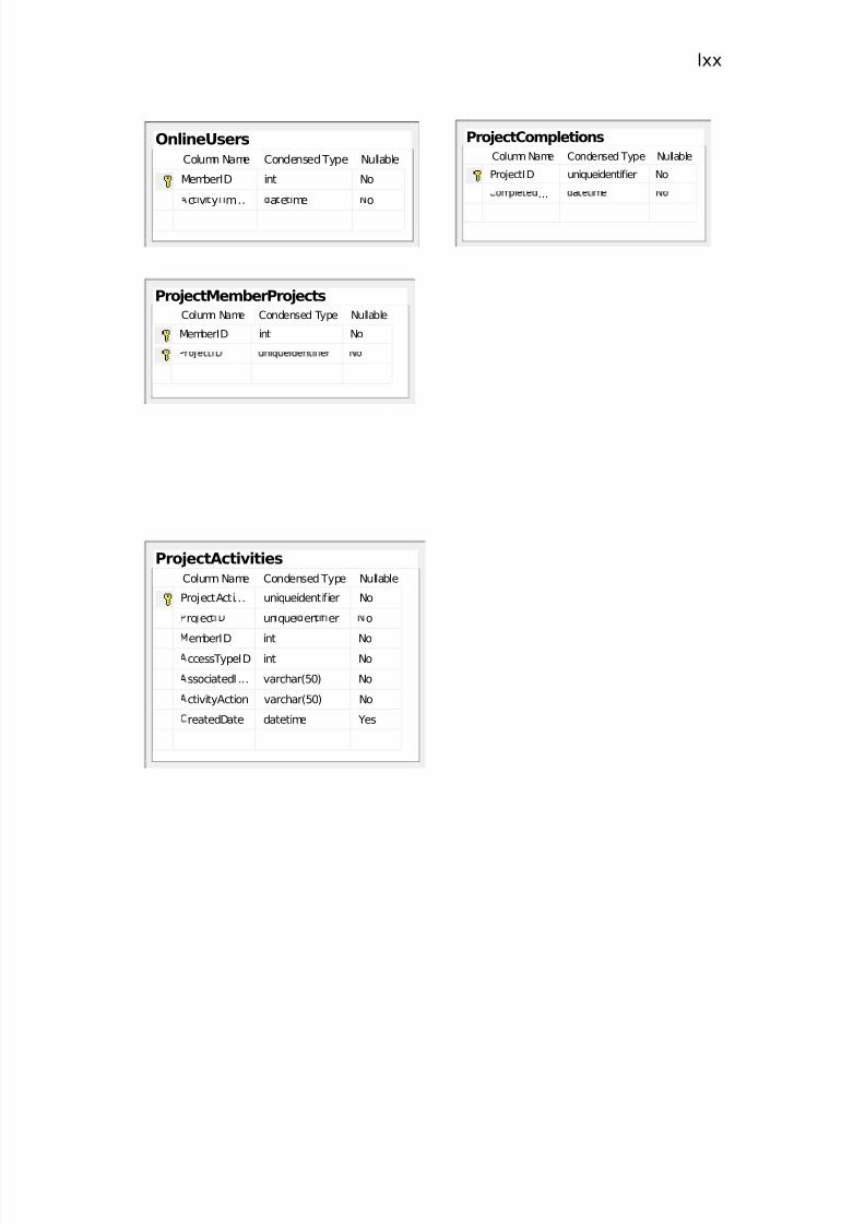


![[MS-RPL]: Report Page Layout (RPL) Binary Stream Format€¦ · MS-RPL] —. stream report. report page. report report report](https://static.documents.pub/doc/80x56/5fd9f7a7a90b7c34145fa364/ms-rpl-report-page-layout-rpl-binary-stream-format-ms-rpl-a-stream-report.jpg)


