48
Living With a Star Pre-Formulation Study Volume 2 Mission Concept Descriptions August 1, 2000 G O D D A R D S P A C E F L I G H T C E N T E R

Living With a Star
Pre-Formulation Study
Volume 2Mission Concept Descriptions
August 1, 2000
G O D D A R D S P A C E F L I G H T C E N T E R

AcknowledgementAcknowledgement
The Living With a Star (LWS) study management acknowledges with gratitude the significant contributions to this volume made by GSFC engineering team and Integrated Mission Design Center (IMDC) personnel.
A special note of thanks also goes to NASA Jet Propulsion Laboratorypersonnel who developed the concept for the Far Side Sentinel mission and provided timely input to the mission study team.
G O D D A R D S P A C E F L I G H T C E N T E R

OverviewOverview
This volume summarizes the results of a 6-month LWS pre-formulation study todevelop initial concepts for a set of missions that form the basis for the NASAproposed space weather research network.
Pre-formulation begins the process to define a viable and affordable concept for new NASA programs and projects. This step is followed by a more formal formulation phase to ensure that the program or project is ready to proceed into implementation.
The policy and process are defined in NPD 7120.4A and NPG 7120.5A.
G O D D A R D S P A C E F L I G H T C E N T E R

TraceabilityTraceability
A concerted effort has been made to maintain traceability of concepts and associated costs throughout the LWS program study. This added rigor willallow intelligent trade-offs to be performed and assessed as the program evolvesover the months and years ahead.
G O D D A R D S P A C E F L I G H T C E N T E R

Pre-Formulation ActivitiesPre-Formulation Activities
LWS pre-formulation activities, documented in the GSFC three-volume study summary, were undertaken to accomplish the following:
• Establish preliminary program/mission objectives• Develop initial concepts • Explore implementation and access to space options• Perform systems and supporting analyses • Identify driving requirements• Assess technology needs• Identify risks and mitigation strategies• Foster opportunities for partnering• Promote public outreach and education• Develop rough order of magnitude (ROM) costs• Report results of initial studies
G O D D A R D S P A C E F L I G H T C E N T E R

Study MethodologyStudy Methodology
The methodology adopted for the LWS study is illustrated in the diagram below. Program goals and objectives were first identified. Discipline science teams next determined the type, location, and frequency of measurements to be made. From this information, the engineering team then developed concepts for flight missions that would achieve desired results. Finally, full life-cycle costs were estimated for each mission. See Volume 3 for costing details.
OBJECTIVES
MEASUREMENTS
BENCHMARKING MISSIONS
CONCEPTUALIZATION IMDC COSTING
G O D D A R D S P A C E F L I G H T C E N T E R

Mission SetMission Set
As a result of a broad space weather program assessment of existing nationalassets (G. Withbroe et al), it was determined that certain key mission systemelements should be captured in the proposed NASA LWS program. These core missions are listed below and are described herein.
• Solar Dynamics Observatory --------------- Single Spacecraft• Radiation Belt Mappers --------------------- Small Constellation• Ionospheric Mappers ------------------------ Small Constellation• Inner Heliospheric Sentinels --------------- Small Constellation• Far Side Sentinel ----------------------------- Single Spacecraft
G O D D A R D S P A C E F L I G H T C E N T E R
PreamblePreamble
As illustrated in the Study Methodology flow chart, the engineeringteam in concert with the GSFC Integrated Mission Design Center (IMDC) developed an initial concept for each of the proposed LWSmissions.
IMDC results have been documented in CD ROM format and areavailable from the facility operations manager, E. Herring. The missionconcept descriptions, presented in what follows, are derivatives of thosedetailed studies and are suitable for general distribution.
Goddard Space Flight Center

Mission Study TemplateMission Study TemplateMission Study TemplateEach mission description includes the following set of charts as applicable:
•Title Page •Mission Profile •Mission Time Line •Mission Objectives •Instrument Complement •Instrument Parameters •System Synopsis •System Block Diagram •System Mass Summary •System Power Summary •Launch Profile •Orbit Pictorial •Orbit Parameters•Spacecraft Features ------------------------------------------------•Ground System Concept•Mission Operations•Science Data Distribution•Mission Specific Technology•Study Options•Preliminary Risk Assessment•Study Recommendations
Mechanical SubsystemLaunch Vehicle EvaluationLaunch ConfigurationOrbit ConfigurationPower SubsystemThermal SubsystemAttitude Control SubsystemPropulsion SubsystemC&DH SubsystemCommunications Subsystem
Goddard Space Flight Center

Solar Dynamics ObservatorySolar Dynamics Observatory
My friend, the sun, is here, but altered slightly;He acts more cooly than he has been doing;
He seems more distant, and he smiles less brightly.I wonder what is brewing.
In CoventryJ. J. Daly
I am also at this point accustomed to reaffirmwith emphasis my conviction that the sun is real, and also that it is hot--in fact hot as Hell, and that if the metaphysicians doubt it they should go there and see.
W. Churchill
G O D D A R D S P A C E F L I G H T C E N T E R

SDO Mission Profile
Launch Date: December, 2006Description: Continuous, high cadence observations of the full solar disk and coronal imaging in multiple wavelengths to improve understanding and forecasting of the Sun’s impact on our terrestrial environment
Instruments: Four instrument packages including a doppler/magnetograph, EUV and UV imagers, coronagraphs, and irradiance monitors
Spacecraft: A single, three-axis stabilized, solar-tracking spacecraft with low jitter that employs an apogee kick motor for orbit circularization and a propulsion system for station-keeping and disposal
Mission Life: 5 years
Orbit: Geosynchronous inclined at 28.5 degrees
Space Access: One launch from ETR to GTO on a Medium Class ELV
Key Technologies: Large format, fast read-out, CCDs and enhancing technologies at the subsystem or component level
G O D D A R D S P A C E F L I G H T C E N T E R
SDO Mission Time LineSDO Mission Time Line
• 15 months for instrument, spacecraft, and ground system accommodation studies as part of the initial project formulation effort
• 12 months for conclusion of project formulation and definitization prior to approval
• 4 years from approval to launch readiness• December 2006 launch• 5 years for baseline mission operations• 2-year mission extension (option for evaluation)
The following serial time spans are assumed for mission planning with July 1, 2000 as the initial reference date:
G O D D A R D S P A C E F L I G H T C E N T E R

SDO Mission ObjectivesSDO Mission Objectives
• Characterize the dynamic state of the Sun on temporal and spatial scales that enhance understanding of solar processes and space weather phenomena
• Explain the evolution, emergence, and decay of magnetic regions and their relationship to the onset of solar flares and coronal mass ejections
• Understand how solar activity affects irradiance and how changes in irradiance affect the Earth
• Improve the predictive capability of large-scale solar events
The SDO mission employs a three-axis stabilized spacecraft in a geosynchronous orbit with a complement of solar-pointed instruments to make continuous, high-cadence observations of the Sun from its subsurface layers to its outer atmosphere.
Specific mission objectives are as follows:
G O D D A R D S P A C E F L I G H T C E N T E R

SDO Instrument ComplementSDO Instrument Complement
The baseline SDO instrument complement has been arranged into four distinct measurement packages listed below.
(1) Helioseismic and Magnetic Field Imager (HMI) (2) Atmospheric Imager Assembly (AIA)(3) Coronal Imager Assembly (CIA)(4) Irradiance Monitors
Instrument system parameters, shown in the table that follows, are based on direct heritage from the SOHO, TRACE, Solar-B, and STEREO missions.
Accommodation of optional instruments including a spectroscopic imager and a soft x-ray imager with heritage from SOHO, Yohkoh, and GOES was also evaluated.
G O D D A R D S P A C E F L I G H T C E N T E R

SDO Baseline Instrument ComplementSDO Baseline Instrument Complement
Type/Classification Size Mass Power Data RateLWH or DH Avg/Peak Avg/Peak
(cm) (kg) (W) (kbps)HMI PackageDoppler Imager 40x50x90 24 25 27,000Magnetograph 15x15x70 Included 10 7,000Detector Package 5
AIA PackageEUV Imager 15x130* 57 35 68,000UV Imager/Filter Wheel 15x130 10 10 Included
CIA PackageInner Coronagraph 6x125 15 10 7,000Outer Coronagraph 12x125 20 10 7,000
Irradiance PackageIrradiance Monitor 15 30 0.5Optics Free Spectrometer 15x30 4 4 0.27
Total 150 134 116 Mbps
* For each of 6 telescope tubes
G O D D A R D S P A C E F L I G H T C E N T E R

• The nature of the mission requires continuous solar viewing and ground contact that is best accomplished from an inclined geosynchronous orbit.
• Continuous downlink of high-rate telemetry strongly influences the flight data and communications systems as well as the ground operations approach.
• A 5-year mission design life requires some level of system and subsystem redundancy.
• Accommodation of optical instruments with a pointing accuracy of 10 arc-seconds and low jitter places additional demands on spacecraft subsystems and the ground test program.
SDO System SynopsisSDO System Synopsis
G O D D A R D S P A C E F L I G H T C E N T E R

SDO System Block DiagramSDO System Block Diagram
HMI
AIA
CIA
IrradianceMonitors
InstrumentPackages
Gig
abit
Et h
e rn e
t (G
Ene
t)
Gigabit EthernetRouter
C&DH andACS
Calculations
ACEACE
ACS Actuator
ACS SensorACS Sensor
ACS WheelsACS Thrusters
ACS Sensor
S-bandTransponder
S-bandTransponder
omni
omni
Ka-bandTransmitter
Ka-bandTransmitter
GimbaledDish 1
GimbaledDish 2
GroundTestPort GEnet
GEnet
GEnet
GE
net
UDP/IP
TCP/IP
120 Mbpsdown
15 kbps down
2 kbps up
InstrumentCalculationsand Storage
Spacecraft Computer
Note: Shading indicates redundant components
G O D D A R D S P A C E F L I G H T C E N T E R

SDO Mass SummarySDO Mass Summary
Element Mass(kg)
Baseline Instruments 150Instrument Support Structure 50Modified RSDO Spacecraft Bus 400
Mechanical/Thermal 114Power 60Attitude Control 54Propulsion 61C&DH/Comm 72Harness 19AKM Adapter 10Balance Mass 10
Propellant 20AKM (STAR-30E) 668
Total 1288
Delta II 7925-9.5 Lift Capability to GTO 1869Launch Mass Margin 45%
AKM Capability to GEO 830Integrated Spacecraft-to-Orbit Margin 34%
Values are best estimates and do not include contingency.
G O D D A R D S P A C E F L I G H T C E N T E R

SDO Power SummarySDO Power Summary
Element Power(W)
Baseline Instruments 134Modified RSDO Spacecraft Bus 337
Thermal 50Power 21Attitude Control 84Propulsion 12C&DH 35Communications 112Harness 23
Total 471
Solar Array Capability (BOL) 1025Power Margin (BOL) 118%
Solar Array Capability (EOL) 920Power Margin (EOL) 95%
Values are best estimates and do
not include contingency.
G O D D A R D S P A C E F L I G H T C E N T E R

SDO Delta 7925 Launch ProfileSDO Delta 7925 Launch Profile
G O D D A R D S P A C E F L I G H T C E N T E R

SDO Orbit PictorialSDO Orbit Pictorial
AKM Burnto Circularize Orbit
Eastern RangeLaunch
GTO ~6-hour transit185 x 35,796 km
G O D D A R D S P A C E F L I G H T C E N T E R

The parameters for the final mission orbit are given below:
• Altitude: 35,796 km (Geosynchronous)• Inclination: 28.5° to the Equator• Longitude: 102° W• Period: 24 hours• Epoch: December, 2006• Right Ascension of the
Ascending Node (RAAN): 346°
SDO Orbit ParametersSDO Orbit Parameters
G O D D A R D S P A C E F L I G H T C E N T E R

SDO Shadow PeriodsSDO Shadow Periods
• There are two 3-week Earth shadow periods per year:– Maximum shadow duration: 73 minutes– Total duration for 1 year: 2701 minutes
• There are three Lunar shadow events per year:– Maximum shadow: 60%– Duration ranges from ≈ 27 to 30 minutes
G O D D A R D S P A C E F L I G H T C E N T E R

SDO Spacecraft FeaturesSDO Spacecraft Features
• A three-axis stabilized GEO bus from a future Rapid Spacecraft Development Office (RSDO) inventory with selective redundancy for critical functions
• Subsystem upgrades as appropriate to meet SDO performance and lifetime requirements
• Mission-unique accommodations including a stable support structure, a master control computer, and a large capacity image handling system for the instrument complement
• One standard observing mode for simplicity of operations
The major SDO features include:
G O D D A R D S P A C E F L I G H T C E N T E R
SDO Mechanical SubsystemSDO Mechanical Subsystem
• The SDO Mechanical Subsystem relies on standard aerospace materials and fabrication techniques for both spacecraft and instrument support structures. Aluminum and/or composites may be used to accommodate mass, thermal, or electrical constraints. Kinematic mounting of instruments is proposed in order to meet on-orbit alignment requirements.
• A number of critical deployments are required for the following elements:
- Folded solar array
- Gimbaled high-gain antennas
- Instrument covers
G O D D A R D S P A C E F L I G H T C E N T E R

SDO Launch Vehicle EvaluationSDO Launch Vehicle Evaluation
In an effort to minimize launch costs, the capability of several classes of launch vehicles to GTO was evaluated.
The chart on the left illustrates that the Taurus XL (3213) and Delta 7425-9.5(Lite 7426) do not have adequate liftcapability. Although not shown, theTaurus XL also does not meet SDOvolume requirements.
The Delta 7925-9.5 was thus chosenfor the concept study.
Launch Vehicle Performances
0
500
1000
1500
2000
TAURUS (GTO)3213
Delta Lite, 7426-9.5 (GTO)
Delta 7925-9.5(GTO)
Mass (
kg
)
Lift-off Mass for SDO
*
*Note: Performance quotes are based on expiring NASA ELV contracts and their associated numbering system. Future performance can be obtained through the NASA Launch Services (NLS) contract.
G O D D A R D S P A C E F L I G H T C E N T E R

SDO Launch ConfigurationSDO Launch Configuration
1.5m
1.6m
2m
Protective Cover(Removable)
Gimbaled High-Gain Antenna
Instrument Module(Thermal Shielding
Not Shown)
GEO Spacecraft
Delta 9.5 ft. (2.9 m) Fairing +X
G O D D A R D S P A C E F L I G H T C E N T E R

SDO Orbit ConfigurationSDO Orbit Configuration
Instrument Complement(cover/shielding removed for clarity)
Geo (RSDO) Spacecraft
Fixed Solar Array (2)
Thermal Panels (2)(shown, and far side)
Omni Antenna (2)(shown, and far side)
Gimbaled High-Gain Antenna (2)
G O D D A R D S P A C E F L I G H T C E N T E R

SDO Assembly SequenceSDO Assembly Sequence
G O D D A R D S P A C E F L I G H T C E N T E R
Instrument Support Structure (Typical)
Instrument Packages
Instrument Packages Integrated to Support Structure
Instrument Module Integrated onto Geo Bus

SDO Power SubsystemSDO Power Subsystem
The SDO Power Subsystem is a 28-volt direct energy transfer system that can support a load of 695 watts at the beginning of life. It consists of the following elements:
• Two fixed solar array wings with a total triple junction GaAs cell area of 4.5 m2
• A single 70 ampere-hour Li-ion battery sized to handle transfer orbit, worst-case shadow period, and peak power load conditions
• Power electronics
Solar array degradation over the life of the mission due to UV exposure,ionizing radiation, thermal cycling, and system losses has been taken intoaccount in the array sizing.
G O D D A R D S P A C E F L I G H T C E N T E R

SDO Power Subsystem (continued)SDO Power Subsystem (continued)
S DO Mis s ion Over 5 Yr Life With Deplo yable Pane l; 24% Eff Ce lls ; Average Lo ad During Day=694.2W; Average Load During
Night=694.2W
700
800
900
1000
1100
1200
1300
1400
0 365 730 1095 1460 1825
Mis s ion Time (Days )
Pow
er (W
atts
)
Daylight Average Solar Array Power Provided
Daylight Average Solar Array Power Required
Power Margin for 4.5-m2
Solar Array
Same Day and Night Power 695 Watts
G O D D A R D S P A C E F L I G H T C E N T E R
SDO Thermal SubsystemSDO Thermal Subsystem
• The instrument module, containing the scientific instruments and their support structure, is thermally isolated from the spacecraft bus.
• Standard techniques including multi-layer insulation blankets, coatings, heaters, fixed radiators, and heat pipes are used for thermal control of the instrument module.
• The instruments are mounted to a conductive support structure that is temperature controlled in the range of 0° to 20° C by an external radiator.
• Instrument electronics are maintained between 0° and 30° C.• Instrument CCDs are cooled to 200 K or lower by connecting them with heat
pipes to a separate radiator and have heater circuitry for precision control at the desired temperature.
• Spacecraft components are maintained between 0° and 40° C. Batteries, however, are kept between 0° and 20° C for long life.
• Heater power is provided for thermal control during eclipse seasons.
G O D D A R D S P A C E F L I G H T C E N T E R

The Attitude Control Subsystem (ACS) proposed for SDO can accommodate a number of solar viewing instruments with the following general pointing requirements:
• Accuracy (1 σ): - Pitch/Yaw: 10 arcsec
• Stability/Jitter (1 σ):- Pitch/Yaw: 0.25 arcsec over 45-second time interval- Roll: 50 arcsec over 45-second time interval
• Knowledge (1 σ):- Roll: 30 arcsec
SDO Attitude Control SubsystemSDO Attitude Control Subsystem
G O D D A R D S P A C E F L I G H T C E N T E R

SDO Attitude Control Subsystem (continued)SDO Attitude Control Subsystem (continued)
The ACS integrates the following complement of hardware to achieve the required pointing accuracy, stability/jitter, and knowledge:
• Redundant Attitude Control Electronics• Coarse Sun Sensors• Digital Sun Sensor• Four-Axis Inertial Reference Unit• Star Tracker• Pyramidal Reaction Wheel Assembly• Guide Telescope (part of instrument package)
G O D D A R D S P A C E F L I G H T C E N T E R
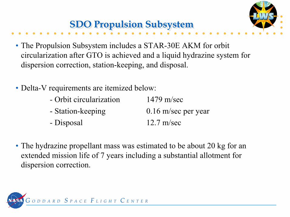
SDO Propulsion SubsystemSDO Propulsion Subsystem
• The Propulsion Subsystem includes a STAR-30E AKM for orbit circularization after GTO is achieved and a liquid hydrazine system for dispersion correction, station-keeping, and disposal.
• Delta-V requirements are itemized below:- Orbit circularization 1479 m/sec- Station-keeping 0.16 m/sec per year- Disposal 12.7 m/sec
• The hydrazine propellant mass was estimated to be about 20 kg for an extended mission life of 7 years including a substantial allotment for dispersion correction.
G O D D A R D S P A C E F L I G H T C E N T E R

SDO C&DH / Communications SubsystemSDO C&DH / Communications Subsystem
The SDO flight Command and Data Handling/Communications Subsystem has the following features:
• A spacecraft computer sized to accommodate the aggregate instrument data rate
• Two S-band transponders and omni-directional antennas for commanding, tracking, and low-rate telemetry as well as for spacecraft control in emergencies
• Two gimbaled 12-inch diameter Ka-band antennas for downlink of science data to avoid complex GEO maneuvers and to provide limited redundancy
• Convolutional and Reed-Solomon encoding• Data system bit error rate of 10-8
G O D D A R D S P A C E F L I G H T C E N T E R

SDO Communications SubsystemSDO Communications SubsystemS/
C O
BC
DigitalSwitch
DigitalSwitch
XPDR A
XPDR B
RFSwitch
HybridDivide
OMNI 1
OMNI 2
Ka Mod & Upconvert
RF Ka-band 12-inch diameter HGAs
Ka Mod & Upconvert
Ka-bandAmp
Ka-bandAmp
Ka
Switc
h
Gimbal KaAntenna 2
Gimbal KaAntenna 1
RF S-band CMD/TLM
CMD/TLM
Ka TLM
RF Ka-band TLM
RF S-band
Up/Down
G O D D A R D S P A C E F L I G H T C E N T E R

SDO Ground SystemSDO Ground System
The proposed ground system accommodations take advantage of existing infrastructure and include the following features:
• A dedicated 5-meter ground terminal at GSFC to ensure a continuous communications link
• Ranging from Deep Space Network (DSN)/Goldstone and Ground Network (GN)/Merritt Island Launch Annex (MILA) ground stations (two contacts/day) to minimize complexity at the prime site
• Distribution of data to three candidate locations:-50 Mbps to West Coast/U.S.-50 Mbps to East Coast/U.S.-25 Mbps to Middle U.S.
• Links and lines to achieve a data latency of minutes to hours
G O D D A R D S P A C E F L I G H T C E N T E R

SDO Ground System ConceptSDO Ground System Concept
DSN 26-m Station atGoldstone
andMILA 9-mStation
SDO MSOC
@ GSFC
50-Mbps Science Data
Middle U.S.
Housekeeping Telemetry @ 15 kbps
15 kbps Telemetry and Ranging
2-kbps Command
5-meter S/Ka-bandSystem @ GSFC
120 MbpsKa-band Down(Science Dataand Housekeeping)
Ranging through 26-m/9-m AntennasTwo passes per dayBack-up telemetry and command
East Coast
West Coast
50-Mbps Science Data
25-Mbps Science Data
ATMNetwork
S-band Command @ 2 kbps
G O D D A R D S P A C E F L I G H T C E N T E R

SDO Mission OperationsSDO Mission Operations
• Combined Mission and Science Operations Center (MSOC) co-located with dedicated ground station at GSFC
• Automated mission operations using COTS command and control system• Science data processed to Level Zero and short-term archival at MSOC• Real-time science data distribution to Principal Investigators (PIs) at East
Coast, West Coast, and Middle U.S. locations• On-board recording of health and safety data to support anomaly resolution• Hot backups for command/telemetry servers and MSOC science data
processor
A mission operations concept has been chosen that encourages automation ofroutine spacecraft functions and makes use of commercial off-the-shelf (COTS) products.
Salient features include the following:
G O D D A R D S P A C E F L I G H T C E N T E R

SDO Science Data DistributionSDO Science Data Distribution
MSOC(GSFC)
Science ATM
Network
ScienceData
Middle U.S. Institution
U. S. WestCoast
NGIXU. MD
U. S. EastCoast
Abilene(replaces
vBNS)
PIs &Co-PIs
OC3
OC3
OC3
OC12
Notes:
OC3 -155 Mbps
OC12-622 Mbps
G O D D A R D S P A C E F L I G H T C E N T E R

SDO Mission Specific TechnologySDO Mission Specific Technology
The SDO mission concept incorporates new technology that is expected to be available in the near term. Such items include:
• Radiation resistant, fast read-out, 4096 x 4096 monolithic CCD arrays• High-efficiency, triple-junction, GaAs solar cells• Li-ion battery• Small Explorer (SMEX)-Lite reaction wheels• Ka-band antenna system
G O D D A R D S P A C E F L I G H T C E N T E R
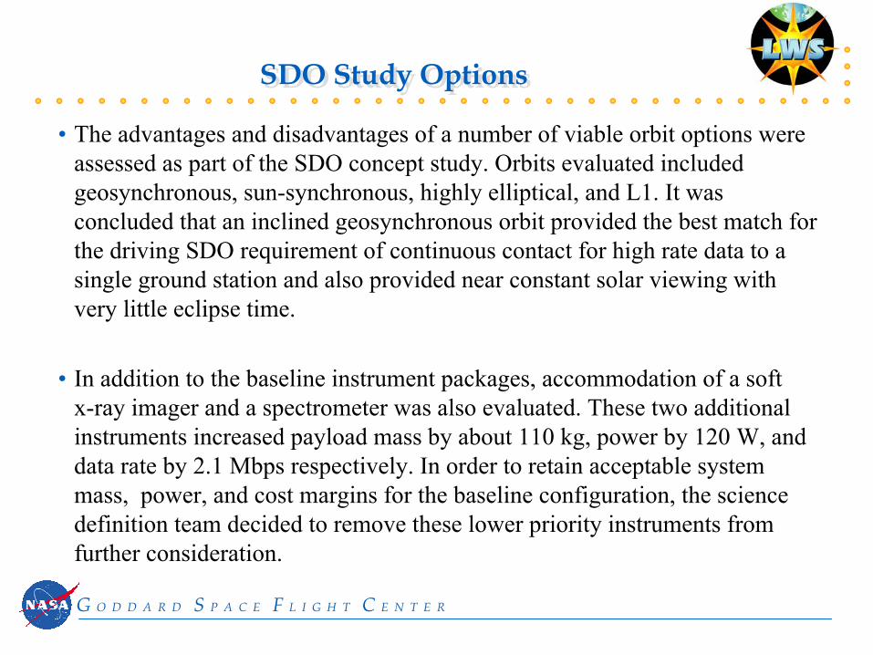
SDO Study OptionsSDO Study Options
• The advantages and disadvantages of a number of viable orbit options were assessed as part of the SDO concept study. Orbits evaluated included geosynchronous, sun-synchronous, highly elliptical, and L1. It was concluded that an inclined geosynchronous orbit provided the best match for the driving SDO requirement of continuous contact for high rate data to a single ground station and also provided near constant solar viewing with very little eclipse time.
• In addition to the baseline instrument packages, accommodation of a soft x-ray imager and a spectrometer was also evaluated. These two additional instruments increased payload mass by about 110 kg, power by 120 W, and data rate by 2.1 Mbps respectively. In order to retain acceptable system mass, power, and cost margins for the baseline configuration, the science definition team decided to remove these lower priority instruments from further consideration.
G O D D A R D S P A C E F L I G H T C E N T E R

Preliminary Risk AssessmentPreliminary Risk Assessment
During the course of the SDO concept study, a number of risk areas were identified and are listed below. Further study will be required to fully assess these risks, their potential impact, and mitigation strategies.
• Development of a robust flight data and image handling system • Development of a stable optical bench for the instrument packages• Maintenance of co-alignment of instruments with the inner coronagraph• Control of molecular and particulate contamination during ground testing and
flight operations• Spin balancing of the integrated system as required for Delta 3rd stage and
AKM launch phases• Availability of anticipated technology enhancements
G O D D A R D S P A C E F L I G H T C E N T E R

SDO Study RecommendationsSDO Study Recommendations
• Conduct a survey of solar viewing instruments now under development or planned for future development to ensure adequacy of assumed SDOinstrument resource requirements.
• Develop an initial set of requirements for the Instrument Support Structure.• Perform an accommodation study to determine the suitability of RSDO
spacecraft for the SDO mission.• Outline the functions to be performed by the master computer and size the
image handling system. • Determine the proper balance between on-board and on-ground instrument
data processing.• Assess the ability of soft x-ray imagers and spectrometers planned for other
flight missions to complement the SDO baseline measurements.
G O D D A R D S P A C E F L I G H T C E N T E R

AcronymsAcronyms
ACE Attitude Control ElectronicsACS Attitude Control SubsystemAIA Atmospheric Imager AssemblyAKM Apogee Kick MotorBOL Beginning Of LifeC&DH Command and Data HandlingCCD Charge-Coupled DeviceCIA Coronal Imager AssemblyCOTS Commercial Off-The-ShelfDSN Deep Space NetworkELV Expendable Launch VehicleEOL End Of LifeETR Eastern Test Range
G O D D A R D S P A C E F L I G H T C E N T E R

AcronymsAcronyms
EUV Extreme UltravioletGaAs Gallium ArsenideGN Ground NetworkGOES Geosynchronous Operational Environmental SatelliteGSFC Goddard Space Flight CenterGTO Geosynchronous Transfer OrbitHMI Helioseismic and Magnetic Field ImagerLWS Living With a StarMECO Main Engine Cut-OffMILA Merritt Island Launch AnnexMSOC Mission and Science Operations CenterNLS NASA Launch ServicesOBC Onboard Computer
G O D D A R D S P A C E F L I G H T C E N T E R

AcronymsAcronyms
PI Principal InvestigatorRAAN Right Ascension of the Ascending NodeRF Radio FrequencyRSDO Rapid Spacecraft Development OfficeSDO Solar Dynamics ObservatorySECO Secondary Engine Cut-OffSMEX Small ExplorerSOHO Solar and Heliospheric ObservatorySRM Solid Rocket MotorSTEREO Solar Terrestrial Relations ObservatoryTRACE Transition Region And Coronal ExplorerUV UltravioletXPDR Transponder
G O D D A R D S P A C E F L I G H T C E N T E R


