LJ$H& QO.t. ':7"L".k DBRIENCGERE [ O&er: -M&L ENGINEERS, INC September 17, 1996 Mr. David O. Lederer Remedial Project Manager Waste Management Division - HRS-CAN3 U.S. ENVIRONMENTAL PROTECTION AGENCY Massachusetts Superfund Section JFK Federal Building Boston, MA 02203 RE: Sullivan's Ledge Superfund Site FILE: 5509.003 SUBJ: Slurry Well Conceptual Ap- proach Dear Dave: As described in our letter dated September 10, 1996, this letter presents a conceptual approach for the slurry wall to be installed at the subject site. Specifically, the following topics are discussed: • Slurry wall draft horizontal alignment • Slurry wall design criteria • Ground water collection trench design, operation, and monitoring. SLURRY WALL DRAFT HORIZONTAL ALIGNMENT The proposed draft horizontal alignment for the slurry wall is shown on Figure 1. The development of the proposed alignment considered the following factors: Required setback from Hathaway Road: Calculations are attached which indicate that a 10-ft setback from Hathaway Road will be required based on road stability requirements. Stability of cap: Calculations are attached which indicate that cap stability will not be adversely impacted by the slurry wall. Area for work platform: A work platform for the slurry wall will be required during construction. Work platforms typically consist of a reinforced access road on either side of the slurry wall, extending approximately 10 to 15 ft from the slurry wall center line. The area for the work platform is shown on Figure 1. Required clearance for construction equipment: The required clearance for construction equipment will be met with the with the work platform described above and the traffic control described below. O'Brien & Gere Engineers. Inc., an O'Brien & Gere Company 1200 Crown Colony Drive / Quincy, MA 02169 / (617) 479-1313 FAX (617) 4/9-1397 and offices in major U.S cities
Transcript
LJ$H& QO.t. ':7"L".k
DBRIENCGERE [ O&er: -M&L ENGINEERS, INC
September 17, 1996
Mr. David O. Lederer Remedial Project Manager Waste Management Division - HRS-CAN3 U.S. ENVIRONMENTAL PROTECTION AGENCY Massachusetts Superfund Section JFK Federal Building Boston, MA 02203
RE: Sullivan's Ledge Superfund Site FILE: 5509.003 SUBJ: Slurry Well Conceptual Ap
proach
Dear Dave:
As described in our letter dated September 10, 1996, this letter presents a conceptual approach for the slurry wall to be installed at the subject site. Specifically, the following topics are discussed:
• Slurry wall draft horizontal alignment • Slurry wall design criteria • Ground water collection trench design, operation, and monitoring.
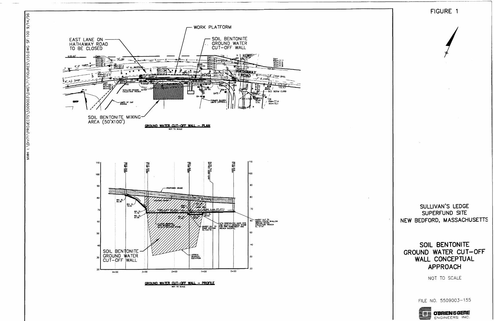
SLURRY WALL DRAFT HORIZONTAL ALIGNMENT The proposed draft horizontal alignment for the slurry wall is shown on Figure 1. The development of the proposed alignment considered the following factors:
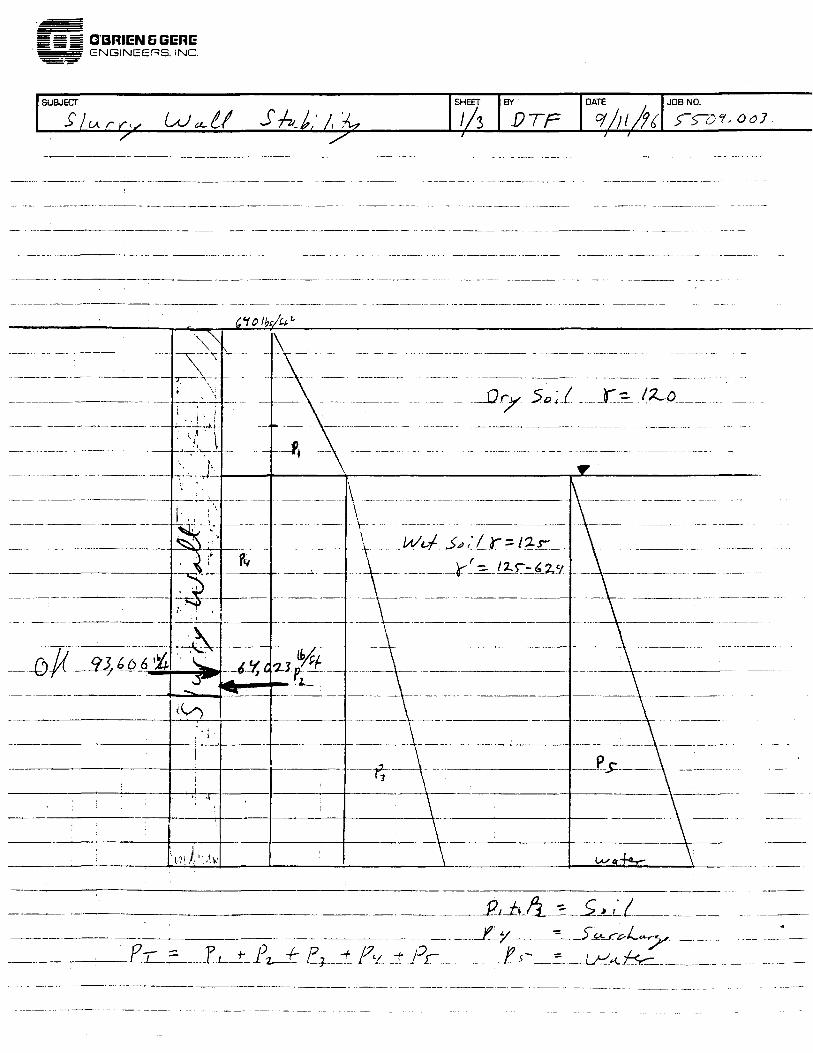
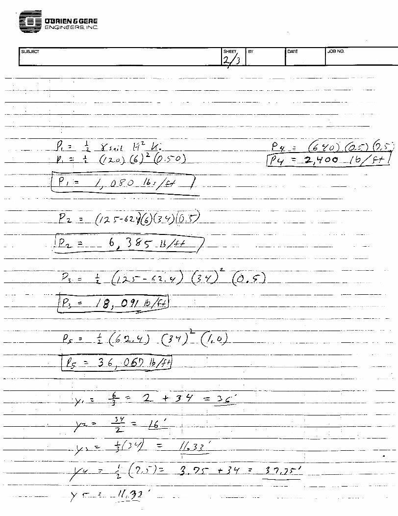
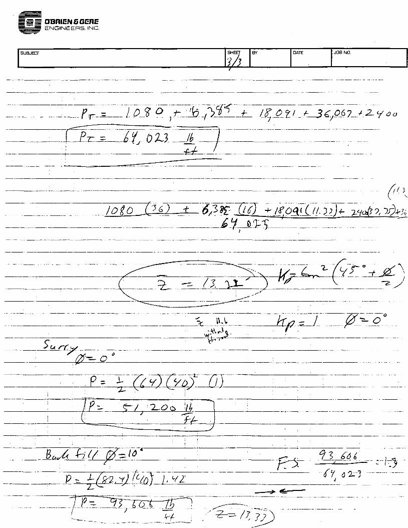
Required setback from Hathaway Road: Calculations are attached which indicate that a 10-ft setback from Hathaway Road will be required based on road stability requirements.
Stability of cap: Calculations are attached which indicate that cap stability will not be adversely impacted by the slurry wall.
Area for work platform: A work platform for the slurry wall will be required during construction. Work platforms typically consist of a reinforced access road on either side of the slurry wall, extending approximately 10 to 15 ft from the slurry wall center line. The area for the work platform is shown on Figure 1.
Required clearance for construction equipment: The required clearance for construction equipment will be met with the with the work platform described above and the traffic control described below.
O'Brien & Gere Engineers. Inc., an O'Brien & Gere Company 1200 Crown Colony Drive / Quincy, MA 02169 / (617) 479-1313 FAX (617) 4/9-1397
and offices in major U.S cities
Mr. David Lederer September 17, 1996 Page 2
Traffic control requirements: Based on the area required for the work platform and the required clearance for construction equipment, it will be necessary to temporarily close the eastbound lane of Hathaway Road during construction. Construction of the slurry wall is anticipated to require 4 to 6 weeks, based on five 8-hr work days per week.
Location of subsurface utilities: Based on a review of the site survey, the following utilities are either beneath Hathaway Road or north of it: sanitary, water, gas, and storm. It is not anticipated that these utilities will be impacted by construction of a slurry wall. One fire hydrant, with its associated lateral piping, will have to be temporarily removed or relocated during construction. The hydrant is shown on Figure 1.
Area for mixing plant: An area for the slurry mixing plant is shown on Figure 1.
Area for spoils management: Spoils associated with construction of the slurry wall will be managed within the limits of the cap system.
SLURRY WALL DESIGN CRITERIA
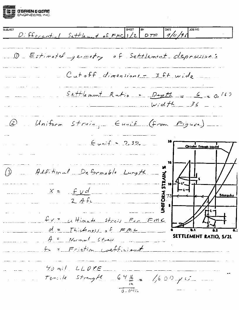
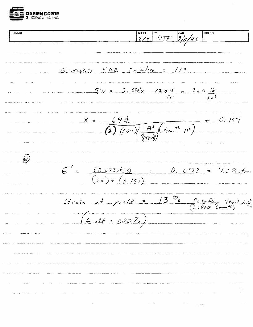
The ground water cutoff wall will consist of a soil bentonite slurry wall installed below the cap system down gradient of and between stations 0+94 and 3+00 of the east-west shallow ground water collection trench. The soil bentonite slurry wall will be 3 ft wide and will extend to competent bedrock. The maximum permeability of the slurry backfill will be 1 X 10⁻⁷ cm/sec. The soil-bentonite slurry backfill will consist of 5% bentonite; site soils will be used in the slurry backfill.
GROUND WATER COLLECTION TRENCH DESIGN, OPERATION AND MONITORING
Ground Water Collection Trench Design: The ground water collection trench will be located parallel to and on the up gradient site of the slurry wall, approximately 10 ft from it. The elevation of the ground water collection trench piping will be as presented in the 95% design submittal. Specifically, one leg of the collection pipe will be set at approximately 67 ft, while the other leg of the collection pipe will be set at approximately 66 ft.
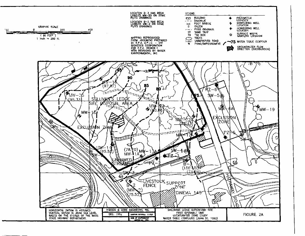
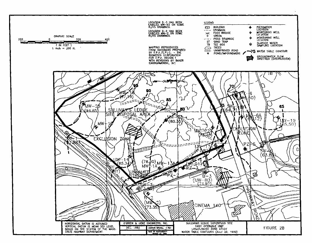
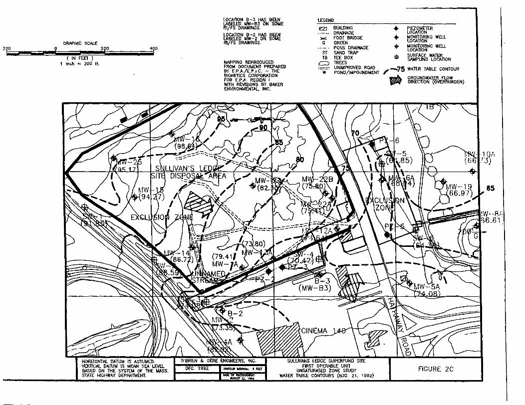
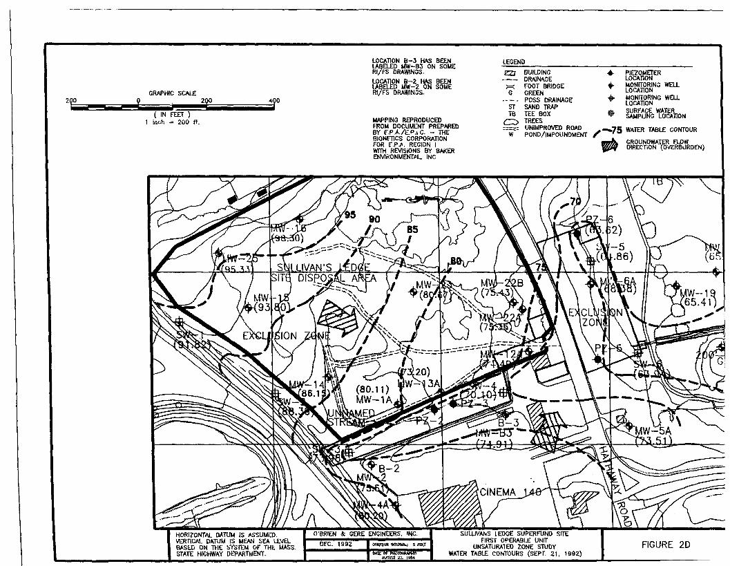
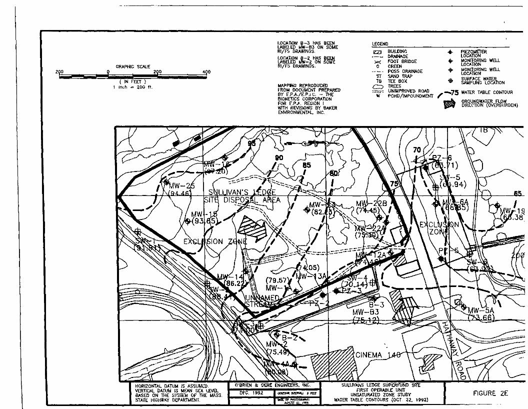
The elevation of 67 ft is approximately 10 to 15 ft below the top of the proposed slurry wall, and is equal to or lower than the water table elevations observed historically in shallow wells and piezometers immediately north of Hathaway Road. Figure 2 in the December 1992 Unsaturated Zone Study Report presents seasonal low ground water elevations (attached). The elevation of 67 ft is lower than the ground water elevations north of Hathaway Road. Likewise, Table 3-1D from the 1993 Ground Water Trend Analysis Report presents elevation data from monitoring well 6A, which is immediately north of Hathaway Road. For seven sampling events between 1985 and 1993, ground water elevations in this well ranged from 69.00 to 67.87 ft, and averaged 68.25 ft.
O BRIEM £k oERE ENG MEERS
Mr. David Lederer September 17, 1996 Page 3
Ground Water Collection Trench Operation: Water levels in the ground water collection trench will be initially maintained at approximately 73 to 75 ft, which represents the current elevation of shallow ground water at the down gradient side of the Disposal Area. The long-term elevation maintained in the collection trench will be adjusted based on monitoring conducted to evaluate the effectiveness of the trench, as described below.
Slurry Wall/Ground Water Collection Trench Monitoring: The effectiveness of the slurry wall/ground water collection trench system will be monitored at two locations along the length of the system. At each location, one pair of piezometers (one shallow, one deep) will be placed approximately 5 ft up gradient of the collection trench, and one pair of piezometers (one shallow, one deep) will be placed approximately 5 to 10 ft down gradient of the slurry wall. A total of four shallow and four deep piezometers will be installed. Shallow piezometers will be screened at elevation 60 to 70 ft; deep piezometers will be screened in the range of 5 to 15 ft above the top of the bedrock surface. The shallow piezometers will document the effectiveness of the ground water collection trench. The shallow and deep piezometers will document the effectiveness of the slurry wall throughout the full depth of the wall. In addition to the piezometers, water levels in the collection trench itself will be monitored at the collection trench manholes.
Water levels in the piezometers and the collection trench will be collected on a quarterly basis. The data will be used in the short term to document the changes to the site hydrogeology caused by the slurry wall/ground water collection system. An evaluation of the long-term effectiveness of the system, however, will not be appropriate until the site hydrogeology equlibrates to the new conditions. This period of equilibrium may last one to two years after the site has been capped, and precipitation recharge to the overburden has been reduced. The evaluation of long-term effectiveness will consider the following factors:
Comparison of ground water elevations across the site as well as comparisons to historical data.
Ground water elevation data in the piezometers adjacent to the slurry wall drain
Trends in ground water quality.
Discharge rates and volumes from the shallow collection trench
Improvements in down gradient ground water quality, or evidence of hydraulic containment by up gradient and down gradient ground water elevations will be indicative of the effectiveness of the ground water collection trench/slurry wall system.
Mr. David Lederer September 17, 1996 Page 4
SUMMARY
As we discussed, we would like to meet with you to discuss this letter. Please call me to arrange a date and time.
Very truly yours,
O'BRIEN & GERE ENGINEERS, INC.
Imes M. O'Loughlin, PE Senior Project Engineer
s!27 Iedere3 let
cc: A. Carreiro G. Garfield D. Connors G. Gifford D. Dwight T. Jordan D. Farber J. Naperstek M. Fontaine
O'BRIEN S. JERE E'JGIMEit
EAST LANE ON - HATHAWAY ROAD TO BE CLOSED
63512'
~
I" /<.:)
~ Cl /I") 0 0 ()) --,0 L[) II)
/(/) 1- SOIL BENTONITE MIXING u w AREA (50'X1 oo'),
PLATFORM
SOIL BENTONITE GROUND WATER CUT-OFF WALL
I
0 QRAYNP· WAJEB QJI-AEE I& - Pl-Ni NOT TO SCAU:0::
a.. / I" > Cl /
110
100
9090
ao80
7070
N\OT our TO ~1H-S0U1H SHAU.OW60
NO WAlER COULCTION 11l£NCH EL. 67.97
50so
4040
30
20 4+00 o+oo
QRAYNP WAJEB QJJ-AEE I& - PBAEJL,E NOT TO SCAU:
SOIL BEN ONITE GROUND ATER CUT-OFF WALL
;~<
i'" I
F I
3+00 2+00 1+00
.. :I:+ 2 ... i!s :,:
110
100
30
20
FIGURE 1
SULLIVAN'S LEDGE SUPERFUND SITE
NEW BEDFORD, MASSACHUSETTS
SOIL BENTONITE GROUND WATER CUT-OFF
WALL CONCEPTUAL APPROACH
NOT TO SCALE
FILE NO. 5509003-155
D'BRIENBGERE ENGINEERS INC.
---------------------===~·~-···---·
(0 (1)
'-.. (0
" m ~
i.;.: (/)
(.'.)
3: , J
q (0 U')
/(/) w a:: ::::, (.'.)
G: / r-... / I 0::: Iw w 0::: _Jl.J... 0 w(.'.) I- w _J WUzu<( z3: 0 - I-<( 1---zwz0 0 :J Z<(3 <CwLw/ w 0::: 03I") C) 3: 0:::wl..J...> I- l..J... I 0 >I 0 >0 zoLJ... <( 0~<( 0:::m w zz0...0 z ~zOw3U') :::J 0_J . ::) I 0...<(U') l..J..._JO I- Ot=0/ I 0z - 0:::::) 0::: u(/) 0:::I I C)W_J() wLIMIT~<(
~C)U
C) _Jw, I <(
OF CAP Q0 a:: 81 81Q_
/ r::. CAP ACCESS ROAD > i:i EMBANKMENT DRAINAGE SWALE/ - MATERIAL I SEED--~3: :::E EMBANKMENT
LOCA!lON i3- 3 HAS BEEN IF.GENO l}.'fl_EO MW-B3 ON SOME Rf F5 DRAWINGS. P2J BUILDING PIEZCMCTlR
DRA!NAuE LCCATIC~•LOCATION B-2 ~ BEtN ~..., IJ.ONITCR!NG WELLlABREO tJ.W-2 N S0!.1E FCCT BRIOGI:'. + LOCATIONGRAPHIC SCALE PI/FS DRAV1INGS. G GREEN
IAONITORING wru2()0
~
POSS DRAINAGl: ..0 -4'(0 LCCATimtSi SAND TR.!P"k l- SURFACE WAFR-= ( IN FtFT ) Ti3 ,..EE BOX iv SAUPU'.IIG LOCAllON
M,\PPING REPROOUCtm TREf.SI inch "' 200 ft c:::>FROM JOCUM[NT PREPARED UN!Mi'RO'IEO ROAD / -75 W!,TER TABLE CCNT,"lURBY f.P.A.. E.P.1.C. - THE w l'OND/IMPOUNOMfrlfBIONETICS CORPORATION FOR f.P ..&. REGION I - G~OUNDY/J..T(lt FLOW01 ECTIOtl OVERBURDEN)VllTH REVISIONS BY BAKER ENV!RONIAENT.&l, INC
HORIZONTAL DATUM IS ASSUM[[). SU~J..NS l£DGE SVPERFUN::> SITE VERTICAL DATUIA IS ."11:AN SEA l£VB. FlRST O?ERABLc UNITDEC. i99L FIGURE. 2ABAS[O Oto: THE S"'!ST1::U OF THE W.SS. U:l:..ATUR.6TED ZONE ::lUDY STATE HIGHWAY DEPmTIAENT. WATER TABLE CONTOURS (JlllfE 30, 1!)92)
LOCATION B··J HAS BEEN LEGEND lA~ELEO MW-B3 ON SOME Ri FS DRAWINGS. a.I BUILDING ... PIEZOME1ER
DRAINAGE LOCI\TIONl£CATION B-2 HAS BEEN MONITORING WEU.BEl.£0 MW-2 ON SOME )::{ F'OOT BRIDGE ..
Lo::AllONGRAPHIC SC.t.LE RI/FS DRAWINGS. G CREOI • IJONITORING WEU.POSS DRAINAGE490 LO·::ATION2Yb y 2QOI ST SAND TRAP SL,RFACE WATER
( IN FEET" ) SAUPUNG LOCATIONTB TEE BOX $ MAPPING REPRODUCED TREES1 inch = 200 fl. c:::>FROM DOCUMl:NT PREPARED UNIMPROVED ROAD /-75 WATER TABLE CONTOURBY f.P.A./E.P.1C. - THE w PONO/IMPOUNDMENlBIONETICS CORPORATION GROUNDWAlfcR FLOWFOR E".PJ\. REGION I DIRECTION OVERBURDEN)vJtWITH REVISIONS BY BAKER ENVIRONMENT.&!.. !N:
HORIZONTAi.. DATUM IS ASSUM[!). Vt.lmC/.J... DATUM IS MEAN SEJ.. LEVE\.. BASED ON THE SYSTEM OF THE MASS. STATE HIGHWAY DEPARTMENT.
SUU.IV~S l£DG( SUPERFUIIO SITE F1RST OPERABLE UNIT
l.NSATt.;RATED ZONE STUDY FIGURE 28 WATER TABLE COtffOURS (JliLY 20, •992)
LOCATION B-3 HAS BEEN LEGEND lAJiEl.ED MW-BJ ON SOME RI FS DRAWINGS. e:zJ BUILDING ... PIEZOMETER
DRAINAGE LOCATIONLOCATION B-2 HAS B~ MONITORING Will)=( FOOT BRIDGE ..LA~D MW-2 ON SOE LO<'-ATIONGRAPHIC SCALE RI FS DRAWINGS. G GREEN
MONITORING WlliPOSS DRAINAGE ... 2?0 2QO LOC'.ATIONQ I "YD ST SAND TRAP SURFACE WATER
( IN FEET ) TB TEE BOX SAMPLING LOC'-ATIONMAPPING REPRODUCED TREES1 inc.h "' 200 rt. c:::> * ~OM DOCUMl:NT PREPARED UNIMPROVED ROAD BY E.P .A./E.P .1 C. - THE w POND/IMPOUNDMENT
/'-75 WATER TABLE CONTOUR BIONETICS CORPORATION FOR E.P>. REGION I - GROUNDWAT~ ~OWDIRECTION OVER URDEN)WITH REVISIONS BY BAKER ENVIRONMENT.al., INC.
HORIZONTAL DATUM IS ASSUM[O. VERTICAL DATUM IS MEAN SEA LEVEL BASED ON THE SYSTEM OF THE MASS. STATE HIGHWAY DEPARTMENT.
SULLIVANS lEDGE SUP£RFUNO SITE FlRST OPERABLE UNIT
UNSATURATED ZONE STUDY FIGURE 2C WATER TABLE CONTOURS (AUG. 21, 1992)
85
LOCATION B-3 Hf\S BEEN LEGENDlAfJELED MW-BJ ON SOME RljFS DRAWINOS. 1?:ZJ BUILDING ... PJEZOMETE'R
LOCATIONDRAINAGE LABELED MW-2 ON SOME :,=::: FOOT BRIDGE .. MONITORING WELLLOCATION B-2 HAS BEEN
LOCATIONGRAPHIC SCALE RI/FS DRAWINuS. G GREEN MONITORING wru..POSS DRAINAGE, 2QO LOC'.ATIONQ ST SAND TRAP SURFACE WATER
( IN fEEl" ) TS TEE BOX SAMPLING LOC'.ATION I itwh ~ 200 ft. C) TREES *MAPPING REPRODUCED
FROM DOCUMDIT PREPARED UNIMPROVED ROADBY E.P.A./E.P.1 C. - THE /-75 WATER TABLE CONTOUR
W POND/IMPOUNDMEtfl'BIONETICS CORPORATION ~ GROUNDWAT~~ FLOWFOR f.P..A. REGION I 1flf' DIRECTiON (OVERBURDEN)WITH REVISIONS BY BAKER ENVIRONMENTAL INC.
SUWVANS LEDGE SUPERFUND SITE VERTICAL DAnJM IS MEAN SEA u:vEL FIRST OPERAS!£ UNIT BASED ON THE SYS~"M OF TH£ MASS. UNSATURATED ZONE STUDY
LOCATION B-3 HAS BEEN LABaEO IAW-B3 ON SOME RI/FS DRA1MNGS.
LOCATION B-2 HAS BEEN LABaED IAW-2 ON SOME Rl/fS DRAWINGS.
M.APPING REPRODUCED FROM DOCUMCNT PREPARED BY f.P.A/E.P.1 c. - THE BIONETICS CORPORATION FOR f.P.>'. REGION I WITH REVISIONS BY BAKER ENVIRONMENTAL. INC.