86
LM Basic (408e/412e) OPERATOR ’ S MANUAL

LM Basic (408e/412e)
OPERATOR’S MANUAL

SATO International Pte Ltd
438A Alexandra Road #05-01/02
Alexandra TechnoparkSingapore 119967Tel: (65) 6271 2122Fax: (65) 6271 2151
Email: [email protected]
Be sure to ask your dealer about our maintenance contracts
to ensure peace of mind during your usage of SATO products
Version: SI-LM4xxe-01rA-16-01-OM
© Copyright 1994 – 2006
SATO International
Warning: This equipment complies with the requirements in Part 15 of FCC rules for a Class A computing device. Operation of this equipment in a residential area may cause unacceptable interference to radio and TV reception requiring the operator to take whatever steps are necessary to correct the interference.
All rights reserved. No part of this document may be reproduced or issued to third parties in any form whatsoever without the express permission of SATO. The materials in this document are provided for general information and are subject to change without notice. SATO assumes no responsibilities for any errors that may appear.
1
TABLE OF CONTENTS1. OVERVIEW
1.1 General Specifications ........................................................................................ 1-2
2. INSTALLATIONSafety Precautions..................................................................................................... 2-22.1 Unpacking............................................................................................................. 2-42.1.1 Included Accessories ....................................................................................... 2-52.1.2 Parts Identification............................................................................................ 2-62.2 Loading the Carbon Ribbon................................................................................ 2-82.3 Loading Labels..................................................................................................... 2-9
2.3.1 Loading Roll Paper ........................................................................................ 2-102.3.2 Loading Fanfold Paper .................................................................................. 2-112.3.3 Adjusting the Paper Sensor ............................................................................. 2-12
2.4 Replacing the Print Head .................................................................................... 2-13
3. CONFIGURATION AND OPERATION3.1 Operating Modes.................................................................................................. 3-13.2 The Operation Panel ............................................................................................ 3-23.3 Accessing the Various PRINTER MODES ......................................................... 3-33.3.2 Overview of LCD Menu Options In Various Modes ....................................... 3-53.4 NORMAL Modes................................................................................................... 3-8
3.4.1 Online ............................................................................................................. 3-83.4.2 Offline .............................................................................................................. 3-83.4.3 Print Darkness ................................................................................................. 3-83.4.4 Print Speed ...................................................................................................... 3-93.4.4 Pitch Offset ...................................................................................................... 3-93.4.5 Cancel Print Job .............................................................................................. 3-9
3.5 ADVANCED Mode ................................................................................................ 3-103.5.1 Advanced ....................................................................................................... 3-103.5.2 Darkness Range ............................................................................................. 3-103.5.3 Zero Slash ....................................................................................................... 3-103.5.4 Auto Online ...................................................................................................... 3-103.5.5 Print Offset ....................................................................................................... 3-10
3.5 Advanced Mode (cont’d) ..................................................................................... 3-113.5.6 Set Calendar .................................................................................................... 3-11
3.6 SERVICE Mode..................................................................................................... 3-123.6.1 Service ........................................................................................................... 3-123.6.2 Slice Level ...................................................................................................... 3-123.6.3 Auto Line Feed ................................................................................................ 3-123.6.4 Feed On Error .................................................................................................. 3-123.6.5 Reprint W/Feed ................................................................................................ 3-123.6.6 Forward/Backfeed Amount ............................................................................. 3-13
2
3.6.7 Euro Code ....................................................................................................... 3-133.6.8 Select Language .............................................................................................. 3-133.6.9 Command or LCD Priority ................................................................................ 3-133.6.10 Ignore CAN/DLE ............................................................................................ 3-133.6.11 Ribbon Near End On/Off ................................................................................ 3-143.6.12 IEEE1284 ACK Signal ................................................................................... 3-143.6.13 Backfeed Speed ............................................................................................ 3-14
3.7 COUNTERS Mode ................................................................................................ 3-153.7.1 Counters ........................................................................................................ 3-153.7.2 Counter Select ................................................................................................ 3-153.7.3 Show Head Counter ........................................................................................ 3-153.7.4 Clear Head Counter ......................................................................................... 3-153.7.5 Show Life Counter ........................................................................................... 3-15
3.8 MOVE Mode .......................................................................................................... 3-163.8.1 Movements of Labels ....................................................................................... 3-163.8.2 Move Mode ..................................................................................................... 3-163.8.3 Pitch Sensor .................................................................................................... 3-16
3.9 TEST PRINT Mode................................................................................................ 3-173.9.1 Select Test Print .............................................................................................. 3-173.9.2 Test Print Size ................................................................................................ 3-173.9.3 Print Size ......................................................................................................... 3-173.9.3 Start/Stop Test Print ........................................................................................ 3-17
3.10 DEFAULT SETTING Mode ................................................................................. 3-183.10.1 Resetting the Printer ...................................................................................... 3-183.10.2 Reset Completed ......................................................................................... 3-18
3.11 Protocol Storing................................................................................................. 3-193.11.1 Protocol Download ......................................................................................... 3-193.11.2 Loading Completed ....................................................................................... 3-193.11.3 Initialization of Protocol Code ........................................................................ 3-19
3.12 MAINTENANCE Mode ........................................................................................ 3-203.12.1 Factory or All Clear Mode ............................................................................ 3-203.12.2 Factory Mode ................................................................................................ 3-203.12.3 Test-Print Width ............................................................................................ 3-203.12.4 Start/Stop Test Print ...................................................................................... 3-203.12.5 All Clear Mode ............................................................................................. 3-213.12.6 Counter/EEPROM clear ................................................................................. 3-213.12.7 Clear Confirmation ......................................................................................... 3-21
3.13 HEX DUMP Mode................................................................................................ 3-223.13.1 LCD Status .................................................................................................. 3-223.13.2 Hex Dump Mode in buffer .............................................................................. 3-22
3.14 DOWNLOAD Mode ............................................................................................. 3-233.14.1 LCD Status .................................................................................................. 3-23
3.15 BOOT DOWNLOAD Mode.................................................................................. 3-243.15.1 LCD Status .................................................................................................. 3-24
3
TABLE OF CONTENTS (CON’TD)
4. CLEANING AND MAINTENANCE4.1 Introduction .......................................................................................................... 4-14.2 Cleaning The Print Head, Platen and Rollers .................................................... 4-14.3 How To Clean The Printer (With A Cleaning Set).............................................. 4-24.4 How To Clean The Printer (Cleaning Sheet) ...................................................... 4-34.5 Adjusting Print Quality ........................................................................................ 4-4
4.5.1 Adjusting Print Darkness ................................................................................. 4-44.5.2 Adjusting Print Speed ...................................................................................... 4-5
4.6 Replacing A Blown Fuse ..................................................................................... 4-5
5. INTERFACE SPECIFICATIONS5.1 Interface types...................................................................................................... 5-15.2 Interface Card DIP SWITCH Settings (RS-232C) ............................................... 5-25.3 Interface Card DIP SWITCH Settings (LAN)....................................................... 5-35.4 Interface Card DIP SWITCH Settings (Wireless LAN)....................................... 5-35.5 External Signal Interface ..................................................................................... 5-45.6 Serial Interface Specifications (RS-232C).......................................................... 5-45.7 READY/BUSY ....................................................................................................... 5-55.8 Single Job Buffer ................................................................................................. 5-65.9 Multi Job Buffer.................................................................................................... 5-75.10 X-ON/X-OFF ........................................................................................................ 5-75.11 Single Job Buffer ............................................................................................... 5-95.12 Multi Job Buffer.................................................................................................. 5-105.13 IEEE 1284 Interface............................................................................................ 5-115.13 Interface Signals ................................................................................................ 5-135.14 Single Job Buffer ............................................................................................... 5-145.15 Multi Job Buffer.................................................................................................. 5-16
6. TROUBLESHOOTING6.1 Initial Checklist..................................................................................................... 6-16.2 Using the RS232C (SERIAL) Interface ............................................................... 6-26.3 Understanding the LCD Error Messages........................................................... 6-36.4 Troubleshooting Guide ....................................................................................... 6-4

4
TABLE OF CONTENTS (CON’TD)
7. OPTIONAL ACCESSORIES7.1 Introduction .......................................................................................................... 7-17.2 Available Interface Boards.................................................................................. 7-17.3 Optional Accessories: Interface boards ............................................................ 7-27.4 Optional Accessories: Others ............................................................................ 7-4
Section 1: Introduction
LM Basic 408e/412e Operator’s Manual Page 1-1
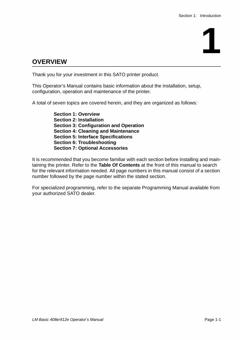
1OVERVIEW
Thank you for your investment in this SATO printer product.
This Operator’s Manual contains basic information about the installation, setup, configuration, operation and maintenance of the printer.
A total of seven topics are covered herein, and they are organized as follows:
Section 1: OverviewSection 2: InstallationSection 3: Configuration and OperationSection 4: Cleaning and MaintenanceSection 5: Interface SpecificationsSection 6: TroubleshootingSection 7: Optional Accessories
It is recommended that you become familiar with each section before installing and main-taining the printer. Refer to the Table Of Contents at the front of this manual to search for the relevant information needed. All page numbers in this manual consist of a section number followed by the page number within the stated section.
For specialized programming, refer to the separate Programming Manual available from your authorized SATO dealer.
Section 1: Introduction
Page 1-2 LM Basic 408e/412e Operator’s Manual
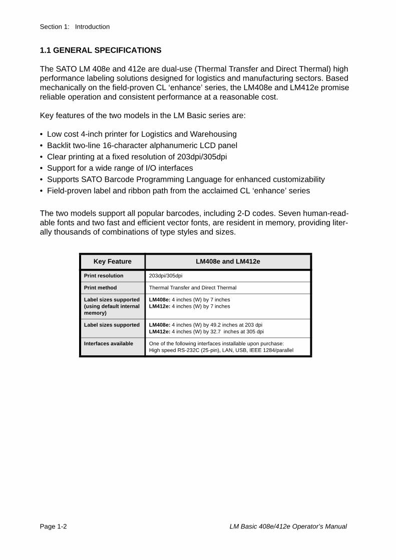
1.1 GENERAL SPECIFICATIONS
The SATO LM 408e and 412e are dual-use (Thermal Transfer and Direct Thermal) high performance labeling solutions designed for logistics and manufacturing sectors. Based mechanically on the field-proven CL ‘enhance’ series, the LM408e and LM412e promise reliable operation and consistent performance at a reasonable cost.
Key features of the two models in the LM Basic series are:
• Low cost 4-inch printer for Logistics and Warehousing• Backlit two-line 16-character alphanumeric LCD panel • Clear printing at a fixed resolution of 203dpi/305dpi• Support for a wide range of I/O interfaces• Supports SATO Barcode Programming Language for enhanced customizability• Field-proven label and ribbon path from the acclaimed CL ‘enhance’ series
The two models support all popular barcodes, including 2-D codes. Seven human-read-able fonts and two fast and efficient vector fonts, are resident in memory, providing liter-ally thousands of combinations of type styles and sizes.
Key Feature LM408e and LM412e
Print resolution 203dpi/305dpi
Print method Thermal Transfer and Direct Thermal
Label sizes supported (using default internal memory)
LM408e: 4 inches (W) by 7 inchesLM412e: 4 inches (W) by 7 inches
Label sizes supported LM408e: 4 inches (W) by 49.2 inches at 203 dpiLM412e: 4 inches (W) by 32.7 inches at 305 dpi
Interfaces available One of the following interfaces installable upon purchase:High speed RS-232C (25-pin), LAN, USB, IEEE 1284/parallel
Section 1: Introduction
LM Basic 408e/412e Operator’s Manual Page 1-3
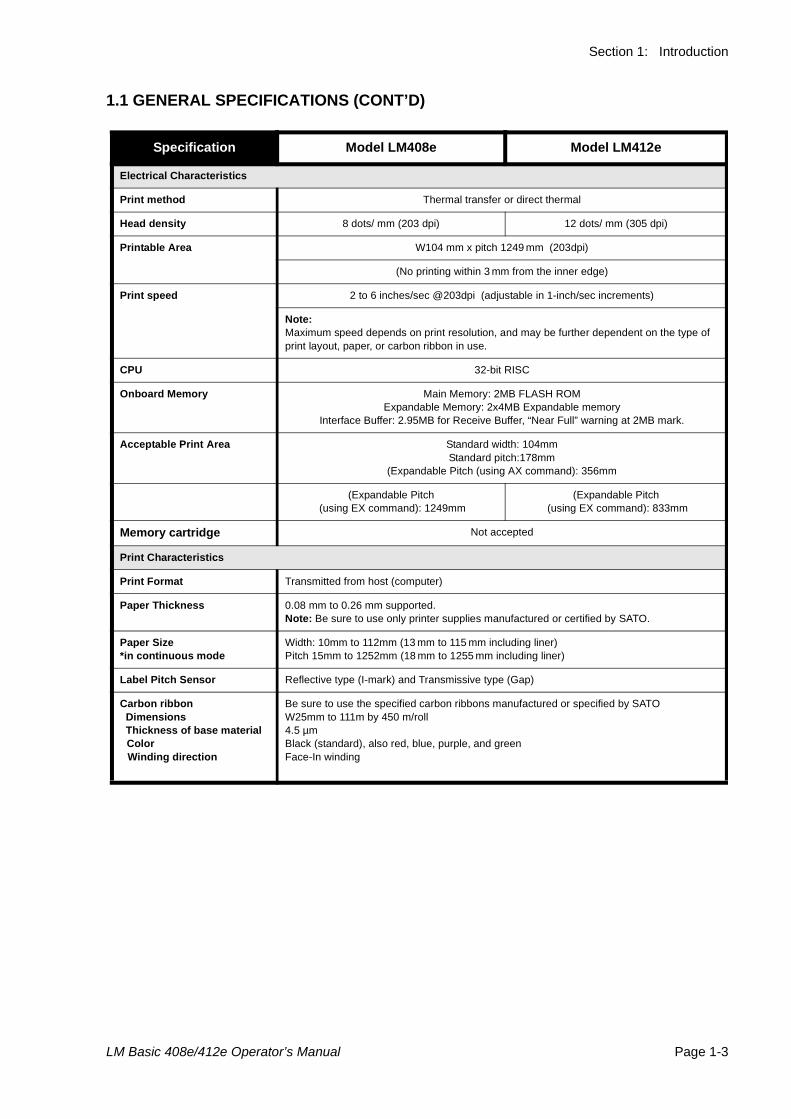
1.1 GENERAL SPECIFICATIONS (CONT’D)
Specification Model LM408e Model LM412e
Electrical Characteristics
Print method Thermal transfer or direct thermal
Head density 8 dots/ mm (203 dpi) 12 dots/ mm (305 dpi)
Printable Area W104 mm x pitch 1249 mm (203dpi)
(No printing within 3 mm from the inner edge)
Print speed 2 to 6 inches/sec @203dpi (adjustable in 1-inch/sec increments)
Note: Maximum speed depends on print resolution, and may be further dependent on the type of print layout, paper, or carbon ribbon in use.
CPU 32-bit RISC
Onboard Memory Main Memory: 2MB FLASH ROM Expandable Memory: 2x4MB Expandable memory
Interface Buffer: 2.95MB for Receive Buffer, “Near Full” warning at 2MB mark.
Acceptable Print Area Standard width: 104mm Standard pitch:178mm
(Expandable Pitch (using AX command): 356mm
(Expandable Pitch (using EX command): 1249mm
(Expandable Pitch (using EX command): 833mm
Memory cartridge Not accepted
Print Characteristics
Print Format Transmitted from host (computer)
Paper Thickness 0.08 mm to 0.26 mm supported. Note: Be sure to use only printer supplies manufactured or certified by SATO.
Paper Size*in continuous mode
Width: 10mm to 112mm (13 mm to 115 mm including liner)Pitch 15mm to 1252mm (18 mm to 1255 mm including liner)
Label Pitch Sensor Reflective type (I-mark) and Transmissive type (Gap)
Carbon ribbon Dimensions Thickness of base material Color Winding direction
Be sure to use the specified carbon ribbons manufactured or specified by SATOW25mm to 111m by 450 m/roll4.5 µmBlack (standard), also red, blue, purple, and greenFace-In winding
Section 1: Introduction
Page 1-4 LM Basic 408e/412e Operator’s Manual
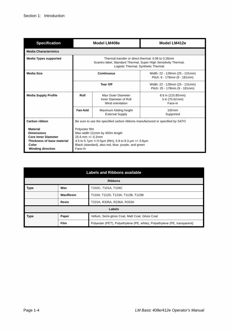
Specification Model LM408e Model LM412e
Media Characteristics
Media Types supported Thermal transfer or direct thermal: 0.08 to 0.26mmScantro label, Standard Thermal, Super HIgh Sensitivity Thermal,
Logistic Thermal, Synthetic Thermal
Media Size Continuous Width: 22 - 128mm (25 - 131mm)Pitch: 6 - 178mm (9 - 181mm)
Tear Off Width: 22 - 128mm (25 - 131mm)Pitch: 20 - 178mm (9 - 181mm)
Media Supply Profile Roll Max Outer DiameterInner Diameter of Roll
Wind orientation
8.6 in (210.85mm)3 in (70.62mm)
Face-in
Fan-fold Maximum folding heightExternal Supply
100mmSupported
Carbon ribbon Material Dimensions Core Inner Diameter Thickness of base material Color Winding direction
Be sure to use the specified carbon ribbons manufactured or specified by SATO
Polyester filmMax width 111mm by 450m length25.6 mm +/- 0.3mm4.5 to 5.7µm +/-0.5µm (film), 5.8 to 8.3 µm +/- 0.6µmBlack (standard), also red, blue, purple, and greenFace-In
Labels and Ribbons available
Ribbons
Type Wax T102C, T101A, T104C
Wax/Resin T110A, T112D, T123A, T112B, T123B
Resin T222A, R335A, R236A, R333A
Labels
Type Paper Vellum, Semi-gloss Coat, Matt Coat, Gloss Coat
Film Polyester (PET), Polyethylene (PE, white), Polyethylene (PE, transparent)
Section 1: Introduction
LM Basic 408e/412e Operator’s Manual Page 1-5
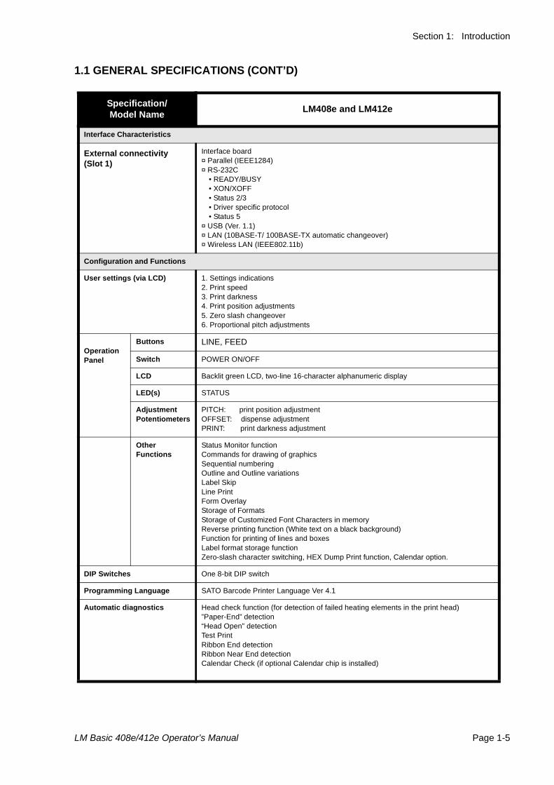
1.1 GENERAL SPECIFICATIONS (CONT’D)
Specification/Model Name LM408e and LM412e
Interface Characteristics
External connectivity (Slot 1)
Interface board¤ Parallel (IEEE1284)¤ RS-232C
• READY/BUSY• XON/XOFF• Status 2/3• Driver specific protocol• Status 5
¤ USB (Ver. 1.1)¤ LAN (10BASE-T/ 100BASE-TX automatic changeover)¤ Wireless LAN (IEEE802.11b)
Configuration and Functions
User settings (via LCD) 1. Settings indications 2. Print speed 3. Print darkness4. Print position adjustments 5. Zero slash changeover 6. Proportional pitch adjustments
Operation Panel
Buttons LINE, FEED
Switch POWER ON/OFF
LCD Backlit green LCD, two-line 16-character alphanumeric display
LED(s) STATUS
AdjustmentPotentiometers
PITCH: print position adjustmentOFFSET: dispense adjustmentPRINT: print darkness adjustment
Other Functions
Status Monitor functionCommands for drawing of graphics Sequential numbering Outline and Outline variationsLabel SkipLine PrintForm OverlayStorage of FormatsStorage of Customized Font Characters in memory Reverse printing function (White text on a black background)Function for printing of lines and boxesLabel format storage functionZero-slash character switching, HEX Dump Print function, Calendar option.
DIP Switches One 8-bit DIP switch
Programming Language SATO Barcode Printer Language Ver 4.1
Automatic diagnostics Head check function (for detection of failed heating elements in the print head)”Paper-End” detection“Head Open” detectionTest Print Ribbon End detection Ribbon Near End detectionCalendar Check (if optional Calendar chip is installed)
Section 1: Introduction
Page 1-6 LM Basic 408e/412e Operator’s Manual
1.1 GENERAL SPECIFICATIONS (CONT’D)
Specification/Model Name LM408e and LM412e
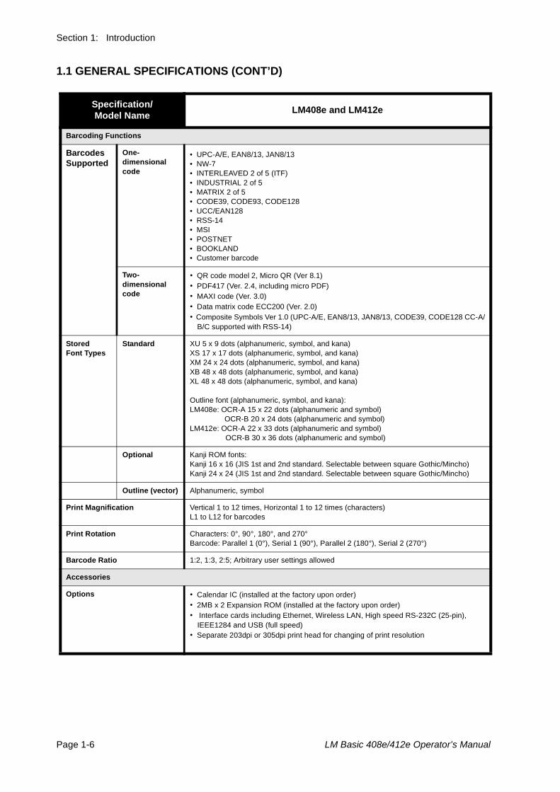
Barcoding Functions
BarcodesSupported
One-dimensional code
• UPC-A/E, EAN8/13, JAN8/13• NW-7• INTERLEAVED 2 of 5 (ITF)• INDUSTRIAL 2 of 5• MATRIX 2 of 5• CODE39, CODE93, CODE128• UCC/EAN128• RSS-14• MSI• POSTNET• BOOKLAND• Customer barcode
Two-dimensional code
• QR code model 2, Micro QR (Ver 8.1)• PDF417 (Ver. 2.4, including micro PDF)• MAXI code (Ver. 3.0)• Data matrix code ECC200 (Ver. 2.0)• Composite Symbols Ver 1.0 (UPC-A/E, EAN8/13, JAN8/13, CODE39, CODE128 CC-A/
B/C supported with RSS-14)
Stored Font Types
Standard XU 5 x 9 dots (alphanumeric, symbol, and kana)XS 17 x 17 dots (alphanumeric, symbol, and kana)XM 24 x 24 dots (alphanumeric, symbol, and kana)XB 48 x 48 dots (alphanumeric, symbol, and kana)XL 48 x 48 dots (alphanumeric, symbol, and kana)
Outline font (alphanumeric, symbol, and kana):LM408e: OCR-A 15 x 22 dots (alphanumeric and symbol) OCR-B 20 x 24 dots (alphanumeric and symbol)LM412e: OCR-A 22 x 33 dots (alphanumeric and symbol) OCR-B 30 x 36 dots (alphanumeric and symbol)
Optional Kanji ROM fonts:Kanji 16 x 16 (JIS 1st and 2nd standard. Selectable between square Gothic/Mincho)Kanji 24 x 24 (JIS 1st and 2nd standard. Selectable between square Gothic/Mincho)
Outline (vector) Alphanumeric, symbol
Print Magnification Vertical 1 to 12 times, Horizontal 1 to 12 times (characters) L1 to L12 for barcodes
Print Rotation Characters: 0°, 90°, 180°, and 270°Barcode: Parallel 1 (0°), Serial 1 (90°), Parallel 2 (180°), Serial 2 (270°)
Barcode Ratio 1:2, 1:3, 2:5; Arbitrary user settings allowed
Accessories
Options • Calendar IC (installed at the factory upon order)• 2MB x 2 Expansion ROM (installed at the factory upon order)• Interface cards including Ethernet, Wireless LAN, High speed RS-232C (25-pin),
IEEE1284 and USB (full speed)• Separate 203dpi or 305dpi print head for changing of print resolution
Section 1: Introduction
LM Basic 408e/412e Operator’s Manual Page 1-7
Specification/Model Name LM408e and LM412e
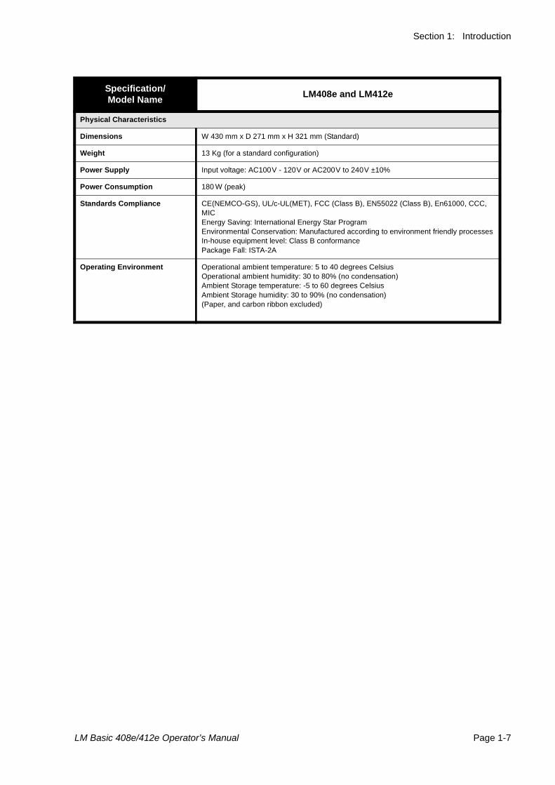
Physical Characteristics
Dimensions W 430 mm x D 271 mm x H 321 mm (Standard)
Weight 13 Kg (for a standard configuration)
Power Supply Input voltage: AC100V - 120V or AC200V to 240V ±10%
Power Consumption 180 W (peak)
Standards Compliance CE(NEMCO-GS), UL/c-UL(MET), FCC (Class B), EN55022 (Class B), En61000, CCC, MICEnergy Saving: International Energy Star ProgramEnvironmental Conservation: Manufactured according to environment friendly processesIn-house equipment level: Class B conformancePackage Fall: ISTA-2A
Operating Environment Operational ambient temperature: 5 to 40 degrees CelsiusOperational ambient humidity: 30 to 80% (no condensation)Ambient Storage temperature: -5 to 60 degrees CelsiusAmbient Storage humidity: 30 to 90% (no condensation)(Paper, and carbon ribbon excluded)

Section 1: Introduction
Page 1-8 LM Basic 408e/412e Operator’s Manual
This page is intentionally left blank
Section 2: Installation
LM Basic 408e/412e Operator’s Manual Page 2-1
2INSTALLATION
This section assists you in unpacking and installing the printer from the shipping container. You will also be guided through a familiarization tour of the main parts and controls. The following information is provided:
• Safety Precautions
• Unpacking and Parts Identification
• Loading the Carbon Ribbon
• Loading Labels and Tags
• Adjusting the Sensors
• Replacing the Print Head
SECTION 2: INSTALLATION
Page 2-2 LM Basic 408e/412e Operator’s Manual
SAFETY PRECAUTIONS
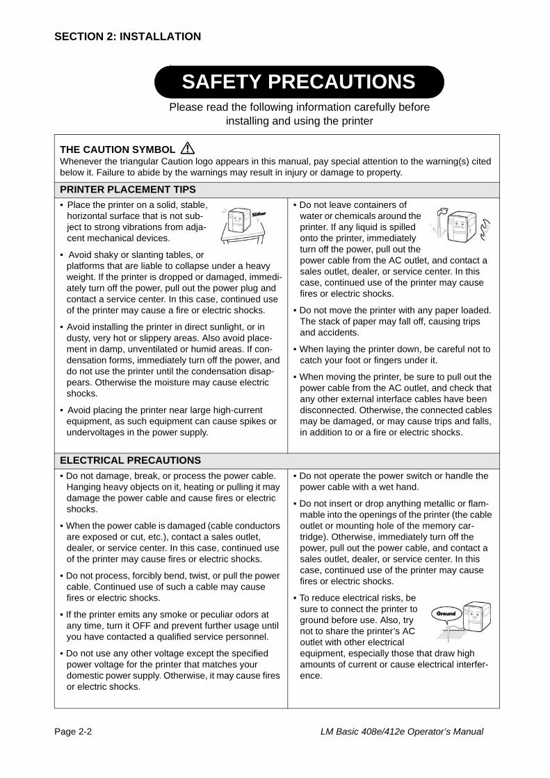
THE CAUTION SYMBOLWhenever the triangular Caution logo appears in this manual, pay special attention to the warning(s) cited below it. Failure to abide by the warnings may result in injury or damage to property.
PRINTER PLACEMENT TIPS• Place the printer on a solid, stable,
horizontal surface that is not sub-ject to strong vibrations from adja-cent mechanical devices.
• Avoid shaky or slanting tables, or platforms that are liable to collapse under a heavy weight. If the printer is dropped or damaged, immedi-ately turn off the power, pull out the power plug and contact a service center. In this case, continued use of the printer may cause a fire or electric shocks.
• Avoid installing the printer in direct sunlight, or in dusty, very hot or slippery areas. Also avoid place-ment in damp, unventilated or humid areas. If con-densation forms, immediately turn off the power, and do not use the printer until the condensation disap-pears. Otherwise the moisture may cause electric shocks.
• Avoid placing the printer near large high-current equipment, as such equipment can cause spikes or undervoltages in the power supply.
• Do not leave containers of water or chemicals around the printer. If any liquid is spilled onto the printer, immediately turn off the power, pull out the power cable from the AC outlet, and contact a sales outlet, dealer, or service center. In this case, continued use of the printer may cause fires or electric shocks.
• Do not move the printer with any paper loaded. The stack of paper may fall off, causing trips and accidents.
• When laying the printer down, be careful not to catch your foot or fingers under it.
• When moving the printer, be sure to pull out the power cable from the AC outlet, and check that any other external interface cables have been disconnected. Otherwise, the connected cables may be damaged, or may cause trips and falls, in addition to or a fire or electric shocks.
ELECTRICAL PRECAUTIONS• Do not damage, break, or process the power cable.
Hanging heavy objects on it, heating or pulling it may damage the power cable and cause fires or electric shocks.
• When the power cable is damaged (cable conductors are exposed or cut, etc.), contact a sales outlet, dealer, or service center. In this case, continued use of the printer may cause fires or electric shocks.
• Do not process, forcibly bend, twist, or pull the power cable. Continued use of such a cable may cause fires or electric shocks.
• If the printer emits any smoke or peculiar odors at any time, turn it OFF and prevent further usage until you have contacted a qualified service personnel.
• Do not use any other voltage except the specified power voltage for the printer that matches your domestic power supply. Otherwise, it may cause fires or electric shocks.
• Do not operate the power switch or handle the power cable with a wet hand.
• Do not insert or drop anything metallic or flam-mable into the openings of the printer (the cable outlet or mounting hole of the memory car-tridge). Otherwise, immediately turn off the power, pull out the power cable, and contact a sales outlet, dealer, or service center. In this case, continued use of the printer may cause fires or electric shocks.
• To reduce electrical risks, be sure to connect the printer to ground before use. Also, try not to share the printer’s AC outlet with other electrical equipment, especially those that draw high amounts of current or cause electrical interfer-ence.
SAFETY PRECAUTIONSPlease read the following information carefully before
installing and using the printer
Section 2: Installation
LM Basic 408e/412e Operator’s Manual Page 2-3
This equipment is a piece of Class B information technology equipment based on the standards of the Voluntary Control Council for Interference by Information Technology Equipment (VCCI). Although this equipment is for use in home environment, if it is used close to a radio or television set, it may cause poor reception. Handle it properly in accordance with the content from the instruction manual.
GENERAL PRECAUTIONS• Head cleaning liquid (if supplied) is flammable. Never
heat it or throw it into a fire. Keep it out of children’s reach to avoid accidental consumption. Should this occur, consult a doctor immediately.
• When opening/closing the cover, beware of getting your fingers caught. Also, hold the opening/closing cover well so that it will not slip and fall on your hand.
• After printing, the print head remains hot. When replacing paper or cleaning the printer immediately after printing, be careful not to burn yourself.
• Touching even the edge of the printer head may cause injuries. When replacing paper or cleaning the printer, be careful not to hurt yourself.
• If the printer will not be used for extended periods of time, disconnect the power cable for safety.
• When releasing and locking down the printer head, be careful not to catch any other foreign matter in it except label paper.
• Do not disassemble or perform modifications to the printer, as this renders the product unsafe. For maintenance, troubleshooting and repairs, consult a sales outlet, dealer, or service center for help, instead of attempting to perform this yourself. Renewable annual service contracts are available.
• When maintaining or cleaning the printer, always disconnect the power cable for safety.
• Do not insert your hand or other objects into the cutter.
• When loading roll paper, be careful not to catch your fingers between the paper and the feeder.
• Be careful not to hurt yourself when detaching the back cover of the fanfold through the hole and attaching it.
• The simplified cutter (where installed) is struc-tured as a blade. Be careful not to cut yourself.
SECTION 2: INSTALLATION
Page 2-4 LM Basic 408e/412e Operator’s Manual
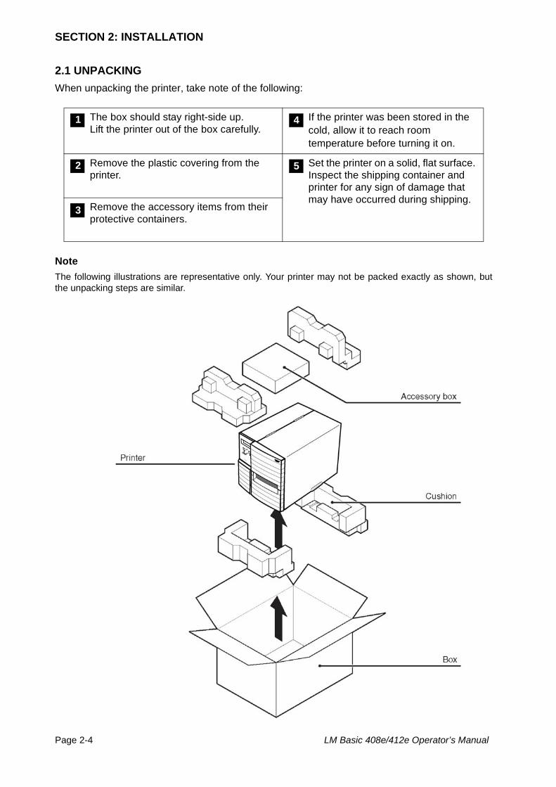
2.1 UNPACKINGWhen unpacking the printer, take note of the following:
Note The following illustrations are representative only. Your printer may not be packed exactly as shown, butthe unpacking steps are similar.
The box should stay right-side up.Lift the printer out of the box carefully.
If the printer was been stored in the cold, allow it to reach room temperature before turning it on.
Remove the plastic covering from the printer.
Set the printer on a solid, flat surface. Inspect the shipping container and printer for any sign of damage that may have occurred during shipping.
Remove the accessory items from their protective containers.
1 4
2 5
3
Section 2: Installation
LM Basic 408e/412e Operator’s Manual Page 2-5
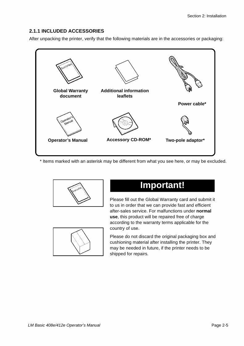
2.1.1 INCLUDED ACCESSORIES After unpacking the printer, verify that the following materials are in the accessories or packaging:
Global Warranty document
Additional information leaflets
Power cable*
Two-pole adaptor*Accessory CD-ROM*Operator’s Manual
* Items marked with an asterisk may be different from what you see here, or may be excluded.
Please fill out the Global Warranty card and submit it to us in order that we can provide fast and efficient after-sales service. For malfunctions under normal use, this product will be repaired free of charge according to the warranty terms applicable for the country of use.
Please do not discard the original packaging box and cushioning material after installing the printer. They may be needed in future, if the printer needs to be shipped for repairs.
Important!
SECTION 2: INSTALLATION
Page 2-6 LM Basic 408e/412e Operator’s Manual
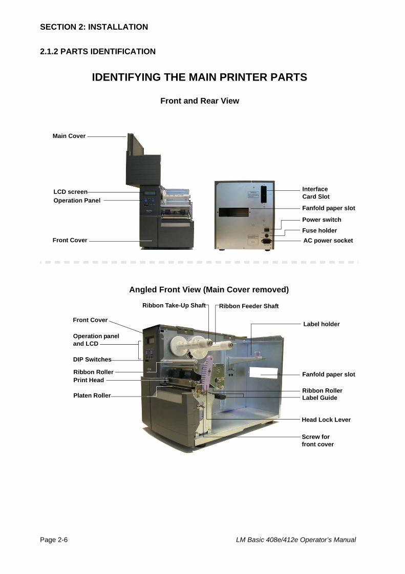
2.1.2 PARTS IDENTIFICATION
IDENTIFYING THE MAIN PRINTER PARTS
Power switch
Operation Panel
Front Cover
Operation panel and LCD
Platen Roller
Label holder
Angled Front View (Main Cover removed)
Front and Rear View
Head Lock Lever
DIP Switches
Interface Card Slot
AC power socketFuse holder
Fanfold paper slot
Main Cover
LCD screen
Front Cover
Fanfold paper slot
Ribbon Feeder ShaftRibbon Take-Up Shaft
Label Guide
Ribbon Roller
Ribbon RollerPrint Head
Screw for front cover
Section 2: Installation
LM Basic 408e/412e Operator’s Manual Page 2-7
2.1.2 PARTS IDENTIFICATION (CONT’D)
IDENTIFYING THE MAIN PRINTER PARTS
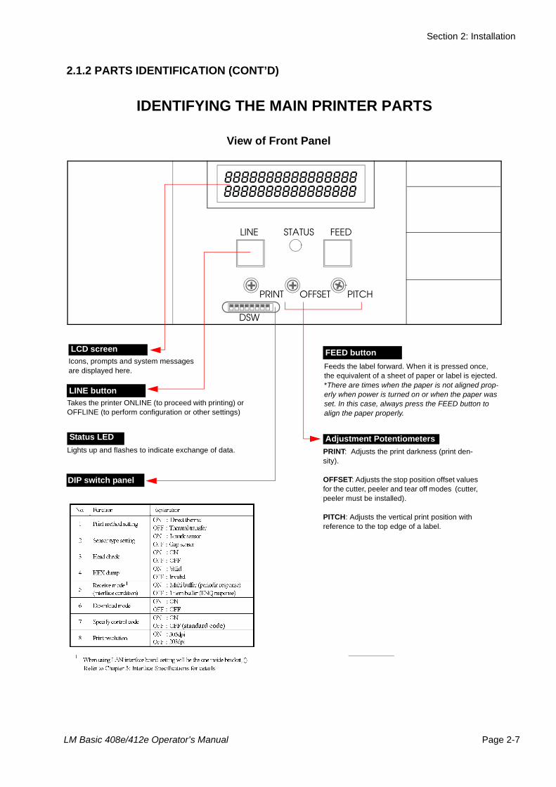
View of Front Panel
Icons, prompts and system messages are displayed here.
LCD screen
. Feeds the label forward. When it is pressed once,the equivalent of a sheet of paper or label is ejected. *There are times when the paper is not aligned prop-erly when power is turned on or when the paper was set. In this case, always press the FEED button to align the paper properly.
FEED button
Status LEDLights up and flashes to indicate exchange of data.
Adjustment PotentiometersPRINT: Adjusts the print darkness (print den-sity).
OFFSET: Adjusts the stop position offset values for the cutter, peeler and tear off modes (cutter, peeler must be installed).
PITCH: Adjusts the vertical print position with reference to the top edge of a label.
LINE STATUS FEED
PRINT OFFSET PITCH
DSW
88888888888888888888888888888888
LINE buttonTakes the printer ONLINE (to proceed with printing) or OFFLINE (to perform configuration or other settings)
DIP switch panel
SECTION 2: INSTALLATION
Page 2-8 LM Basic 408e/412e Operator’s Manual
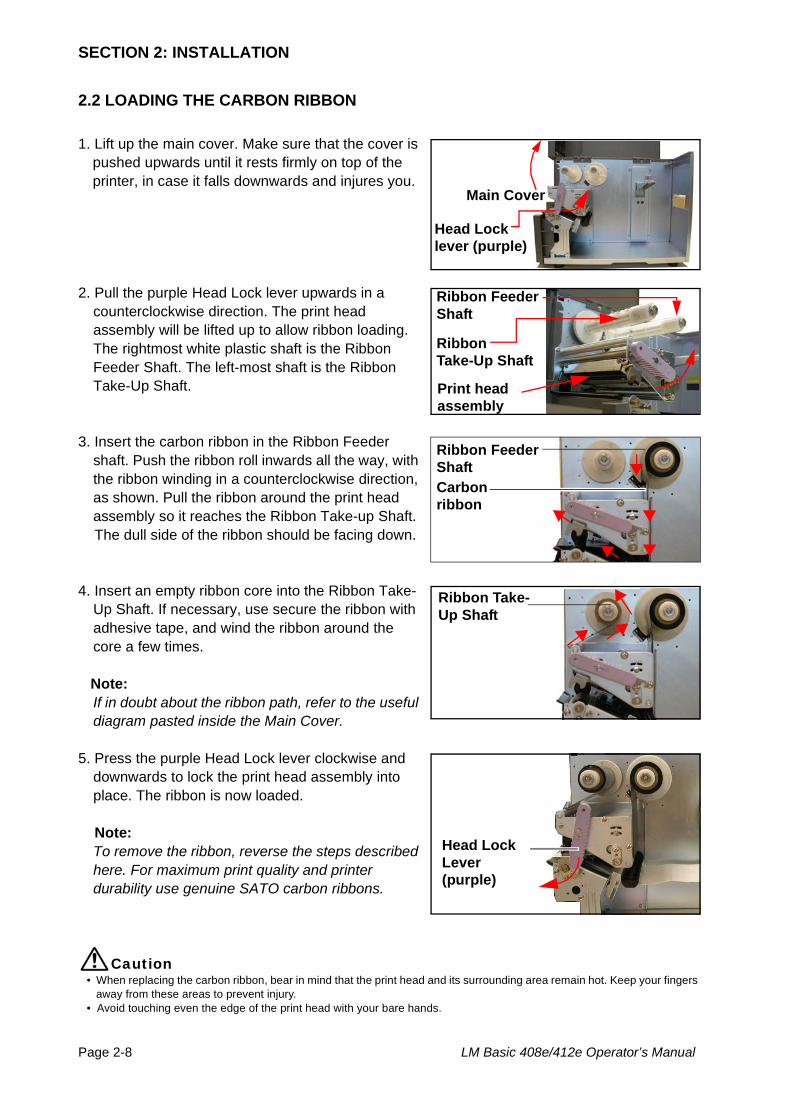
2.2 LOADING THE CARBON RIBBON
1. Lift up the main cover. Make sure that the cover is pushed upwards until it rests firmly on top of the printer, in case it falls downwards and injures you.
2. Pull the purple Head Lock lever upwards in a counterclockwise direction. The print head assembly will be lifted up to allow ribbon loading.The rightmost white plastic shaft is the Ribbon Feeder Shaft. The left-most shaft is the Ribbon Take-Up Shaft.
3. Insert the carbon ribbon in the Ribbon Feeder shaft. Push the ribbon roll inwards all the way, with the ribbon winding in a counterclockwise direction, as shown. Pull the ribbon around the print head assembly so it reaches the Ribbon Take-up Shaft.
The dull side of the ribbon should be facing down.
4. Insert an empty ribbon core into the Ribbon Take-Up Shaft. If necessary, use secure the ribbon with adhesive tape, and wind the ribbon around the core a few times.
Note:If in doubt about the ribbon path, refer to the useful diagram pasted inside the Main Cover.
5. Press the purple Head Lock lever clockwise and downwards to lock the print head assembly into place. The ribbon is now loaded.
Note:To remove the ribbon, reverse the steps described here. For maximum print quality and printer durability use genuine SATO carbon ribbons.
Caution• When replacing the carbon ribbon, bear in mind that the print head and its surrounding area remain hot. Keep your fingers away from these areas to prevent injury. • Avoid touching even the edge of the print head with your bare hands.
Main Cover
Head Locklever (purple)
Print head assembly
Ribbon Feeder Shaft
Ribbon Take-Up Shaft
Ribbon Feeder ShaftCarbon ribbon
Ribbon Take-Up Shaft
Head Lock Lever (purple)
Section 2: Installation
LM Basic 408e/412e Operator’s Manual Page 2-9
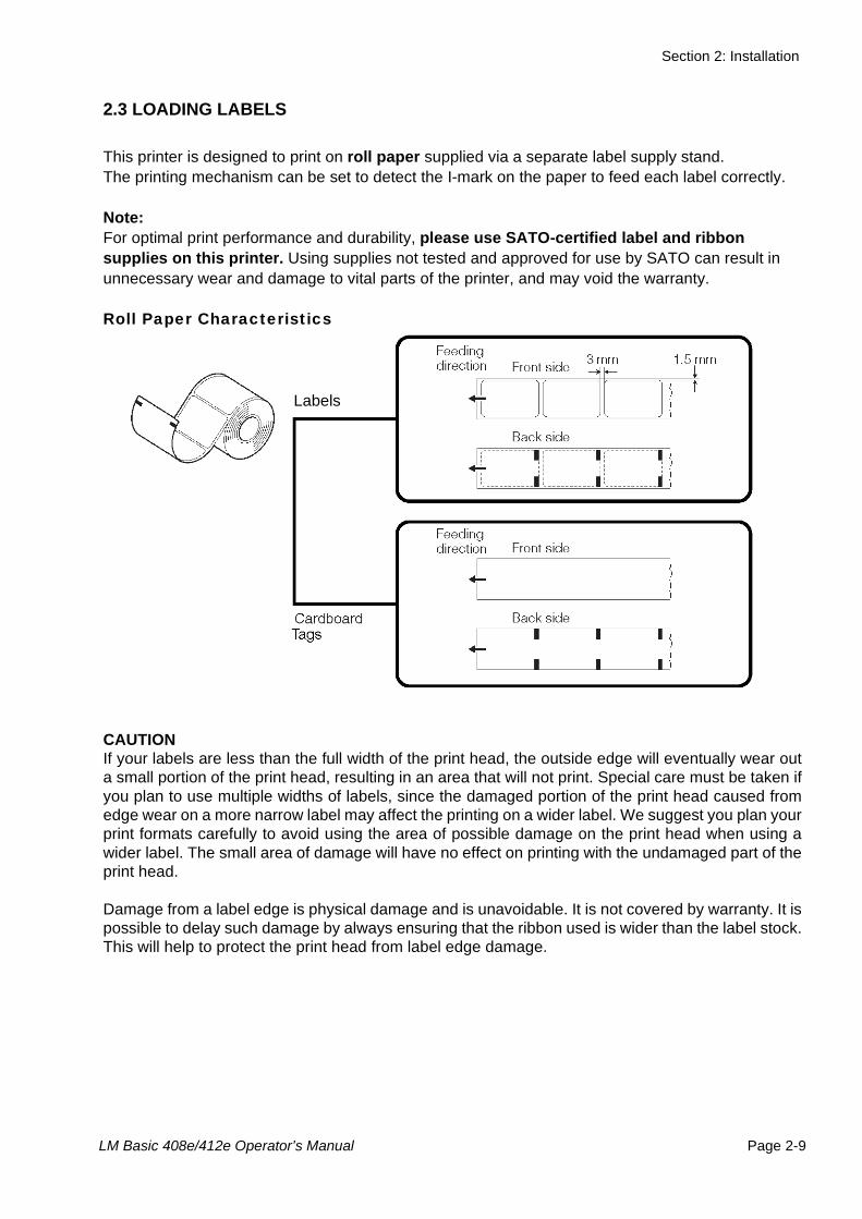
2.3 LOADING LABELS
This printer is designed to print on roll paper supplied via a separate label supply stand.The printing mechanism can be set to detect the I-mark on the paper to feed each label correctly.
Note:For optimal print performance and durability, please use SATO-certified label and ribbon supplies on this printer. Using supplies not tested and approved for use by SATO can result in unnecessary wear and damage to vital parts of the printer, and may void the warranty.
Roll Paper Characteristics
CAUTIONIf your labels are less than the full width of the print head, the outside edge will eventually wear outa small portion of the print head, resulting in an area that will not print. Special care must be taken ifyou plan to use multiple widths of labels, since the damaged portion of the print head caused fromedge wear on a more narrow label may affect the printing on a wider label. We suggest you plan yourprint formats carefully to avoid using the area of possible damage on the print head when using awider label. The small area of damage will have no effect on printing with the undamaged part of theprint head.
Damage from a label edge is physical damage and is unavoidable. It is not covered by warranty. It ispossible to delay such damage by always ensuring that the ribbon used is wider than the label stock.This will help to protect the print head from label edge damage.
Labels
SECTION 2: INSTALLATION
Page 2-10 LM Basic 408e/412e Operator’s Manual
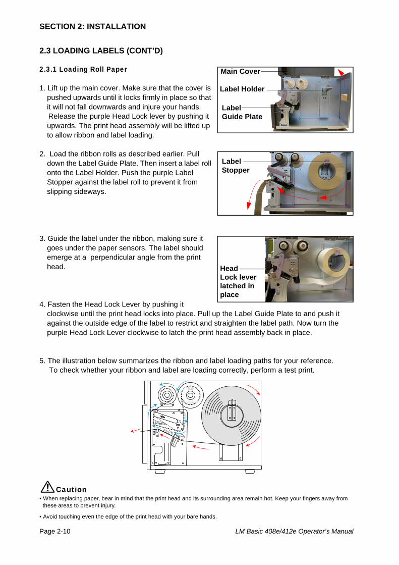
2.3 LOADING LABELS (CONT’D)
2.3.1 Loading Roll Paper
1. Lift up the main cover. Make sure that the cover is pushed upwards until it locks firmly in place so that it will not fall downwards and injure your hands.
Release the purple Head Lock lever by pushing it upwards. The print head assembly will be lifted up to allow ribbon and label loading.
2. Load the ribbon rolls as described earlier. Pull down the Label Guide Plate. Then insert a label roll onto the Label Holder. Push the purple Label Stopper against the label roll to prevent it from slipping sideways.
3. Guide the label under the ribbon, making sure it goes under the paper sensors. The label should emerge at a perpendicular angle from the print head.
4. Fasten the Head Lock Lever by pushing it clockwise until the print head locks into place. Pull up the Label Guide Plate to and push it against the outside edge of the label to restrict and straighten the label path. Now turn the purple Head Lock Lever clockwise to latch the print head assembly back in place.
5. The illustration below summarizes the ribbon and label loading paths for your reference. To check whether your ribbon and label are loading correctly, perform a test print.
Caution• When replacing paper, bear in mind that the print head and its surrounding area remain hot. Keep your fingers away from
these areas to prevent injury.
• Avoid touching even the edge of the print head with your bare hands.
Main Cover
Label Holder
Label Guide Plate
Label Stopper
Head Lock lever latched in place
Section 2: Installation
LM Basic 408e/412e Operator’s Manual Page 2-11
2.3 LOADING LABELS (CONT’D)
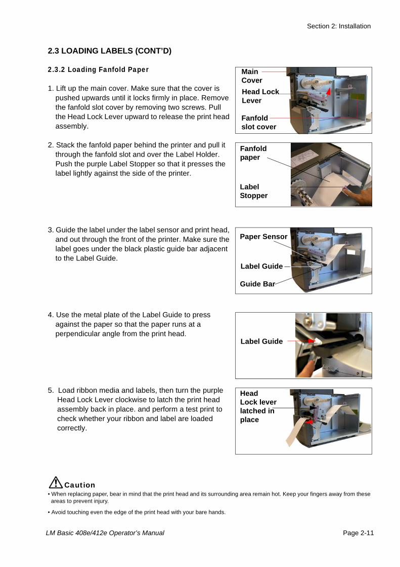
2.3.2 Loading Fanfold Paper
1. Lift up the main cover. Make sure that the cover is pushed upwards until it locks firmly in place. Remove the fanfold slot cover by removing two screws. Pull the Head Lock Lever upward to release the print head assembly.
2. Stack the fanfold paper behind the printer and pull it through the fanfold slot and over the Label Holder. Push the purple Label Stopper so that it presses the label lightly against the side of the printer.
3. Guide the label under the label sensor and print head, and out through the front of the printer. Make sure the label goes under the black plastic guide bar adjacent to the Label Guide.
4. Use the metal plate of the Label Guide to press against the paper so that the paper runs at a perpendicular angle from the print head.
5. Load ribbon media and labels, then turn the purple Head Lock Lever clockwise to latch the print head assembly back in place. and perform a test print to check whether your ribbon and label are loaded correctly.
Caution• When replacing paper, bear in mind that the print head and its surrounding area remain hot. Keep your fingers away from these
areas to prevent injury.
• Avoid touching even the edge of the print head with your bare hands.
Main Cover
Fanfoldslot cover
Head Lock Lever
Fanfold paper
LabelStopper
Label Guide
Paper Sensor
Guide Bar
Label Guide
Head Lock lever latched in place
SECTION 2: INSTALLATION
Page 2-12 LM Basic 408e/412e Operator’s Manual
2.3 LOADING LABELS AND TAGS (CONT’D)
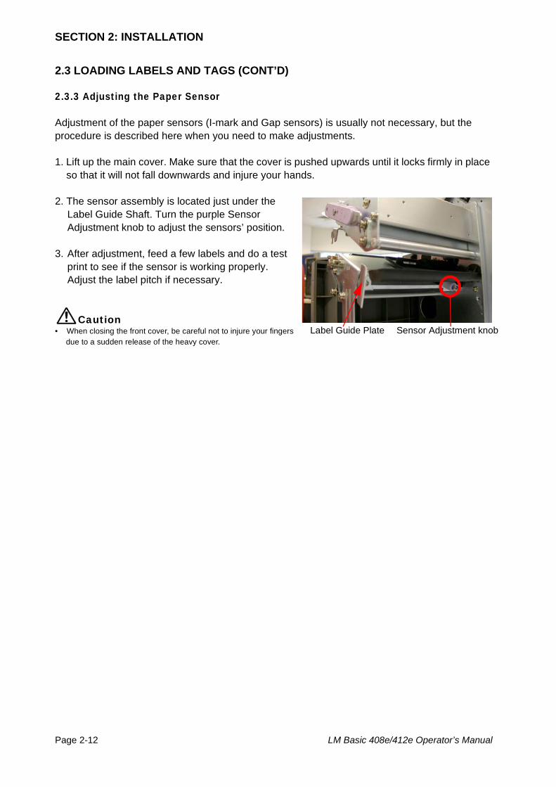
2.3.3 Adjusting the Paper Sensor
Adjustment of the paper sensors (I-mark and Gap sensors) is usually not necessary, but the procedure is described here when you need to make adjustments.
1. Lift up the main cover. Make sure that the cover is pushed upwards until it locks firmly in place so that it will not fall downwards and injure your hands.
2. The sensor assembly is located just under the Label Guide Shaft. Turn the purple Sensor Adjustment knob to adjust the sensors’ position.
3. After adjustment, feed a few labels and do a test print to see if the sensor is working properly. Adjust the label pitch if necessary.
Caution• When closing the front cover, be careful not to injure your fingers
due to a sudden release of the heavy cover.Sensor Adjustment knobLabel Guide Plate
Section 2: Installation
LM Basic 408e/412e Operator’s Manual Page 2-13
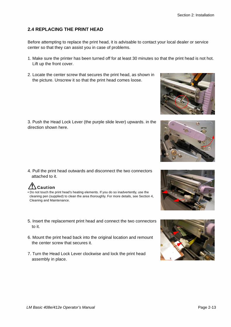
2.4 REPLACING THE PRINT HEAD
Before attempting to replace the print head, it is advisable to contact your local dealer or service center so that they can assist you in case of problems.
1. Make sure the printer has been turned off for at least 30 minutes so that the print head is not hot. Lift up the front cover.
2. Locate the center screw that secures the print head, as shown in the picture. Unscrew it so that the print head comes loose.
3. Push the Head Lock Lever (the purple slide lever) upwards. in the direction shown here.
4. Pull the print head outwards and disconnect the two connectors attached to it.
Caution• Do not touch the print head’s heating elements. If you do so inadvertently, use the
cleaning pen (supplied) to clean the area thoroughly. For more details, see Section 4, Cleaning and Maintenance.
5. Insert the replacement print head and connect the two connectors to it.
6. Mount the print head back into the original location and remount the center screw that secures it.
7. Turn the Head Lock Lever clockwise and lock the print head assembly in place.
C

SECTION 2: INSTALLATION
Page 2-14 LM Basic 408e/412e Operator’s Manual
This page is intentionally left blank
Section 3: Configuration and Operation
LM Basic 408e/412e Operator’s Manual Page 3-1
3CONFIGURATION AND OPERATION
Before using the printer, it is best to read this manual thoroughly first. Otherwise, you may disturb default settings around which the instructional procedures in this manual are based on.
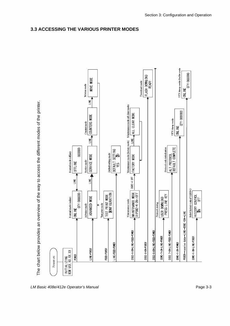
3.1 OPERATING MODESThe operating status of this printer can be set to one of nine modes:
1) Normal (Online and Offline) Modes2) Advanced Mode3) Service Mode4) Counters Mode5) Move Mode6) Test Print Mode7) Maintenance (Factory/All Clear) Mode8) Boot Download Mode9) Hex Dump Mode
The different modes are accessed through a combination of setting DIP switches and holding down certain buttons on the Operation Panel when you turn the printer ON. These are explained in the following sections.
NoteDue to SATO’s continual efforts to improve the printer firmware and hardware, the sequence and availability of LCD menus described here may not be similar to what is available on your version of LM Basic. In this case, visit SATO’s website at http://www.satoworldwide.com for supplementary and updated documentation.
Section 3: Configuration and Operation
Page 3-2 LM Basic 408e/412e Operator’s Manual
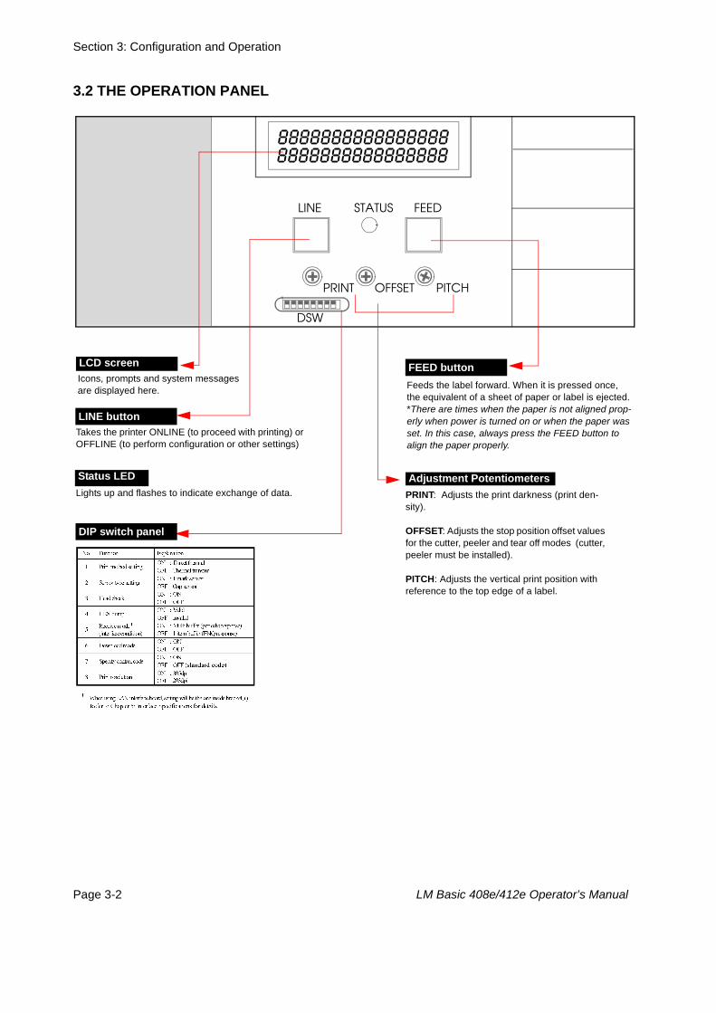
3.2 THE OPERATION PANEL
LINE STATUS FEED
PRINT OFFSET PITCH
DSW
88888888888888888888888888888888
Icons, prompts and system messages are displayed here.
LCD screen
Feeds the label forward. When it is pressed once,the equivalent of a sheet of paper or label is ejected. *There are times when the paper is not aligned prop-erly when power is turned on or when the paper was set. In this case, always press the FEED button to align the paper properly.
FEED button
Status LEDLights up and flashes to indicate exchange of data.
Adjustment PotentiometersPRINT: Adjusts the print darkness (print den-sity).
OFFSET: Adjusts the stop position offset values for the cutter, peeler and tear off modes (cutter, peeler must be installed).
PITCH: Adjusts the vertical print position with reference to the top edge of a label.
LINE buttonTakes the printer ONLINE (to proceed with printing) or OFFLINE (to perform configuration or other settings)
DIP switch panel
Section 3: Configuration and Operation
LM Basic 408e/412e Operator’s Manual Page 3-3
3.3 ACCESSING THE VARIOUS PRINTER MODES
The
char
t bel
ow p
rovi
des
an o
verv
iew
of t
he w
ay to
acc
ess
the
diffe
rent
mod
es o
f the
prin
ter.
Section 3: Configuration and Operation
Page 3-4 LM Basic 408e/412e Operator’s Manual
3.3 ACCESSING THE VARIOUS PRINTER MODES (CONT’D)
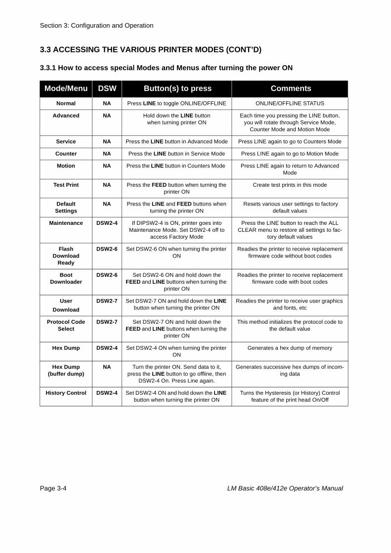
3.3.1 How to access special Modes and Menus after turning the power ON
Mode/Menu DSW Button(s) to press Comments
Normal NA Press LINE to toggle ONLINE/OFFLINE ONLINE/OFFLINE STATUS
Advanced NA Hold down the LINE button when turning printer ON
Each time you pressing the LINE button, you will rotate through Service Mode,
Counter Mode and Motion Mode
Service NA Press the LINE button in Advanced Mode Press LINE again to go to Counters Mode
Counter NA Press the LINE button in Service Mode Press LINE again to go to Motion Mode
Motion NA Press the LINE button in Counters Mode Press LINE again to return to Advanced Mode
Test Print NA Press the FEED button when turning the printer ON
Create test prints in this mode
Default Settings
NA Press the LINE and FEED buttons when turning the printer ON
Resets various user settings to factory default values
Maintenance DSW2-4 If DIPSW2-4 is ON, printer goes into Maintenance Mode. Set DSW2-4 off to
access Factory Mode
Press the LINE button to reach the ALL CLEAR menu to restore all settings to fac-
tory default values
Flash Download
Ready
DSW2-6 Set DSW2-6 ON when turning the printer ON
Readies the printer to receive replacement firmware code without boot codes
Boot Downloader
DSW2-6 Set DSW2-6 ON and hold down the FEED and LINE buttons when turning the
printer ON
Readies the printer to receive replacement firmware code with boot codes
User Download
DSW2-7 Set DSW2-7 ON and hold down the LINE button when turning the printer ON
Readies the printer to receive user graphics and fonts, etc
Protocol Code Select
DSW2-7 Set DSW2-7 ON and hold down the FEED and LINE buttons when turning the
printer ON
This method initializes the protocol code to the default value
Hex Dump DSW2-4 Set DSW2-4 ON when turning the printer ON
Generates a hex dump of memory
Hex Dump (buffer dump)
NA Turn the printer ON. Send data to it, press the LINE button to go offline, then
DSW2-4 On. Press Line again.
Generates successive hex dumps of incom-ing data
History Control DSW2-4 Set DSW2-4 ON and hold down the LINE button when turning the printer ON
Turns the Hysteresis (or History) Control feature of the print head On/Off
Section 3: Configuration and Operation
LM Basic 408e/412e Operator’s Manual Page 3-5
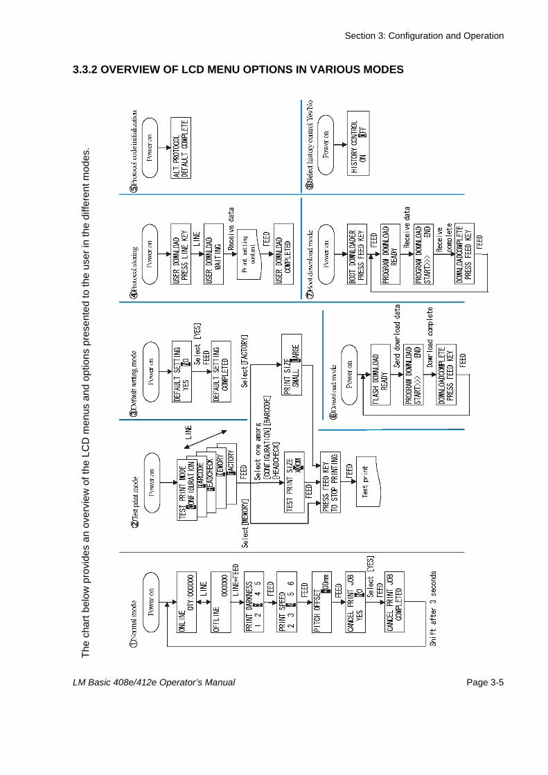
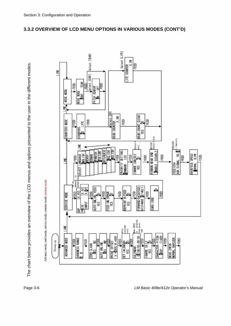
3.3.2 OVERVIEW OF LCD MENU OPTIONS IN VARIOUS MODESTh
e ch
art b
elow
pro
vide
s an
ove
rvie
w o
f the
LC
D m
enus
and
opt
ions
pre
sent
ed to
the
user
in th
e di
ffere
nt m
odes
.
Section 3: Configuration and Operation
Page 3-6 LM Basic 408e/412e Operator’s Manual
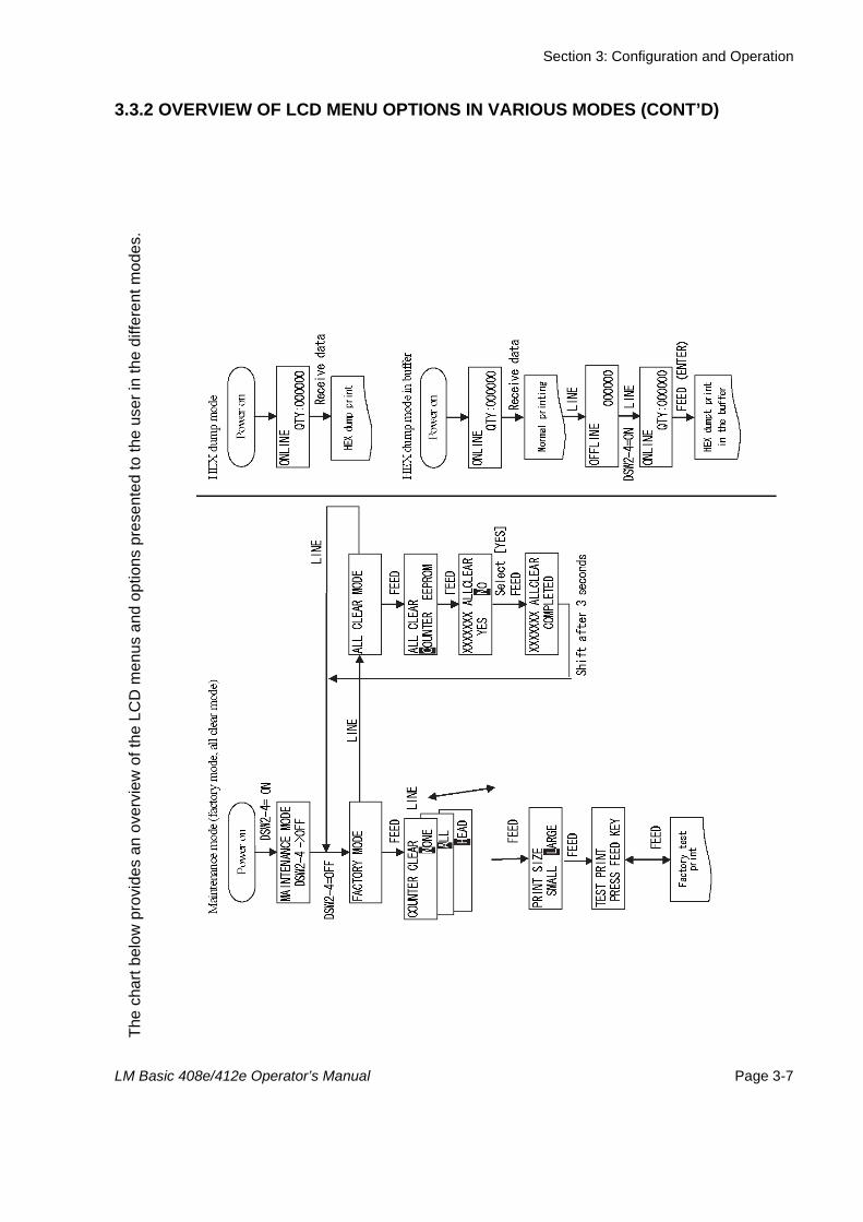
3.3.2 OVERVIEW OF LCD MENU OPTIONS IN VARIOUS MODES (CONT’D)Th
e ch
art b
elow
pro
vide
s an
ove
rvie
w o
f the
LC
D m
enus
and
opt
ions
pre
sent
ed to
the
user
in th
e di
ffere
nt m
odes
.
Section 3: Configuration and Operation
LM Basic 408e/412e Operator’s Manual Page 3-7
3.3.2 OVERVIEW OF LCD MENU OPTIONS IN VARIOUS MODES (CONT’D)Th
e ch
art b
elow
pro
vide
s an
ove
rvie
w o
f the
LC
D m
enus
and
opt
ions
pre
sent
ed to
the
user
in th
e di
ffere
nt m
odes
.
Section 3: Configuration and Operation
Page 3-8 LM Basic 408e/412e Operator’s Manual
3.4 NORMAL MODES
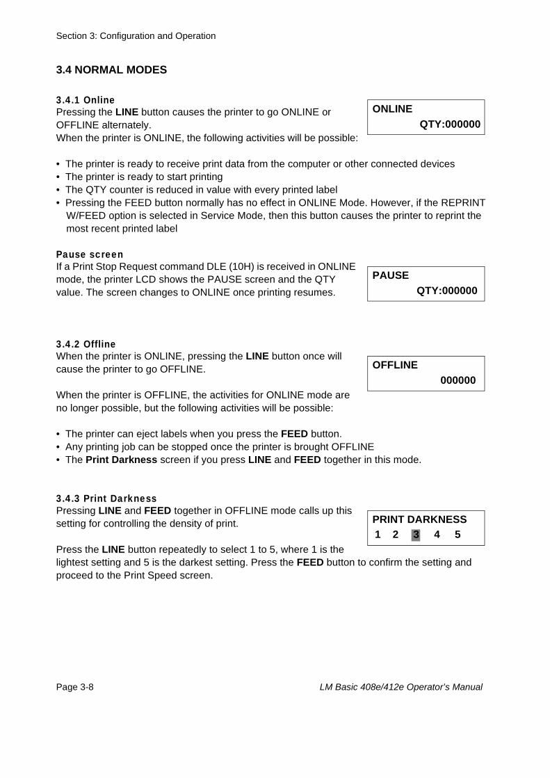
3.4.1 Online Pressing the LINE button causes the printer to go ONLINE or OFFLINE alternately.When the printer is ONLINE, the following activities will be possible:
• The printer is ready to receive print data from the computer or other connected devices• The printer is ready to start printing• The QTY counter is reduced in value with every printed label• Pressing the FEED button normally has no effect in ONLINE Mode. However, if the REPRINT
W/FEED option is selected in Service Mode, then this button causes the printer to reprint the most recent printed label
Pause screenIf a Print Stop Request command DLE (10H) is received in ONLINE mode, the printer LCD shows the PAUSE screen and the QTY value. The screen changes to ONLINE once printing resumes.
3.4.2 OfflineWhen the printer is ONLINE, pressing the LINE button once will cause the printer to go OFFLINE.
When the printer is OFFLINE, the activities for ONLINE mode are no longer possible, but the following activities will be possible:
• The printer can eject labels when you press the FEED button.• Any printing job can be stopped once the printer is brought OFFLINE• The Print Darkness screen if you press LINE and FEED together in this mode.
3.4.3 Print DarknessPressing LINE and FEED together in OFFLINE mode calls up this setting for controlling the density of print.
Press the LINE button repeatedly to select 1 to 5, where 1 is the lightest setting and 5 is the darkest setting. Press the FEED button to confirm the setting and proceed to the Print Speed screen.
ONLINE QTY:000000
PAUSE QTY:000000
OFFLINE 000000
PRINT DARKNESS 1 2 3 4 5
Section 3: Configuration and Operation
LM Basic 408e/412e Operator’s Manual Page 3-9
3.4 NORMAL MODES (CONT’D)
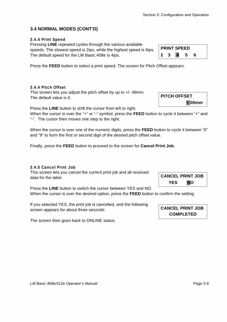
3.4.4 Print SpeedPressing LINE repeated cycles through the various available speeds. The slowest speed is 2ips, while the highest speed is 6ips.The default speed for the LM Basic 408e is 4ips.
Press the FEED button to select a print speed. The screen for Pitch Offset appears.
3.4.4 Pitch OffsetThis screen lets you adjust the pitch offset by up to +/- 49mm.The default value is 0.
Press the LINE button to shift the cursor from left to right. When the cursor is over the “+” or “-” symbol, press the FEED button to cycle it between “+” and “-”. The cursor then moves one step to the right.
When the cursor is over one of the numeric digits, press the FEED button to cycle it between “0” and “9” to form the first or second digit of the desired pitch offset value.
Finally, press the FEED button to proceed to the screen for Cancel Print Job.
3.4.5 Cancel Print JobThis screen lets you cancel the current print job and all received data for the label.
Press the LINE button to switch the cursor between YES and NO. When the cursor is over the desired option, press the FEED button to confirm the setting.
If you selected YES, the print job is cancelled, and the following screen appears for about three seconds:
The screen then goes back to ONLINE status.
PRINT SPEED 2 3 4 5 6
PITCH OFFSET + 00mm
CANCEL PRINT JOB YES NO
CANCEL PRINT JOB COMPLETED
Section 3: Configuration and Operation
Page 3-10 LM Basic 408e/412e Operator’s Manual
3.5 ADVANCED MODE
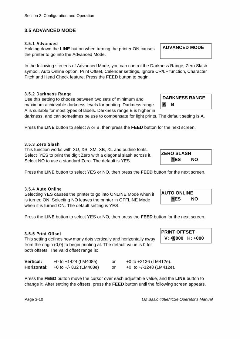
3.5.1 Advanced Holding down the LINE button when turning the printer ON causes the printer to go into the Advanced Mode.
In the following screens of Advanced Mode, you can control the Darkness Range, Zero Slash symbol, Auto Online option, Print Offset, Calendar settings, Ignore CR/LF function, Character Pitch and Head Check feature. Press the FEED button to begin.
3.5.2 Darkness Range Use this setting to choose between two sets of minimum and maximum achievable darkness levels for printing. Darkness range A is suitable for most types of labels. Darkness range B is higher in darkness, and can sometimes be use to compensate for light prints. The default setting is A.
Press the LINE button to select A or B, then press the FEED button for the next screen.
3.5.3 Zero SlashThis function works with XU, XS, XM, XB, XL and outline fonts.Select YES to print the digit Zero with a diagonal slash across it. Select NO to use a standard Zero. The default is YES.
Press the LINE button to select YES or NO, then press the FEED button for the next screen.
3.5.4 Auto OnlineSelecting YES causes the printer to go into ONLINE Mode when it is turned ON. Selecting NO leaves the printer in OFFLINE Mode when it is turned ON. The default setting is YES.
Press the LINE button to select YES or NO, then press the FEED button for the next screen.
3.5.5 Print OffsetThis setting defines how many dots vertically and horizontally away from the origin (0,0) to begin printing at. The default value is 0 for both offsets. The valid offset range is:
Vertical: +0 to +1424 (LM408e) or +0 to +2136 (LM412e). Horizontal: +0 to +/- 832 (LM408e) or +0 to +/-1248 (LM412e).
Press the FEED button move the cursor over each adjustable value, and the LINE button to change it. After setting the offsets, press the FEED button until the following screen appears.
ADVANCED MODE
DARKNESS RANGE A B
ZERO SLASH YES NO
AUTO ONLINE YES NO
PRINT OFFSET V: +0000 H: +000
Section 3: Configuration and Operation
LM Basic 408e/412e Operator’s Manual Page 3-11
3.5 ADVANCED MODE (CONT’D)
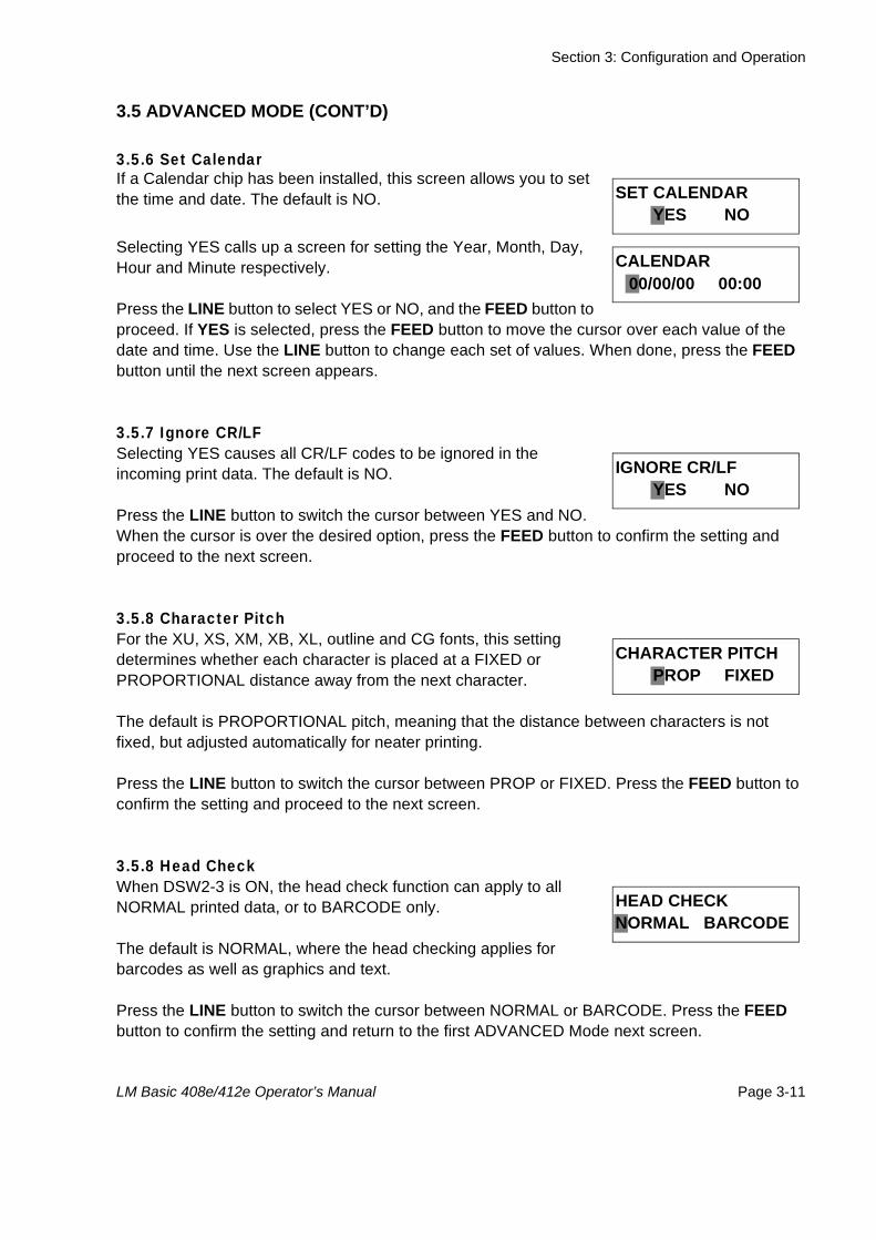
3.5.6 Set Calendar If a Calendar chip has been installed, this screen allows you to set the time and date. The default is NO.
Selecting YES calls up a screen for setting the Year, Month, Day, Hour and Minute respectively.
Press the LINE button to select YES or NO, and the FEED button to proceed. If YES is selected, press the FEED button to move the cursor over each value of the date and time. Use the LINE button to change each set of values. When done, press the FEED button until the next screen appears.
3.5.7 Ignore CR/LF Selecting YES causes all CR/LF codes to be ignored in the incoming print data. The default is NO.
Press the LINE button to switch the cursor between YES and NO. When the cursor is over the desired option, press the FEED button to confirm the setting and proceed to the next screen.
3.5.8 Character Pitch For the XU, XS, XM, XB, XL, outline and CG fonts, this setting determines whether each character is placed at a FIXED or PROPORTIONAL distance away from the next character.
The default is PROPORTIONAL pitch, meaning that the distance between characters is not fixed, but adjusted automatically for neater printing.
Press the LINE button to switch the cursor between PROP or FIXED. Press the FEED button to confirm the setting and proceed to the next screen.
3.5.8 Head CheckWhen DSW2-3 is ON, the head check function can apply to all NORMAL printed data, or to BARCODE only.
The default is NORMAL, where the head checking applies for barcodes as well as graphics and text.
Press the LINE button to switch the cursor between NORMAL or BARCODE. Press the FEED button to confirm the setting and return to the first ADVANCED Mode next screen.
SET CALENDAR YES NO
CALENDAR 00/00/00 00:00
IGNORE CR/LF YES NO
CHARACTER PITCH PROP FIXED
HEAD CHECKNORMAL BARCODE
Section 3: Configuration and Operation
Page 3-12 LM Basic 408e/412e Operator’s Manual
3.6 SERVICE MODE
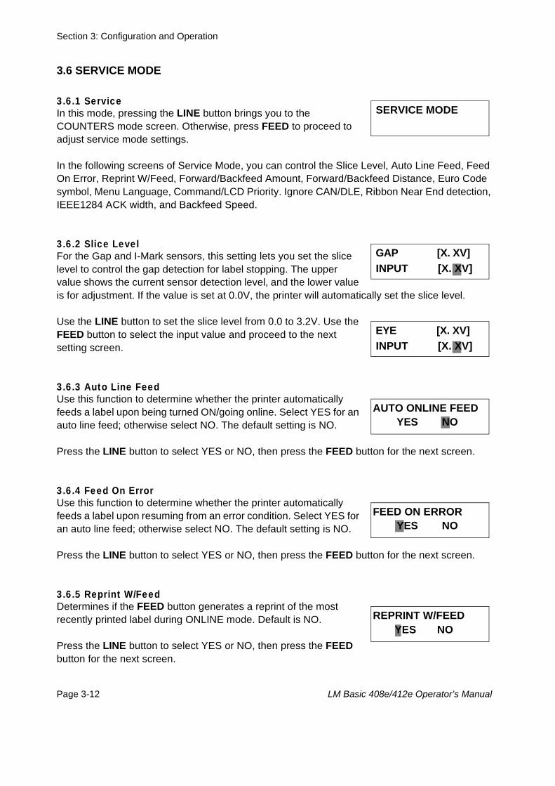
3.6.1 Service In this mode, pressing the LINE button brings you to the COUNTERS mode screen. Otherwise, press FEED to proceed to adjust service mode settings.
In the following screens of Service Mode, you can control the Slice Level, Auto Line Feed, Feed On Error, Reprint W/Feed, Forward/Backfeed Amount, Forward/Backfeed Distance, Euro Code symbol, Menu Language, Command/LCD Priority. Ignore CAN/DLE, Ribbon Near End detection, IEEE1284 ACK width, and Backfeed Speed.
3.6.2 Slice Level For the Gap and I-Mark sensors, this setting lets you set the slice level to control the gap detection for label stopping. The upper value shows the current sensor detection level, and the lower value is for adjustment. If the value is set at 0.0V, the printer will automatically set the slice level.
Use the LINE button to set the slice level from 0.0 to 3.2V. Use the FEED button to select the input value and proceed to the next setting screen.
3.6.3 Auto Line FeedUse this function to determine whether the printer automatically feeds a label upon being turned ON/going online. Select YES for an auto line feed; otherwise select NO. The default setting is NO.
Press the LINE button to select YES or NO, then press the FEED button for the next screen.
3.6.4 Feed On Error Use this function to determine whether the printer automatically feeds a label upon resuming from an error condition. Select YES for an auto line feed; otherwise select NO. The default setting is NO.
Press the LINE button to select YES or NO, then press the FEED button for the next screen.
3.6.5 Reprint W/FeedDetermines if the FEED button generates a reprint of the most recently printed label during ONLINE mode. Default is NO.
Press the LINE button to select YES or NO, then press the FEED button for the next screen.
SERVICE MODE
GAP [X. XV] INPUT [X. XV]
EYE [X. XV] INPUT [X. XV]
AUTO ONLINE FEED YES NO
FEED ON ERROR YES NO
REPRINT W/FEED YES NO
Section 3: Configuration and Operation
LM Basic 408e/412e Operator’s Manual Page 3-13
3.6 SERVICE MODE (CONT’D)
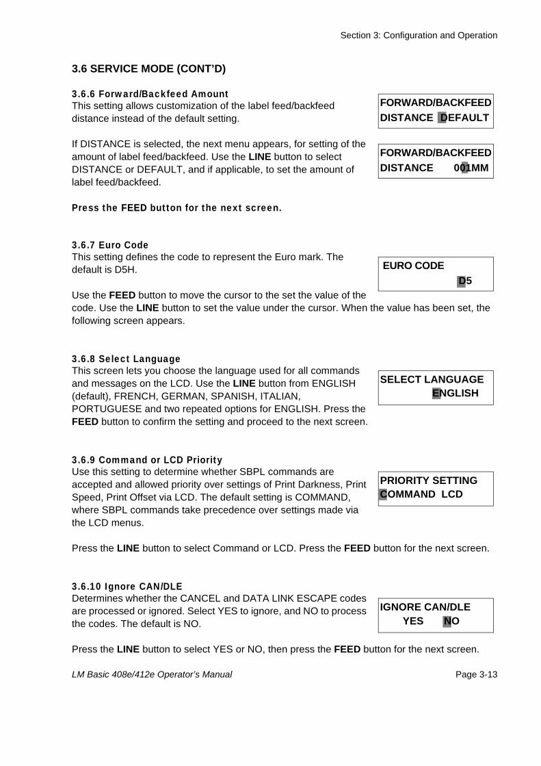
3.6.6 Forward/Backfeed Amount This setting allows customization of the label feed/backfeed distance instead of the default setting.
If DISTANCE is selected, the next menu appears, for setting of the amount of label feed/backfeed. Use the LINE button to select DISTANCE or DEFAULT, and if applicable, to set the amount of label feed/backfeed.
Press the FEED button for the next screen.
3.6.7 Euro Code This setting defines the code to represent the Euro mark. The default is D5H.
Use the FEED button to move the cursor to the set the value of the code. Use the LINE button to set the value under the cursor. When the value has been set, the following screen appears.
3.6.8 Select LanguageThis screen lets you choose the language used for all commands and messages on the LCD. Use the LINE button from ENGLISH (default), FRENCH, GERMAN, SPANISH, ITALIAN, PORTUGUESE and two repeated options for ENGLISH. Press the FEED button to confirm the setting and proceed to the next screen.
3.6.9 Command or LCD PriorityUse this setting to determine whether SBPL commands are accepted and allowed priority over settings of Print Darkness, Print Speed, Print Offset via LCD. The default setting is COMMAND, where SBPL commands take precedence over settings made via the LCD menus.
Press the LINE button to select Command or LCD. Press the FEED button for the next screen.
3.6.10 Ignore CAN/DLEDetermines whether the CANCEL and DATA LINK ESCAPE codes are processed or ignored. Select YES to ignore, and NO to process the codes. The default is NO.
Press the LINE button to select YES or NO, then press the FEED button for the next screen.
FORWARD/BACKFEEDDISTANCE DEFAULT
FORWARD/BACKFEEDDISTANCE 001MM
EURO CODE D5
SELECT LANGUAGE ENGLISH
PRIORITY SETTINGCOMMAND LCD
IGNORE CAN/DLE YES NO
Section 3: Configuration and Operation
Page 3-14 LM Basic 408e/412e Operator’s Manual
3.6 SERVICE MODE (CONT’D)
3.6.11 Ribbon Near End On/OffThis screen lets you enable or disable the early detection and warning of the ribbon supply reaching an end. The default value is ENABLE
Use the LINE button to select ENABLE or DISABLE, then press the FEED button for the next screen.
3.6.12 IEEE1284 ACK Signal If the printer is connected using an IEEE1284 cable, this setting appears. It lets you define the ACK width of the interface from 0.5 to 10.0 microseconds. The default is 0.5 microseconds.
Press the LINE button to rotate the value from 0.5 to 10.0 and back to 0.5 microseconds in steps of 0.1 microsecond. When you are done, press the FEED button to confirm the value and proceed to the final setting of Service Mode.
3.6.13 Backfeed SpeedThe backfeed speed can be left at NORMAL rates or SLOWed down to reduce stress on the media. The default is NORMAL.
Use the LINE button to select either NORMAL or SLOW and then press the FEED button to confirm the setting and return to the main Service Mode screen.
RIBBON NEAR ENDENABLE DISABLE
IEEE1284 ACK SIGNAL 00.5
BACKFEED SPEED NORMAL SLOW
Section 3: Configuration and Operation
LM Basic 408e/412e Operator’s Manual Page 3-15
3.7 COUNTERS MODE
3.7.1 Counters In this mode, pressing the LINE button brings you to the Motion Mode settings. Otherwise, press FEED to proceed to adjust the behavior of the built-in counters.
In the following screens of Counters Mode, you can choose between the Head Counter or Life Counter, see the Head Counter value, clear the Head Counter, and see the Life Counter value.
3.7.2 Counter Select In this screen you can select between the Head counter (HD) or Life counter (LIFE). Use the LINE button to select either counter, then press the FEED button to confirm the setting and proceed to the next setting screen.
3.7.3 Show Head CounterThis screen shows the distance of label printed by the print head.
Press the FEED button for the next screen.
3.7.4 Clear Head CounterIn this screen, you can reset the Head Counter value to 0 by selecting YES. Otherwise, select NO. The default setting is NO.
Press the FEED button for the next screen.
3.7.5 Show Life CounterThis screen shows the distance of label generated by the printer in total.
Press the FEED button for the next screen.
COUNTERS MODE
COUNTERS HD LIFE
HEAD COUNTER X. XM
HEAD COUNT CLEAR YES NO
LIFE COUNTER X. XM
Section 3: Configuration and Operation
Page 3-16 LM Basic 408e/412e Operator’s Manual
3.8 MOVE MODE
3.8.1 Movements of LabelsIn this mode, pressing the LINE button returns you to the main Advance Mode screen. Otherwise, press FEED to proceed to adjust the behavior of the built-in counters.
In the following screens of Move Mode, you can control the following label motion options: Continuous or Tear Off, Pitch Sensor ON/OFF.
3.8.2 Move Mode In this screen you can select between Continuous feeding of labels (where labels are not detached from each other), or Tear Off operation (where each label must be torn off before printing resumes). The default is CONT.
Use the LINE button to select either CONT or TEAR. If CONT is selected, the next screen (Pitch Sensor ON/OFF) appears. Otherwise, the printer returns to the main Move Mode menu. After selecting the Move Mode, press the FEED button to confirm the setting and proceed to the next screen.
3.8.3 Pitch Sensor This screen lets you enable or disable the pitch sensor.
Use the LINE button to select either ON or OFF. The default setting is ON. Then press the FEED button to return to the main Advance Mode screen.
.
MOVE MODE
MOVE MODE CONT TEAR
PITCH SENSOR ON OFF
Section 3: Configuration and Operation
LM Basic 408e/412e Operator’s Manual Page 3-17
3.9 TEST PRINT MODE
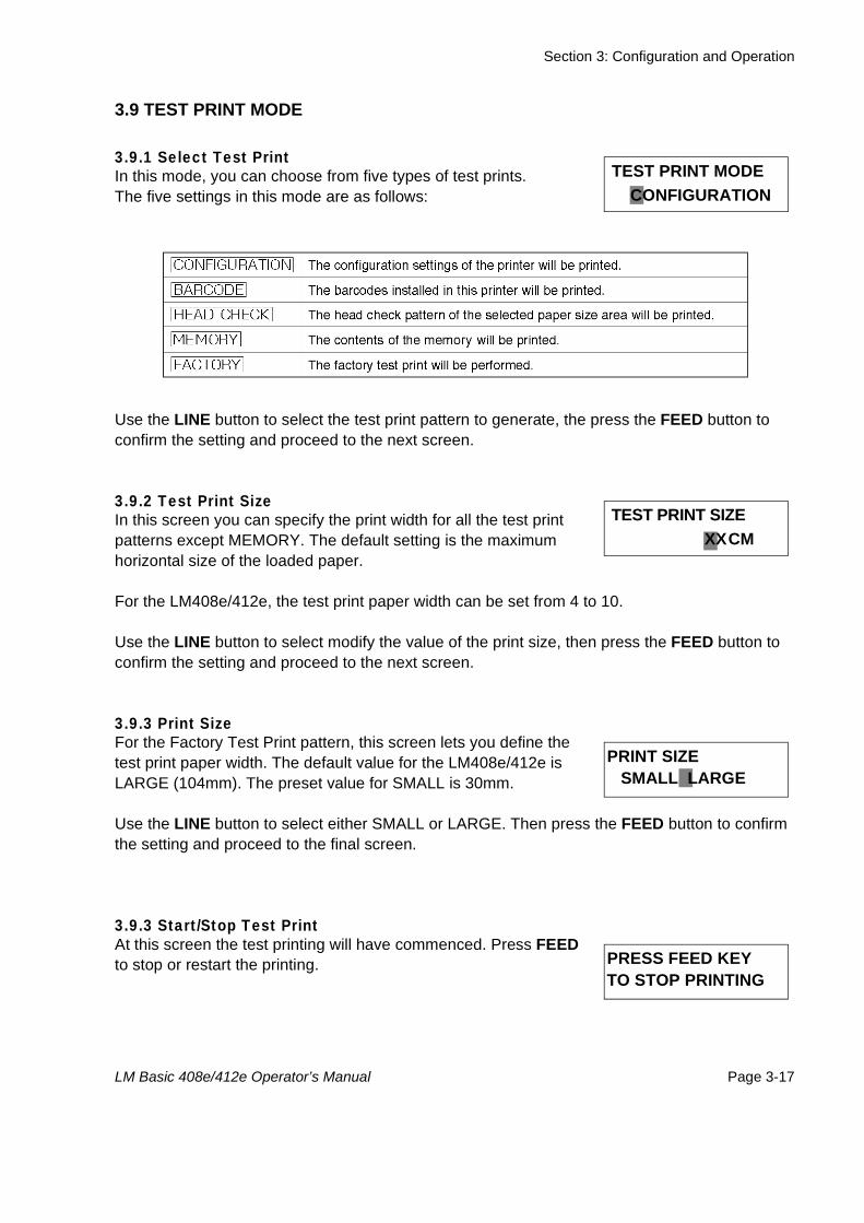
3.9.1 Select Test PrintIn this mode, you can choose from five types of test prints.The five settings in this mode are as follows:
Use the LINE button to select the test print pattern to generate, the press the FEED button to confirm the setting and proceed to the next screen.
3.9.2 Test Print Size In this screen you can specify the print width for all the test print patterns except MEMORY. The default setting is the maximum horizontal size of the loaded paper.
For the LM408e/412e, the test print paper width can be set from 4 to 10.
Use the LINE button to select modify the value of the print size, then press the FEED button to confirm the setting and proceed to the next screen.
3.9.3 Print SizeFor the Factory Test Print pattern, this screen lets you define the test print paper width. The default value for the LM408e/412e is LARGE (104mm). The preset value for SMALL is 30mm.
Use the LINE button to select either SMALL or LARGE. Then press the FEED button to confirm the setting and proceed to the final screen.
3.9.3 Start/Stop Test PrintAt this screen the test printing will have commenced. Press FEED to stop or restart the printing.
TEST PRINT MODE CONFIGURATION
TEST PRINT SIZE XXCM
PRINT SIZE SMALL LARGE
PRESS FEED KEYTO STOP PRINTING
Section 3: Configuration and Operation
Page 3-18 LM Basic 408e/412e Operator’s Manual
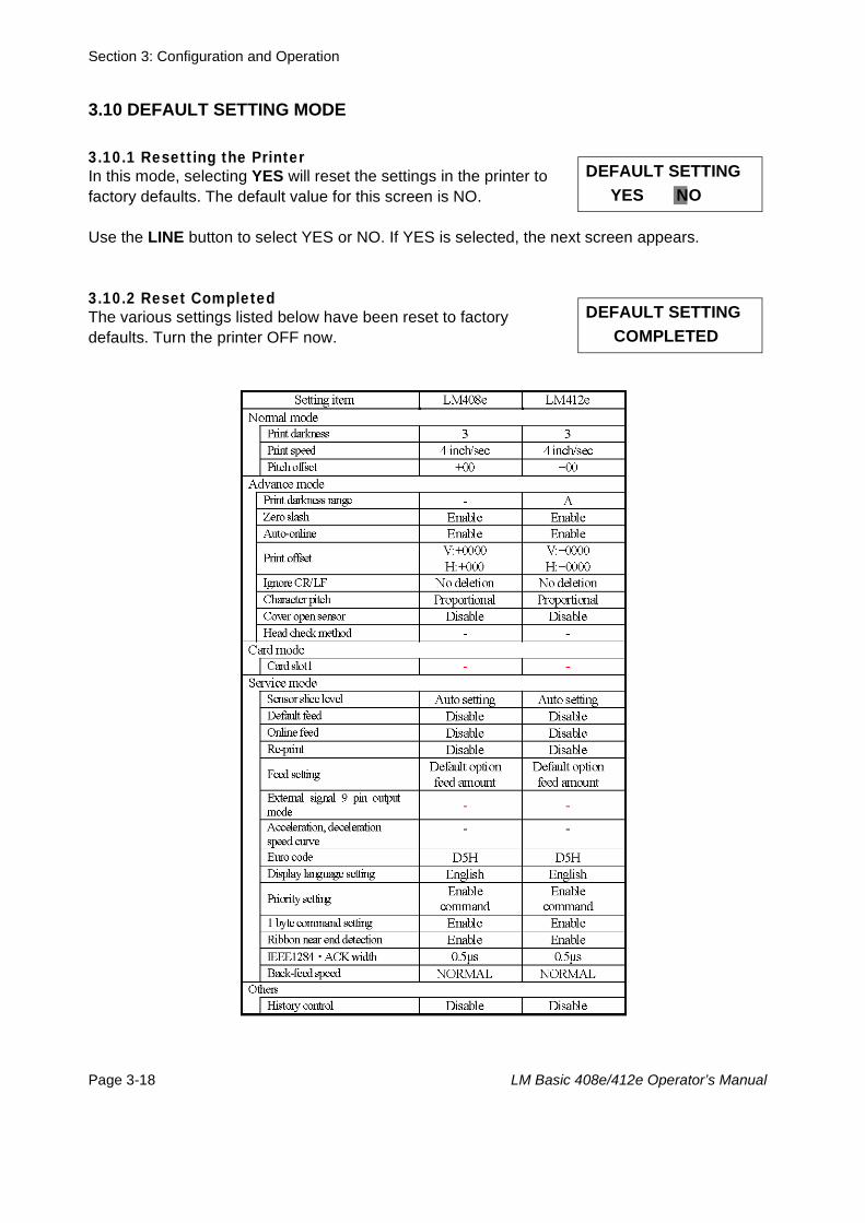
3.10 DEFAULT SETTING MODE
3.10.1 Resetting the Printer In this mode, selecting YES will reset the settings in the printer to factory defaults. The default value for this screen is NO.
Use the LINE button to select YES or NO. If YES is selected, the next screen appears.
3.10.2 Reset Completed The various settings listed below have been reset to factory defaults. Turn the printer OFF now.
DEFAULT SETTING YES NO
DEFAULT SETTING COMPLETED
Section 3: Configuration and Operation
LM Basic 408e/412e Operator’s Manual Page 3-19
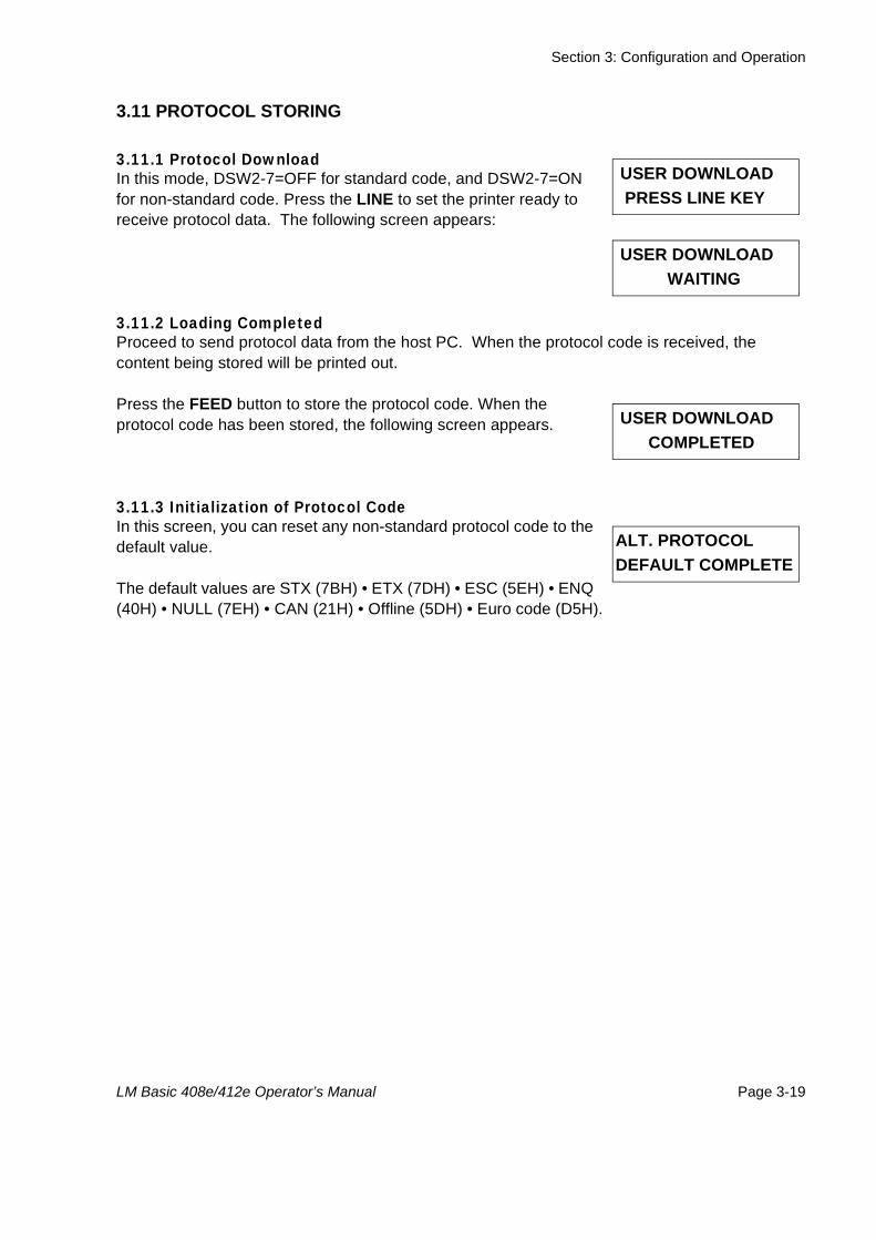
3.11 PROTOCOL STORING
3.11.1 Protocol Download In this mode, DSW2-7=OFF for standard code, and DSW2-7=ON for non-standard code. Press the LINE to set the printer ready to receive protocol data. The following screen appears:
3.11.2 Loading Completed Proceed to send protocol data from the host PC. When the protocol code is received, the content being stored will be printed out.
Press the FEED button to store the protocol code. When the protocol code has been stored, the following screen appears.
3.11.3 Initialization of Protocol Code In this screen, you can reset any non-standard protocol code to the default value.
The default values are STX (7BH) • ETX (7DH) • ESC (5EH) • ENQ (40H) • NULL (7EH) • CAN (21H) • Offline (5DH) • Euro code (D5H).
USER DOWNLOAD PRESS LINE KEY
USER DOWNLOAD WAITING
USER DOWNLOAD COMPLETED
ALT. PROTOCOLDEFAULT COMPLETE
Section 3: Configuration and Operation
Page 3-20 LM Basic 408e/412e Operator’s Manual
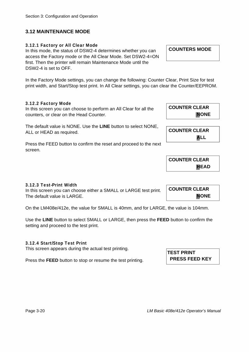
3.12 MAINTENANCE MODE
3.12.1 Factory or All Clear Mode In this mode, the status of DSW2-4 determines whether you can access the Factory mode or the All Clear Mode. Set DSW2-4=ON first. Then the printer will remain Maintenance Mode until the DSW2-4 is set to OFF.
In the Factory Mode settings, you can change the following: Counter Clear, Print Size for test print width, and Start/Stop test print. In All Clear settings, you can clear the Counter/EEPROM.
3.12.2 Factory Mode In this screen you can choose to perform an All Clear for all the counters, or clear on the Head Counter.
The default value is NONE. Use the LINE button to select NONE, ALL or HEAD as required.
Press the FEED button to confirm the reset and proceed to the next screen.
3.12.3 Test-Print Width In this screen you can choose either a SMALL or LARGE test print. The default value is LARGE.
On the LM408e/412e, the value for SMALL is 40mm, and for LARGE, the value is 104mm.
Use the LINE button to select SMALL or LARGE, then press the FEED button to confirm the setting and proceed to the test print.
3.12.4 Start/Stop Test PrintThis screen appears during the actual test printing.
Press the FEED button to stop or resume the test printing.
COUNTERS MODE
COUNTER CLEAR NONE
COUNTER CLEAR ALL COUNTER CLEAR ALL
COUNTER CLEAR HEAD
COUNTER CLEAR NONE
TEST PRINT PRESS FEED KEY
Section 3: Configuration and Operation
LM Basic 408e/412e Operator’s Manual Page 3-21
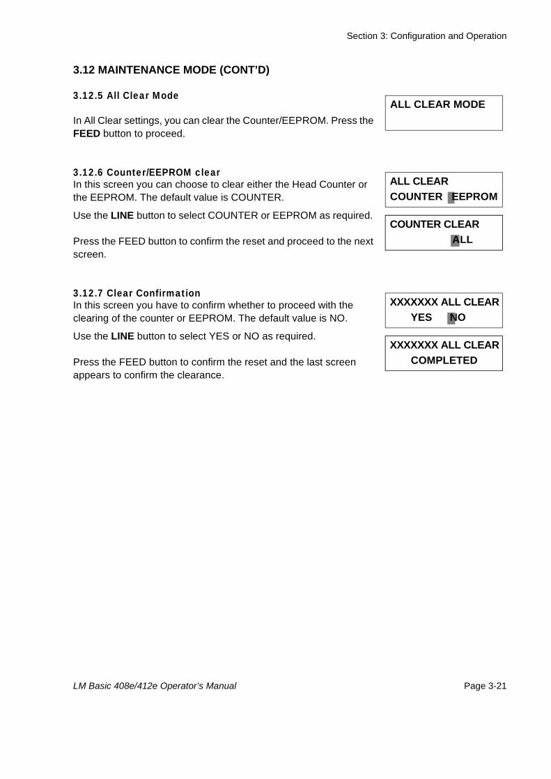
3.12 MAINTENANCE MODE (CONT’D)
3.12.5 All Clear Mode
In All Clear settings, you can clear the Counter/EEPROM. Press the FEED button to proceed.
3.12.6 Counter/EEPROM clearIn this screen you can choose to clear either the Head Counter or the EEPROM. The default value is COUNTER.
Use the LINE button to select COUNTER or EEPROM as required.
Press the FEED button to confirm the reset and proceed to the next screen.
3.12.7 Clear ConfirmationIn this screen you have to confirm whether to proceed with the clearing of the counter or EEPROM. The default value is NO.
Use the LINE button to select YES or NO as required.
Press the FEED button to confirm the reset and the last screen appears to confirm the clearance.
ALL CLEAR MODE
ALL CLEAR COUNTER EEPROM
COUNTER CLEAR ALL COUNTER CLEAR ALL
XXXXXXX ALL CLEAR YES NO
COUNTER CLEAR ALL XXXXXXX ALL CLEAR COMPLETED

Section 3: Configuration and Operation
Page 3-22 LM Basic 408e/412e Operator’s Manual
3.13 HEX DUMP MODE
3.13.1 LCD Status In the Hex Dump Mode, when data is received, a hex dump is printed. The LCD screen then shows the quantity of labels printed, and the printer status.
3.13.2 Hex Dump Mode in buffer In this mode, only the buffer data is dumped. The quantity of labels printed is updated on the LCD screen.
The procedure for such a buffer dump is as follows:
1. Make sure the printer is turned OFF.2. Set DSW2-4 to ON, then press the LINE button to take the printer ONLINE. 4. Send data to the printer.5. To return to normal mode, turn the printer OFF and set DSW2-4 to OFF.6. Finally, turn the printer ON again to let the new mode take effect.
ONLINE QTY: 000000
ONLINE QTY: 000000
Section 3: Configuration and Operation
LM Basic 408e/412e Operator’s Manual Page 3-23
3.14 DOWNLOAD MODE
3.14.1 LCD Status In the mode, the LCD shows whether the printer is ready to receive the Flash Download. At the screen shown here, proceed to send the program/font/command data from the host PC.
The following screen then appears. The “>” sign is used to show the progress of the data transfer.
1. “>” means downloading has started.2. “>>” means 1Mb of data has been received and processed.3. “>>>” means 3Mb of data has been received and processed.4. “>>>>” means the data transfer has completed.5. “>>>>>” means that some data is being checked.6. “>>>>>>” means the all data is being verified.7. “>>>>>>>” means that the data has been verified and written to memory.
Do NOT turn the printer OFF when the printer is downloading data to Flash memory.When the entire process is complete, the following screen appears:
Press the FEED button to return to the main Download Mode screen.
FLASH DOWNLOAD READY
XXXXXXX DOWNLOAD START>>>>>>>END
DOWNLOADCOMPLETE PRESS FEED KEY
Section 3: Configuration and Operation
Page 3-24 LM Basic 408e/412e Operator’s Manual
3.15 BOOT DOWNLOAD MODE
3.15.1 LCD Status In the mode, the LCD shows the Boot Downloader prompt. Press the FEED button to prepare the printer for the data.
The following screen then appears. Start sending the data from the host PC.
The next screen then appears:The “>” sign is used to show the progress of the data transfer.
1. “>” means downloading has started.2. “>>” means 1Mb of data has been received and processed.3. “>>>” means 3Mb of data has been received and processed.4. “>>>>” means the data transfer has completed.5. “>>>>>” means that some data is being checked.6. “>>>>>>” means the all data is being verified.7. “>>>>>>>” means that the data has been verified and written to memory.
Do NOT turn the printer OFF when the printer is downloading data to memory.When the entire process is complete, the following screen appears:
Press the FEED button to return to the main Download Mode screen.
BOOT DOWNLOADER PRESS FEED KEY
PROGRAM DOWNLOAD READY
PROGRAM DOWNLOAD START>>>>>>>END
DOWNLOADCOMPLETE PRESS FEED KEY
Section 4: Cleaning and Maintenance
LM Basic 408e/412e Operator’s Manual Page 4-1
4CLEANING AND MAINTENANCE
4.1 INTRODUCTION
This section provides information on user maintenance for the LM Basic printer. Thefollowing information is covered here:
• Cleaning the Print Head, Platen and Rollers• Adjusting print quality• Replacing the protective fuse • Replacing the protective Print Head
4.2 CLEANING THE PRINT HEAD, PLATEN AND ROLLERSThe print head not only generates printouts of barcodes, but also graphics and text. To produce optimal printing, it must be kept clean in spite of the dirt and adhesive that constantly accumulates on its print surface. Furthermore, dirt can accumulated along the label path, affecting parts like sensors and guides, and reducing their performance.
Therefore, it is important to clean these important components periodically. This is done with a printer cleaning kit or cleaning sheets (for print head cleaning only), available separately from your authorized SATO dealer. When the cleaning materials run out, be sure to obtain only certified replacements from your dealer.
When to clean with a cleaning kit♦ For the print head, platen roller, paper sensor, and label guide: clean after using up every other
roll of paper, or each time after printing 150 m.
♦ For other parts: clean after finishing every six rolls of paper, or every time after printing 900 m.
When to clean with the cleaning sheet♦ For the print head, clean after using every six rolls of paper, or every time after printing 900 m.
Section 4: Cleaning and Maintenance
Page 4-2 LM Basic 408e/412e Operator’s Manual
4.3 HOW TO CLEAN THE PRINTER (WITH A CLEANING SET)
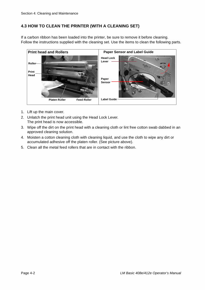
If a carbon ribbon has been loaded into the printer, be sure to remove it before cleaning. Follow the instructions supplied with the cleaning set. Use the items to clean the following parts.
1. Lift up the main cover.2. Unlatch the print head unit using the Head Lock Lever.
The print head is now accessible.3. Wipe off the dirt on the print head with a cleaning cloth or lint free cotton swab dabbed in an
approved cleaning solution.4. Moisten a cotton cleaning cloth with cleaning liquid, and use the cloth to wipe any dirt or
accumulated adhesive off the platen roller. (See picture above). 5. Clean all the metal feed rollers that are in contact with the ribbon.
Print head and Rollers Paper Sensor and Label Guide
Platen Roller
Print Head
Feed Roller
Roller
Paper Sensor
Head Lock Lever
Label Guide
Section 4: Cleaning and Maintenance
LM Basic 408e/412e Operator’s Manual Page 4-3
4.4 HOW TO CLEAN THE PRINTER (CLEANING SHEET)
The cleaning sheet is used for cleaning stubborn stains on the print head.
1. Lift up the front cover.2. Unlatch the print head unit using the purple Head Lock lever. The print head is now accessi-
ble.3. Remove the label and ribbon.4. Put the head cleaning sheet between the print head and the platen roller. The coarse side of
the cleaning sheet should face the surface of the print head elements.5. Fasten the Head Lock lever to mount the print head.6. Using both hands, pull the cleaning sheet outwards, toward your body. This will remove any
dirt stuck to the print head. (See picture on the right)7. When the cleaning sheet has been removed, perform steps 2 to 6 to repeat the cleaning pro-
cedure one or two more times. 8. When no more additional dirt appears on the cleaning sheet after it has been pulled out, you
can stop cleaning with the sheet.9. Unlatch the print head and use the cleaning cloth from the cleaning kit to gently remove any
remaining dirt from the print head.
Caution• Be sure to turn off the power before cleaning.• The suggested cleaning schedule here are just guidelines. If necessary, clean as appropriate depending
on the degree of contamination.
• Use a cleaning pen (for the print head only) or cotton cloth to clean the printer units.
• Use only soft, lint-free materials for cleaning. Avoid using hard objects for the cleaning process, as theywill damage the components.
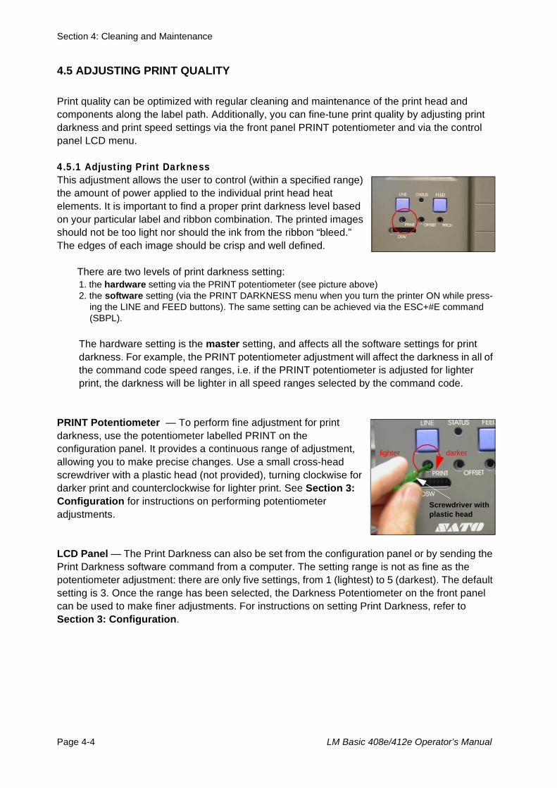
Section 4: Cleaning and Maintenance
Page 4-4 LM Basic 408e/412e Operator’s Manual
4.5 ADJUSTING PRINT QUALITY
Print quality can be optimized with regular cleaning and maintenance of the print head and components along the label path. Additionally, you can fine-tune print quality by adjusting print darkness and print speed settings via the front panel PRINT potentiometer and via the control panel LCD menu.
4.5.1 Adjusting Print Darkness This adjustment allows the user to control (within a specified range) the amount of power applied to the individual print head heat elements. It is important to find a proper print darkness level based on your particular label and ribbon combination. The printed images should not be too light nor should the ink from the ribbon “bleed.” The edges of each image should be crisp and well defined.
There are two levels of print darkness setting: 1. the hardware setting via the PRINT potentiometer (see picture above) 2. the software setting (via the PRINT DARKNESS menu when you turn the printer ON while press-
ing the LINE and FEED buttons). The same setting can be achieved via the ESC+#E command (SBPL).
The hardware setting is the master setting, and affects all the software settings for print darkness. For example, the PRINT potentiometer adjustment will affect the darkness in all of the command code speed ranges, i.e. if the PRINT potentiometer is adjusted for lighterprint, the darkness will be lighter in all speed ranges selected by the command code.
PRINT Potentiometer — To perform fine adjustment for print darkness, use the potentiometer labelled PRINT on the configuration panel. It provides a continuous range of adjustment, allowing you to make precise changes. Use a small cross-head screwdriver with a plastic head (not provided), turning clockwise for darker print and counterclockwise for lighter print. See Section 3: Configuration for instructions on performing potentiometer adjustments.
LCD Panel — The Print Darkness can also be set from the configuration panel or by sending the Print Darkness software command from a computer. The setting range is not as fine as the potentiometer adjustment: there are only five settings, from 1 (lightest) to 5 (darkest). The default setting is 3. Once the range has been selected, the Darkness Potentiometer on the front panel can be used to make finer adjustments. For instructions on setting Print Darkness, refer to Section 3: Configuration.
darkerlighter
Screwdriver with plastic head
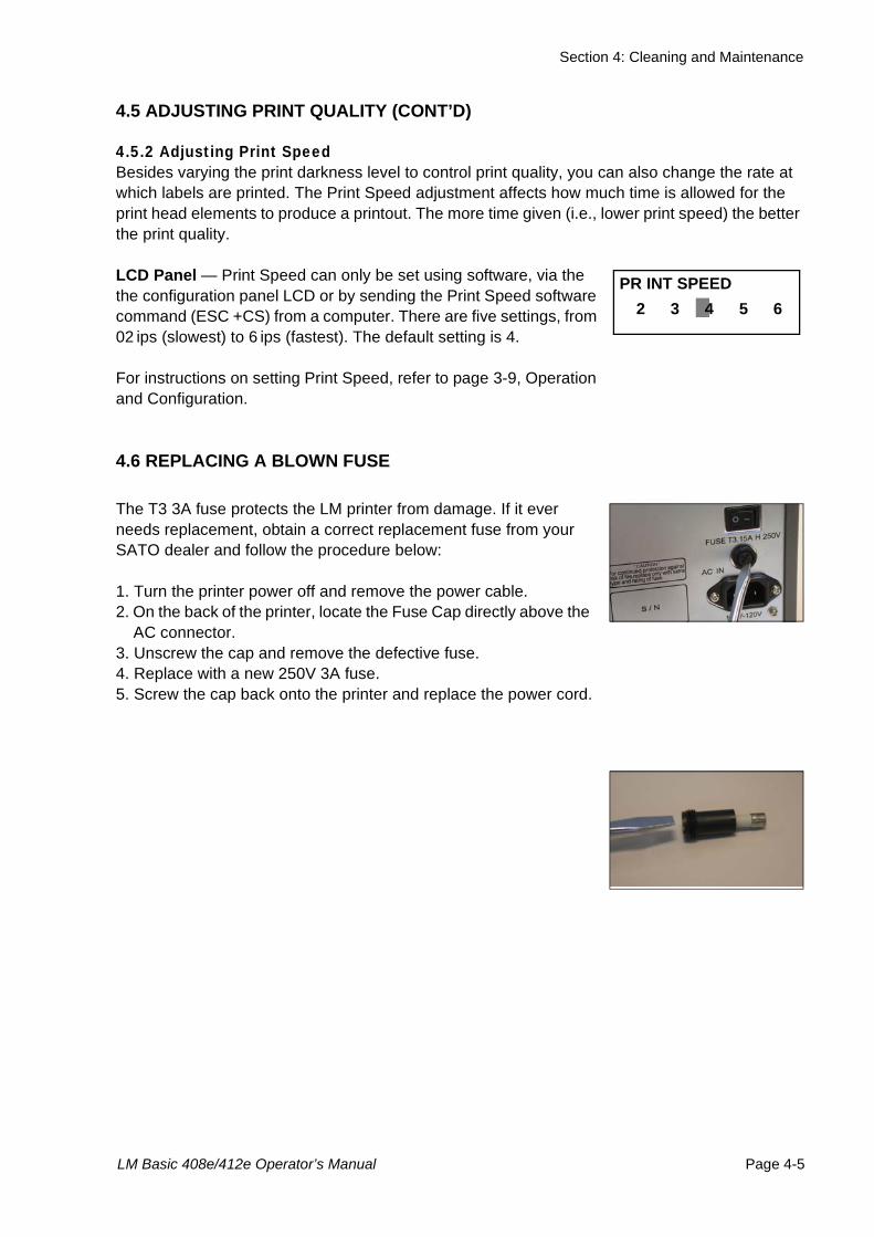
Section 4: Cleaning and Maintenance
LM Basic 408e/412e Operator’s Manual Page 4-5
4.5 ADJUSTING PRINT QUALITY (CONT’D)
4.5.2 Adjusting Print Speed Besides varying the print darkness level to control print quality, you can also change the rate at which labels are printed. The Print Speed adjustment affects how much time is allowed for the print head elements to produce a printout. The more time given (i.e., lower print speed) the better the print quality.
LCD Panel — Print Speed can only be set using software, via the the configuration panel LCD or by sending the Print Speed software command (ESC +CS) from a computer. There are five settings, from 02 ips (slowest) to 6 ips (fastest). The default setting is 4.
For instructions on setting Print Speed, refer to page 3-9, Operation and Configuration.
4.6 REPLACING A BLOWN FUSE
The T3 3A fuse protects the LM printer from damage. If it ever needs replacement, obtain a correct replacement fuse from your SATO dealer and follow the procedure below:
1. Turn the printer power off and remove the power cable.2. On the back of the printer, locate the Fuse Cap directly above the
AC connector.3. Unscrew the cap and remove the defective fuse.4. Replace with a new 250V 3A fuse.5. Screw the cap back onto the printer and replace the power cord.
PR INT SPEED 2 3 4 5 6

Section 4: Cleaning and Maintenance
Page 4-6 LM Basic 408e/412e Operator’s Manual
This page is intentionally left blank
Section 5: Interface Specifications
LM Basic 408e/412e Operator’s Manual Page 5-1
5INTERFACE SPECIFICATIONS
5.1 INTERFACE TYPESThe LM printer is supplied with a single interface of the user’s choice: typically a parallel interface is used for transmitting data to and from the host. However, note that no external signal interface is available as an option for connecting the printer to other peripherals.
The following are the different types of interface boards available:
1) RS232C Interface Board
2) IEEE 1284 Interface Board
3) USB Interface Board (Ver. 1.1)
4) LAN Interface Board (10Base-T/100Base-T)
5) IEEE 802.11b Wireless LAN Interface Board
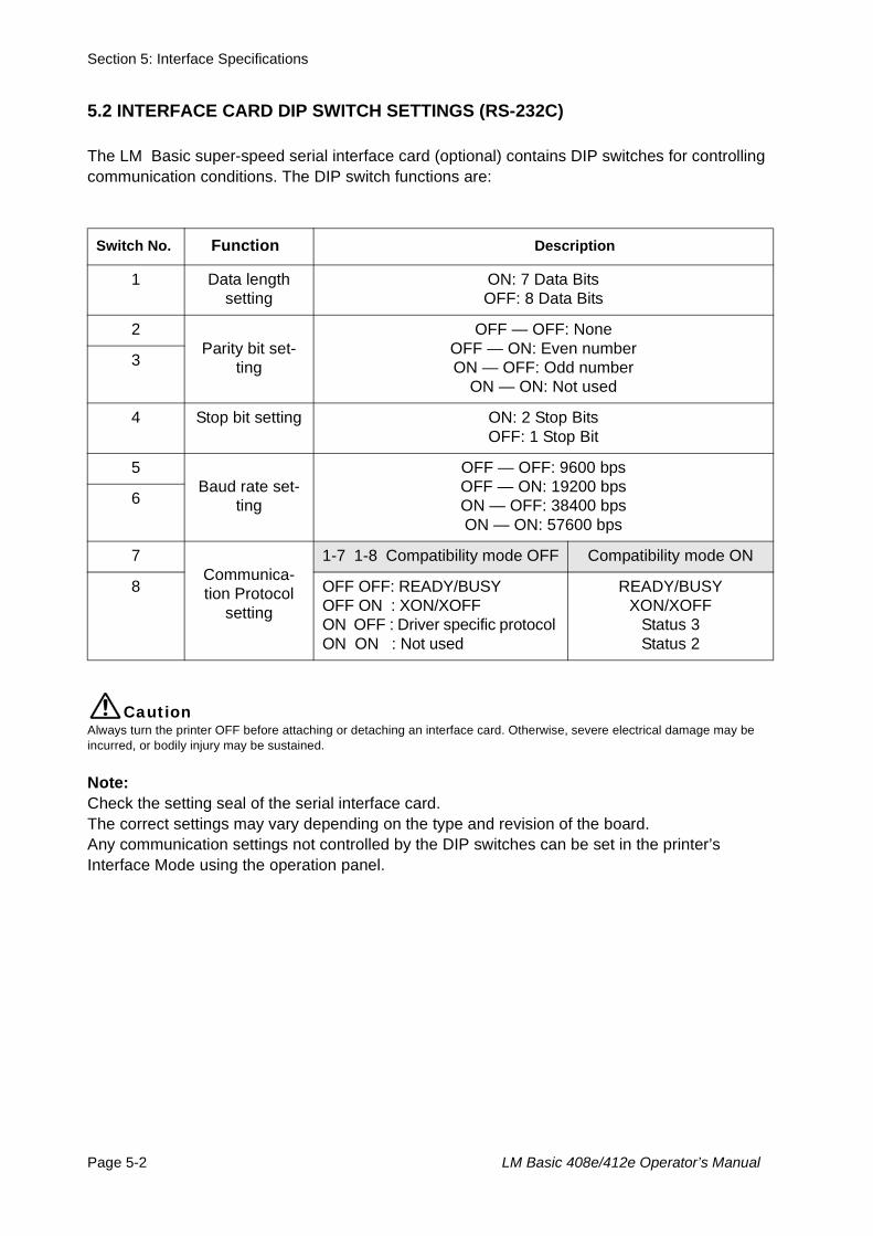
Section 5: Interface Specifications
Page 5-2 LM Basic 408e/412e Operator’s Manual
5.2 INTERFACE CARD DIP SWITCH SETTINGS (RS-232C)
The LM Basic super-speed serial interface card (optional) contains DIP switches for controlling communication conditions. The DIP switch functions are:
CautionAlways turn the printer OFF before attaching or detaching an interface card. Otherwise, severe electrical damage may be incurred, or bodily injury may be sustained.
Note:Check the setting seal of the serial interface card. The correct settings may vary depending on the type and revision of the board.Any communication settings not controlled by the DIP switches can be set in the printer’s Interface Mode using the operation panel.
Switch No. Function Description
1 Data length setting
ON: 7 Data BitsOFF: 8 Data Bits
2Parity bit set-
ting
OFF — OFF: NoneOFF — ON: Even numberON — OFF: Odd number
ON — ON: Not used3
4 Stop bit setting ON: 2 Stop BitsOFF: 1 Stop Bit
5Baud rate set-
ting
OFF — OFF: 9600 bpsOFF — ON: 19200 bpsON — OFF: 38400 bpsON — ON: 57600 bps
6
7Communica-tion Protocol
setting
1-7 1-8 Compatibility mode OFF Compatibility mode ON
8 OFF OFF: READY/BUSY OFF ON : XON/XOFF ON OFF : Driver specific protocol ON ON : Not used
READY/BUSYXON/XOFF
Status 3Status 2
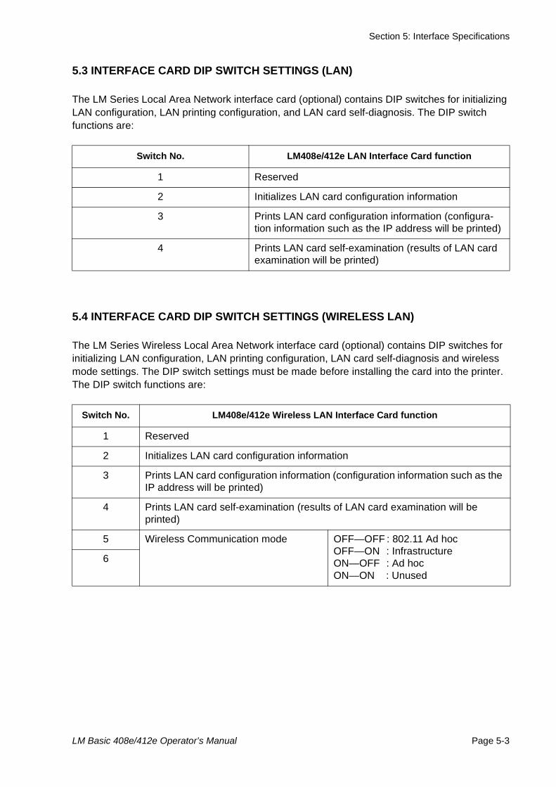
Section 5: Interface Specifications
LM Basic 408e/412e Operator’s Manual Page 5-3
5.3 INTERFACE CARD DIP SWITCH SETTINGS (LAN)
The LM Series Local Area Network interface card (optional) contains DIP switches for initializing LAN configuration, LAN printing configuration, and LAN card self-diagnosis. The DIP switch functions are:
5.4 INTERFACE CARD DIP SWITCH SETTINGS (WIRELESS LAN)
The LM Series Wireless Local Area Network interface card (optional) contains DIP switches for initializing LAN configuration, LAN printing configuration, LAN card self-diagnosis and wireless mode settings. The DIP switch settings must be made before installing the card into the printer. The DIP switch functions are:
Switch No. LM408e/412e LAN Interface Card function
1 Reserved
2 Initializes LAN card configuration information
3 Prints LAN card configuration information (configura-tion information such as the IP address will be printed)
4 Prints LAN card self-examination (results of LAN card examination will be printed)
Switch No. LM408e/412e Wireless LAN Interface Card function
1 Reserved
2 Initializes LAN card configuration information
3 Prints LAN card configuration information (configuration information such as the IP address will be printed)
4 Prints LAN card self-examination (results of LAN card examination will be printed)
5 Wireless Communication mode OFF—OFF : 802.11 Ad hocOFF—ON : InfrastructureON—OFF : Ad hocON—ON : Unused
6
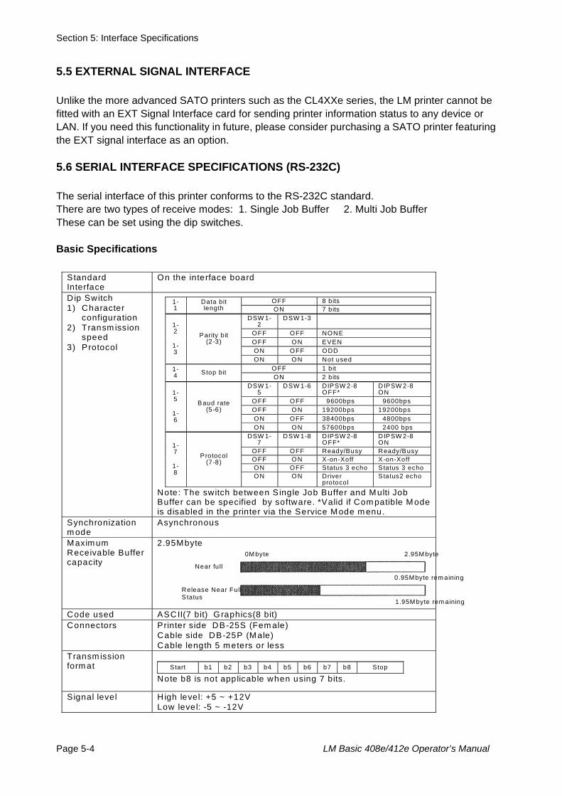
Section 5: Interface Specifications
Page 5-4 LM Basic 408e/412e Operator’s Manual
5.5 EXTERNAL SIGNAL INTERFACE
Unlike the more advanced SATO printers such as the CL4XXe series, the LM printer cannot be fitted with an EXT Signal Interface card for sending printer information status to any device or LAN. If you need this functionality in future, please consider purchasing a SATO printer featuring the EXT signal interface as an option.
5.6 SERIAL INTERFACE SPECIFICATIONS (RS-232C)
The serial interface of this printer conforms to the RS-232C standard.There are two types of receive modes: 1. Single Job Buffer 2. Multi Job BufferThese can be set using the dip switches.
Basic Specifications
Standard Interface
On the interface board
D ip Switch 1) Character
configuration 2) Transm ission
speed 3) Protocol
OFF 8 bits 1-
1 Data bit length ON 7 bits
DSW 1-2
DSW 1-3
OFF OFF NONE OFF O N EVEN ON OFF ODD
1-2
1-3
Parity bit (2-3)
ON O N Not used OFF 1 bit 1-
4 Stop bit ON 2 bits
DSW 1-5
DSW 1-6 DIPSW 2-8 OFF*
D IPSW 2-8 ON
OFF OFF 9600bps 9600bps OFF O N 19200bps 19200bps ON OFF 38400bps 4800bps
1-5
1-6
Baud rate (5-6)
ON O N 57600bps 2400 bps DSW 1-
7 DSW 1-8 DIPSW 2-8
OFF* D IPSW 2-8 ON
OFF OFF Ready/Busy Ready/Busy OFF O N X-on-Xoff X-on-Xoff ON OFF Status 3 echo S tatus 3 echo
1-7
1-8
P rotocol (7-8)
ON O N Driver protocol
S tatus2 echo
Note: The switch between Single Job Buffer and Multi Job Buffer can be specified by software. *Valid if Com patible Mode is disabled in the printer via the Service Mode m enu.
Synchronization m ode
Asynchronous
Maximum Receivable Buffer capacity
2.95Mbyte
Code used ASCII(7 bit) Graphics(8 bit) Connectors
Printer side DB-25S (Fem ale) Cable side DB-25P (Male) Cable length 5 meters or less
Transm ission form at
Start b1 b2 b3 b4 b5 b6 b7 b8 Stop
Note b8 is not applicable when using 7 bits.
S ignal level
H igh level: +5 ~ +12V Low level: -5 ~ -12V
Near full
Release Near Full S tatus
2.95M byte
0.95Mbyte rem aining
1.95M byte rem aining
0M byte
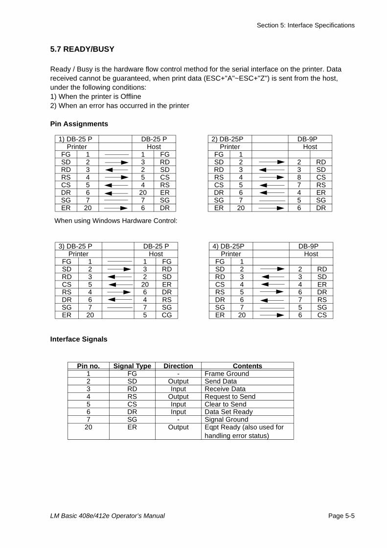
Section 5: Interface Specifications
LM Basic 408e/412e Operator’s Manual Page 5-5
5.7 READY/BUSY
Ready / Busy is the hardware flow control method for the serial interface on the printer. Data received cannot be guaranteed, when print data (ESC+"A"~ESC+"Z") is sent from the host, under the following conditions:1) When the printer is Offline2) When an error has occurred in the printer
Pin Assignments
Interface Signals
When using Windows Hardware Control:
1) DB-25 P DB-25 P 2) DB-25P DB-9PPrinter Host Printer Host
FG 1 1 FG FG 1SD 2 3 RD SD 2 2 RDRD 3 2 SD RD 3 3 SDRS 4 5 CS RS 4 8 CSCS 5 4 RS CS 5 7 RSDR 6 20 ER DR 6 4 ERSG 7 7 SG SG 7 5 SGER 20 6 DR ER 20 6 DR
3) DB-25 P DB-25 P 4) DB-25P DB-9PPrinter Host Printer Host
FG 1 1 FG FG 1SD 2 3 RD SD 2 2 RDRD 3 2 SD RD 3 3 SDCS 5 20 ER CS 4 4 ERRS 4 6 DR RS 5 6 DRDR 6 4 RS DR 6 7 RSSG 7 7 SG SG 7 5 SGER 20 5 CG ER 20 6 CS
Pin no. Signal Type Direction Contents1 FG - Frame Ground2 SD Output Send Data3 RD Input Receive Data4 RS Output Request to Send5 CS Input Clear to Send6 DR Input Data Set Ready7 SG - Signal Ground
20 ER Output Eqpt Ready (also used for handling error status)
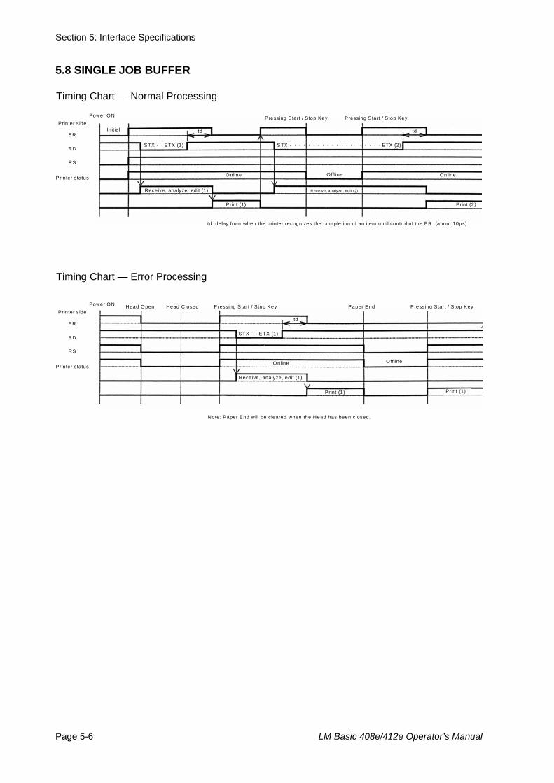
Section 5: Interface Specifications
Page 5-6 LM Basic 408e/412e Operator’s Manual
5.8 SINGLE JOB BUFFER
Timing Chart — Normal Processing
Power O N Printer s ide
ER
RD
RS
Printer status
Initial td
Pressing Start / Stop Key Pressing Start / Stop Key
td
STX · · ETX (1) STX · · · · · · · · · · · · · · · · · · · · ETX (2)
O nline Offline Online
Receive, analyze, edit (1) R eceive, analyze, edit (2)
Print (1) Print (2)
td: delay from when the printer recognizes the com pletion of an item until control of the ER. (about 10µs)
Timing Chart — Error Processing
Power ON Printer s ide
ER
RD
RS
Printer status
Head Open
td
Paper End Pressing Start / Stop Key
STX · · ETX (1)
O nline Offline
Receive, analyze, edit (1)
Print (1) Print (1)
Note: Paper End will be cleared when the Head has been closed.
Head Closed Pressing Start / Stop Key
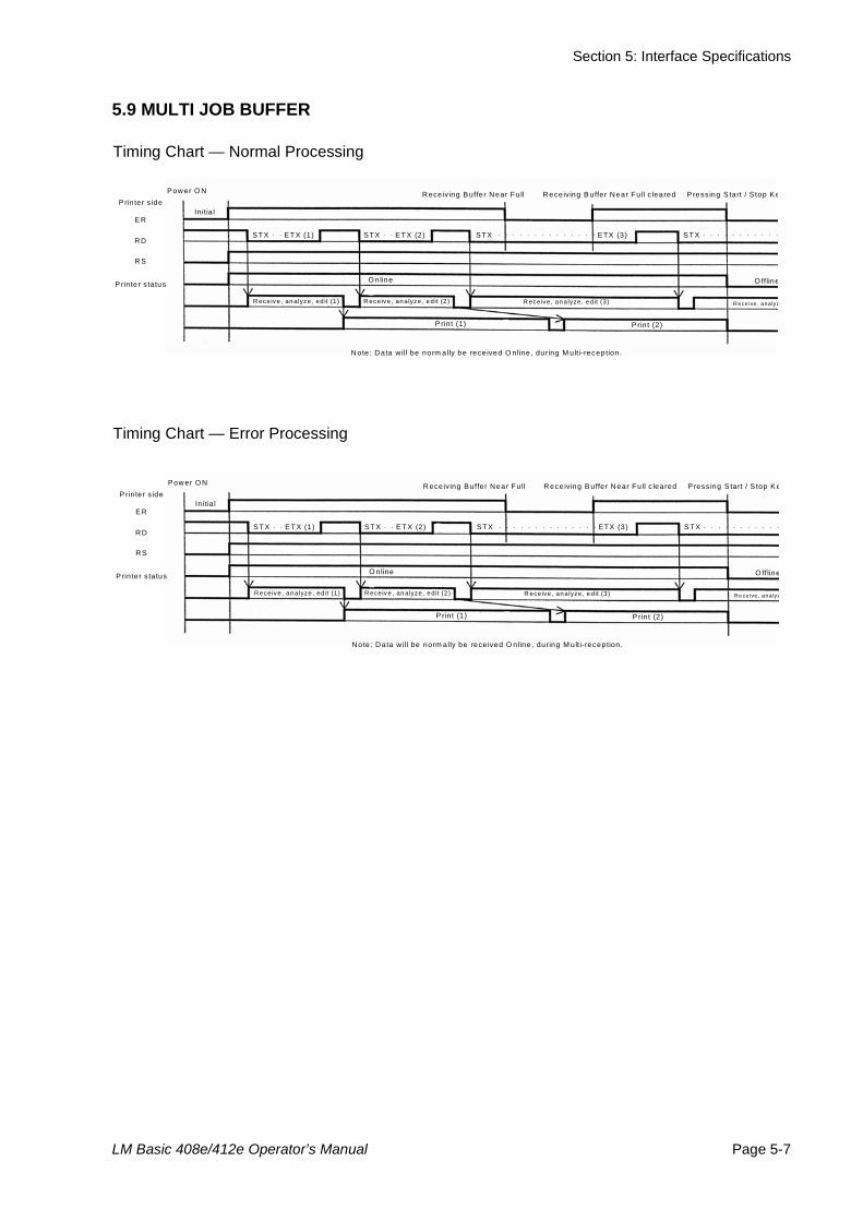
Section 5: Interface Specifications
LM Basic 408e/412e Operator’s Manual Page 5-7
5.9 MULTI JOB BUFFER
Timing Chart — Normal Processing
Timing Chart — Error Processing
Power O N
P rin ter s ide
E R
RD
RS
P rin ter s tatus
Initia l
Receiving B uffer Near Fu ll Receiving B uffer Near Fu ll c leared
S TX · · E TX (1) S TX · · · · · · · · · · ·
O nline O ffline
R eceive, analyze, ed it (1) R eceive, analyze, edit (3)
P rin t (1) P rin t (2)
Note: Data will be norm ally be rece ived O nline, during M ulti-reception.
P ress ing S tart / S top K e
S TX · · E TX (2) STX · · · · · · · · · · · · · · ETX (3)
R eceive, analyze, edit (2 ) R e ce ive , ana lyz
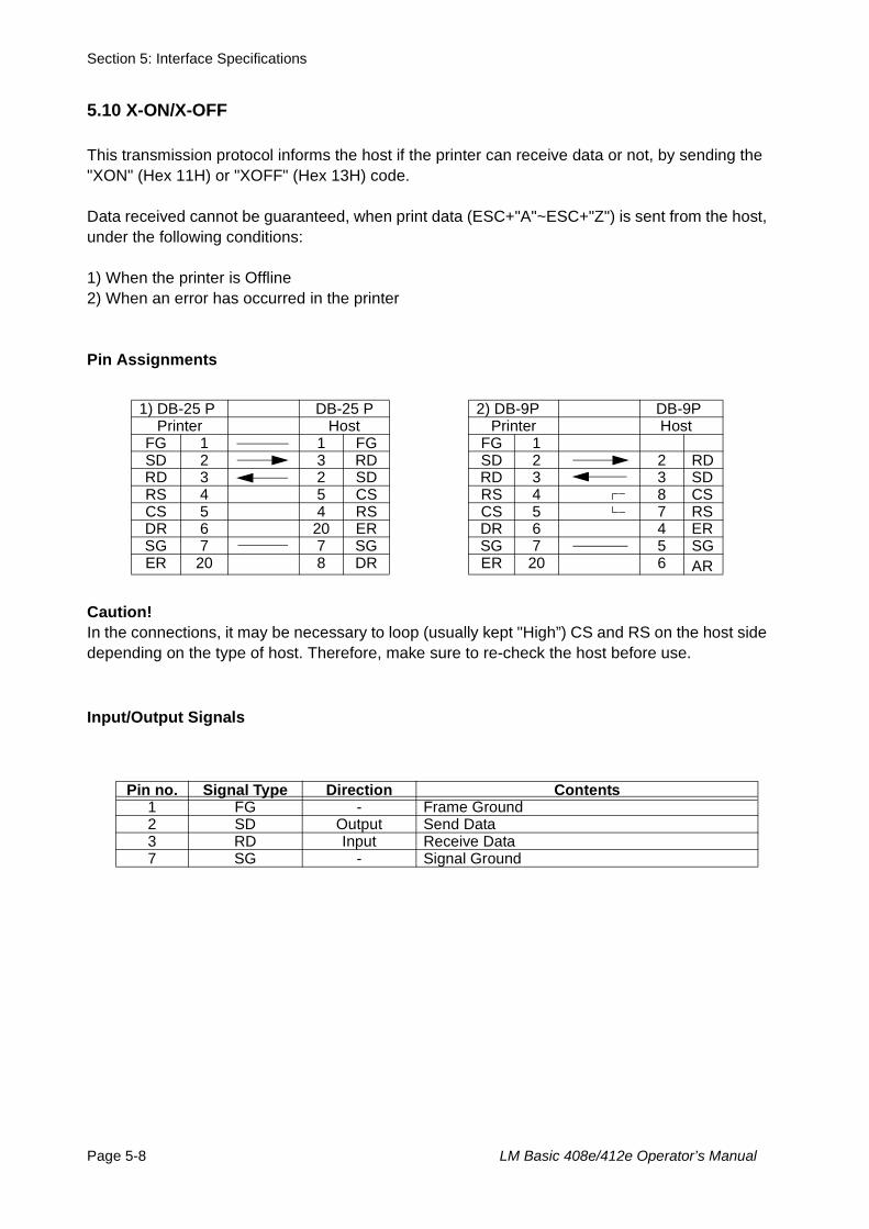
Section 5: Interface Specifications
Page 5-8 LM Basic 408e/412e Operator’s Manual
5.10 X-ON/X-OFF
This transmission protocol informs the host if the printer can receive data or not, by sending the "XON" (Hex 11H) or "XOFF" (Hex 13H) code.
Data received cannot be guaranteed, when print data (ESC+"A"~ESC+"Z") is sent from the host, under the following conditions:
1) When the printer is Offline2) When an error has occurred in the printer
Pin Assignments
Caution!In the connections, it may be necessary to loop (usually kept "High”) CS and RS on the host side depending on the type of host. Therefore, make sure to re-check the host before use.
Input/Output Signals
1) DB-25 P DB-25 P 2) DB-9P DB-9PPrinter Host Printer Host
FG 1 1 FG FG 1SD 2 3 RD SD 2 2 RDRD 3 2 SD RD 3 3 SDRS 4 5 CS RS 4 8 CSCS 5 4 RS CS 5 7 RSDR 6 20 ER DR 6 4 ERSG 7 7 SG SG 7 5 SGER 20 8 DR ER 20 6 AR
Pin no. Signal Type Direction Contents1 FG - Frame Ground2 SD Output Send Data3 RD Input Receive Data7 SG - Signal Ground
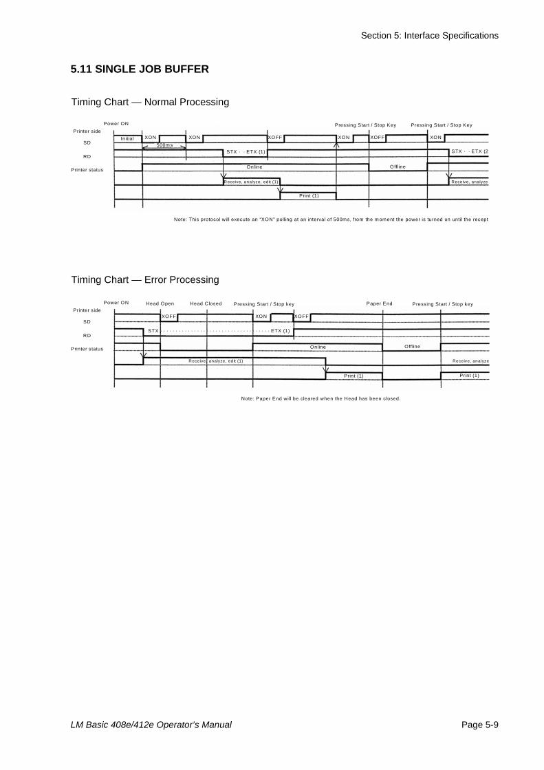
Section 5: Interface Specifications
LM Basic 408e/412e Operator’s Manual Page 5-9
5.11 SINGLE JOB BUFFER
Timing Chart — Normal Processing
Timing Chart — Error Processing
Power ON Printer side
SD
RD
Printer status
Initial
STX · · ETX (2
Online Offline
Receive, analyze, edit (1)
Print (1)
Note: This protocol will execute an “XON” polling at an interval of 500ms, from the moment the power is turned on until the recept
Pressing Start / Stop Key Pressing Start / Stop Key
STX · · ETX (1)
XON XON XOFF XON XON XOFF 500ms
Receive, analyze
Power ON Printer side
SD
RD
Printer status
Head Open
Online Offline
Receive, analyze, edit (1)
Print (1) Print (1)
Note: Paper End will be cleared when the Head has been closed.
Pressing Start / Stop key Pressing Start / Stop key
STX · · · · · · · · · · · · · · · · · · · · · · · · · · · · · · · · · · · · ETX (1)
XONXOFF XOFF
Receive, analyze
Head Closed Paper End
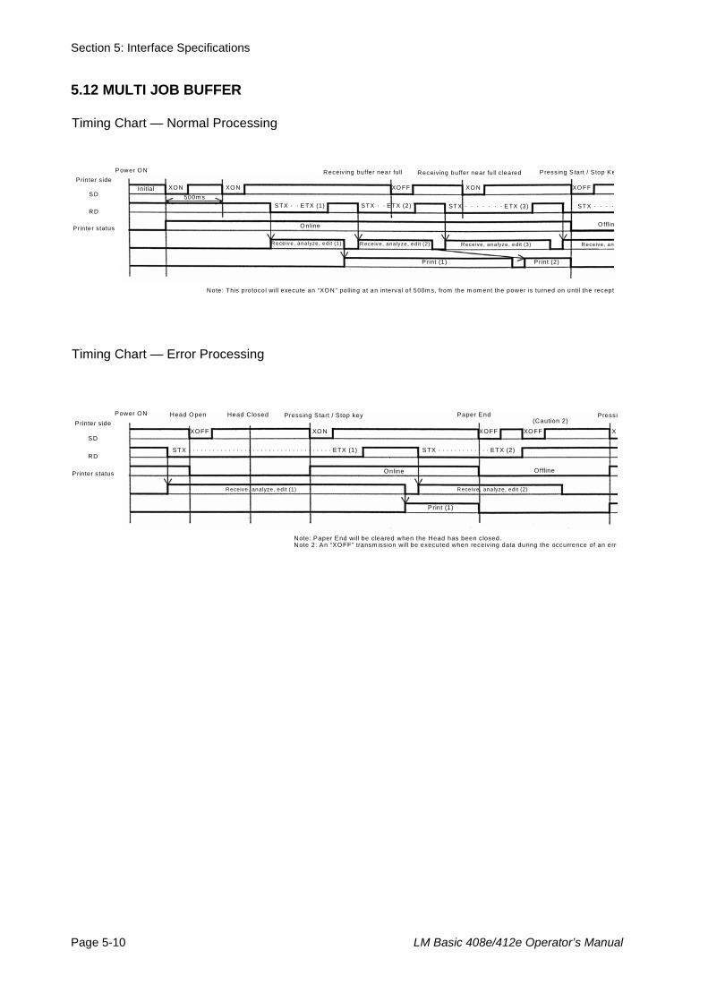
Section 5: Interface Specifications
Page 5-10 LM Basic 408e/412e Operator’s Manual
5.12 MULTI JOB BUFFER
Timing Chart — Normal Processing
Timing Chart — Error Processing
P ower O N Prin ter side
S D
RD
Prin ter status
Initia l
STX · · · · · · · E TX (3)
O nline O fflin
R eceive, analyze, edit (1)
P rint (1)
Note: This protocol will execute an “XO N” polling at an interva l o f 500m s, from the m om ent the power is turned on until the recept
Receiving buffer near fu ll P ress ing S tart / S top K e
S TX · · E TX (1)
XO N XO N XO NXO FF XO FF 500m s
Receive, an
Receiving buffer near fu ll c leared
STX · · E TX (2) S TX · · · ·
R eceive, analyze, edit (2) Receive, analyze, edit (3)
P rin t (2)
Power ON Printer side
SD
RD
Printer status
Head Open
Online Offline
Receive, analyze, edit (1)
Print (1)
Note: Paper End will be cleared when the Head has been closed. Note 2: An “XOFF” transm ission will be executed when receiving data during the occurrence of an erro
Pressing Start / Stop key Pressi
STX · · · · · · · · · · · · · · · · · · · · · · · · · · · · · · · · · · · · ETX (1)
XONXOFF XOFF
Receive, analyze, edit (2)
Head Closed Paper End
XOXOFF
(Caution 2)
STX · · · · · · · · · · · · · ETX (2)
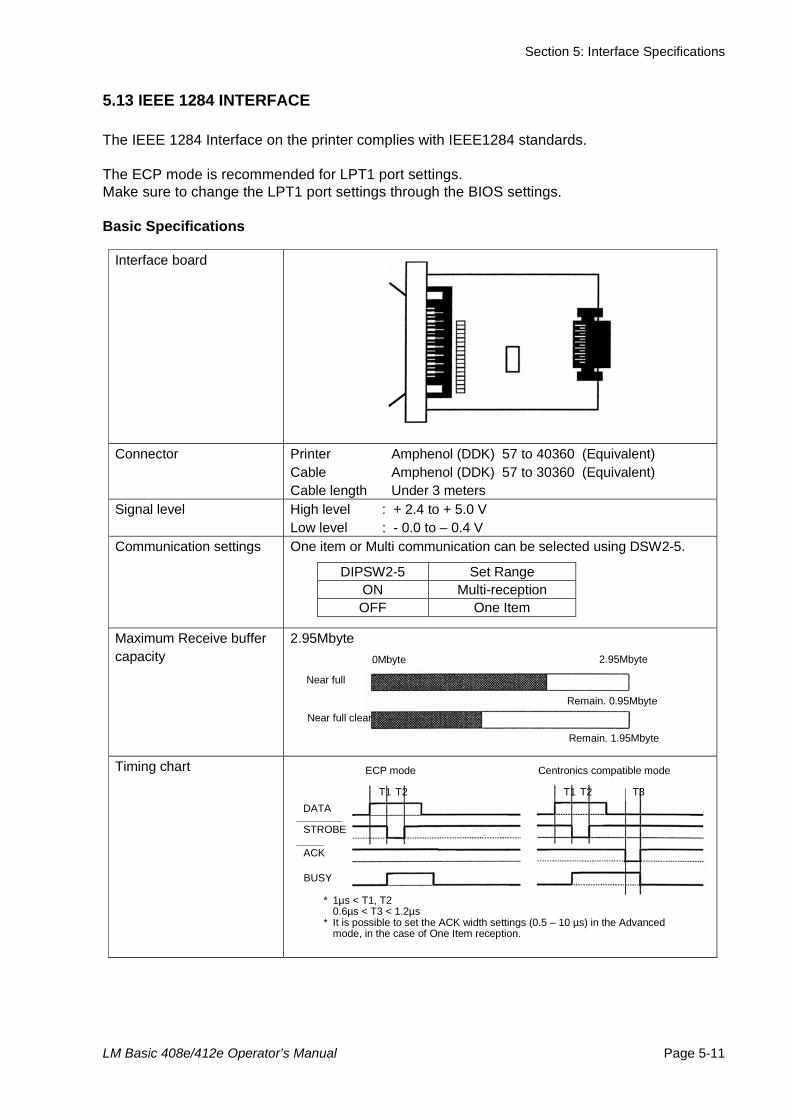
Section 5: Interface Specifications
LM Basic 408e/412e Operator’s Manual Page 5-11
5.13 IEEE 1284 INTERFACE
The IEEE 1284 Interface on the printer complies with IEEE1284 standards.
The ECP mode is recommended for LPT1 port settings.Make sure to change the LPT1 port settings through the BIOS settings.
Basic Specifications
Interface board
Connector Printer Amphenol (DDK) 57 to 40360 (Equivalent) Cable Amphenol (DDK) 57 to 30360 (Equivalent) Cable length Under 3 meters
Signal level High level : + 2.4 to + 5.0 V Low level : - 0.0 to – 0.4 V
Communication settings
One item or Multi communication can be selected using DSW2-5.
DIPSW2-5 Set Range ON Multi-reception OFF One Item
Maximum Receive buffer capacity
2.95Mbyte
Timing chart
0Mbyte 2.95Mbyte
Remain. 0.95Mbyte
Remain. 1.95Mbyte
Near full
Near full clear
DATA
STROBE
ACK
BUSY
* 1µs < T1, T2 0.6µs < T3 < 1.2µs * It is possible to set the ACK width settings (0.5 – 10 µs) in the Advanced
mode, in the case of One Item reception.
T1 T2
ECP mode Centronics compatible mode
T1 T2 T3
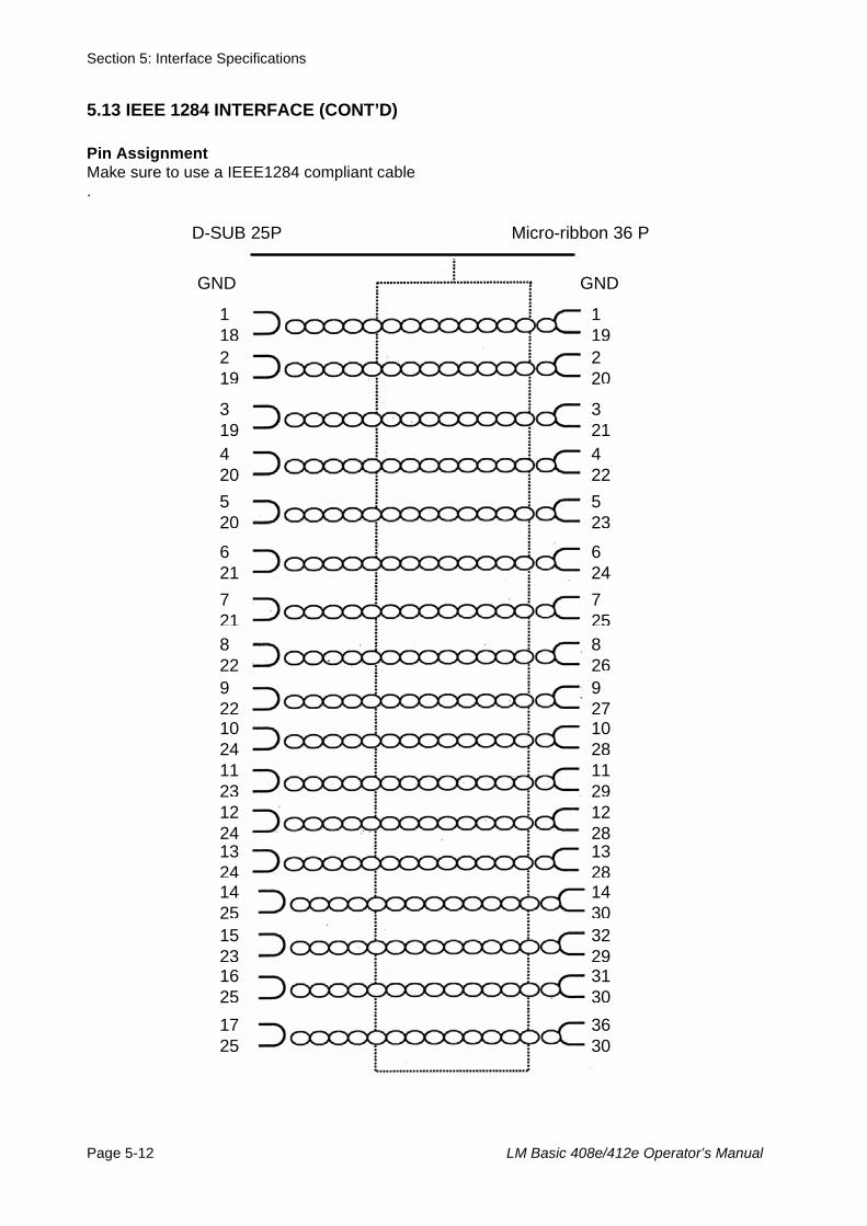
Section 5: Interface Specifications
Page 5-12 LM Basic 408e/412e Operator’s Manual
5.13 IEEE 1284 INTERFACE (CONT’D)
Pin AssignmentMake sure to use a IEEE1284 compliant cable.
GND
D-SUB 25P Micro-ribbon 36 P
GND
1 182 19
3 19 4 20 5 20
6 21 7 218 22 9 2210 24 11 23 12 24 13 2414 25 15 2316 25 17 25
1 192 20
3 214 225 23
6 247 258 269 2710 2811 2912 2813 2814 3032 2931 3036 30
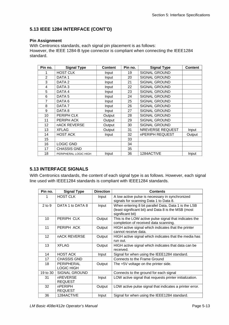
Section 5: Interface Specifications
LM Basic 408e/412e Operator’s Manual Page 5-13
5.13 IEEE 1284 INTERFACE (CONT’D)
Pin AssignmentWith Centronics standards, each signal pin placement is as follows:However, the IEEE 1284-B type connector is compliant when connecting the IEEE1284 standard.
5.13 INTERFACE SIGNALSWith Centronics standards, the content of each signal type is as follows. However, each signal line used with IEEE1284 standards is compliant with IEEE1284 standards.
Pin no. Signal Type Content Pin no. Signal Type Content
1 HOST CLK Input 19 SIGNAL GROUND 2 DATA 1 Input 20 SIGNAL GROUND 3 DATA 2 Input 21 SIGNAL GROUND 4 DATA 3 Input 22 SIGNAL GROUND 5 DATA 4 Input 23 SIGNAL GROUND 6 DATA 5 Input 24 SIGNAL GROUND 7 DATA 6 Input 25 SIGNAL GROUND 8 DATA 7 Input 26 SIGNAL GROUND 9 DATA 8 Input 27 SIGNAL GROUND
10 PERIPH CLK Output 28 SIGNAL GROUND 11 PERIPH ACK Output 29 SIGNAL GROUND 12 nACK REVERSE Output 30 SIGNAL GROUND 13 XFLAG Output 31 NREVERSE REQUEST Input 14 HOST ACK Input 32 nPERIPH REQUEST Output 15 33 16 LOGIC GND 34 17 CHASSIS GND 35 18 PERIPHERAL LOGIC HIGH Input 36 1284ACTIVE Input
Pin no. Signal Type Direction Contents
1 HOST CLK Input A low active pulse is necessary in synchronized signals for scanning Data 1 to Data 8.
2 to 9 DATA 1 to DATA 8 Input When entering 8 bit parallel Data, Data 1 is the LSB (least significant bit) and Data 8 is the MSB (most significant bit)
10 PERIPH CLK Output This is the LOW active pulse signal that indicates the completion of received data scanning.
11 PERIPH ACK Output HIGH active signal which indicates that the printer cannot receive data.
12 nACK REVERSE Output HIGH active signal which indicates that the media has run out.
13 XFLAG Output HIGH active signal which indicates that data can be received.
14 HOST ACK Input Signal for when using the IEEE1284 standard. 17 CHASSIS GND Connects to the Frame Ground 18 PERIPHERAL
LOGIC HIGH Output The +5V voltage on the printer side.
19 to 30 SIGNAL GROUND Connects to the ground for each signal 31 nREVERSE
REQUEST Input LOW active signal that requests printer initialization.
32 nPERIPH REQUEST
Output LOW active pulse signal that indicates a printer error.
36 1284ACTIVE Input Signal for when using the IEEE1284 standard.
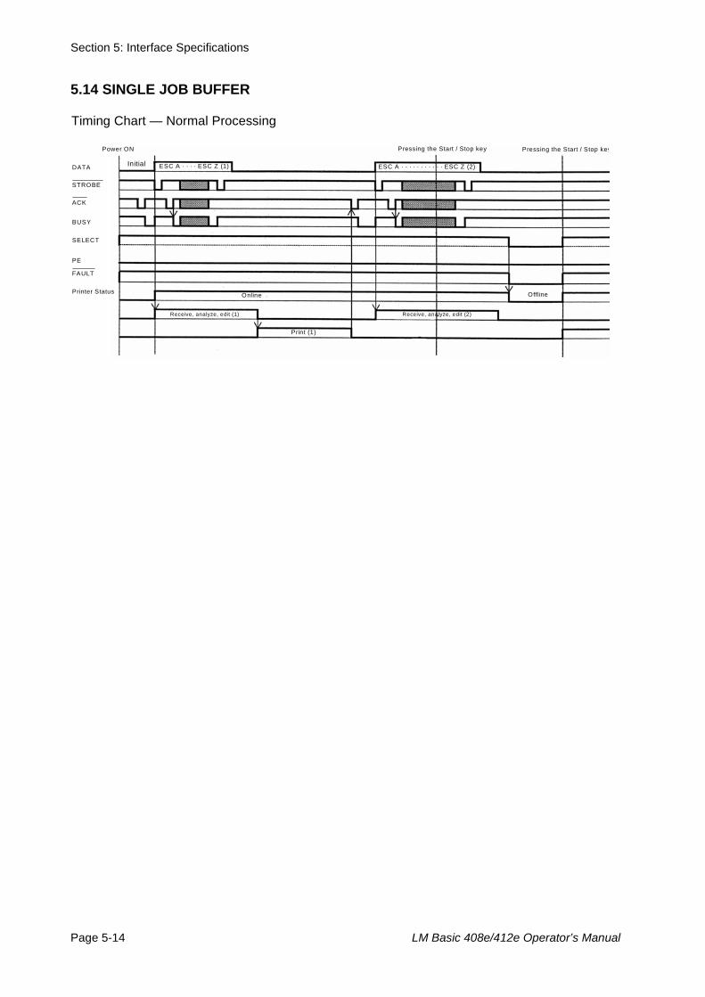
Section 5: Interface Specifications
Page 5-14 LM Basic 408e/412e Operator’s Manual
5.14 SINGLE JOB BUFFER
Timing Chart — Normal Processing
Power ON
Initial
Online
Receive, analyze, edit (1)
Print (1)
ESC A · · · · ESC Z (1)
Pressing the Start / Stop key Pressing the Start / Stop key
DATA
STROBE
ACK
BUSY
SELECT
PE
FAULT
Printer Status Offline
Receive, analyze, edit (2)
ESC A · · · · · · · · · · · ESC Z (2)
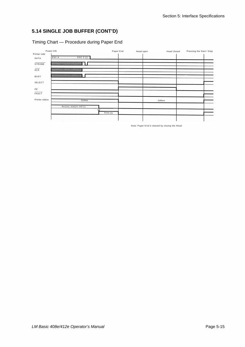
Section 5: Interface Specifications
LM Basic 408e/412e Operator’s Manual Page 5-15
5.14 SINGLE JOB BUFFER (CONT’D)
Timing Chart — Procedure during Paper End
Online
Receive, analyze, edit (1)
Print (1)
Pressing the Start / S top
ESC A · · · · · · · · · · ESC Z (1)
Paper End Head open Head closed
DATA
STROBE
ACK
BUSY
SELECT
PE
FAULT
Printer status O ffline
Note: Paper End is c leared by closing the Head.
Power O N Printer s ide
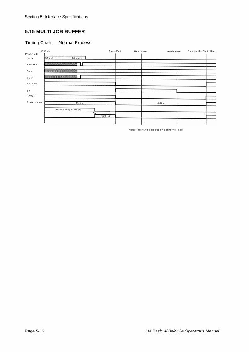
Section 5: Interface Specifications
Page 5-16 LM Basic 408e/412e Operator’s Manual
5.15 MULTI JOB BUFFER
Timing Chart — Normal Process
Online
Receive, analyze, edit (1)
Print (1)
P ressing the Start / S top
ESC A · · · · · · · · · · ESC Z (1)
Paper End Head open Head closed
DATA
STROBE
ACK
BUSY
SELECT
PE
FAULT
Printer status Offline
Note: Paper End is c leared by closing the Head.
Power ON Prin ter s ide
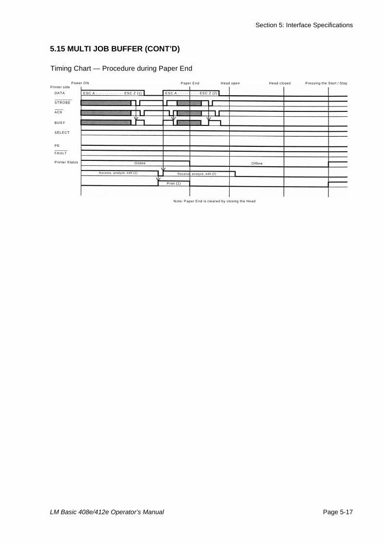
Section 5: Interface Specifications
LM Basic 408e/412e Operator’s Manual Page 5-17
5.15 MULTI JOB BUFFER (CONT’D)
Timing Chart — Procedure during Paper End
Power O N Printer s ide
O nline
Receive, analyze, edit (1)
Print (1)
ESC A · · · · · · · · · · · · · ESC Z (1)
Paper End Pressing the Start / Stop
DATA
STROBE
ACK
BUSY
SELECT
PE
FAULT
Printer Status Offline
Receive, analyze, edit (2)
ESC A · · · · · · · · · · ESC Z (2)
Head open Head closed
Note: Paper End is c leared by closing the Head

Section 5: Interface Specifications
Page 5-18 LM Basic 408e/412e Operator’s Manual
This page is intentionally left blank
Section 6: Troubleshooting
LM Basic 408e/412e Operator’s Manual Page 6-1
6TROUBLESHOOTING
If you are unable to produce printouts on the LM Series printer, use this section to make sure the basics have been checked, beforedeciding you are unable to proceed any further. The section is divided into seven parts:
• Initial Checklist• Checklist for the RS232C Serial Interface• Understanding ON LINE, RIBBON, LABEL indicators• Understanding the LCD error messages• Understanding the LCD warning messages• General Troubleshooting Guide
6.1 INITIAL CHECKLIST1. Is the printer powered up and ON LINE?
2. Is the ERROR light on the front panel OFF? If this light is ON, it may mean the print head assembly is open or another error condition is present.
3. Is the Print Head Assembly (as well as other related assembly that needs to be secured), in the latched position?
Observations
Section 6: Troubleshooting
Page 6-2 LM Basic 408e/412e Operator’s Manual
6.2 USING THE RS232C (SERIAL) INTERFACE
1. Is the RS232C Serial cable connected securely to your serial port on the PC and to the RS232C con-nector on the printer? (The standard SATO cable for RS-232 uses a 9 pin-female to a 25-pin male con-nector)
2. Is the cable defective? At the very least, you should be using a “Null Modem Cable,” which crosses pins in a specific manner. This should enable your printer to print. But we recommend that you eventually use a cable built to specifications as described in Sec-tion 5: Interface Specifications
3. Check for obvious errors in the data stream. Remember that all print jobs for serial data must be framed by an STX and ETX. Again, see the Section 5: Interface Specifications if necessary.
4. If after sending your job to the printer, the LCD indi-cates a “framing error” message, you may have a configuration problem. There may be some incon-sistencies with the Baud Rate, Parity, Data Bits, or Stop Bits in relation to your host computer. If you are confused as to what the printer’s current RS232 set-tings are, you may choose the SATO defaults (all DIP switches in the OFF position) to achieve 9600 baud, no parity, 8 data bits, and 1 stop bit.
Observations
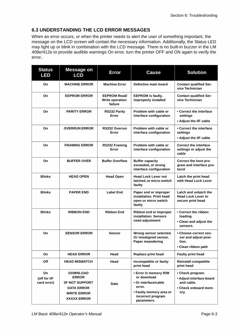
Section 6: Troubleshooting
LM Basic 408e/412e Operator’s Manual Page 6-3
6.3 UNDERSTANDING THE LCD ERROR MESSAGESWhen an error occurs, or when the printer needs to alert the user of something important, the message on the LCD screen will contain the necessary information. Additionally, the Status LED may light up or blink in combination with the LCD message. There is no built-in buzzer in the LM 408e/412e to provide audible warnings On error, turn the printer OFF and ON again to verify the error..
Status LED
Message on LCD Error Cause Solution
On MACHINE ERROR Machine Error Defective main board Contact qualified Ser-vice Technician
On EEPROM ERROR EEPROM Read/Write operation
failure
EEPROM is faulty, improperly installed
Contact qualified Ser-vice Technician
On PARITY ERROR RS232 Parity Error
Problem with cable or interface configuration
• Correct the interface settings
• Adjust the I/F cable
On OVERRUN ERROR RS232 Overrun Error
Problem with cable or interface configuration
• Correct the interface settings• Adjust the I/F cable
On FRAMING ERROR RS232 Framing Error
Problem with cable or interface configuration
Correct the interface settings or adjust the cable
On BUFFER OVER Buffer Overflow Buffer capacity exceeded, or wrong interface configuration
Correct the host pro-gram and interface pro-tocol
Blinks HEAD OPEN Head Open Head Lock Lever not latched, or micro-switch faulty
Latch the print head with Head Lock Lever
Blinks PAPER END Label End Paper end or improper installation. Print head open or micro switch faulty
Latch and unlatch the Head Lock Lever to secure print head
Blinks RIBBON END Ribbon End Ribbon end or improper installation. Sensors need adjustment
• Correct the ribbon loading.
• Clean and adjust the sensors.
On SENSOR ERROR Sensor Wrong sensor selected. Or misaligned sensor. Paper meandering
• Choose correct sen-sor and adjust posi-tion.
• Clean ribbon path
On HEAD ERROR Head Replace print head Faulty print head
Off HEAD MISMATCH Head Incompatible or faulty print head
Reinstall compatible print head
On (off for I/F card error)
DOWNLOAD ERROR
I/F NOT SUPPORTDATA ERROR
WRITE ERRORXXXXX ERROR
Data
• Error in memory R/W or download
• Or interface/cable error.
• Faulty memory area or incorrect program parameters.
• Check program. • Adjust interface board
and cable. • Check onboard mem-
ory.
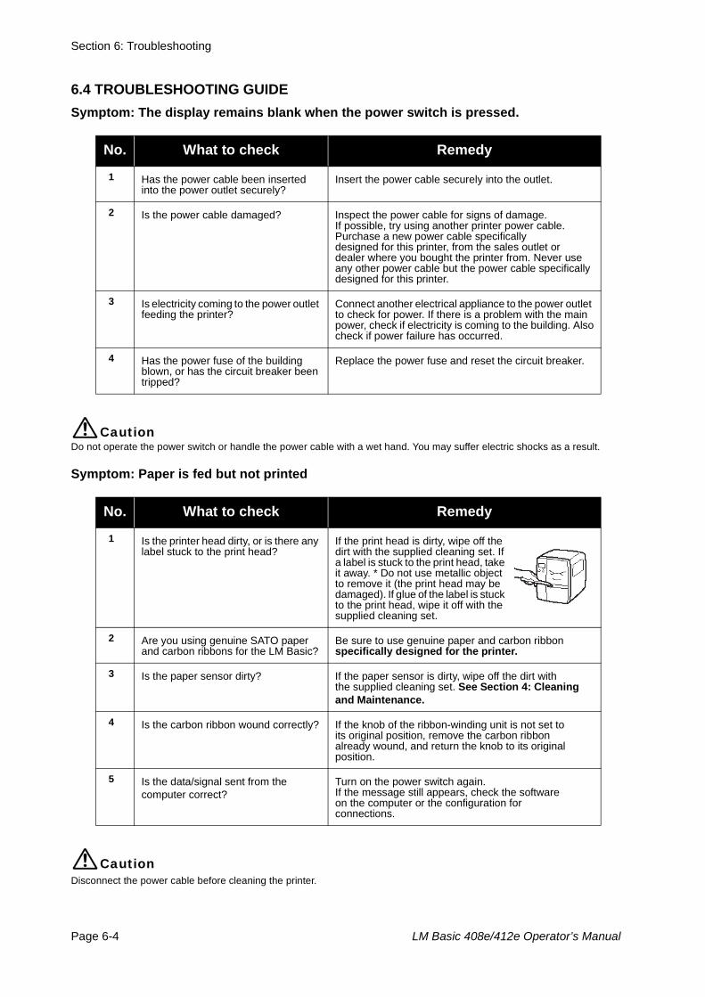
Section 6: Troubleshooting
Page 6-4 LM Basic 408e/412e Operator’s Manual
6.4 TROUBLESHOOTING GUIDESymptom: The display remains blank when the power switch is pressed.
CautionDo not operate the power switch or handle the power cable with a wet hand. You may suffer electric shocks as a result.
Symptom: Paper is fed but not printed
CautionDisconnect the power cable before cleaning the printer.
No. What to check Remedy
1 Has the power cable been inserted into the power outlet securely?
Insert the power cable securely into the outlet.
2 Is the power cable damaged? Inspect the power cable for signs of damage. If possible, try using another printer power cable.Purchase a new power cable specificallydesigned for this printer, from the sales outlet ordealer where you bought the printer from. Never use any other power cable but the power cable specifically designed for this printer.
3 Is electricity coming to the power outlet feeding the printer?
Connect another electrical appliance to the power outlet to check for power. If there is a problem with the main power, check if electricity is coming to the building. Alsocheck if power failure has occurred.
4 Has the power fuse of the building blown, or has the circuit breaker been tripped?
Replace the power fuse and reset the circuit breaker.
No. What to check Remedy
1 Is the printer head dirty, or is there any label stuck to the print head?
If the print head is dirty, wipe off the dirt with the supplied cleaning set. If a label is stuck to the print head, take it away. * Do not use metallic object to remove it (the print head may be damaged). If glue of the label is stuck to the print head, wipe it off with the supplied cleaning set.
2 Are you using genuine SATO paper and carbon ribbons for the LM Basic?
Be sure to use genuine paper and carbon ribbonspecifically designed for the printer.
3 Is the paper sensor dirty? If the paper sensor is dirty, wipe off the dirt withthe supplied cleaning set. See Section 4: Cleaning and Maintenance.
4 Is the carbon ribbon wound correctly? If the knob of the ribbon-winding unit is not set toits original position, remove the carbon ribbonalready wound, and return the knob to its originalposition.
5 Is the data/signal sent from the computer correct?
Turn on the power switch again.If the message still appears, check the softwareon the computer or the configuration forconnections.
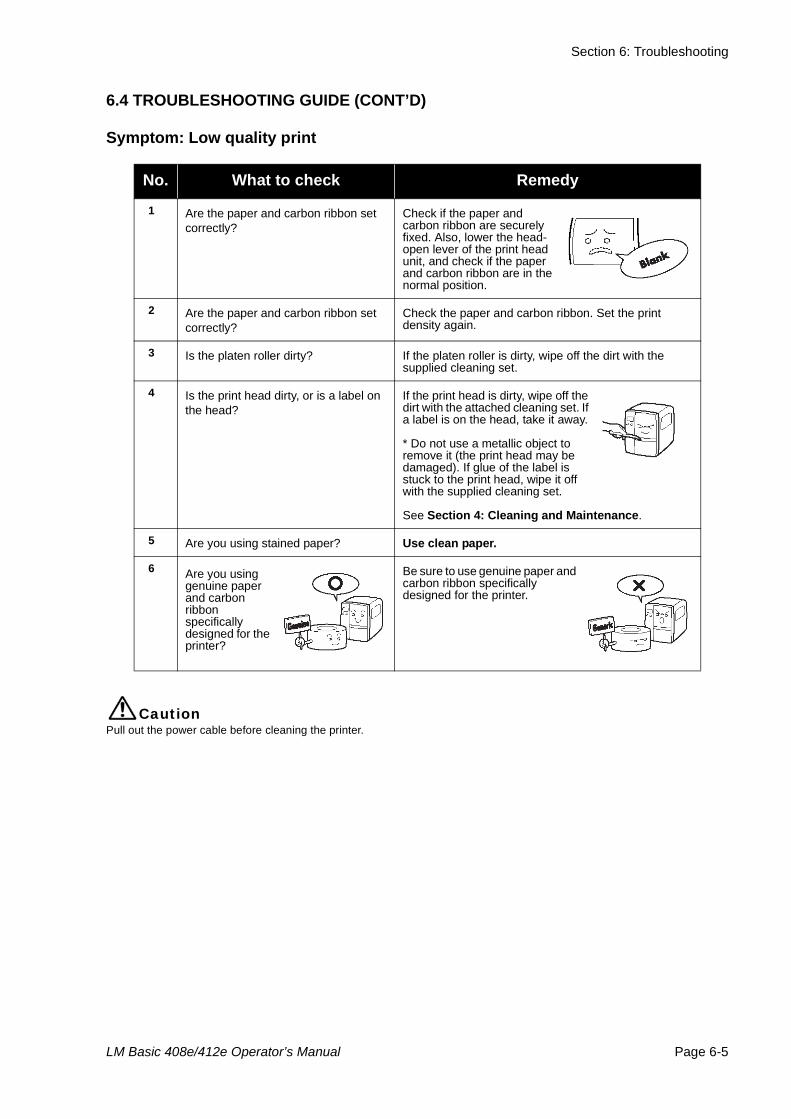
Section 6: Troubleshooting
LM Basic 408e/412e Operator’s Manual Page 6-5
6.4 TROUBLESHOOTING GUIDE (CONT’D)
Symptom: Low quality print
CautionPull out the power cable before cleaning the printer.
No. What to check Remedy
1 Are the paper and carbon ribbon set correctly?
Check if the paper and carbon ribbon are securely fixed. Also, lower the head-open lever of the print head unit, and check if the paper and carbon ribbon are in the normal position.
2 Are the paper and carbon ribbon set correctly?
Check the paper and carbon ribbon. Set the print density again.
3 Is the platen roller dirty? If the platen roller is dirty, wipe off the dirt with the supplied cleaning set.
4 Is the print head dirty, or is a label on the head?
If the print head is dirty, wipe off the dirt with the attached cleaning set. If a label is on the head, take it away.
* Do not use a metallic object to remove it (the print head may be damaged). If glue of the label is stuck to the print head, wipe it off with the supplied cleaning set.
See Section 4: Cleaning and Maintenance.
5 Are you using stained paper? Use clean paper.
6 Are you using genuine paper and carbon ribbon specifically designed for the printer?
Be sure to use genuine paper and carbon ribbon specifically designed for the printer.
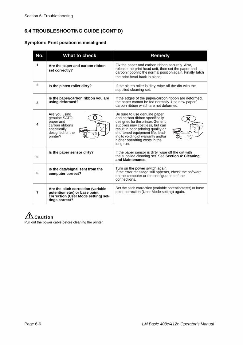
Section 6: Troubleshooting
Page 6-6 LM Basic 408e/412e Operator’s Manual
6.4 TROUBLESHOOTING GUIDE (CONT’D)
Symptom: Print position is misaligned
CautionPull out the power cable before cleaning the printer.
No. What to check Remedy
1 Are the paper and carbon ribbon set correctly?
Fix the paper and carbon ribbon securely. Also,release the print head unit, then set the paper and carbon ribbon to the normal position again. Finally, latch the print head back in place.
2 Is the platen roller dirty? If the platen roller is dirty, wipe off the dirt with thesupplied cleaning set.
3
Is the paper/carbon ribbon you are using deformed?
If the edges of the paper/carbon ribbon are deformed, the paper cannot be fed normally. Use new paper/carbon ribbon which are not deformed.
4
Are you using genuine SATO paper and carbon ribbons specifically designed for the printer?
Be sure to use genuine paper and carbon ribbon specifically designed for the printer. Generic supplies may cost less, but can result in poor printing quality or shortened equipment life, lead-ing to voiding of warranty and/or higher operating costs in the long run.
5
Is the paper sensor dirty? If the paper sensor is dirty, wipe off the dirt withthe supplied cleaning set. See Section 4: Cleaning and Maintenance.
6
Is the data/signal sent from the computer correct?
Turn on the power switch again.If the error message still appears, check the softwareon the computer or the configuration of theconnections.
7
Are the pitch correction (variable potentiometer) or base point correction (User Mode setting) set-tings correct?
Set the pitch correction (variable potentiometer) or base point correction (User Mode setting) again.
Section 7: Optional Accessories
LM Basic 408e/412e Operator’s Manual Page 7-1
7OPTIONAL ACCESSORIES
7.1 INTRODUCTIONThis section contains details of the optional accessories available for the LM printer:
• Interface boards• Calendar IC
7.2 AVAILABLE INTERFACE BOARDSInterface boards enable the printer to exchange data with computers, computer networks and related input/output devices. By installing a different interface board, you can adapt the LM printer to fit in a wide range of related equipment and usage scenarios.
At the time of purchase, the LM printer includes ONE interface board of your choice, from the fol-lowing interface boards available:
¤ Serial interface board (RS-232C)¤ IEEE 1284 Parallel interface board¤ High Speed RS-232C¤ USB 1.1 interface board¤ 10BaseT/100Base-TX LAN interface board ¤ Wireless LAN IEEE802.11b interface board
CautionBefore installing or removing interface boards, be sure to turn off the printer first. Discharge static electricity from your body before touching any of the electronic parts. Failure to observe these precautions can result in severe damage to the components.
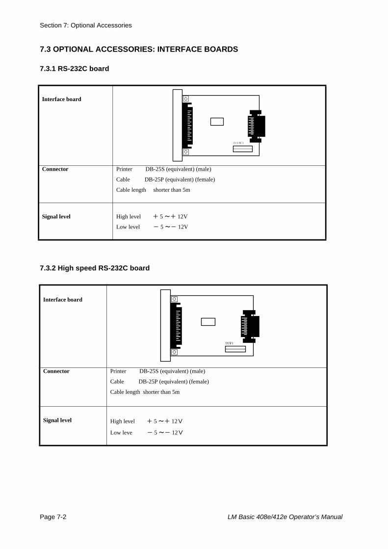
Section 7: Optional Accessories
Page 7-2 LM Basic 408e/412e Operator’s Manual
7.3 OPTIONAL ACCESSORIES: INTERFACE BOARDS
7.3.1 RS-232C board
7.3.2 High speed RS-232C board
Interface board
Connector Printer DB-25S (equivalent) (male)
Cable DB-25P (equivalent) (female)
Cable length shorter than 5m
Signal level High level + 5 ~+ 12V
Low level - 5 ~- 12V
Interface board
Connector Printer DB-25S (equivalent) (male)
Cable DB-25P (equivalent) (female)
Cable length shorter than 5m
Signal level High level + 5 ~+ 12V
Low leve - 5 ~- 12V
DSW1
DSW1
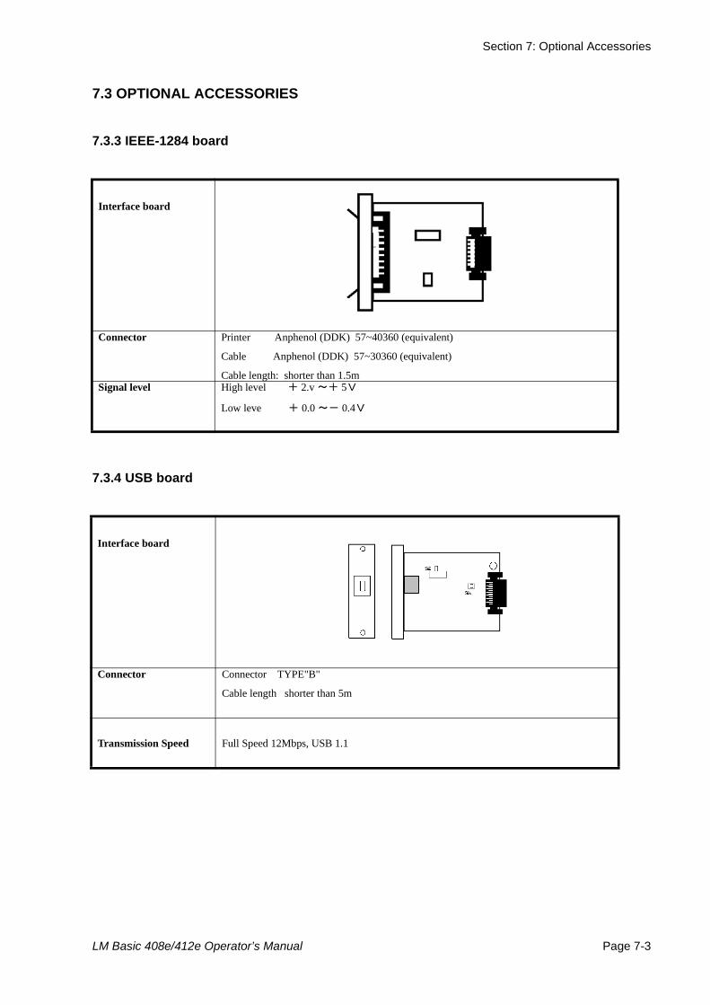
Section 7: Optional Accessories
LM Basic 408e/412e Operator’s Manual Page 7-3
7.3 OPTIONAL ACCESSORIES
7.3.3 IEEE-1284 board
7.3.4 USB board
Interface board
Connector Printer Anphenol (DDK) 57~40360 (equivalent)
Cable Anphenol (DDK) 57~30360 (equivalent)
Cable length: shorter than 1.5mSignal level High level + 2.v ~+ 5V
Low leve + 0.0 ~- 0.4V
Interface board
Connector Connector TYPE"B"
Cable length shorter than 5m
Transmission Speed Full Speed 12Mbps, USB 1.1
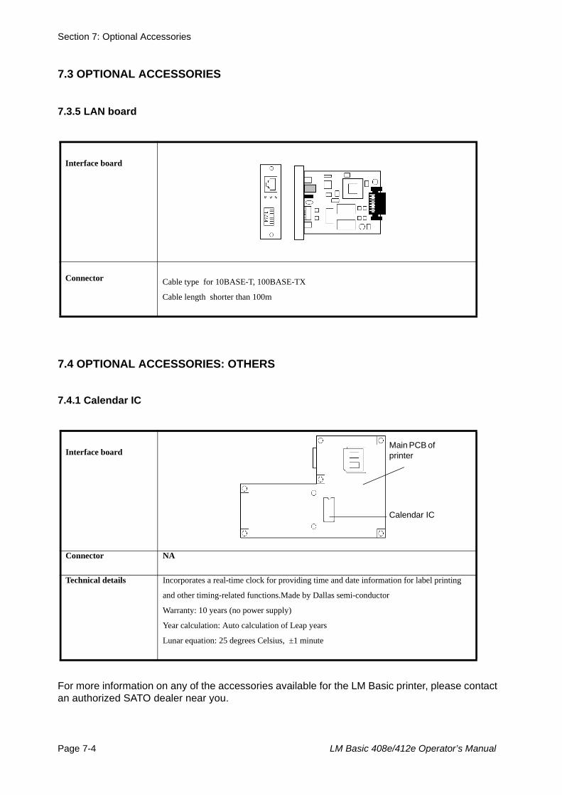
Section 7: Optional Accessories
Page 7-4 LM Basic 408e/412e Operator’s Manual
For more information on any of the accessories available for the LM Basic printer, please contact an authorized SATO dealer near you.
7.3 OPTIONAL ACCESSORIES
7.3.5 LAN board
7.4 OPTIONAL ACCESSORIES: OTHERS
7.4.1 Calendar IC
Interface board
Connector Cable type for 10BASE-T, 100BASE-TX
Cable length shorter than 100m
Interface board
Connector NA
Technical details Incorporates a real-time clock for providing time and date information for label printing
and other timing-related functions.Made by Dallas semi-conductor
Warranty: 10 years (no power supply)
Year calculation: Auto calculation of Leap years
Lunar equation: 25 degrees Celsius, ±1 minute
Calendar IC
Main PCB of printer


