41
LME –Environmental Effects & Coatings Branch Craig Robinson March 28, 2017 https://ntrs.nasa.gov/search.jsp?R=20170005558 2018-07-10T12:38:07+00:00Z
LME –Environmental Effects & Coatings
Branch
Craig Robinson
March 28, 2017
https://ntrs.nasa.gov/search.jsp?R=20170005558 2018-07-10T12:38:07+00:00Z
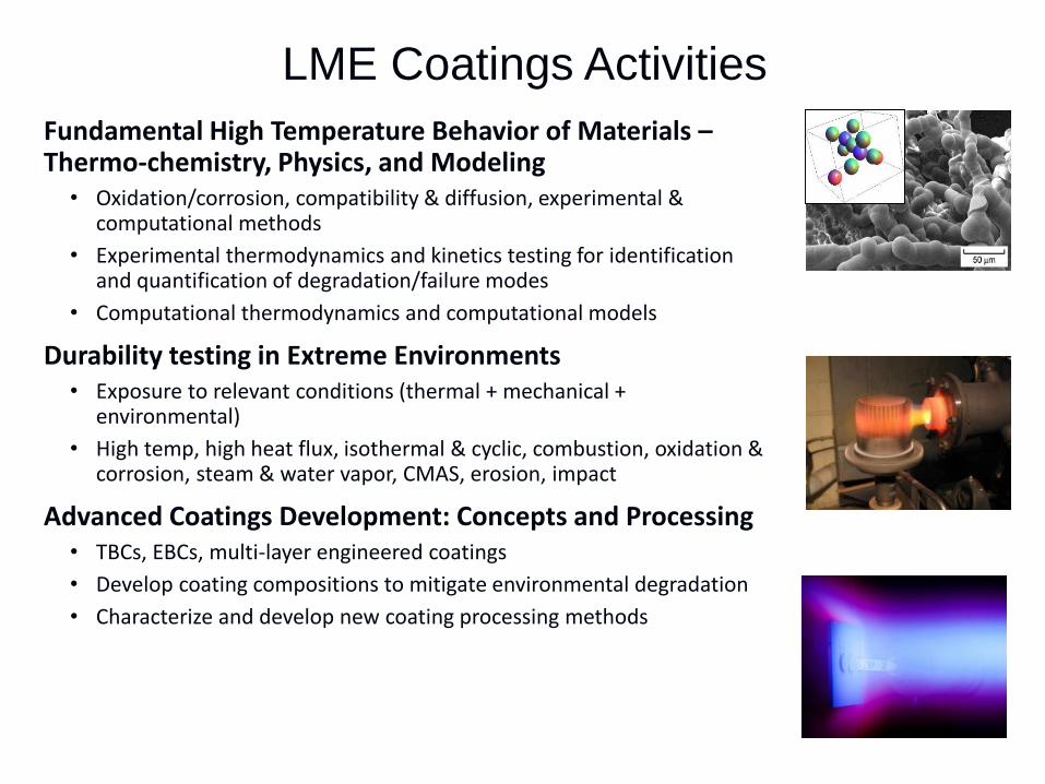
LME Coatings Activities
Fundamental High Temperature Behavior of Materials –Thermo-chemistry, Physics, and Modeling
• Oxidation/corrosion, compatibility & diffusion, experimental & computational methods
• Experimental thermodynamics and kinetics testing for identification and quantification of degradation/failure modes
• Computational thermodynamics and computational models
Durability testing in Extreme Environments• Exposure to relevant conditions (thermal + mechanical +
environmental)
• High temp, high heat flux, isothermal & cyclic, combustion, oxidation & corrosion, steam & water vapor, CMAS, erosion, impact
Advanced Coatings Development: Concepts and Processing• TBCs, EBCs, multi-layer engineered coatings
• Develop coating compositions to mitigate environmental degradation
• Characterize and develop new coating processing methods

Outline
• EBCs• Thermo-chemistry & Modeling efforts
• Environmental Durability testing capabilities and current efforts
• Processing
• TBCs
• Challenges & Potential Collaborations

EBCs
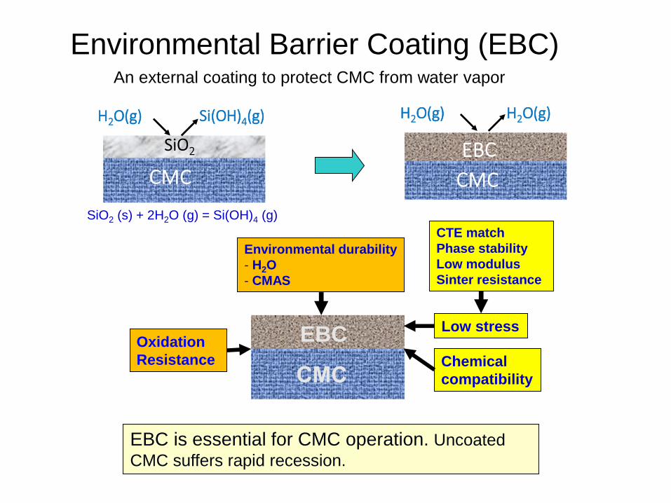
Environmental Barrier Coating (EBC)An external coating to protect CMC from water vapor
H2O(g) Si(OH)4(g) H2O(g) H2O(g)
SiO2 (s) + 2H2O (g) = Si(OH)4 (g)
EBCChemical
compatibility
Low stressOxidation
Resistance
Environmental durability
- H2O
- CMAS
CTE match
Phase stability
Low modulus
Sinter resistance
EBC is essential for CMC operation. Uncoated
CMC suffers rapid recession.

National Aeronautics and Space Administration
www.nasa.gov
NASA EBC History• 1990’s: Gen 1.0
– Silicon Bond coat
– Mullite (3Al2O3-2SiO2) / Mullite + BSAS
intermediate layer
– BSAS (BaO/SrO/Al2O3/SiO2) Topcoat
• 2000’s: Gen 2.0
– Silicon Bondcoat
– Rare earth (RE) silicate topcoat (e.g. Yb2Si2O7)
– RE silicates improve H2O resistance
• 2010’s: Next Generation EBCs
– 2700oF capable bond coat
• HfO2+Si & RESi Bond coat
• Oxide-based bond coat
– CMAS mitigation
– Novel EBC processes
• DVD
• PS-PVD
• Slurry
6
Si
Yb2Si2O7
(Gd/Y)Yb2Si2O7
HfO2-Si
SiC/SiC CMC
BSASMullite / Mullite + BSAS
SiC

Thermo-chem & Modeling

Thermo-chemistry & Modeling
GRC identified Si(OH)4 product for reaction of SiC
with moisture – reaction is life limiting to SiC/SiC
durability in turbine engines
Experimental Thermodynamics & Kinetics Capabilities:
• Identify gaseous reaction products
• Determine kinetic rates
Knudsen Effusion
Mass Spectrometer
Thermo-gravimetric
Analysis (air/water/vacuum)
Computational Thermodynamics & Computational Models:
• Thermodynamics & kinetic approach• Identify degradation modes due to adverse reactions w/ adjoining
materials and environment constituents
• Code generated phase diagrams (FactSage / ThermoCalc / Dictra)
• Modeling efforts complimented with in-house experimental capabilities
• Atomistic, nanoscale, and continuum DFT materials modeling• Molecular dynamics, Metropolis/Kinetic Monte Carlo, and particle
statics/dynamics Oxygen Diffusivity in ZrO2
SiO2 (s) + 2H2O (g) = Si(OH)4 (g)
Boundary Layer Vapor Flux α a(SiO2)• Kp

National Aeronautics and Space Administration
www.nasa.gov
Solid Phase Thermodynamics
• Measured thermodynamic activity of SiO2, a(SiO2) in
– Y2O3-SiO2, Yb2O3-SiO2, Lu2O3-SiO2 (in progress)…looking for trends
– Use Knudsen Effusion Mass Spectrometry (KEMS)
9
• Measure ion intensity
of species in vapor
• These relate to
activity in the solid
National Aeronautics and Space Administration
www.nasa.gov
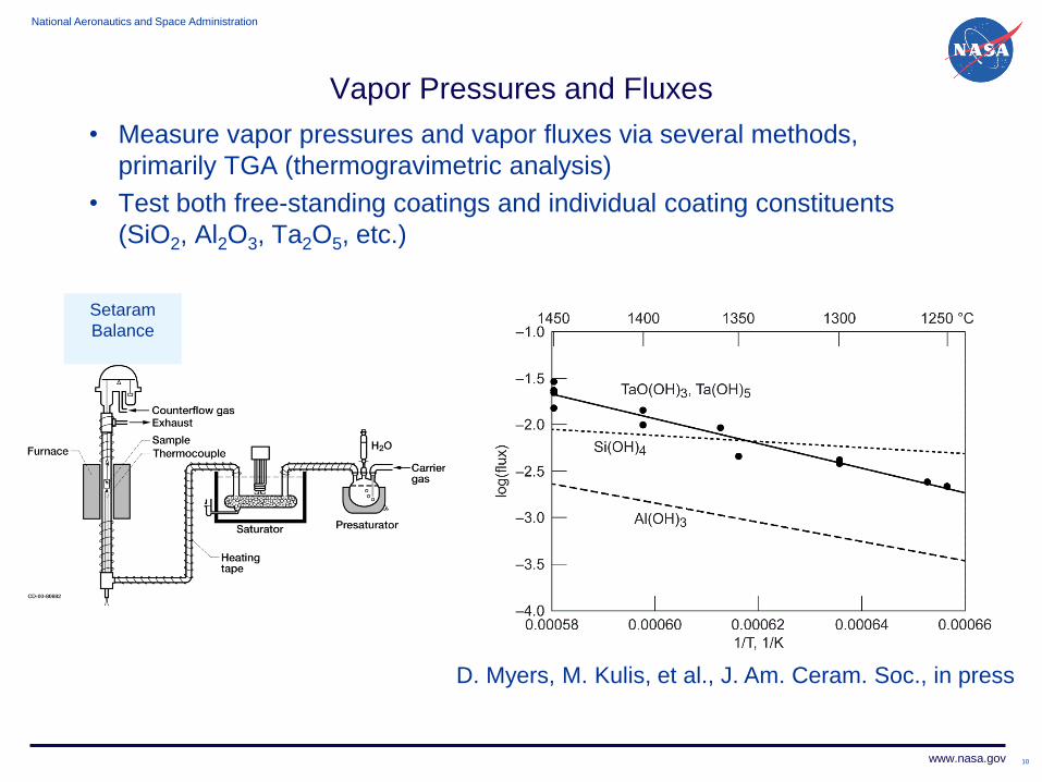
Vapor Pressures and Fluxes
• Measure vapor pressures and vapor fluxes via several methods,
primarily TGA (thermogravimetric analysis)
• Test both free-standing coatings and individual coating constituents
(SiO2, Al2O3, Ta2O5, etc.)
10
Setaram
Balance
D. Myers, M. Kulis, et al., J. Am. Ceram. Soc., in press
National Aeronautics and Space Administration
www.nasa.gov
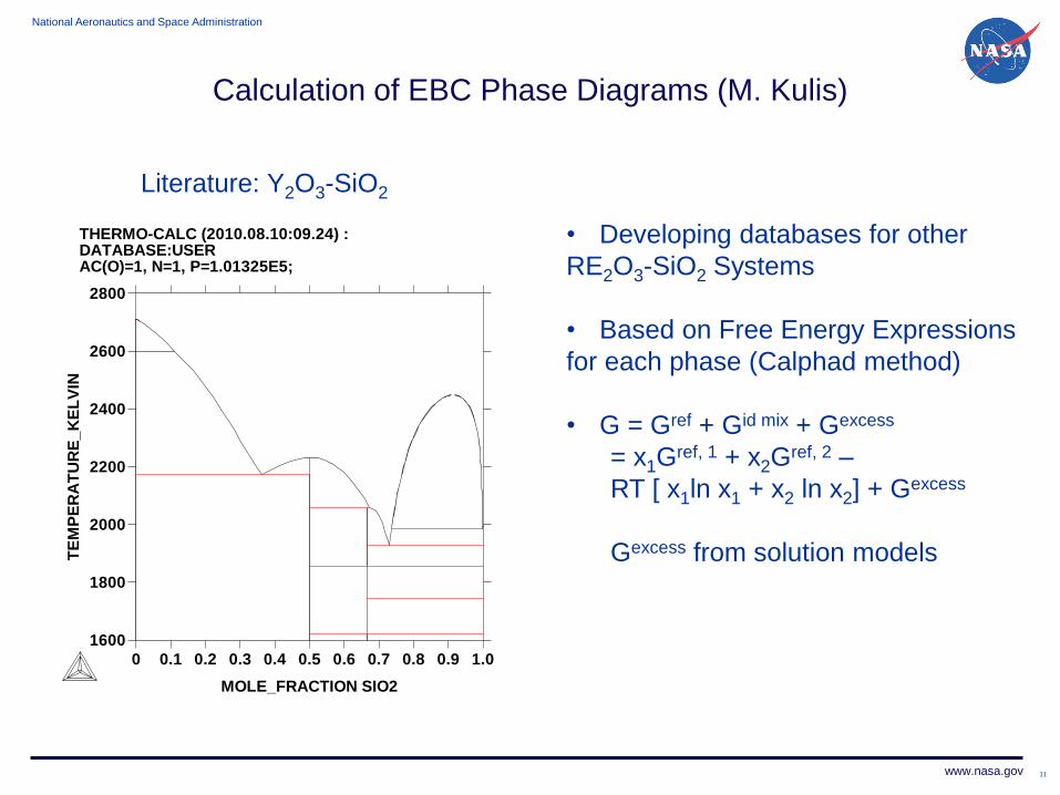
Calculation of EBC Phase Diagrams (M. Kulis)
11
1600
1800
2000
2200
2400
2600
2800
TE
MP
ER
AT
UR
E_
KE
LV
IN
0 0.1 0.2 0.3 0.4 0.5 0.6 0.7 0.8 0.9 1.0
MOLE_FRACTION SIO2
THERMO-CALC (2010.08.10:09.24) : DATABASE:USER AC(O)=1, N=1, P=1.01325E5;
Literature: Y2O3-SiO2
• Developing databases for other
RE2O3-SiO2 Systems
• Based on Free Energy Expressions
for each phase (Calphad method)
• G = Gref + Gid mix + Gexcess
= x1Gref, 1 + x2G
ref, 2 –
RT [ x1ln x1 + x2 ln x2] + Gexcess
Gexcess from solution models
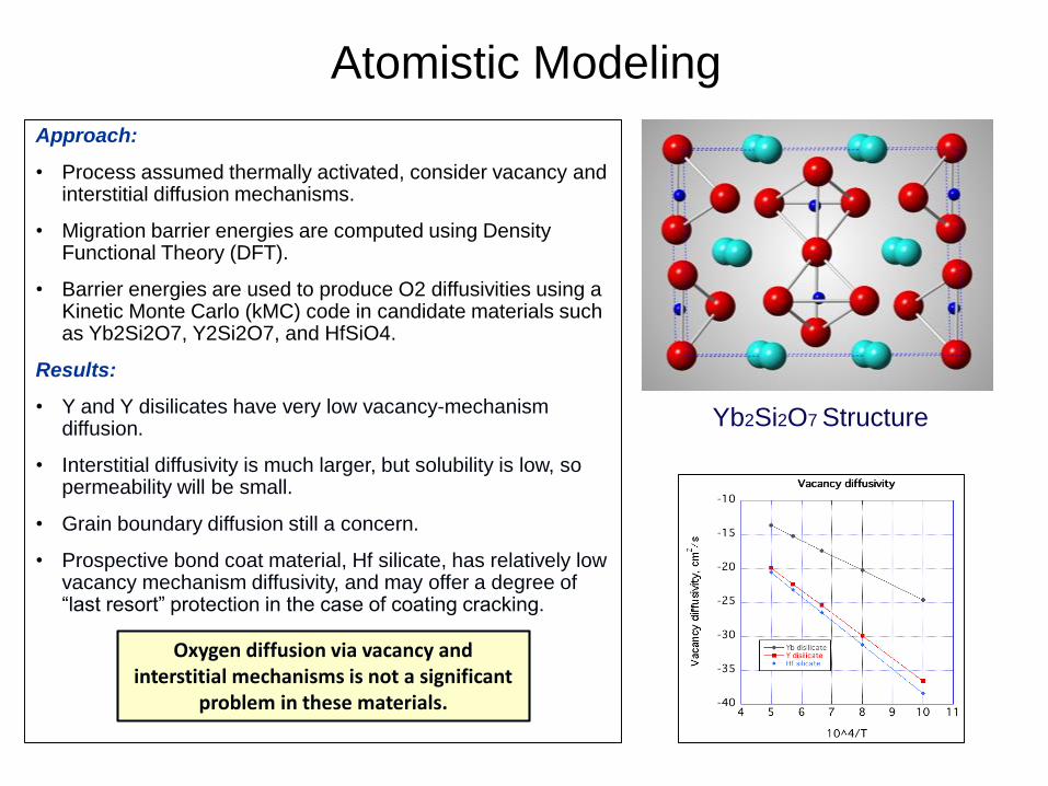
Atomistic Modeling
Approach:
• Process assumed thermally activated, consider vacancy and interstitial diffusion mechanisms.
• Migration barrier energies are computed using Density Functional Theory (DFT).
• Barrier energies are used to produce O2 diffusivities using a Kinetic Monte Carlo (kMC) code in candidate materials such as Yb2Si2O7, Y2Si2O7, and HfSiO4.
Results:
• Y and Y disilicates have very low vacancy-mechanism diffusion.
• Interstitial diffusivity is much larger, but solubility is low, so permeability will be small.
• Grain boundary diffusion still a concern.
• Prospective bond coat material, Hf silicate, has relatively low vacancy mechanism diffusivity, and may offer a degree of “last resort” protection in the case of coating cracking.
Yb2Si2O7 Structure
Oxygen diffusion via vacancy and interstitial mechanisms is not a significant
problem in these materials.
Extreme Environments Testing
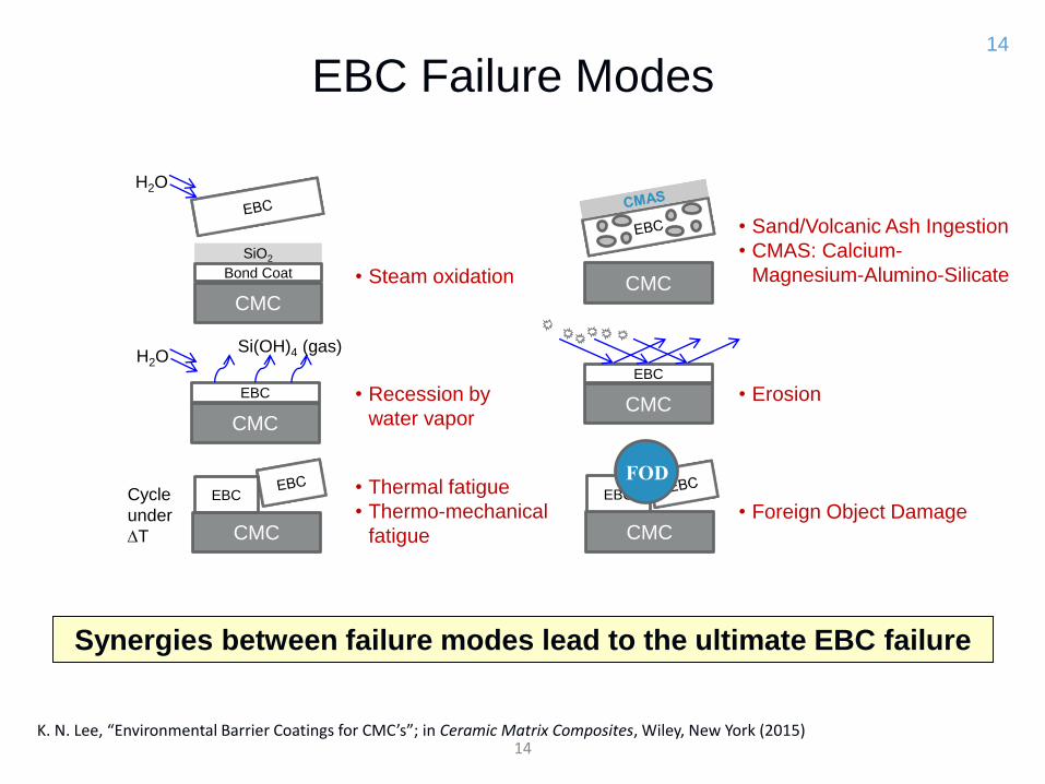
EBC Failure Modes14
K. N. Lee, “Environmental Barrier Coatings for CMC’s”; in Ceramic Matrix Composites, Wiley, New York (2015)
Synergies between failure modes lead to the ultimate EBC failure
CMC
SiO2
CMC
EBC
EBC
CMC
CMC
EBC
CMC
• Steam oxidation
• Recession by
water vapor
• Thermal fatigue
• Thermo-mechanical
fatigue
• Sand/Volcanic Ash Ingestion
• CMAS: Calcium-
Magnesium-Alumino-Silicate
• Erosion
• Foreign Object Damage
Bond Coat
H2O
Cycle
under
DT
H2O
Si(OH)4 (gas)
CMC
EBC
FOD
14
Title - Arial 28pt
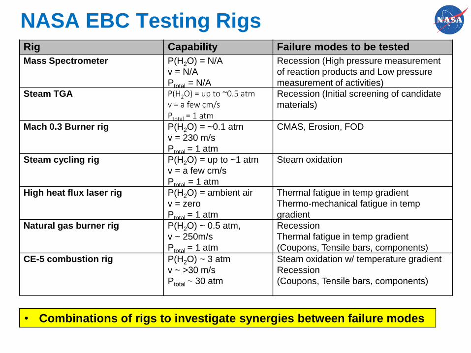
Rig Capability Failure modes to be tested
Mass Spectrometer P(H2O) = N/A
v = N/A
Ptotal = N/A
Recession (High pressure measurement
of reaction products and Low pressure
measurement of activities)
Steam TGA P(H2O) = up to ~0.5 atm v = a few cm/sPtotal = 1 atm
Recession (Initial screening of candidate
materials)
Mach 0.3 Burner rig P(H2O) = ~0.1 atm
v = 230 m/s
Ptotal = 1 atm
CMAS, Erosion, FOD
Steam cycling rig P(H2O) = up to ~1 atm
v = a few cm/s
Ptotal = 1 atm
Steam oxidation
High heat flux laser rig P(H2O) = ambient air
v = zero
Ptotal = 1 atm
Thermal fatigue in temp gradient
Thermo-mechanical fatigue in temp
gradient
Natural gas burner rig P(H2O) ~ 0.5 atm,
v ~ 250m/s
Ptotal = 1 atm
Recession
Thermal fatigue in temp gradient
(Coupons, Tensile bars, components)
CE-5 combustion rig P(H2O) ~ 3 atm
v ~ >30 m/s
Ptotal ~ 30 atm
Steam oxidation w/ temperature gradient
Recession
(Coupons, Tensile bars, components)
NASA EBC Testing Rigs
• Combinations of rigs to investigate synergies between failure modes
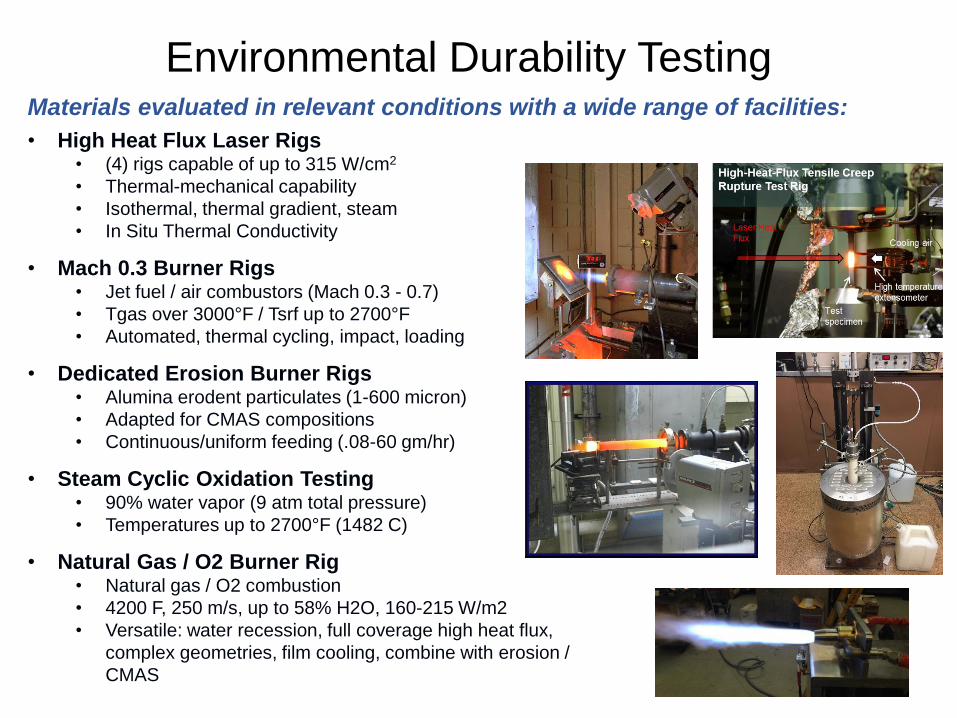
Environmental Durability TestingMaterials evaluated in relevant conditions with a wide range of facilities:
• High Heat Flux Laser Rigs• (4) rigs capable of up to 315 W/cm2
• Thermal-mechanical capability
• Isothermal, thermal gradient, steam
• In Situ Thermal Conductivity
• Mach 0.3 Burner Rigs• Jet fuel / air combustors (Mach 0.3 - 0.7)
• Tgas over 3000°F / Tsrf up to 2700°F
• Automated, thermal cycling, impact, loading
• Dedicated Erosion Burner Rigs• Alumina erodent particulates (1-600 micron)
• Adapted for CMAS compositions
• Continuous/uniform feeding (.08-60 gm/hr)
• Steam Cyclic Oxidation Testing• 90% water vapor (9 atm total pressure)
• Temperatures up to 2700°F (1482 C)
• Natural Gas / O2 Burner Rig• Natural gas / O2 combustion
• 4200 F, 250 m/s, up to 58% H2O, 160-215 W/m2
• Versatile: water recession, full coverage high heat flux,
complex geometries, film cooling, combine with erosion /
CMAS

- Silicon oxidizes faster in H2O(g) than in air by an order of magnitude- Attributed to high solubility of H2O(g) in SiO2
- Ceramic top coat does not stop the transport of H2O(g) to Si bond coat
First Gen EBC0.9 atm pH2O + 0.1 am O2
GE Final Report – AMAIGT Program Dec. 2010
SiO2
Silicon0.9 atm pH2O + 0.1 am O2
SiliconO2 = 0.1 atm
H2O(g) Si(OH)4(g)
H2O (g)
Silicon Bond coat
Isothermal Oxidation, T = 2200oF (1204oC)
Oxidation of EBC/CMC system must be evaluated in H2O environments
Cyclic Oxidation, 2400oF, 90% H2O
Gen 2, 100h, TGO 6~7 mm
SiO2
Si
Yb2Si2O7
NASA, Unpublished data
EBC Steam Oxidation
PS-PVD YbDS EBC on hexoloy substrate
18
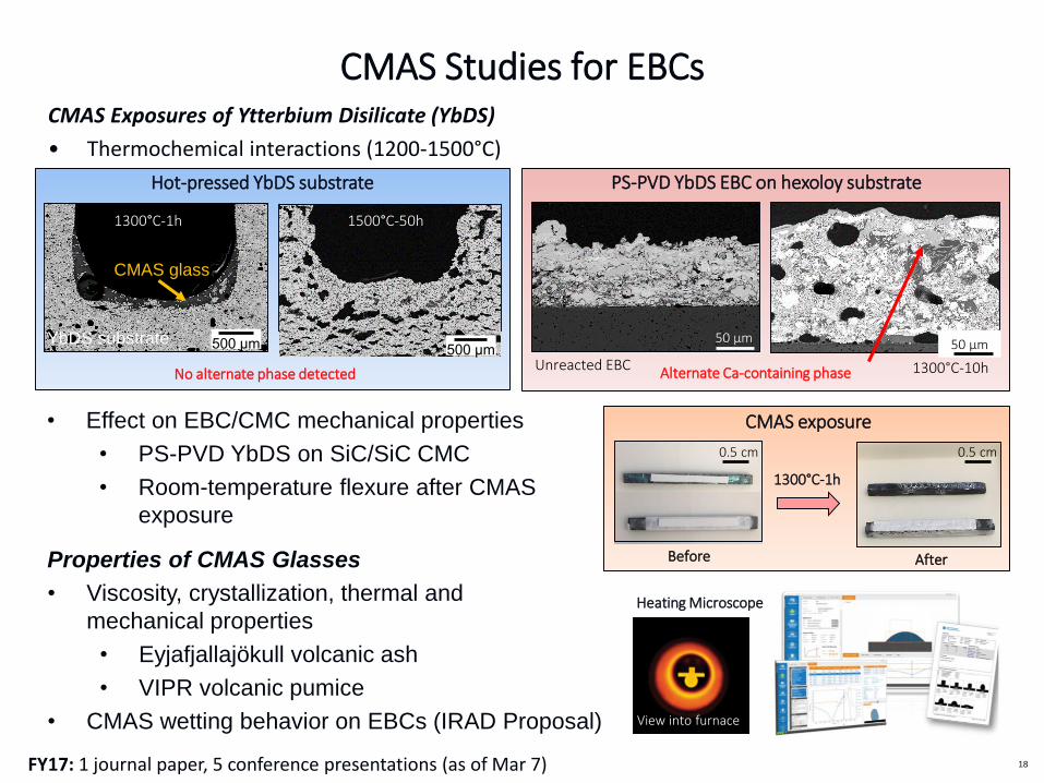
CMAS Exposures of Ytterbium Disilicate (YbDS)
• Thermochemical interactions (1200-1500°C)
CMAS Studies for EBCs
FY17: 1 journal paper, 5 conference presentations (as of Mar 7)
500 μm
Properties of CMAS Glasses
• Viscosity, crystallization, thermal and
mechanical properties
• Eyjafjallajökull volcanic ash
• VIPR volcanic pumice
• CMAS wetting behavior on EBCs (IRAD Proposal)
Hot-pressed YbDS substrate
500 μm
No alternate phase detected
CMAS glass
50 µm
Unreacted EBC
1300°C-1h 1500°C-50h
50 µm
1300°C-10h
• Effect on EBC/CMC mechanical properties
• PS-PVD YbDS on SiC/SiC CMC
• Room-temperature flexure after CMAS
exposure
Alternate Ca-containing phase
View into furnace
Heating Microscope
0.5 cm
1300°C-1h
Before After
0.5 cm
CMAS exposure
YbDS substrate
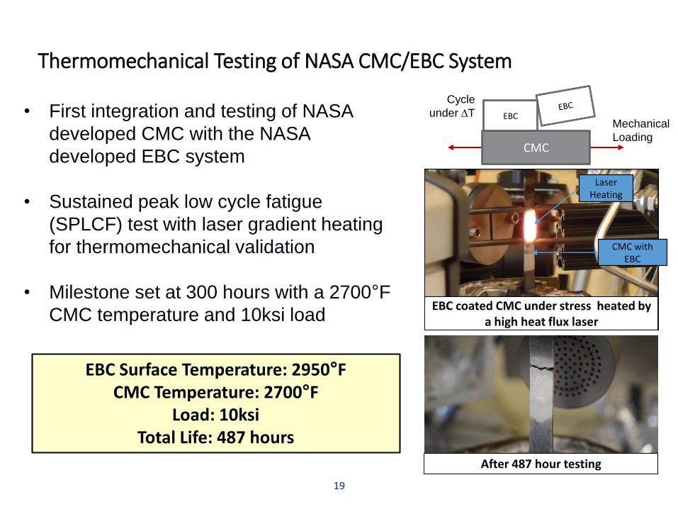
• First integration and testing of NASA
developed CMC with the NASA
developed EBC system
• Sustained peak low cycle fatigue
(SPLCF) test with laser gradient heating
for thermomechanical validation
• Milestone set at 300 hours with a 2700°F
CMC temperature and 10ksi load
Thermomechanical Testing of NASA CMC/EBC System
EBC coated CMC under stress heated by a high heat flux laser
Laser Heating
CMC with EBC
After 487 hour testing
EBC Surface Temperature: 2950°FCMC Temperature: 2700°F
Load: 10ksiTotal Life: 487 hours
Cycle
under DT
CMC
EBCMechanical
Loading
19
Title - Arial 28pt
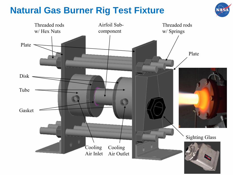
Threaded rods
w/ Springs
Airfoil Sub-
component
Gasket
Tube
Disk
Plate
Plate
Sighting Glass
Threaded rods
w/ Hex Nuts
Cooling
Air Outlet
Cooling
Air Inlet
Natural Gas Burner Rig Test Fixture
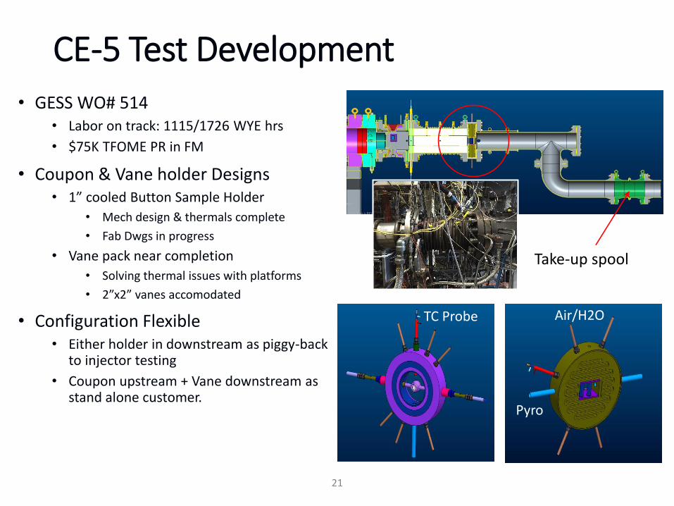
CE-5 Test Development
• GESS WO# 514• Labor on track: 1115/1726 WYE hrs
• $75K TFOME PR in FM
• Coupon & Vane holder Designs• 1” cooled Button Sample Holder
• Mech design & thermals complete
• Fab Dwgs in progress
• Vane pack near completion
• Solving thermal issues with platforms
• 2”x2” vanes accomodated
• Configuration Flexible• Either holder in downstream as piggy-back
to injector testing
• Coupon upstream + Vane downstream as stand alone customer.
21
Take-up spool
Pyro
TC Probe Air/H2O
22
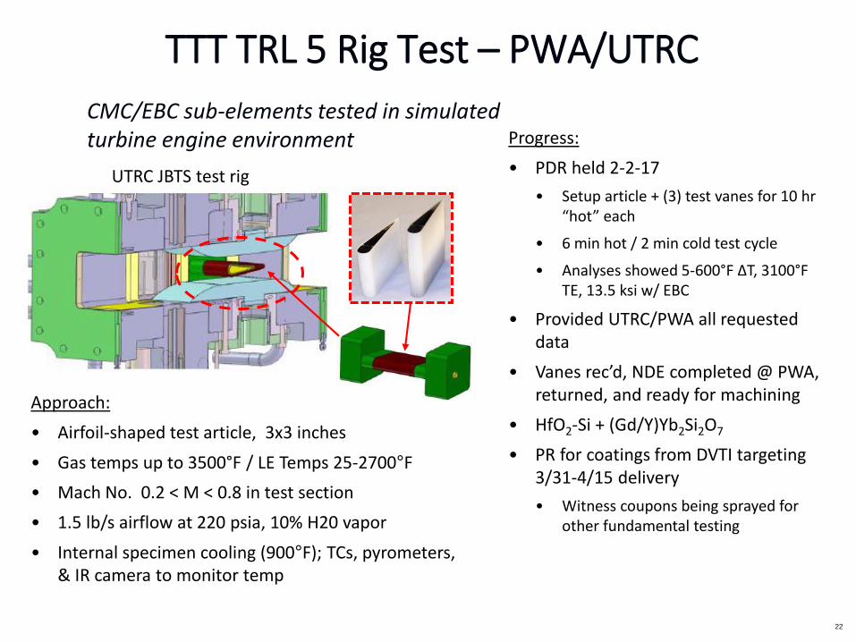
CMC/EBC sub-elements tested in simulated turbine engine environment Progress:
• PDR held 2-2-17
• Setup article + (3) test vanes for 10 hr“hot” each
• 6 min hot / 2 min cold test cycle
• Analyses showed 5-600°F ΔT, 3100°F TE, 13.5 ksi w/ EBC
• Provided UTRC/PWA all requested data
• Vanes rec’d, NDE completed @ PWA, returned, and ready for machining
• HfO2-Si + (Gd/Y)Yb2Si2O7
• PR for coatings from DVTI targeting 3/31-4/15 delivery
• Witness coupons being sprayed for other fundamental testing
UTRC JBTS test rig
TTT TRL 5 Rig Test – PWA/UTRC
Approach:
• Airfoil-shaped test article, 3x3 inches
• Gas temps up to 3500°F / LE Temps 25-2700°F
• Mach No. 0.2 < M < 0.8 in test section
• 1.5 lb/s airflow at 220 psia, 10% H20 vapor
• Internal specimen cooling (900°F); TCs, pyrometers, & IR camera to monitor temp

Processing
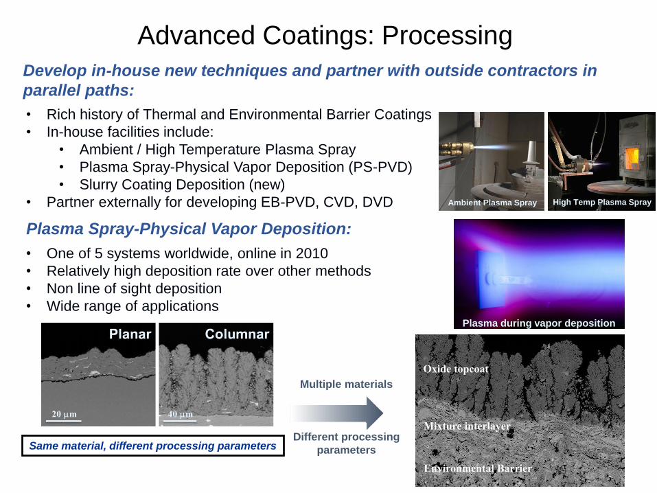
Oxide topcoat
Mixture interlayer
Environmental Barrier
Advanced Coatings: Processing
Develop in-house new techniques and partner with outside contractors in
parallel paths:
• Rich history of Thermal and Environmental Barrier Coatings
• In-house facilities include:
• Ambient / High Temperature Plasma Spray
• Plasma Spray-Physical Vapor Deposition (PS-PVD)
• Slurry Coating Deposition (new)
• Partner externally for developing EB-PVD, CVD, DVD
Plasma Spray-Physical Vapor Deposition:
Plasma during vapor deposition
Same material, different processing parameters
• One of 5 systems worldwide, online in 2010
• Relatively high deposition rate over other methods
• Non line of sight deposition
• Wide range of applications
Ambient Plasma Spray High Temp Plasma Spray
Multiple materials
Different processing
parameters

1A. Refke, et al. Proceedings of the International Thermal Spray Conference, May 14-18, (Beijing, China), 705-10 (2007).
• Bridges the gap between plasma
spray and vapor phase methods
– Variable microstructure
– Multilayer coatings with a single
deposition
• Low pressure (70-1400 Pa)
High power (>100 kW)
– Temperatures 6,000-10,000K
• High throughput1
– 0.5 m2 area, 10 mm layer in < 60s
• Material incorporated into gas stream
– Non line-of-sight deposition
• Attractive for a range of applications
– Solid oxide fuel cells, gas sensors, etc.
Plasma Spray-Physical Vapor Deposition (PS-PVD)
Plasma

PS-PVD Architectures
Environmental Barrier Coating
Thermal Barrier Coating
• Thermal Barrier Coatings– Columnar and similar to EB-PVD
– Good erosion performance and low thermal conductivity
• Environmental Barrier Coatings– Dense, similar to APS but smaller splats
• Hybrid (T/EBCs)– EBC base with a graded transition layer and a TBC topcoat
– Flexible to coating chemistry
100 mm
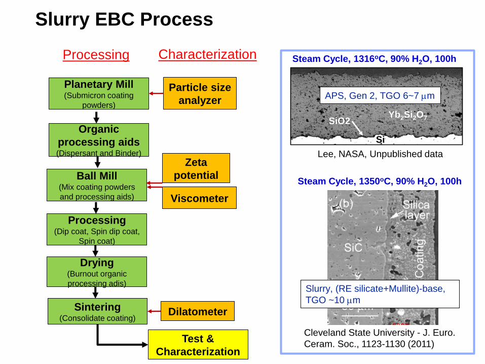
Slurry EBC Process
Planetary Mill(Submicron coating
powders)
Ball Mill(Mix coating powders
and processing aids) Viscometer
Zeta
potential
Dilatometer
Particle size
analyzer
Organic
processing aids(Dispersant and Binder)
Processing(Dip coat, Spin dip coat,
Spin coat)
Drying(Burnout organic
processing adis)
Sintering(Consolidate coating)
Test &
Characterization
Steam Cycle, 1316oC, 90% H2O, 100h
APS, Gen 2, TGO 6~7 mm
SiO2
Si
Yb2Si2O7
Steam Cycle, 1350oC, 90% H2O, 100h
Slurry, (RE silicate+Mullite)-base,
TGO ~10 mm
Cleveland State University - J. Euro.
Ceram. Soc., 1123-1130 (2011)
Lee, NASA, Unpublished data
Processing Characterization

TBCs
29
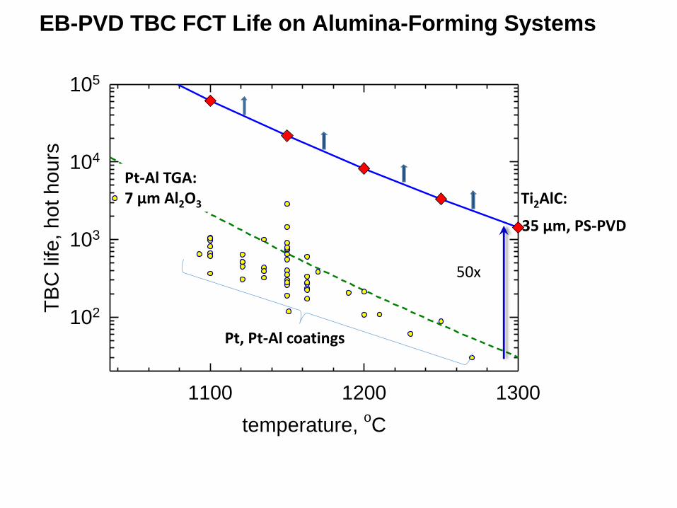
EB-PVD TBC FCT Life on Alumina-Forming Systems
temperature, oC
1100 1200 1300
TB
C life, hot hours
102
103
104
105
Ti2AlC:Pt-Al TGA: 7 µm Al2O3
35 µm, PS-PVD
Pt, Pt-Al coatings
50x
National Aeronautics and Space Administration
www.nasa.gov 30
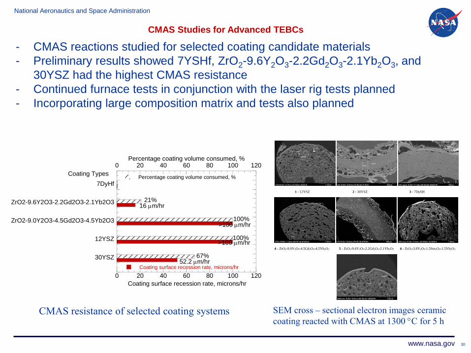
CMAS Studies for Advanced TEBCs
- CMAS reactions studied for selected coating candidate materials
- Preliminary results showed 7YSHf, ZrO2-9.6Y2O3-2.2Gd2O3-2.1Yb2O3, and
30YSZ had the highest CMAS resistance
- Continued furnace tests in conjunction with the laser rig tests planned
- Incorporating large composition matrix and tests also planned
0 20 40 60 80 100 120
0 20 40 60 80 100 120
30YSZ
12YSZ
ZrO2-9.0Y2O3-4.5Gd2O3-4.5Yb2O3
ZrO2-9.6Y2O3-2.2Gd2O3-2.1Yb2O3
7DyHf
Coating surface recession rate, microns/hr
Percentage coating volume consumed, %
Coating surface recession rate, microns/hr
Percentage coating volume consumed, %
Coating Types
>100 mm/hr
>100 mm/hr
100%
100%
16 mm/hr
52.2 mm/hr
21%
67%
1 - 12YSZ 2 - 30YSZ 3 - 7DySH
4 - ZrO2-9.0Y2O3-4.5Gd2O3-4.5Yb2O3 5 - ZrO2-9.6Y2O3-2.2Gd2O3-2.1Yb2O3 6 - ZrO2-3.0Y2O3-1.5Sm2O3-1.5Yb2O3
SEM cross – sectional electron images ceramic
coating reacted with CMAS at 1300 C for 5 hCMAS resistance of selected coating systems

Challenges & Potential Collaborations

Title - Arial 28pt
EBC Challenges
EBCs with 2700oF interfacial temperature capability to enable 2700oF CMC
CMAS mitigation to break the upper temperature limit of EBCs due to CMC degradation
A long-life EBC and a robust EBC lifing method to improve the reliability of CMC
EBC Testing methods relevant to engines to validate EBC life
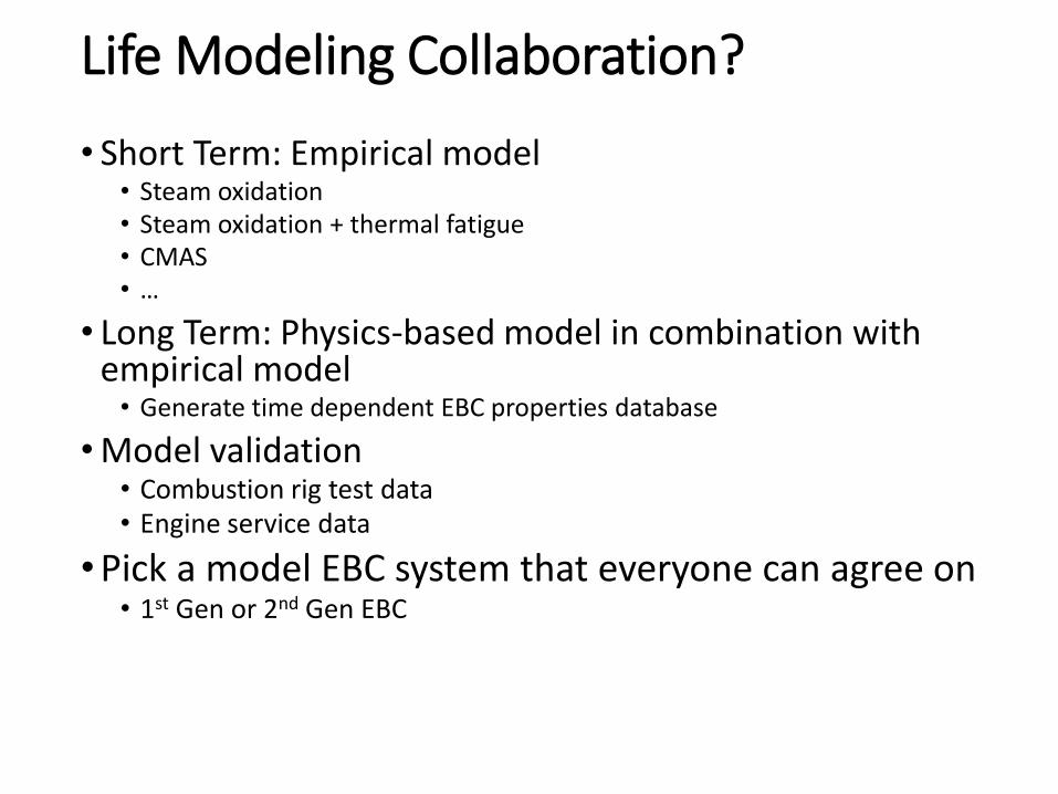
Life Modeling Collaboration?
• Short Term: Empirical model• Steam oxidation• Steam oxidation + thermal fatigue• CMAS• …
• Long Term: Physics-based model in combination with empirical model
• Generate time dependent EBC properties database
• Model validation• Combustion rig test data• Engine service data
• Pick a model EBC system that everyone can agree on• 1st Gen or 2nd Gen EBC

Backup
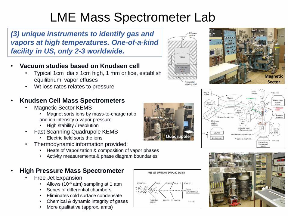
LME Mass Spectrometer Lab(3) unique instruments to identify gas and
vapors at high temperatures. One-of-a-kind
facility in US, only 2-3 worldwide.
• Vacuum studies based on Knudsen cell • Typical 1cm dia x 1cm high, 1 mm orifice, establish near
equilibrium, vapor effuses
• Wt loss rates relates to pressure
• Knudsen Cell Mass Spectrometers• Magnetic Sector KEMS
• Magnet sorts ions by mass-to-charge ratio
and ion intensity α vapor pressure
• High stability / resolution
• Fast Scanning Quadrupole KEMS• Electric field sorts the ions
• Thermodynamic information provided:• Heats of Vaporization & composition of vapor phases
• Activity measurements & phase diagram boundaries
• High Pressure Mass Spectrometer• Free Jet Expansion
• Allows (10-6 atm) sampling at 1 atm
• Series of differential chambers
• Eliminates cold surface condensate
• Chemical & dynamic integrity of gases
• More qualitative (approx. amts)
MagneticSector
Quadrupole
36
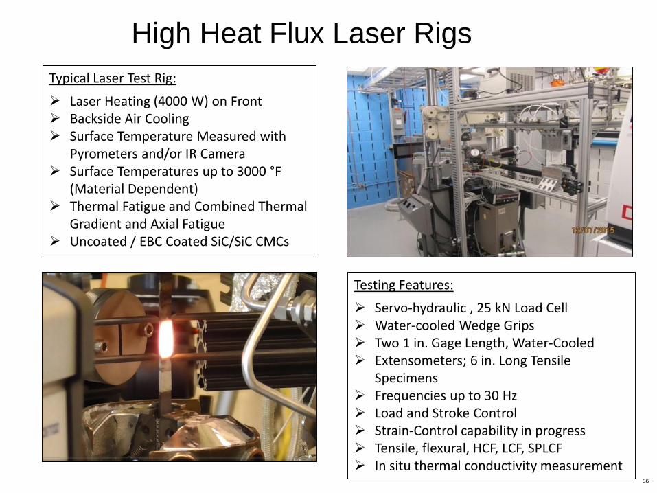
Typical Laser Test Rig:
Laser Heating (4000 W) on Front Backside Air Cooling Surface Temperature Measured with
Pyrometers and/or IR Camera Surface Temperatures up to 3000 °F
(Material Dependent) Thermal Fatigue and Combined Thermal
Gradient and Axial Fatigue Uncoated / EBC Coated SiC/SiC CMCs
(HO)
(H2O)
Testing Features:
Servo-hydraulic , 25 kN Load Cell Water-cooled Wedge Grips Two 1 in. Gage Length, Water-Cooled Extensometers; 6 in. Long Tensile
Specimens Frequencies up to 30 Hz Load and Stroke Control Strain-Control capability in progress Tensile, flexural, HCF, LCF, SPLCF In situ thermal conductivity measurement
High Heat Flux Laser Rigs
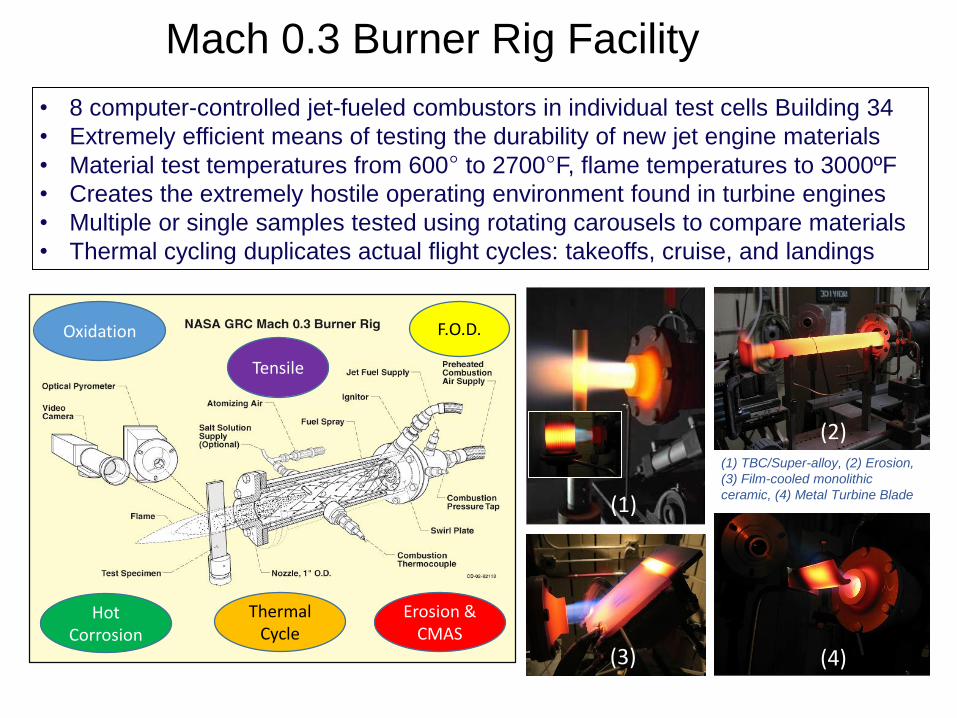
• 8 computer-controlled jet-fueled combustors in individual test cells Building 34
• Extremely efficient means of testing the durability of new jet engine materials
• Material test temperatures from 600° to 2700°F, flame temperatures to 3000ºF
• Creates the extremely hostile operating environment found in turbine engines
• Multiple or single samples tested using rotating carousels to compare materials
• Thermal cycling duplicates actual flight cycles: takeoffs, cruise, and landings
Mach 0.3 Burner Rig Facility
(1) TBC/Super-alloy, (2) Erosion,
(3) Film-cooled monolithic
ceramic, (4) Metal Turbine Blade(1)
(3)
(2)
(4)
Oxidation
Hot Corrosion
Thermal Cycle
Erosion & CMAS
Tensile
F.O.D.
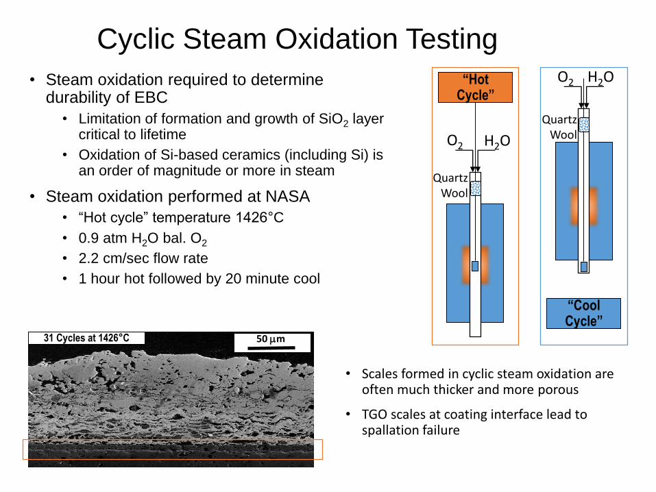
Cyclic Steam Oxidation Testing
O2 H2O
QuartzWool
“Hot Cycle”
• Steam oxidation required to determine durability of EBC
• Limitation of formation and growth of SiO2 layer critical to lifetime
• Oxidation of Si-based ceramics (including Si) is an order of magnitude or more in steam
• Steam oxidation performed at NASA
• “Hot cycle” temperature 1426°C
• 0.9 atm H2O bal. O2
• 2.2 cm/sec flow rate
• 1 hour hot followed by 20 minute cool
O2 H2O
QuartzWool
“Cool Cycle”
31 Cycles at 1426°C 50 mm
• Scales formed in cyclic steam oxidation are often much thicker and more porous
• TGO scales at coating interface lead to spallation failure
39
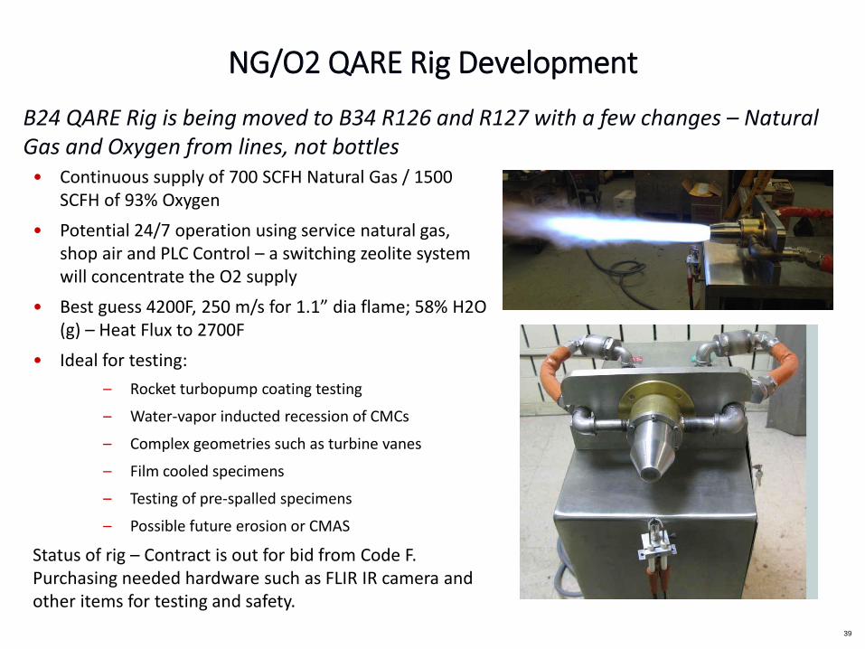
B24 QARE Rig is being moved to B34 R126 and R127 with a few changes – Natural Gas and Oxygen from lines, not bottles
• Continuous supply of 700 SCFH Natural Gas / 1500 SCFH of 93% Oxygen
• Potential 24/7 operation using service natural gas, shop air and PLC Control – a switching zeolite system will concentrate the O2 supply
• Best guess 4200F, 250 m/s for 1.1” dia flame; 58% H2O (g) – Heat Flux to 2700F
• Ideal for testing:
– Rocket turbopump coating testing
– Water-vapor inducted recession of CMCs
– Complex geometries such as turbine vanes
– Film cooled specimens
– Testing of pre-spalled specimens
– Possible future erosion or CMAS
Status of rig – Contract is out for bid from Code F. Purchasing needed hardware such as FLIR IR camera and other items for testing and safety.
NG/O2 QARE Rig Development

Steam Cycling Rig Progress Update (Lee, Harder)
• Four steam cycling rigs employing a vertical tube furnace coupled with a mechanical lift are in operating conditions
• A new higher capacity steam cycling rig employing a horizontal tube furnace coupled with a mechanical actuator is being designed (Ed Sechkar)
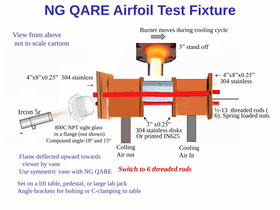
2.5”, ¼” wall
304 cylinders
Flame deflected upward towards
viewer by vane
Use symmetric vane with NG QARE
Set on a lift table, pedestal, or large lab jack
Angle brackets for bolting or C-clamping to table
4”x8”x0.25”304 stainless
½-13 threaded rods ( 6). Spring loaded nuts
Air in
Switch to 6 threaded rods
Burner moves during cooling cycle
4”x8”x0.25” 304 stainless
→
3” x0.25” 304 stainless disksOr printed IN625
Ircon 5r
3” stand off
800C NPT sight glass
in a flange (not shown)
Compound angle:18° and 15°
NG QARE Airfoil Test Fixture
View from above
not to scale cartoon
Colling
Air outCooling
Air In


