47
LIQUEFIED NATURAL GAS (LNG) – An Introduction 14 th April 2009 P resented By: N. MA NIK ANDAN
7/23/2019 LNG an Introduction
http://slidepdf.com/reader/full/lng-an-introduction 1/60
LIQUEFIEDNATURAL GAS
(LNG) –
An Introduction
14th
April 2009
Pr e s e n t e d B y : N . MA N I K ANDAN
7/23/2019 LNG an Introduction
http://slidepdf.com/reader/full/lng-an-introduction 2/60
2Liquefied Natural Gas - An Introduction
I. LNG OVERVIEW
II. TECHNIP’S LNG CAPABILITY
III. LNG MANUFACTURING PROCESS
IV. LIQUEFACTION TECHNOLOGIES
V. CRITICAL EQUIPMENT
VI. LNG REGASIFICATION
Contents
7/23/2019 LNG an Introduction
http://slidepdf.com/reader/full/lng-an-introduction 3/60
3Liquefied Natural Gas - An Introduction
LNG OVERVIEW
►LNG is Natural Gas reduced to liquid state by cooling it to –162ºC
►LNG is colorless, odorless, non-toxic and the gaseous form is lighter
than air
►Natural gas required to manufacture LNG – from gas reservoirs often
offshore
►Gas produced from two different kinds of reservoirs, each requiring a
different processing technique.
– Gas reservoirs – produced at High Pressure
– Oil reservoirs – oil-gas dispersion/mixed phase or oil reservoir
gas caps; relatively lower pressure

7/23/2019 LNG an Introduction
http://slidepdf.com/reader/full/lng-an-introduction 4/60
4Liquefied Natural Gas - An Introduction
LNG OVERVIEW
Ethane (C2H6)
HEAVIER FRACTIONS also referred to as:
C5+
Pentanes Plus
Natural Gasoline
Condensate
NGL
Propane (C3H8)
Butane (C4H10)LPG
NATURAL
GASex-well
Methane (CH4 )
Non-Hydrocarbons
H2O, CO2, H2S, N2, Hg, etc.
LIQUID AT 1 Bar
n-Butane –0.5ºC
i-Butane –12ºC
Propane –42ºC
Ethane –88ºC
Ethylene –103ºC
Methane –161ºC
Oxygen –184ºC
Nitrogen –196ºCH2 –253ºC
Helium –269ºC

7/23/2019 LNG an Introduction
http://slidepdf.com/reader/full/lng-an-introduction 5/60
5Liquefied Natural Gas - An Introduction
Why should Natural Gas be liquefied?
►Liquefaction reduces gas volume by approx. 600 times.
►More economical for liquid transport
– through ship – between countries/continents
– through road carriers – in land.
►For remote gas fields (especially offshore) pipeline transportationof gas is expensive – hence natural gas is liquefied before
transportation

7/23/2019 LNG an Introduction
http://slidepdf.com/reader/full/lng-an-introduction 6/60
6Liquefied Natural Gas - An Introduction
WHY WE NEED LNG?
Growing power demand in the world and forecast
that by 2050 energy needs will double that of today –
gas is a cheaper source of fuel.Oil companies under pressure to reduce gas flaring
– develop strategies for dealing with gas.
Growing demand for cleaner fuels – gas is thepreferred choice for large-scale power plants.
Reservoir recovery – on an average about 60% of
the gas in the reservoir is recoverable, as comparedto 33% of an oil deposit.

7/23/2019 LNG an Introduction
http://slidepdf.com/reader/full/lng-an-introduction 7/60
7Liquefied Natural Gas - An Introduction
NG – A CLEAN FUEL COMPARED TO DIESEL
Values in grams/kWH power generation
0.050.15PM
0.51HC
17NOx
415.5CO
Flue gas from
NG burning
Flue gas from
Diesel burning
7/23/2019 LNG an Introduction
http://slidepdf.com/reader/full/lng-an-introduction 8/60
8Liquefied Natural Gas - An Introduction
How is LNG/NG Measured?
►Natural Gas is measured in• Volume units, i.e. cubic feet or cubic meters
• Energy Units, i.e. Million BTU or Million kCalories
►VOLUME UNITS
• Supplies to Power plants measured in Million standard cubic feet/day (MMSCFD)
or Million standard cubic meter/day (MMSCMD).• Resources and reserves calculated in Trillions of standard cubic feet (Tcf).
A Gas field containing 3.65 TCF ≡ around 12 MMSCMD gas for 25 years
A rough way of visualizing a trillion cubic feet of gas ≡ imagine enough of
product to fill a cube with its sides two miles long►ENERGY VALUES
• Amount of energy obtained from the burning unit volume of Natural Gas measured inBritish Thermal Unit (BTU) or kCalorie or kJoule.
►
At sea level, it takes about 75 BTU (19 kCal) to make a cup of tea.►A cubic feet of natural gas gives off about 1050 BTU (depends on quality of
gas) » one cubic feet of Natural Gas may make 14 cups of tea
► 1 BTU = 0.252 kCalories = 1.055 kJoules
7/23/2019 LNG an Introduction
http://slidepdf.com/reader/full/lng-an-introduction 9/60
9Liquefied Natural Gas - An Introduction
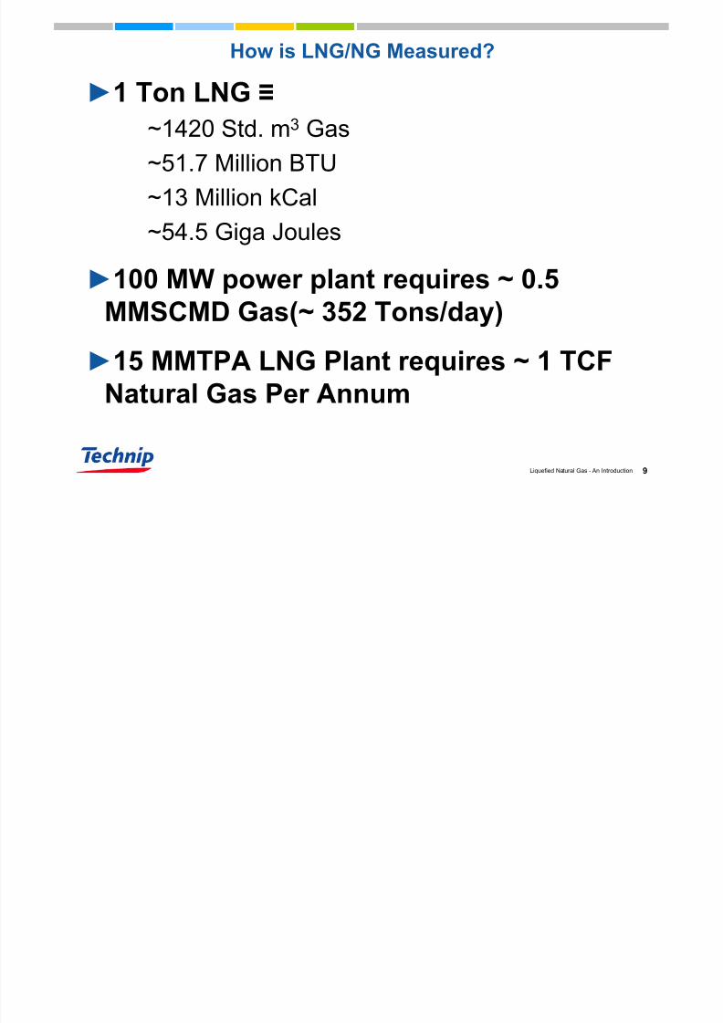
How is LNG/NG Measured?
►1 Ton LNG ≡
~1420 Std. m3 Gas
~51.7 Million BTU
~13 Million kCal
~54.5 Giga Joules
►100 MW power plant requires ~ 0.5
MMSCMD Gas(~ 352 Tons/day)
►15 MMTPA LNG Plant requires ~ 1 TCFNatural Gas Per Annum

7/23/2019 LNG an Introduction
http://slidepdf.com/reader/full/lng-an-introduction 10/60
10Liquefied Natural Gas - An Introduction
Upstream
Treatment andLiquefaction
Transportation
Regasification
Marketing
LNG Chain
7/23/2019 LNG an Introduction
http://slidepdf.com/reader/full/lng-an-introduction 11/60
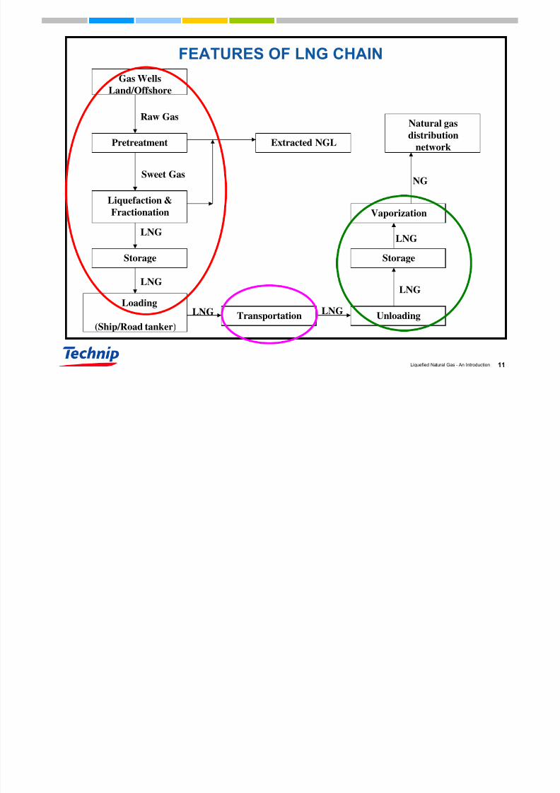
11Liquefied Natural Gas - An Introduction
NG
LNG
LNG
LNGLNG
LNG
LNG
Raw Gas
Gas Wells
Land/Offshore
Pretreatment
Liquefaction &
Fractionation
Storage
Extracted NGL
Loading
(Ship/Road tanker)Transportation Unloading
Storage
Vaporization
Natural gas
distributionnetwork
FEATURES OF LNG CHAIN
Sweet Gas
7/23/2019 LNG an Introduction
http://slidepdf.com/reader/full/lng-an-introduction 12/60
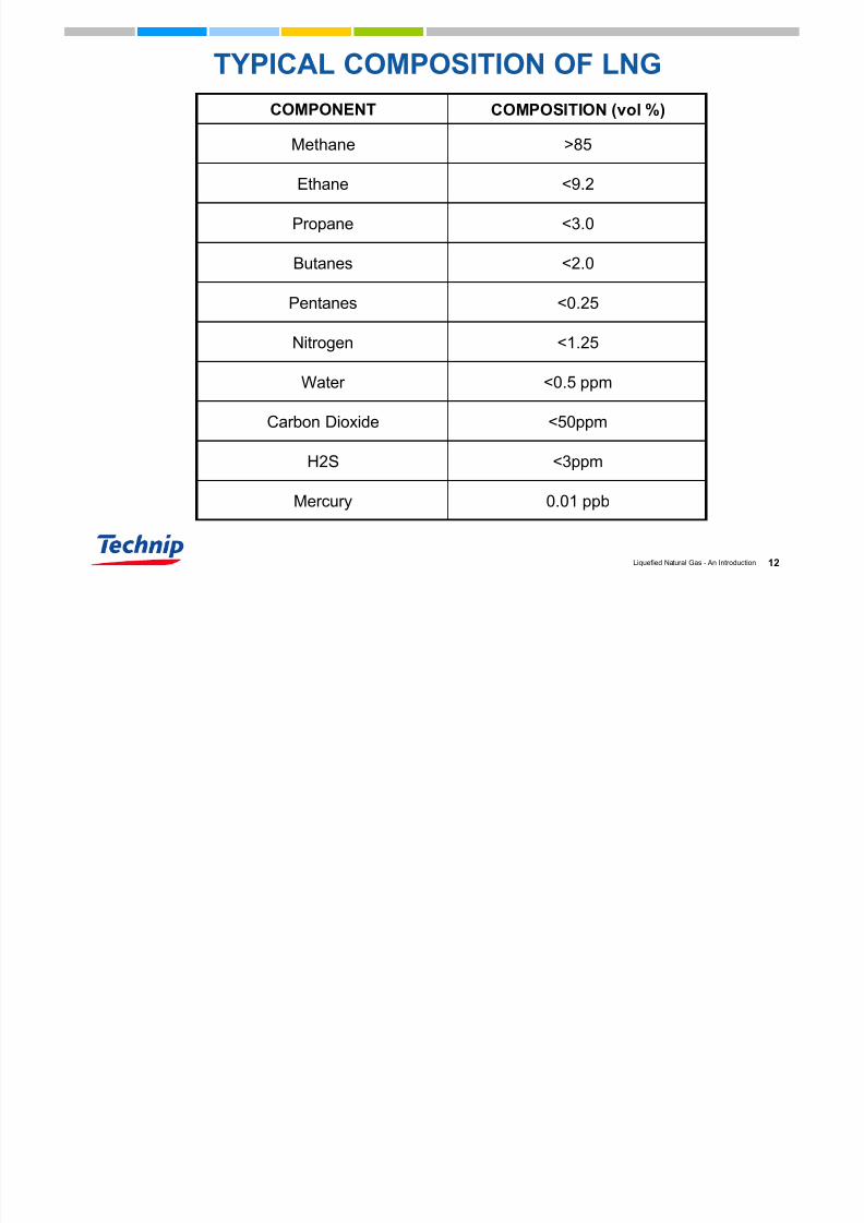
12Liquefied Natural Gas - An Introduction
TYPICAL COMPOSITION OF LNG
0.01 ppbMercury
<3ppmH2S
<1.25Nitrogen
<0.5 ppmWater
<50ppm
<0.25
<2.0
<3.0
<9.2
>85
COMPOSITION (vol %)
Carbon Dioxide
Pentanes
Butanes
Propane
Ethane
Methane
COMPONENT
7/23/2019 LNG an Introduction
http://slidepdf.com/reader/full/lng-an-introduction 13/60
TECHNIP’SLNG Capability

7/23/2019 LNG an Introduction
http://slidepdf.com/reader/full/lng-an-introduction 14/60
14Liquefied Natural Gas - An Introduction
Technip in the LNG chain
GAS FIELDS►Nigeria
• Obite
• Amenam
►
Brunei• OPP
►Qatar • Qatargas
• QGII
► Indonesia• Tunu
• Peciko
►Egypt• Samian Sapphire
TERMINALS► Freeport
► Enagas
Barcelona
► Gulf LNG
LIQUEFACTION► Algeria
► Nigeria• NLNG Tr 1+2
• NLNG Tr 3
• NLNG Tr 4+5• NLNG Tr 6
• NLNG Tr 7+8
• OK LNG
► Qatar • Qatargas expansion
• QGII
• QGIII/IV
• Rasgas III
► Yemen
► Iran
► Indonesia• Bontang I
Turnkey solutions for reduced cost marine works
7/23/2019 LNG an Introduction
http://slidepdf.com/reader/full/lng-an-introduction 15/60
15Liquefied Natural Gas - An Introduction
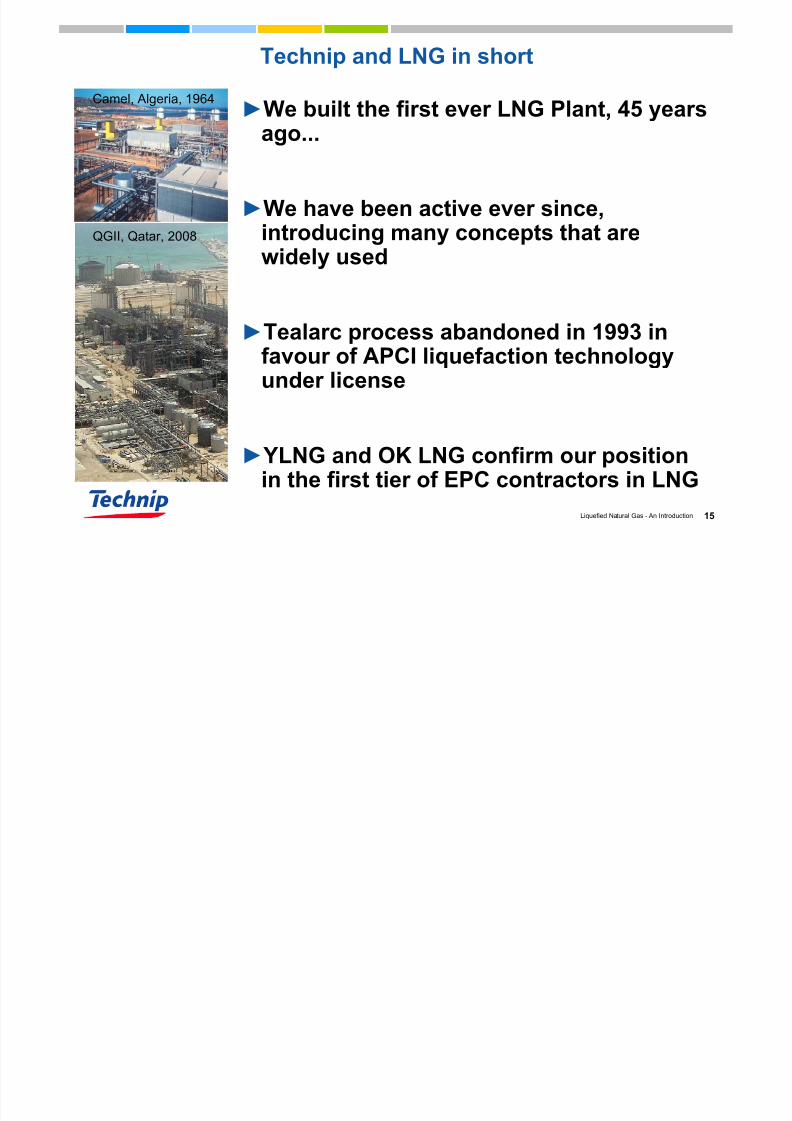
Technip and LNG in short
►We built the first ever LNG Plant, 45 yearsago...
►We have been active ever since,introducing many concepts that arewidely used
►Tealarc process abandoned in 1993 infavour of APCI liquefaction technologyunder license
► YLNG and OK LNG confirm our position
in the first tier of EPC contractors in LNG
Camel, Algeria, 1964
QGII, Qatar, 2008
7/23/2019 LNG an Introduction
http://slidepdf.com/reader/full/lng-an-introduction 16/60
16Liquefied Natural Gas - An Introduction
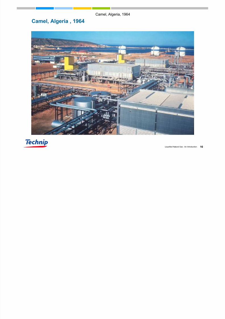
Camel, Algeria, 1964
Camel, Algeria , 1964

7/23/2019 LNG an Introduction
http://slidepdf.com/reader/full/lng-an-introduction 17/60
17Liquefied Natural Gas - An Introduction
Three Mega LNG Projects in Qatar
► Qatargas II: construction of 2 of the world’s
largest LNG trains (4 & 5) with a total capacity of
15.6 million tons/year
► Qatargas III and IV: construction 2 additional
trains (6 & 7)
► Rasgas III: construction 2 trains (6 & 7)
Technip, in a joint venture,
is building the 6 largest LNG trains in the
world, with a capacity of 7.8 milliontons/year each.
Qatargas II
SaudiArabia
Qatar
7/23/2019 LNG an Introduction
http://slidepdf.com/reader/full/lng-an-introduction 18/60
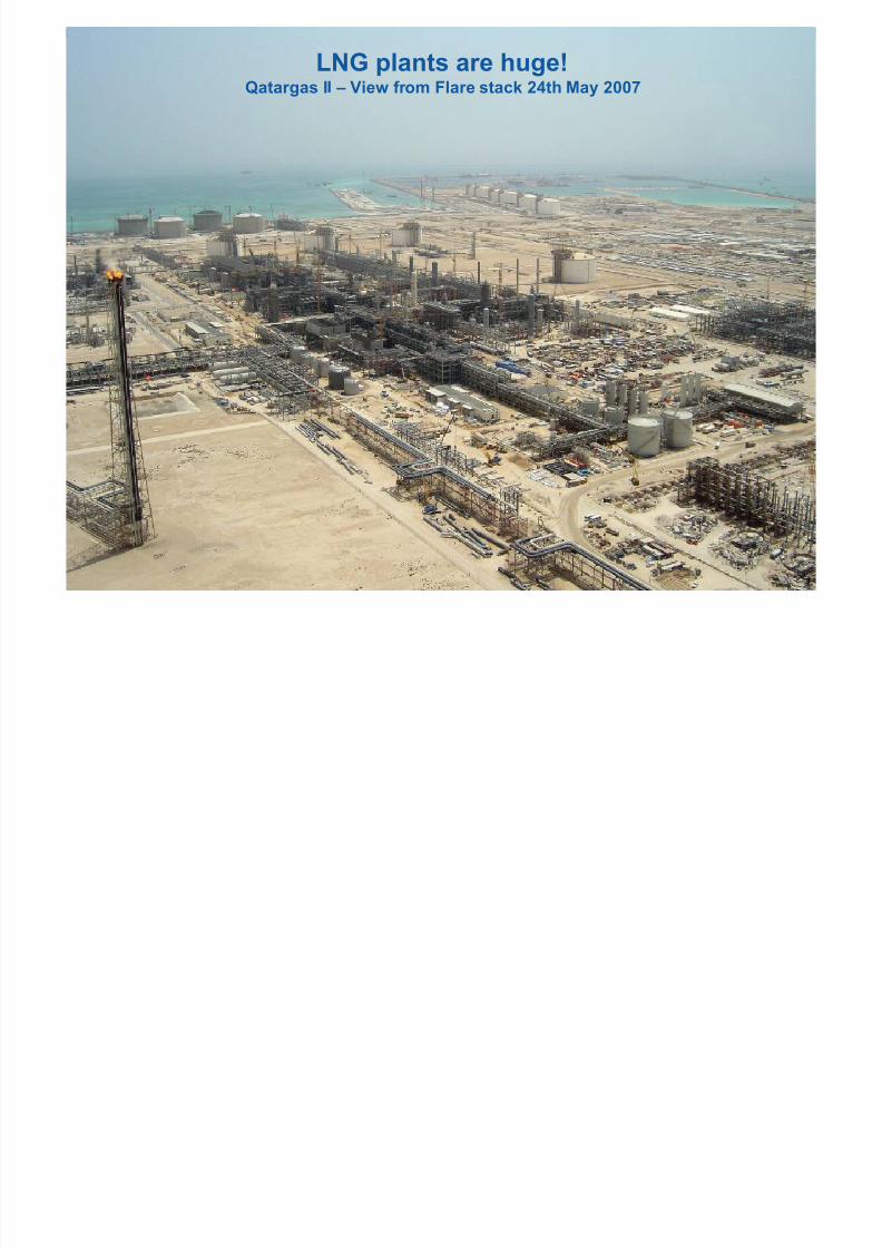
18Liquefied Natural Gas - An Introduction
LNG plants are huge!Qatargas II – View from Flare stack 24th May 2007
7/23/2019 LNG an Introduction
http://slidepdf.com/reader/full/lng-an-introduction 19/60
19Liquefied Natural Gas - An Introduction
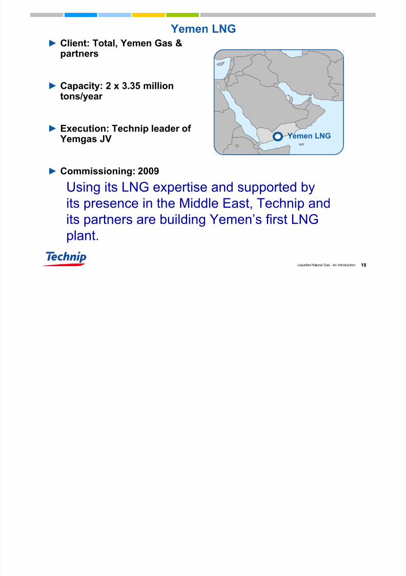
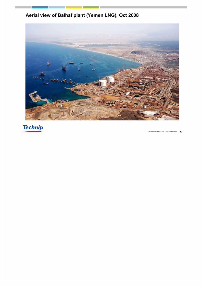
Yemen LNG
► Client: Total, Yemen Gas &
partners
► Capacity: 2 x 3.35 milliontons/year
► Execution: Technip leader of Yemgas JV
► Commissioning: 2009
Using its LNG expertise and supported by
its presence in the Middle East, Technip andits partners are building Yemen’s first LNG
plant.
Yemen LNG
7/23/2019 LNG an Introduction
http://slidepdf.com/reader/full/lng-an-introduction 20/60
20Liquefied Natural Gas - An Introduction
Aerial view of Balhaf plant (Yemen LNG), Oct 2008

7/23/2019 LNG an Introduction
http://slidepdf.com/reader/full/lng-an-introduction 21/60
21Liquefied Natural Gas - An Introduction
Shtokman LNG (FEED)► Client: Shtokman Development AG
► Gazprom 51%• Total 25%
• StatoilHydro 24%
► Location: Teriberka, near Murmansk
• One 7.5 Mt/y LNG train, APCI C3/MCR
• One gas export train
► FEED by Technip to be completed mid-2009
Technip is engineering the
LNG and gas plant facilities
for the first phase of
development of the largestundeveloped gas field in the
world.
Shtokman LNG site
7/23/2019 LNG an Introduction
http://slidepdf.com/reader/full/lng-an-introduction 22/60
22Liquefied Natural Gas - An Introduction
II. LNG MANUFACTURING
PROCESS

7/23/2019 LNG an Introduction
http://slidepdf.com/reader/full/lng-an-introduction 23/60
23Liquefied Natural Gas - An Introduction
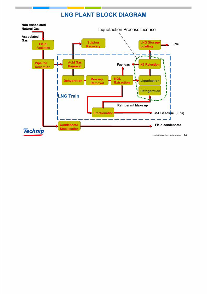
LNG Manufacturing Process
Receiving gas from wells and manifolds Pressure control/reduction
Inlet gas-condensate-water separation
Feed gas compression
Acid gas removal
Gas Dehydration
Mercury removal
Liquefaction
LIQUEFACTION FORMS THE HEART OF ANY LNG
MANUFACTURING FACILITY
End flash
LNG Storage and loading
Fractionation of C1, C2, C3, C4 and NGL (i.e. Demethanizer, Deethanizer,
Depropanizer and Debutanizer)
Condensate/NGL Storage and loading
Feed gas pretreatment
7/23/2019 LNG an Introduction
http://slidepdf.com/reader/full/lng-an-introduction 24/60
24Liquefied Natural Gas - An Introduction
LNG PLANT BLOCK DIAGRAM
Sulphur
Recovery
Liquefaction
Field
Facilities
Non Associated
Natural Gas
Associated
GasLNG Storage
Loading
Fractionation (LPG)C5+ Gasoline
Dehydration
Condensate
Stabilisation
MercuryRemoval
NGLExtraction
Refrigeration
Refrigerant Make up
LNG
Field condensate
N2 RejectionPipeline
Reception
Acid Gas
RemovalFuel gas
Liquefaction Process License
LNG Train
7/23/2019 LNG an Introduction
http://slidepdf.com/reader/full/lng-an-introduction 25/60
25Liquefied Natural Gas - An Introduction
III. NG LIQUEFACTION
TECHNOLOGIES
7/23/2019 LNG an Introduction
http://slidepdf.com/reader/full/lng-an-introduction 26/60
26Liquefied Natural Gas - An Introduction
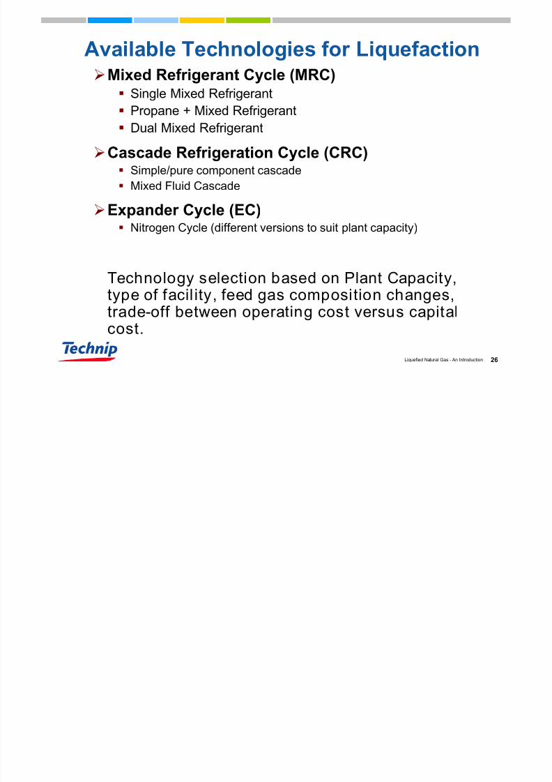
Available Technologies for Liquefaction
Mixed Refrigerant Cycle (MRC) Single Mixed Refrigerant
Propane + Mixed Refrigerant
Dual Mixed Refrigerant
Cascade Refrigeration Cycle (CRC) Simple/pure component cascade
Mixed Fluid Cascade
Expander Cycle (EC) Nitrogen Cycle (different versions to suit plant capacity)
Technology selection based on Plant Capacity,type of facil ity, feed gas composition changes,trade-off between operating cost versus capitalcost.

7/23/2019 LNG an Introduction
http://slidepdf.com/reader/full/lng-an-introduction 27/60
27Liquefied Natural Gas - An Introduction
CYCLE EFFICIENCY COMPARISON
7/23/2019 LNG an Introduction
http://slidepdf.com/reader/full/lng-an-introduction 28/60
28Liquefied Natural Gas - An Introduction
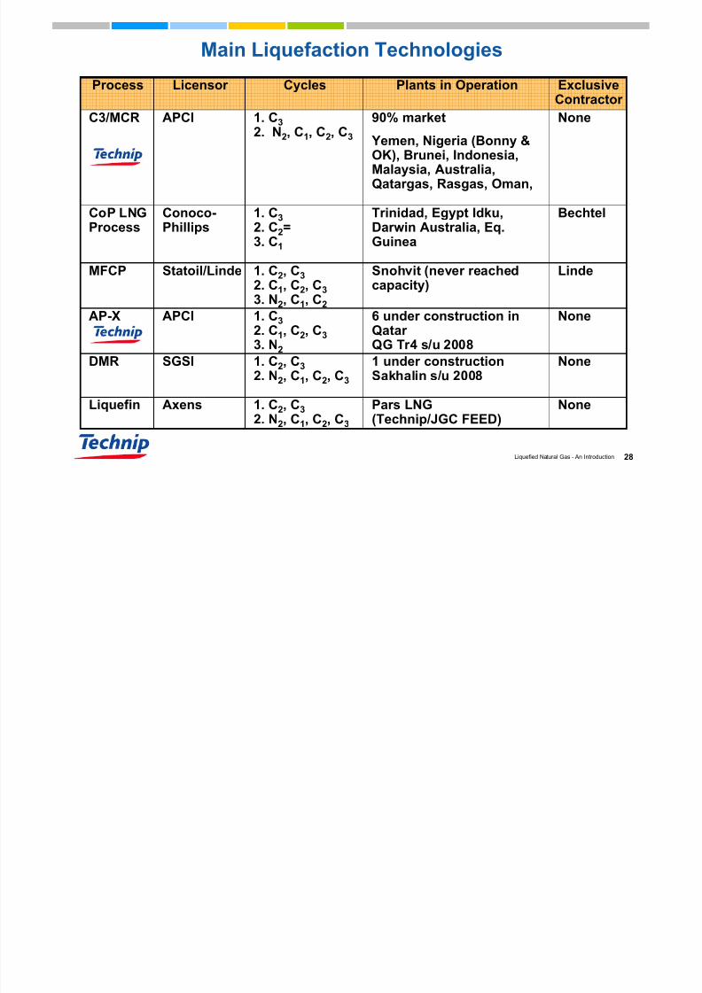
Main Liquefaction Technologies
LindeSnohvit (never reachedcapacity)
1. C2, C3
2. C1, C2, C3
3. N2, C1, C2
Statoil/LindeMFCP
NonePars LNG(Technip/JGC FEED)
1. C2, C3
2. N2, C1, C2, C3
AxensLiquefin
None1 under constructionSakhalin s/u 2008
1. C2, C3
2. N2, C1, C2, C3
SGSIDMR
None6 under construction inQatar
QG Tr4 s/u 2008
1. C3
2. C1, C2, C3
3. N2
APCIAP-X
BechtelTrinidad, Egypt Idku,Darwin Australia, Eq.Guinea
1. C3
2. C2=3. C1
Conoco-Phillips
CoP LNGProcess
None90% market
Yemen, Nigeria (Bonny &OK), Brunei, Indonesia,Malaysia, Australia,Qatargas, Rasgas, Oman,
1. C3
2. N2, C1, C2, C3
APCIC3/MCR
ExclusiveContractor Plants in OperationCyclesLicensor Process

7/23/2019 LNG an Introduction
http://slidepdf.com/reader/full/lng-an-introduction 29/60
29Liquefied Natural Gas - An Introduction
Types of refrigeration cycles for Liquefaction
Reverse Rankine Cycles
Used in large liquefaction plants
Mixed Refrigerant Cycles
Pure Component Cycles
Hybrid e.g. pure propane cycle and one mixed refrigerant cycle
Reverse Brayton Cycles
Small peak shaving units, LNG carrier boil off gas re-liquefaction
Nitrogen cycles

7/23/2019 LNG an Introduction
http://slidepdf.com/reader/full/lng-an-introduction 30/60
30Liquefied Natural Gas - An Introduction
MIXED REFRIGERANT CYCLE (MRC)
► Sweet gas pre-cooling done by propane
► Liquefaction done by main mixed refrigerant (MR)
►Mixture comprises of Nitrogen and hydrocarbons (C1to C3).
► Mixture composition specified such that liquid
refrigerant evaporates over a temperature range
similar to that of liquefaction.
Advantages
Simple configuration
Higher thermodynamic efficiency
Fewer items of machinery
Only one or two compressors for refrigerant compression
7/23/2019 LNG an Introduction
http://slidepdf.com/reader/full/lng-an-introduction 31/60
31Liquefied Natural Gas - An Introduction
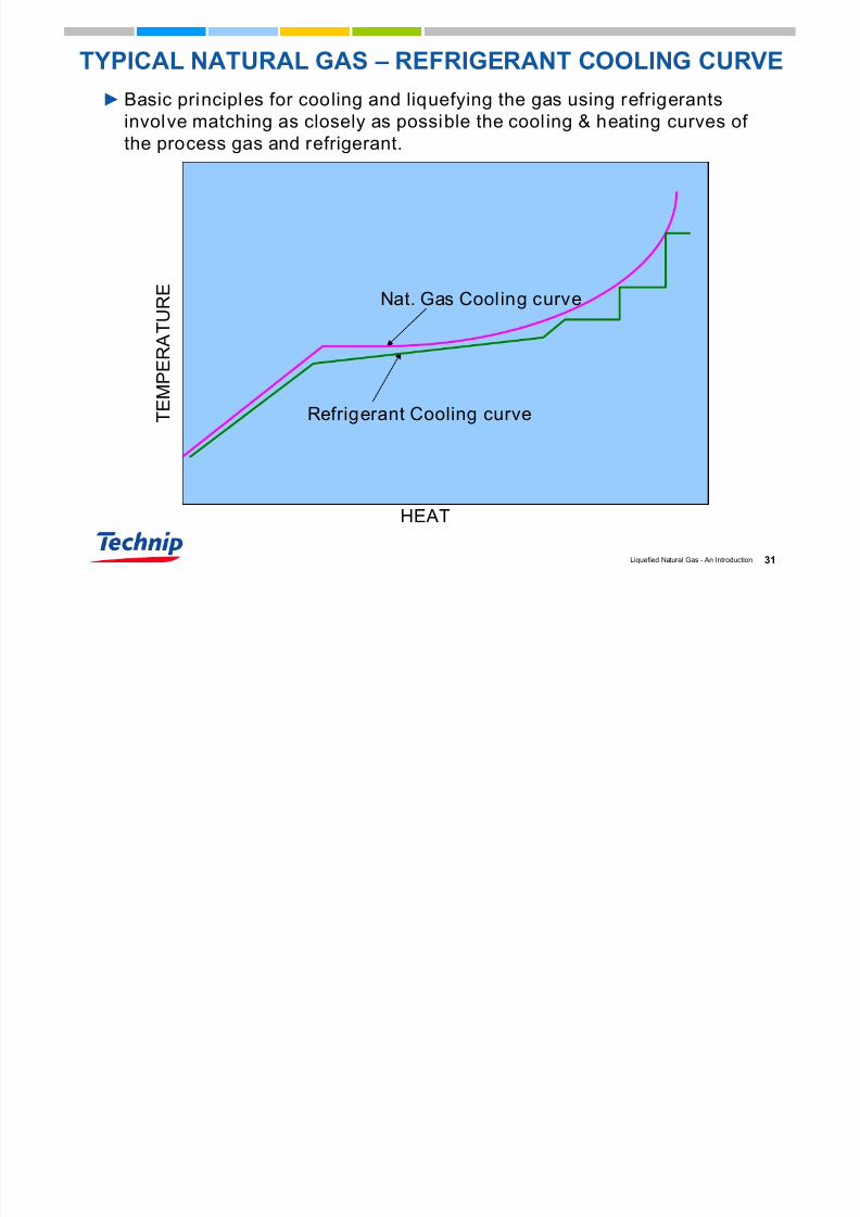
TYPICAL NATURAL GAS – REFRIGERANT COOLING CURVE
►Basic principles for cooling and liquefying the gas using refrigerants
involve matching as closely as possible the cooling & heating curves of
the process gas and refrigerant.
T E M P E R A T U R E
HEAT
Nat. Gas Cooling curve
Refrigerant Cooling curve
7/23/2019 LNG an Introduction
http://slidepdf.com/reader/full/lng-an-introduction 32/60
32Liquefied Natural Gas - An Introduction
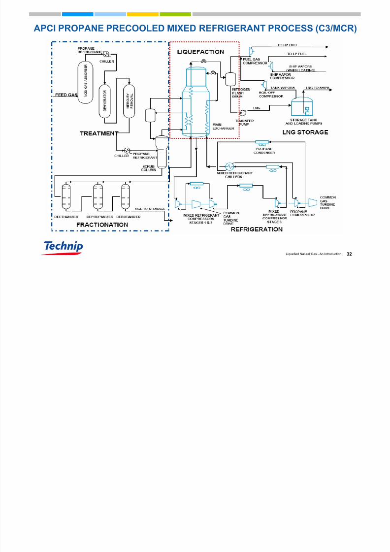
APCI PROPANE PRECOOLED MIXED REFRIGERANT PROCESS (C3/MCR)

7/23/2019 LNG an Introduction
http://slidepdf.com/reader/full/lng-an-introduction 33/60
33Liquefied Natural Gas - An Introduction
HP-MRPROPANE
HP-MRPROPANE
NG Liquefaction with Mixed Refrigerant (C3/MCR)
0
20
-20
-60
-40
-80
-120
-100
-140
-180
-160
2 0 0
6 0 0
1 0 0 0
1 4 0 0
1 8 0 0
2 2 0 0
2 6 0 0
3 0 0 0
3 4 0 0
Temperature (°C)
H (kcal/kmole)
Water or Air
Propane Cycle
Dew Pt
B Pt Liquefaction Refrigerant
7/23/2019 LNG an Introduction
http://slidepdf.com/reader/full/lng-an-introduction 34/60
34Liquefied Natural Gas - An Introduction
LICENSOR’S FOCUS
THREE ASPECTS OF LNG PRODUCTION
► COMPRESSION REQUIRED FOR REFRIGERATION CYCLES
► POWER TO DRIVE REFRIGERATION CYCLES
- EARLIER PLANTS USED STEAM TURBINES
- CURRENT INDUSTRY NORM IS COMBUSTION GAS TURBINES OR
ELECTRIC MOTORS
► MAIN CRYOGENIC HEAT EXCHANGER TO CHILL THE INCOMING GAS
- SPIRAL WOUND HEAT EXCHANGER (SWHE) DOMINATED MARKET
- BRAZED ALUMINIUM PLATE-FIN HEAT EXCHANGERS CHALLENGE
DOMINANCE OF SWHE
7/23/2019 LNG an Introduction
http://slidepdf.com/reader/full/lng-an-introduction 35/60
35Liquefied Natural Gas - An Introduction
IV.CRITICAL EQUIPMENT
C C Q G
7/23/2019 LNG an Introduction
http://slidepdf.com/reader/full/lng-an-introduction 36/60
36Liquefied Natural Gas - An Introduction
CRITICAL EQUIPMENT IN LNG PLANT
►CRYOGENIC HEAT EXCHANGERS
►LARGE COMPRESSORS – CENTRIFUGAL AND/OR AXIAL
►LARGE DRIVERS FOR COMPRESSORS (>50MW DRIVERS) –
GAS TURBINES OR MOTORS
►LARGE COOLERS FOR COMPRESSOR INTERSTAGE (AIR
COOLED OR SEA WATER COOLED)
►LARGE UTILITY SYSTEMS
►LARGE CRYOGENIC STORAGE TANKS
T f H t E h f Li f ti
7/23/2019 LNG an Introduction
http://slidepdf.com/reader/full/lng-an-introduction 37/60
37Liquefied Natural Gas - An Introduction
Types of Heat Exchangers for Liquefaction
(Main Cryogenic Heat Exchangers – MCHE)
Spiral wound Heat Exchangers
(SWHE)Cylindrical tall tower, packed with spiral wound
bundle of narrow tubes.
Transportation constraint limit the size – max size
4.5m dia x 30m tall, as a single piece.
Flexible to operateProprietary item – less competition
Ai P d t M i C i H t E h

7/23/2019 LNG an Introduction
http://slidepdf.com/reader/full/lng-an-introduction 38/60
38Liquefied Natural Gas - An Introduction
APCI documents
Air Products Main Cryogenic Heat Exchanger
REFRIGERATION COMPRESSORS
7/23/2019 LNG an Introduction
http://slidepdf.com/reader/full/lng-an-introduction 39/60
39Liquefied Natural Gas - An Introduction
REFRIGERATION COMPRESSORS
Propane pre-cooling• Centrifugal compressor
• Side-streams at 3 or 4 pressure levels
• Typically 50 MW
• Gas Turbine plus Starter/Helper Motor
Mixed refrigerant liquefaction and sub-cooling
• Large volumetric flows
• Two casing arrangements (LP and HP)
• Axial LP / centrifugal HP compressor (45 – 48 bar)
• Typically 80 MW Gas Turbine (e.g. Frame 7) plus Starter/Helper Motor
• LP compressor - axial or centrifugal
• HP centrifugal compressor
Centrifugal Compressors

7/23/2019 LNG an Introduction
http://slidepdf.com/reader/full/lng-an-introduction 40/60
40Liquefied Natural Gas - An Introduction
Centrifugal Compressors
PROPANE COMPRESSOR (CENTRIFUGAL)

7/23/2019 LNG an Introduction
http://slidepdf.com/reader/full/lng-an-introduction 41/60
41Liquefied Natural Gas - An Introduction
PROPANE COMPRESSOR (CENTRIFUGAL)
Gas Turbines General Electric
7/23/2019 LNG an Introduction
http://slidepdf.com/reader/full/lng-an-introduction 42/60
42Liquefied Natural Gas - An Introduction
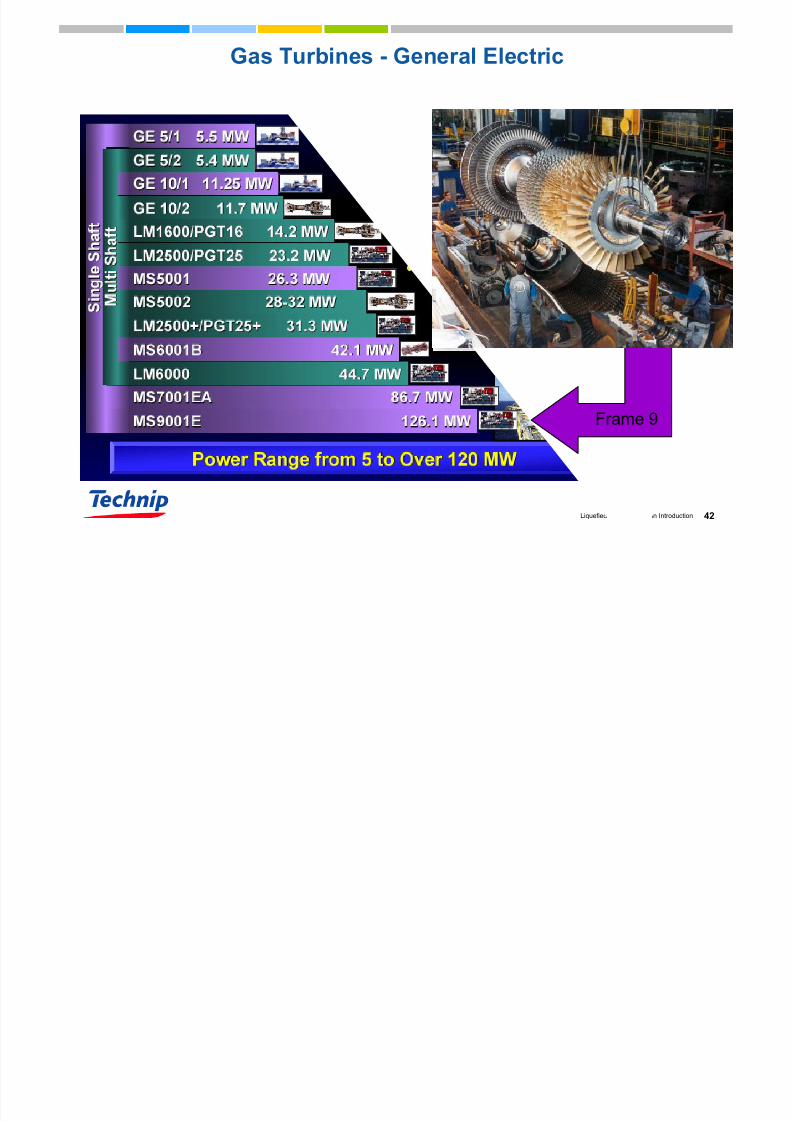
Gas Turbines - General Electric
Frame 9
Heat rejection – air and water cooling
7/23/2019 LNG an Introduction
http://slidepdf.com/reader/full/lng-an-introduction 43/60
43Liquefied Natural Gas - An Introduction
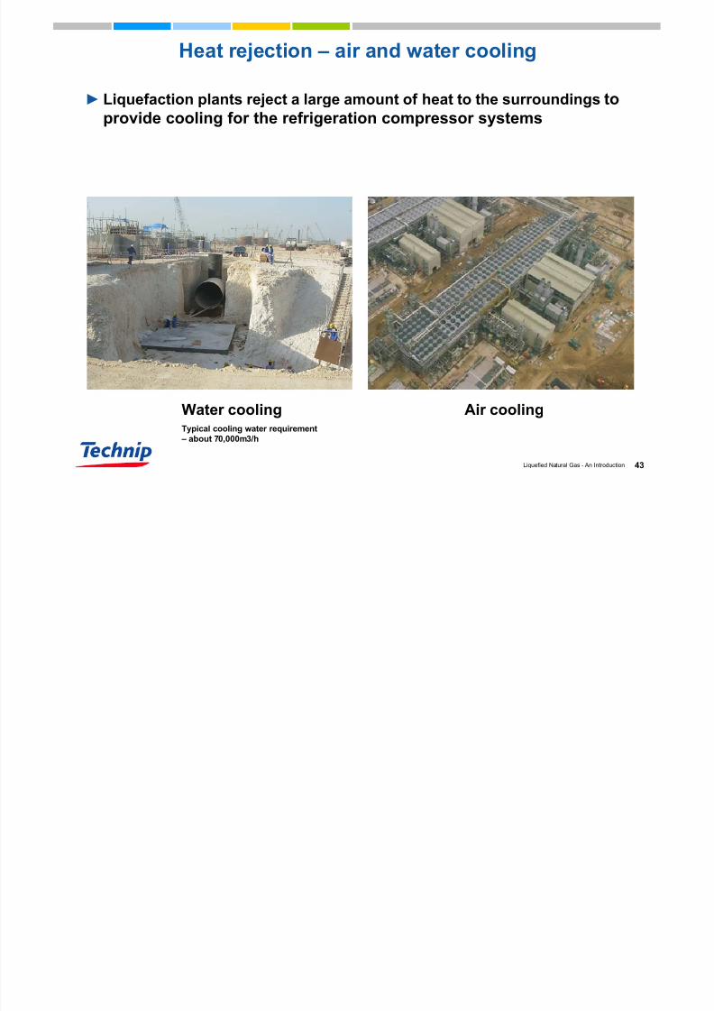
Heat rejection – air and water cooling
► Liquefaction plants reject a large amount of heat to the surroundings toprovide cooling for the refrigeration compressor systems
Water coolingTypical cooling water requirement
– about 70,000m3/h
Air cooling
Typical Utilities for LNG Production
7/23/2019 LNG an Introduction
http://slidepdf.com/reader/full/lng-an-introduction 44/60
44Liquefied Natural Gas - An Introduction
Typical Utilities for LNG Production
Electric power
• typical power requirement – about 300 MWe for 5 MMTPA LNG plant
using all motor driven refrigeration compressors,.
• Depending on Train Capacity each Refrigeration Compressor in MRC
consumes 50 to 75MW power (turbine or motor driven)
Hot water/Hot oil as heating medium in
• fractionation section, glycol regeneration, solvent recovery in acid gas
removal unit.
• Hot water generated by heat recovery from gas turbine exhaust
• Typical process demand of thermal energy from hot water is about
100MWth for a 5 MMTPA LNG plant.
►Nitrogen – high purity (99.9%) – used in refrigerant make-up
LNG STORAGE TANKS
7/23/2019 LNG an Introduction
http://slidepdf.com/reader/full/lng-an-introduction 45/60
45Liquefied Natural Gas - An Introduction
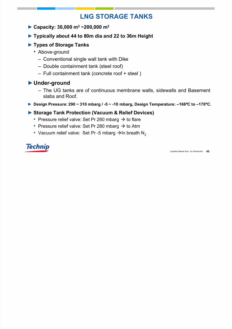
LNG STORAGE TANKS
►Capacity: 30,000 m3 ~200,000 m3
► Typically about 44 to 80m dia and 22 to 36m Height
► Types of Storage Tanks
• Above-ground
– Conventional single wall tank with Dike – Double containment tank (steel roof)
– Full containment tank (concrete roof + steel )
►Under-ground
– The UG tanks are of continuous membrane walls, sidewalls and Basementslabs and Roof.
► Design Pressure: 290 ~ 310 mbarg / -5 ~ -10 mbarg, Design Temperature: –166ºC to –170ºC.
►Storage Tank Protection (Vacuum & Relief Devices)
• Pressure relief valve: Set Pr 260 mbarg to flare
• Pressure relief valve: Set Pr 280 mbarg to Atm
• Vacuum relief valve: Set Pr -5 mbargIn breath N2
LNG STORAGE FACILITY C td
7/23/2019 LNG an Introduction
http://slidepdf.com/reader/full/lng-an-introduction 46/60
46Liquefied Natural Gas - An Introduction
►Storage Tank Selection
Criteria•Location
•Environmental considerations
•Operational conditions
•Safety and economic efficiency
LNG STORAGE FACILITY – Contd.
Full containment tankTANK DESIGN PRESSURE
TANK DESIGN PRESSURE
7/23/2019 LNG an Introduction
http://slidepdf.com/reader/full/lng-an-introduction 47/60
47Liquefied Natural Gas - An Introduction
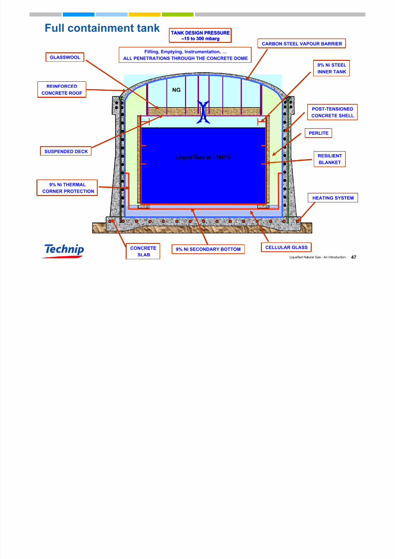
Full containment tank
Liquid Gas at –160°C
POST-TENSIONED
CONCRETE SHELL
PERLITE
RESILIENT
BLANKET
9% Ni STEEL
INNER TANK
CELLULAR GLASS
SUSPENDED DECK
GLASSWOOL
CARBON STEEL VAPOUR BARRIER
CONCRETESLAB
Filling, Emptying, Instrumentation, …ALL PENETRATIONS THROUGH THE CONCRETE DOME
9% Ni THERMAL
CORNER PROTECTION
9% Ni SECONDARY BOTTOM
TANK DESIGN PRESSURE
–15 to 300 mbarg
NG
HEATING SYSTEM
REINFORCED
CONCRETE ROOF
Liquid Gas at –160°C
POST-TENSIONED
CONCRETE SHELL
POST-TENSIONED
CONCRETE SHELL
PERLITEPERLITE
RESILIENT
BLANKET
RESILIENT
BLANKET
9% Ni STEEL
INNER TANK
9% Ni STEEL
INNER TANK
CELLULAR GLASSCELLULAR GLASS
SUSPENDED DECKSUSPENDED DECK
GLASSWOOLGLASSWOOL
CARBON STEEL VAPOUR BARRIERCARBON STEEL VAPOUR BARRIER
CONCRETESLAB
CONCRETESLAB
Filling, Emptying, Instrumentation, …ALL PENETRATIONS THROUGH THE CONCRETE DOME
9% Ni THERMAL
CORNER PROTECTION
9% Ni THERMAL
CORNER PROTECTION
9% Ni SECONDARY BOTTOM9% Ni SECONDARY BOTTOM
TANK DESIGN PRESSURE
–15 to 300 mbarg
NG
HEATING SYSTEMHEATING SYSTEM
REINFORCED
CONCRETE ROOF
REINFORCED
CONCRETE ROOF
MATERIALS OF CONSTRUCTION

7/23/2019 LNG an Introduction
http://slidepdf.com/reader/full/lng-an-introduction 48/60
48Liquefied Natural Gas - An Introduction
MATERIALS OF CONSTRUCTION
► The MOC of major/critical Equipment in Pre-cooling and liquefaction units:
• Aluminum and SS for MCHE
• Refrigeration Compressors – 3.5Ni/13Cr
• LNG Expanders – SS
• Endflash unit – SS vessels and SS pumps
• SS-316 for columns/vessels
► The MOC of major/critical Equipment in LNG storage:
• Storage tank 9% Ni Steel
• LNG Pumps: Aluminum Alloy (Casting & Impeller)
LNG IMPORT FACILITY

7/23/2019 LNG an Introduction
http://slidepdf.com/reader/full/lng-an-introduction 49/60
49Liquefied Natural Gas - An Introduction
LNG IMPORT FACILITY
Unloading Jetty
Liquid Unloading Arms & Vapour Return Arms
Liquid Unloading & Vapour return pipelines
LNG Storage tanks
Boil-off Gas (BOG) Compressor
LNG pumps (LP and HP Pumps)
LNG Vaporizers
Metering Systems for gas distribution/send-out
LNG REGASIFICATION

7/23/2019 LNG an Introduction
http://slidepdf.com/reader/full/lng-an-introduction 50/60
50Liquefied Natural Gas - An Introduction
LNG REGASIFICATION
►LIQUID PRODUCT VAPORIZED/REGASIFIED BEFORE
TRANSMISSION AND DISTRIBUTION BY PIPELINE
►PHYSICAL TRANSFORMATION FROM LIQUID STATETO GASEOUS STATE REQUIRES HEAT INPUT INTO
THE LNG
►THE VAPORIZATION EQUIPMENT ACCOMPLISHESHEAT TRANSFER IN A SAFE, EFFICIENT MANNER.
►WIDELY USED VAPORIZATION EQUIPMENT
•OPEN RACK VAPORIZER
• SUBMERGED COMBUSTION VAPORIZER
LNG REGASIFICATION – BLOCK FLOW

7/23/2019 LNG an Introduction
http://slidepdf.com/reader/full/lng-an-introduction 51/60
51Liquefied Natural Gas - An Introduction
LNG REGASIFICATION BLOCK FLOW
DIAGRAM
BOG COMPR
BOG
RECONDENSER
STORAGETANK
LNG BOOSTER
PUMP
LNG VAPORISER *
EXPORT GAS
METERINGUNLOADING
ARMS
LNG
VAP
SEA WATER
INTAKESEA WATER
DISCHARGE
TO GAS
DISTRIBUTION
PIPELINE
VAPOUR
RETURN
ARM
M
IN TANK
PUMPS
BOG Compressor
–151 to –105ºC0 – 150 mbarg
0 – 19000 Nm3/h FSRU PROCESS

7/23/2019 LNG an Introduction
http://slidepdf.com/reader/full/lng-an-introduction 52/60
52Liquefied Natural Gas - An Introduction
– 145 to –
150ºC3 – 6 Barg
PROPANE
DRUM
Vapour Return Arm
LNGUnloading Arms
Hybrid Arm M
TO VENT MAST
M
HP Send Out Pump
Metering
To 32”
Subsea Pipeline
(via turret,
PLEM)
Intermediate Fluid
Vaporiser
Sea water from power plant
turbine condenser
Sea water
return
LNG Storage Tanks
(MOSS Spheres)
4 x 34250 m3
Recondenser
Natural Gas
0ºC; 84 Barg
14.7 MMSCMD
5.37 BCM/Yr
– 155ºC87 Barg
– 30 to 0ºC3 – 6 Barg
– 1 6 0 . 5
º C
6 - 7 B a r g
(NET BOG)
SCHEMATIC
– 157ºC
2 Barg12,000 m3 /h
LNG Vaporizers

7/23/2019 LNG an Introduction
http://slidepdf.com/reader/full/lng-an-introduction 53/60
53Liquefied Natural Gas - An Introduction
LNG Vaporizers
LNG re-gasified in vaporizing units by heating,through heat exchange with seawater or byburning gas.
Open-Rack type LNG Vaporizer (ORV) uses seawater as the heat source.
Submerged Combustion Vaporizer (SCV) uses NG
as the heat sourceSCV used when ORV is under maintenance or for
peak shaving.
Multiple ORVs and only one SCV are used.
SCV capacity is generally 15 to 25% of ORVcapacity.
Open-Rack Vaporizer

7/23/2019 LNG an Introduction
http://slidepdf.com/reader/full/lng-an-introduction 54/60
54Liquefied Natural Gas - An Introduction
Open Rack Vaporizer
ORV composed of panel-shaped heat transfer tubesmade of aluminum alloy.
LNG flows upward inside the finned heat transfer tubes,sea water flows down along the outer surfaces of the
tubes. Performance Improvement and reduction of sea water
flow rate for conventional ORVs are limited due to iceformation on the outer surface of heat transfer tubes.
Approx. sea water requirement: 32 m3 /ton LNGevaporated at 5ºC T
To protect the ORV against corrosion by seawater, analuminum-zinc alloy is thermal-sprayed on the panels andupper and lower headers exposed to seawater.
Open-Rack Vaporizer

7/23/2019 LNG an Introduction
http://slidepdf.com/reader/full/lng-an-introduction 55/60
55Liquefied Natural Gas - An Introduction

7/23/2019 LNG an Introduction
http://slidepdf.com/reader/full/lng-an-introduction 56/60
56Liquefied Natural Gas - An Introduction
Submerged Combustion Vaporizer

7/23/2019 LNG an Introduction
http://slidepdf.com/reader/full/lng-an-introduction 57/60
57Liquefied Natural Gas - An Introduction
Distribution Facility

7/23/2019 LNG an Introduction
http://slidepdf.com/reader/full/lng-an-introduction 58/60
58Liquefied Natural Gas - An Introduction
►Gas Distribution by Pipeline
• Power Plants
• Petrochemical/Fertilizer Plants• Heavy/Light Industries (Steel/Automobile)
• City Domestic Consumption
►Liquid Distribution by Road Tanker
• Small Consumers• Remote Housing Facility
SUCCESS OF AN LNG PLANT DEPENDS ON

7/23/2019 LNG an Introduction
http://slidepdf.com/reader/full/lng-an-introduction 59/60
59Liquefied Natural Gas - An Introduction
►STRONG THERMODYNAMIC
FUNDAMENTALS
►SOUND ENGINEERING
PRACTICES
►WELL DEFINED EVALUATION
CRITERIA

7/23/2019 LNG an Introduction
http://slidepdf.com/reader/full/lng-an-introduction 60/60
60Liquefied Natural Gas - An Introduction
Thank you
for
your attention


