32
3rd Edition (57.7) CI/SfB (57.7) CI/SfB +LJK (IÀFLHQF\ 09+5 &RRNHU +RRG 8QLWV Lo-Carbon Sentinel Kinetic Range
3rd Edition(57.7)CI/SfB
(57.7)CI/SfB
Lo-Carbon Sentinel Kinetic Range
2 T: 0844 856 0590
Features & Benefits
• Manufactured in the UK
• Building Regulations ADF and ADL compliant
• Recognised in SAP Appendix Q
• Specific Fan Power down to 0.4 W/l/s
• Up to 94% heat recovery
• Fully automatic Summer bypass
• Horizontal and/or vertical duct outlets
• Integrated digital controller for simple and accurate commissioning
• Lightweight for easy installation
• External condensate connection
• Plug and play controls; Humidistat, Ventwise, Wireless Remote
• BMS connectivity
• LS inputs (Light Switch)
• Volt-free inputs
• Self diagnosis for simplified fault finding
• Adjustable delay On/delay Off timer
• 0V to 10V proportional inputs
• Enthalpy heat recovery option
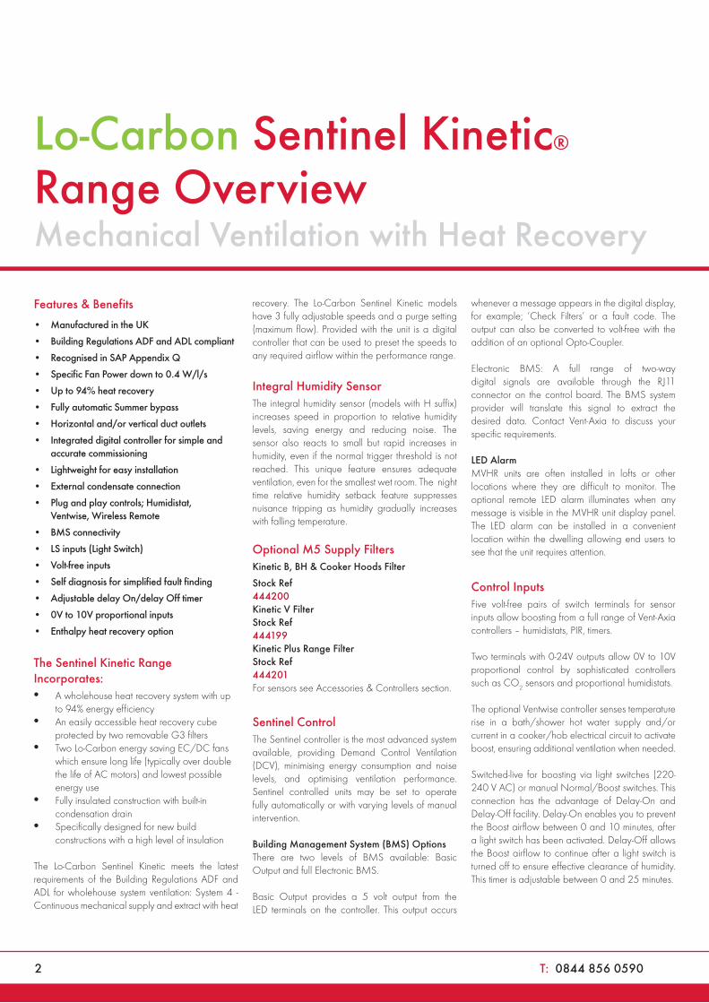
The Sentinel Kinetic Range Incorporates:• A wholehouse heat recovery system with up
to 94% energy efficiency • An easily accessible heat recovery cube
protected by two removable G3 filters• Two Lo-Carbon energy saving EC/DC fans
which ensure long life (typically over double the life of AC motors) and lowest possible energy use
• Fully insulated construction with built-in condensation drain
• Specifically designed for new build constructions with a high level of insulation
The Lo-Carbon Sentinel Kinetic meets the latest requirements of the Building Regulations ADF and ADL for wholehouse system ventilation: System 4 - Continuous mechanical supply and extract with heat
recovery. The Lo-Carbon Sentinel Kinetic models have 3 fully adjustable speeds and a purge setting (maximum flow). Provided with the unit is a digital controller that can be used to preset the speeds to any required airflow within the performance range.
Integral Humidity SensorThe integral humidity sensor (models with H suffix) increases speed in proportion to relative humidity levels, saving energy and reducing noise. The sensor also reacts to small but rapid increases in humidity, even if the normal trigger threshold is not reached. This unique feature ensures adequate ventilation, even for the smallest wet room. The night time relative humidity setback feature suppresses nuisance tripping as humidity gradually increases with falling temperature.
Optional M5 Supply Filters
Kinetic B, BH & Cooker Hoods Filter
Stock Ref £Trade444200 21.78Kinetic V Filter Stock Ref £Trade444199 21.78Kinetic Plus Range Filter Stock Ref £Trade444201 32.98For sensors see Accessories & Controllers section.
Sentinel ControlThe Sentinel controller is the most advanced system available, providing Demand Control Ventilation (DCV), minimising energy consumption and noise levels, and optimising ventilation performance. Sentinel controlled units may be set to operate fully automatically or with varying levels of manual intervention.
Building Management System (BMS) OptionsThere are two levels of BMS available: Basic Output and full Electronic BMS.
Basic Output provides a 5 volt output from the LED terminals on the controller. This output occurs
whenever a message appears in the digital display, for example; ‘Check Filters’ or a fault code. The output can also be converted to volt-free with the addition of an optional Opto-Coupler.
Electronic BMS: A full range of two-way digital signals are available through the RJ11 connector on the control board. The BMS system provider will translate this signal to extract the desired data. Contact Vent-Axia to discuss your specific requirements.
LED AlarmMVHR units are often installed in lofts or other locations where they are difficult to monitor. The optional remote LED alarm illuminates when any message is visible in the MVHR unit display panel. The LED alarm can be installed in a convenient location within the dwelling allowing end users to see that the unit requires attention.
Control InputsFive volt-free pairs of switch terminals for sensor inputs allow boosting from a full range of Vent-Axia controllers – humidistats, PIR, timers.
Two terminals with 0-24V outputs allow 0V to 10V proportional control by sophisticated controllers such as CO2 sensors and proportional humidistats.
The optional Ventwise controller senses temperature rise in a bath/shower hot water supply and/or current in a cooker/hob electrical circuit to activate boost, ensuring additional ventilation when needed.
Switched-live for boosting via light switches (220-240 V AC) or manual Normal/Boost switches. This connection has the advantage of Delay-On and Delay-Off facility. Delay-On enables you to prevent the Boost airflow between 0 and 10 minutes, after a light switch has been activated. Delay-Off allows the Boost airflow to continue after a light switch is turned off to ensure effective clearance of humidity. This timer is adjustable between 0 and 25 minutes.
Lo-Carbon Sentinel Kinetic®
Range OverviewMechanical Ventilation with Heat Recovery
W: www.vent-axia.com/mvhr 3
MVHR Units
The units can be boosted incrementally via the on-board controller or the Wired Remote Controller: One press = 30 minutes, two presses = 60 minutes, three presses = continuous.
Optional Controls CAS
LED Alarm with 15 metre cableStock Ref £Trade448356 29.16
Wired Remote Controller with 15 metre cable Stock Ref £Trade443283 54.01
Wireless Enable Kit (includes one switch) Stock Ref £Trade441865 81.02
Additional Wireless Boost Switch (max 3 switches) Stock Ref £Trade437827 50.11
Ventwise Controller (also requires sensors, see Accessories & Controllers section) Stock Ref £Trade441780 182.28
Purge settingThe unit can be set to maximum flow (100%) by pressing and holding the Boost button on the unit itself or optional wired controller for 5 seconds. Purge will continue for two hours unless cancelled by pressing the Boost button again.
Summer Bypass An internal damper operates when the external temperature is below the internal temperature, and the internal temperature is too high.
The bypass opens and allows the cooler outside air to help cool the dwelling.
Normal mode: Fans run on Normal speed with bypass open until the internal dwelling temperature falls below the set 'Indoor' (maximum desired) temperature.
Evening Purge mode: The fans run on Boost speed until the internal temperature falls below the set 'Indoor' temperature. If, after five hours the internal temperature is still above the set 'Indoor' temperature, the unit will switch down to normal speed for the remainder of the 'bypass open' period.
Night-time Purge mode: As Evening Purge, except that the unit will continue on Boost speed until the internal air temperature reaches the 'Outdoor' temperature set point (Default 14°C). This mode gives pre-cooling of the dwelling for the following day.
In Evening and Night Time Purge modes, the user can turn off the boost function by pressing the Boost button.
Frost Protection In order to prevent frost forming inside the unit in winter conditions, the Kinetic range employs a sophisticated frost protection strategy that modifies the airflows ensuring heat recovery continues down to -20°C. Below this temperature, the units will operate as 'extract only' fans. If balanced ventilation is required at low temperatures, a duct pre-heater should be used.
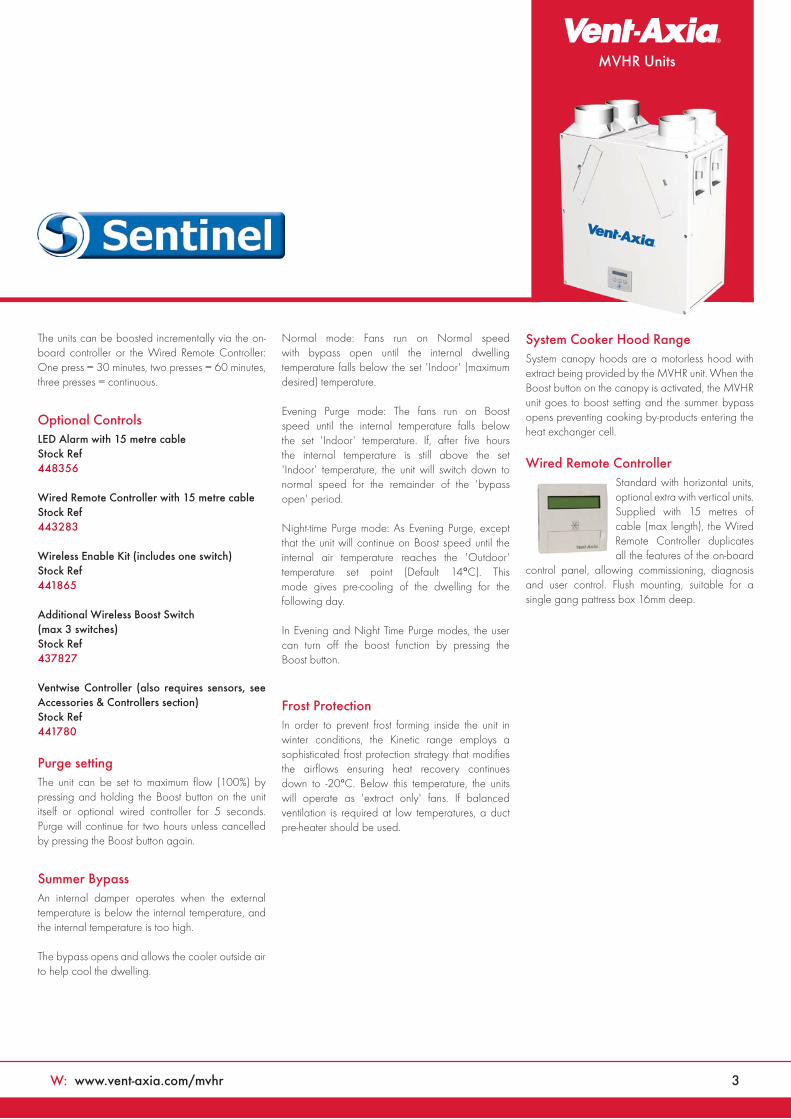
System Cooker Hood RangeSystem canopy hoods are a motorless hood with extract being provided by the MVHR unit. When the Boost button on the canopy is activated, the MVHR unit goes to boost setting and the summer bypass opens preventing cooking by-products entering the heat exchanger cell.
Wired Remote Controller Standard with horizontal units, optional extra with vertical units. Supplied with 15 metres of cable (max length), the Wired Remote Controller duplicates all the features of the on-board
control panel, allowing commissioning, diagnosis and user control. Flush mounting, suitable for a single gang pattress box 16mm deep.

4 T: 0844 856 0590
Lo-CarbonKinetic® Range OverviewMechanical Ventilation with Heat Recovery
Model Range Overiew
Sentinel Kinetic Range Kinetic E Range
Model Ranges
Lo-Carbon Sentinel
Kinetic Plus
Lo-Carbon Sentinel
Kinetic Cooker Hood
Lo-Carbon
Sentinel Kinetic
Lo-Carbon
Sentinel Kinetic Horizontal
Lo-Carbon
Kinetic Plus E
Lo-Carbon
Kinetic E
Models Plus C CH V B BH 200ZP/ZPH 300Z/ZH 200Z/ZH Plus E E
Auto Summer Bypass
Easy Access Filters
Very Low Noise Levels
Integral Cooker Hood
Built-In Humidistat
Kitchen Cupboard Inst’n
Max Airflow @ 100Pa 117 68 68 68 68 68 34 81 50 117 36
Frost Protection
Delay-On
Wired Remote Control O O O O O O
Wireless Boost O O O O O O O O O
Clean Filter Indicator (Time)
Fault Code Indicator
Potentiometer Control
Sentinel Control
Switched Live
No Volt Contact
0V - 10V Proportional Control
BMS Input/Output 1 1 1 1 1 1 1 1 1
Lightweight
External Condensate
Horizontal Duct Option
Horizontal (Slab) Installation
Left/Right Orientation
Ventwise Control
PIN Number Lock
Running Time Indicator
Pre-Heater Controller O O O O O O O O O
Enthalpy Heater Exchanger O O O
Mounting Options
Wall Surface Wall Wall Surface Slab Wall Surface Wall Surface
O - Denote Optional, 1- Seek technical advice from Vent-Axia
W: www.vent-axia.com/mvhr 5
MVHR Units
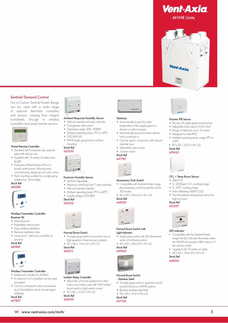
Sentinel Demand ControlThe Lo-Carbon Sentinel Kinetic Range can be used with a wide range of optional Vent-Axia controllers and sensors, ranging from integral humidistats, through to wireless controllers and wired remote sensors.
Wired Remote Controller DOM
• Standard with horizontal units, optional extra with vertical units
• Supplied with 15 metres of cable (max length)
• Duplicates all the features of the on-board control panel, allowing easy commissioning, diagnosis and user control
• Flush mounting, suitable for a single gang pattress box 16mm deep
Stock Ref £ Trade443283 54.01
Wireless Transmitter Controller Receiver Kit DOM
• Manual boost • Adjustable overrun timer • Easy wireless installation• Reduces installation time• Future proof - add more controllers at
any time Stock Ref £ Trade441865 81.02
Wireless Transmitter Controller CAS
• Additional controller for 441865• A maximum of 4 controllers can be used
per system• Can be connected to other accessories
(e.g. Humidistat) to send a boost signal wirelessly
Stock Ref £ Trade437827 50.11
Ambient Response Humidity Sensor GEN
• Pullcord override and neon indicator• Changeover relay switch• Operating range: 30% - 90%RH• Ambient operating temp. 5°C to 40°C• 220-240V AC• Will fit single gang box for surface
mountingStock Ref £ Trade563550 189.30
Ecotronic Humidity Sensor GEN
• Set Point adjustable• Maximum switching load 1 amp inductive• Pullcord override indicator• Ambient operating temp. 0°C to 40°C• Supply voltage 220-240VStock Ref £ Trade563532 103.16
Normal Boost Switch GEN
• A single gang switch to boost from low to high speeds on heat recovery systems
• 85 x 85 x 10mm (H x W x D)Stock Ref £ Trade 455213 35.45
Isolator Relay Controller CAS
• Allows fan unit to be isolated from other mains circuit when used with TIM2 trickle/boost switch or light switch control
• 87 x 87 x 33 (H x W x D)Stock Ref £ Trade442030 60.76
Ventwise CAS
• Automatically boosts fan when temperature of the supply pipe to a shower or bath increases
• Automatically boosts fan when electric hob is switched on
• Can be used in conjunction with manual override input
• Adjustable overrun timer• 3 sensor inputsStock Ref £ Trade441780 182.28
Momentary Push Switch• Compatible with Sentinel Kinetic range,
the momentary switch boosts the unit for 30 minutes
• 85 x 85 x 10mm (H x W x D)Stock Ref £ Trade 448929 18.54
Normal Boost Switch with Light Indicator GEN
• Single gang switch with LED illumination when in the Boost position
• 85 x 85 x 10mm (H x W x D)Stock Ref £ Trade 449060 35.45
Normal Boost Switch - Stainless Steel CAS
• A single gang switch to operate normal/boost functions on MVHR systems
• Brushed stainless steel finish• 90 x 90 x 18 (H x W x D)Stock Ref £ Trade 437320 43.20
Visonex PIR Sensor GEN
• Fits any UK single gang mounting box• Adjustable timer overrun (5-25 mins)• Range of detection up to 10 metres• Designed to meet IP43• Ambient operating temp. range 0°C to
50°C• 87 x 87 x 33 (H x W x D)Stock Ref £ Trade459623 106.98
CO2 + Temp Room Sensor IND
• 240V DC• 0 - 2000ppm CO2 working range• 0 - 50°C working range• Auto-calibrating NDIR CO22• Thin film platinum temperature sensor for
high accuracyStock Ref £ Trade 433257 533.95
LED Indicator• Compatible with the Sentinel Kinetic
range, the LED indicator illuminates when the MVHR unit requires a filter check or if the unit has a fault
• Supplied with 15 metres of cable• 85 x 85 x 10mm (H x W x D)Stock Ref £ Trade448356 29.16
6 T: 0844 856 0590
Lo-CarbonSentinel Kinetic®
MVHR Units
Features & Benefits
• Recognised in SAP Appendix Q
• Ultra quiet
• Lightweight for easier installation
• Horizontal duct option for space-saving installations
• Fits within a 290mm deep kitchen cupboard
• Integrated digital controller for simple and accurate commissioning
• Plug and play controls; Humidistat, Ventwise, Wireless Remote
• BMS connectivity
• LS inputs (Light Switch)
• Volt-free inputs
• Self diagnosis for simplified fault finding
• Adjustable delay On/delay Off timer
Easy InstallationThe Sentinel Kinetic models can be mounted vertically in a roof space, hallway cupboard or kitchen or within a kitchen cupboard. When mounted in an unheated area ducting should be insulated. Ducting can be attached to the unit horizontally, vertically or both. Minimum internal depth of kitchen cupboard: V, B & BH models 290mm.
Left (L) or right (R) hand installation. The unit is supplied with duct spigots to outside on the right hand side. These can be reversed on site by simply removing the control panel, rotating the unit 180 degrees and re-attaching the control panel.
Spigot OptionsThe combination of spigot options allows installation in confined locations. If vertical and horizontal connection is required on the same outlet/inlet, additional spigots can be supplied.
The condensate drain can be taken out through the back, side or bottom of the unit. Using the fittings supplied, the final condensate connection is made outside the unit and can be completed after installation.
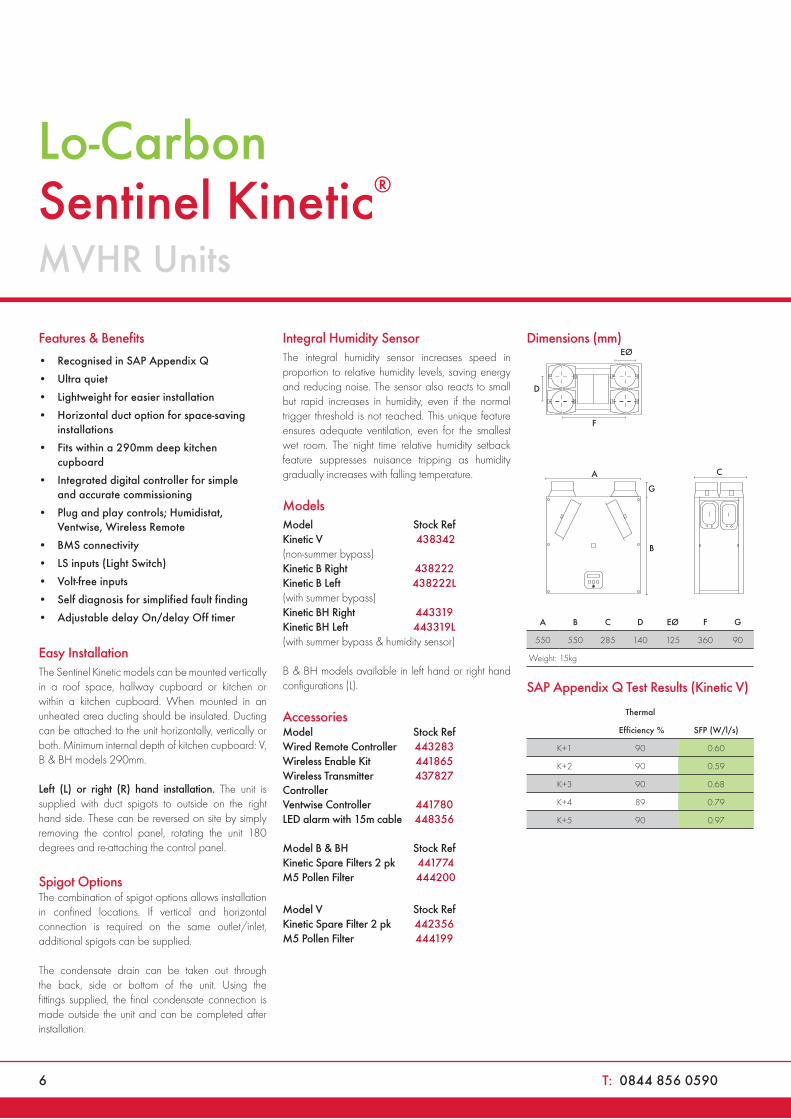
Integral Humidity SensorThe integral humidity sensor increases speed in proportion to relative humidity levels, saving energy and reducing noise. The sensor also reacts to small but rapid increases in humidity, even if the normal trigger threshold is not reached. This unique feature ensures adequate ventilation, even for the smallest wet room. The night time relative humidity setback feature suppresses nuisance tripping as humidity gradually increases with falling temperature.
Models CAS
Model Stock Ref £TradeKinetic V 438342 1262.49(non-summer bypass) Kinetic B Right 438222 1343.51Kinetic B Left 438222L 0.00(with summer bypass) Kinetic BH Right 443319 1424.52Kinetic BH Left 443319L 0.00(with summer bypass & humidity sensor)
B & BH models available in left hand or right hand configurations (L).
Accessories CAS
Model Stock Ref £TradeWired Remote Controller 443283 54.01Wireless Enable Kit 441865 81.02Wireless Transmitter 437827 50.11ControllerVentwise Controller 441780 182.28LED alarm with 15m cable 448356 29.16
Model B & BH Stock Ref £TradeKinetic Spare Filters 2 pk 441774 21.78M5 Pollen Filter 444200 21.78
Model V Stock Ref £TradeKinetic Spare Filter 2 pk 442356 21.78M5 Pollen Filter 444199 21.78
Dimensions (mm)
G
C
D
B
EØ
F
A
A B C D EØ F G
550 550 285 140 125 360 90
Weight: 15kg
SAP Appendix Q Test Results (Kinetic V)
Thermal
Efficiency % SFP (W/l/s)
K+1 90 0.60
K+2 90 0.59
K+3 90 0.68
K+4 89 0.79
K+5 90 0.97
W: www.vent-axia.com/mvhr 7
MVHR Units
Example system curves -
vertical spigots
Example system curves -
horizontal spigots
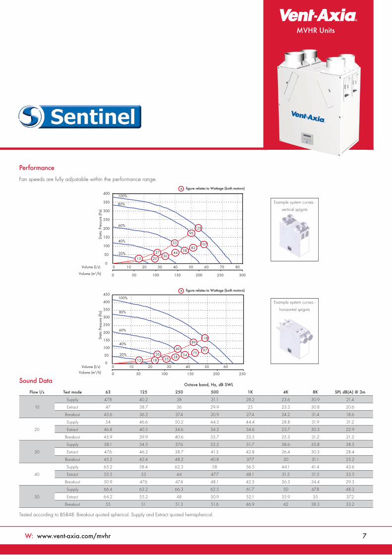
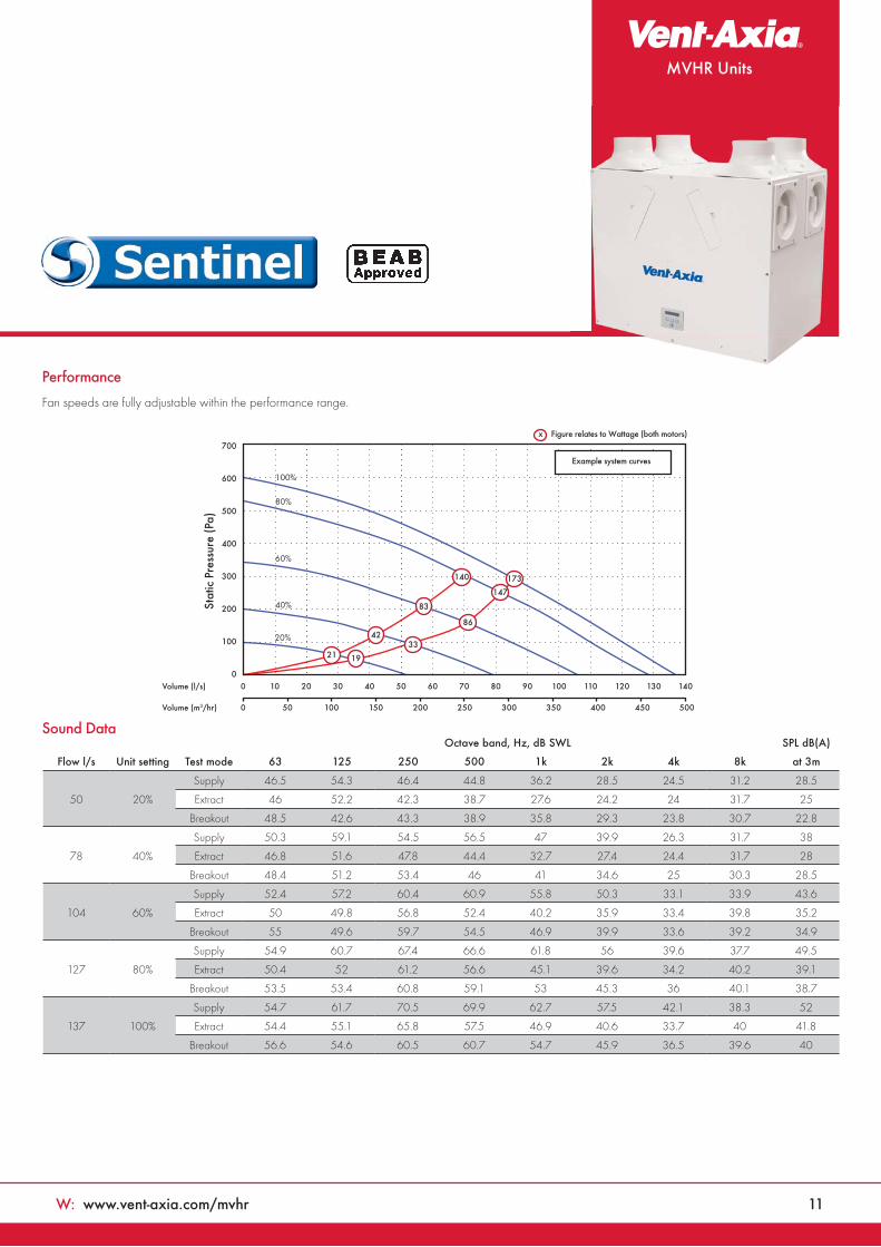
Performance
Fan speeds are fully adjustable within the performance range.
Sound Data
Tested according to BS848. Breakout quoted spherical. Supply and Extract quoted hemispherical.
0
50
100
150
200
250
300
350
400
450
Stat
ic P
ress
ure
(Pa)
20%
40%
60%
80%
100%
0
50
100
150
200
250
300
350
400
Stat
ic P
ress
ure
(Pa)
00 10 20 30 40 50 60 70 80
0 10 20 30 40 50 60
0 50 100 150 200 250
0 50 100 150 200 250 300
53
27
2030
44
128
107
20%
40%
60%
80%
100%
Volume (m3/h)
Volume (l/s)
Volume (m3/h)
Volume (l/s)
13
96
8258
x figure relates to Wattage (both motors)
x figure relates to Wattage (both motors)
12
4926
18 25 38
118
97
89
7554
Octave band, Hz, dB SWL
Flow l/s Test mode 63 125 250 500 1K 4K 8K SPL dB(A) @ 3m
10
Supply 47.8 40.2 38 31.1 28.2 23.6 30.9 21.4
Extract 47 38.7 36 29.9 25 23.3 30.8 20.6
Breakout 43.6 36.2 37.4 30.9 27.4 24.2 31.4 18.6
20
Supply 54 46.6 50.2 44.5 44.4 28.8 31.9 31.2
Extract 46.8 40.5 34.6 34.2 34.6 23.7 30.3 22.9
Breakout 45.9 39.9 40.6 35.7 33.5 25.3 31.2 21.3
30
Supply 58.1 54.5 57.6 52.2 51.7 38.6 35.8 38.5
Extract 47.6 46.2 38.7 41.3 42.8 26.4 30.5 28.4
Breakout 45.2 42.4 48.2 40.8 37.7 30 31.1 25.2
40
Supply 65.2 58.4 62.3 58 56.5 44.1 41.4 43.6
Extract 53.5 53 44 47.7 48.1 31.5 31.5 33.5
Breakout 50.9 47.6 47.4 48.1 42.5 36.3 34.4 29.3
50
Supply 66.4 63.2 66.3 62.5 61.7 50 47.8 48.3
Extract 64.2 55.2 48 50.9 52.1 35.9 35 37.2
Breakout 55 51 51.3 51.6 46.9 42 38.3 33.2
8 T: 0844 856 0590
Lo-Carbon Sentinel® Kinetic
Consultant's Specification
Operation The supply and extract ventilation unit shall be a Sentinel Kinetic as manufactured by Vent-Axia and shall be sized as indicated on the drawings and shall be in accordance with the particular specification.
Supply air to the room shall be pre-heated by the extract air via the integrated composite plastic counterflow heat recovery cell. The Sentinel Kinetic shall automatically vary the ventilation rate via EC/DC motors, as it receives signals from one of the optional interconnected sensors. When a signal is received, the fans shall either vary their speed proportionally or on a trickle and boost principle.
The unit shall have the facility to commission the supply and extract fans individually via in-built minimum and maximum speed adjustment, or alternative wired remote control unit. The fans themselves shall have independent, infinitely variable speed control.
Unit specificationThe unit shall be manufactured with an ABS outer case construction, and incorporate a reversible core to allow for left or right hand mounting.
The unit shall have a high efficiency composite plastic counterflow heat exchanger, supply and extract filters, automatic summer bypass, (B/BH) integral minimum and maximum infinitely variable speed controls with facia mounted failure indication. The unit shall have low energy, high efficiency EC/DC fan/motor assemblies with sealed for life bearings. The impellers shall be high efficiency forward curved centrifugal type.
The unit shall have a heat exchanger cell with a thermal efficiency of up to 92% when tested to EN 308. This shall be protected by G3 grade synthetic filters on supply and extract. Complete with a condensate drip tray and drain connection.
The unit shall be constructed with a removable Core allowing full maintenance access. The removable Core shall provide access to the following:
Supply and extract filter Heat exchanger Access to the electrical connections
Access shall be provided for wiring termination and setup/commissioning. The backlit LCD user interface therein shall be removable for remote mounting if required.
Units shall be as manufactured by Vent-Axia Ltd.
Standard controlsAll Sentinel Kinetic units shall incorporate the following functions integrally mounted, pre-wired and factory fitted by the manufacturer:
Integral infinitely variable fan speed control on supply and extract
Integral min/max ventilation control/set point Integral BMS interfaces – control and status
indication Heating interlocks 0-10V proportional speed adjustment Volt free contacts 24V sensor supply Integral on/off or trickle boost function from
remote switch e.g. PIR occupancy detector The unit shall be controlled by the ‘Sentinel’
control devices (enablers and sensors) as detailed in the schedule or on the drawings
Fully automatic summer bypass Switched Live input with adjustable ‘delay-on’
feature Fan failure or component failure indicated via
individual fault code display Running time counter Control panel PIN number lock Automatic frost protection effective to -20°C Tool free filter access
The unit shall incorporate (‘H’ models) an integral humidity sensor with the following features:
• Ambient Response; Raises the humidity trigger point as dwelling temperature reduces
• Rapid Response; Monitors the rate of change in humidity and triggers increased airflow even if the humidity trigger threshold is not reached
• Proportional Response; Incrementally increases the fan speed to reduce noise and reduce energy consumption
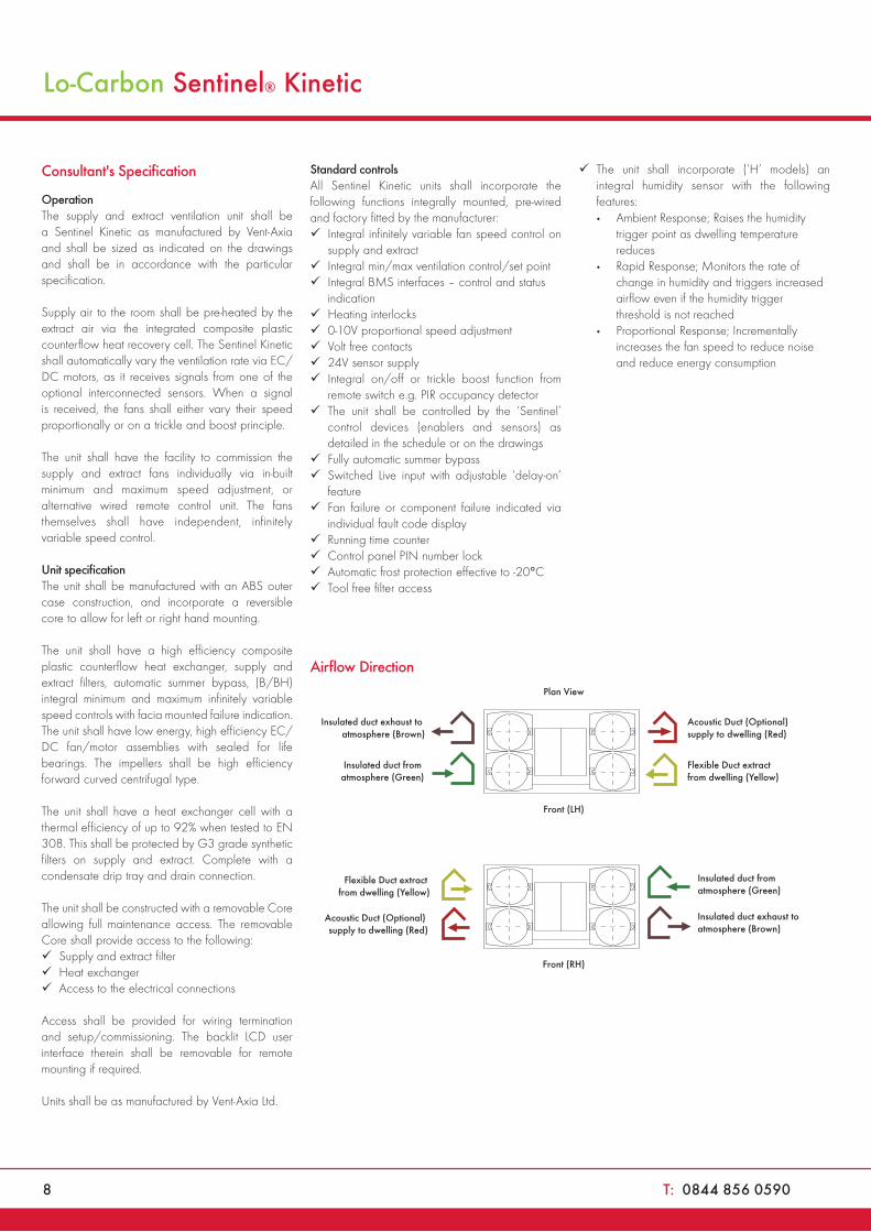
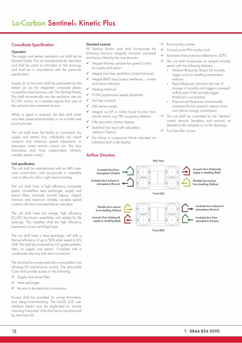
Airflow Direction
Flexible Duct extract from dwelling (Yellow)
Acoustic Duct (Optional) supply to dwelling (Red)
Insulated duct from atmosphere (Green)
Insulated duct exhaust to atmosphere (Brown)
Front (RH)
Flexible Duct extract from dwelling (Yellow)
Acoustic Duct (Optional) supply to dwelling (Red)
Insulated duct from atmosphere (Green)
Insulated duct exhaust to atmosphere (Brown)
Front (LH)
Plan View
MVHR Units
W: www.vent-axia.com/mvhr 9
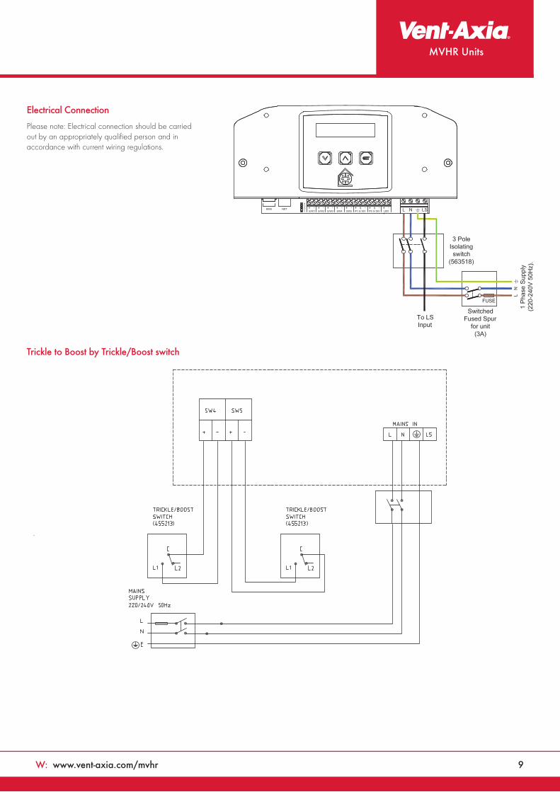
Trickle to Boost by Trickle/Boost switch
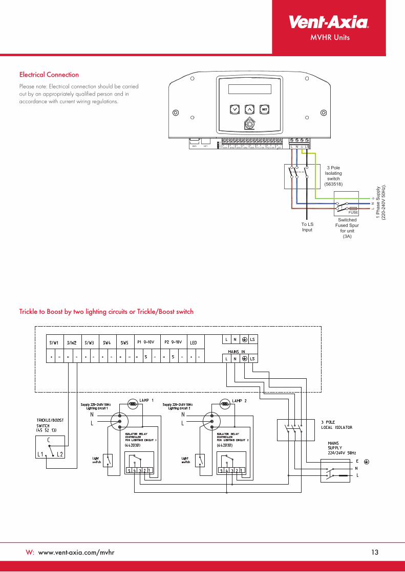
Electrical Connection
Please note: Electrical connection should be carried out by an appropriately qualified person and in accordance with current wiring regulations.
10 T: 0844 856 0590
Lo-CarbonSentinel Kinetic® PlusMVHR Unit
Features & Benefits
• Recognised in SAP Appendix Q
• Ultra quiet
• Horizontal duct option for space-saving installations
• High airflow, ideal for student accommodation clusters
• Unique folding filter for removal when access is restricted
• Integrated digital controller for simple and accurate commissioning
• Lightweight for easy installation
• Plug and play controls; Humidistat, Ventwise, Wireless Remote
• BMS connectivity
• LS inputs (Light Switch)
• Volt-free inputs
• Self diagnosis for simplified fault finding
• Adjustable delay On/delay Off timer
• Summer bypass and frost protection
Increased PerformanceThe Sentinel Kinetic Plus benefits from the latest high efficiency, backward curved impeller design, ensuring the lowest possible energy consumption, ultra quiet operation and an exceptional performance range covering small one bed apartments to the largest of houses.
Care Homes & Student AccommodationThe Sentinel Kinetic Plus is ideal for larger homes and multiple occupancy units such as care homes and student accommodation. Capable of 400m3/hr at 150Pa, the unit can extract from up to ten bathrooms and a communal kitchen while still achieving almost 90% heat recovery. The fully automatic capability of the Kinetic range means that adequate ventilation is always achieved.
The Kinetic’s BMS capability is also ideal for those commercial applications where landlords or property managers want to monitor and optimise building performance and maintenance. The Kinetic BMS can provide status information and its self diagnostics can report if any fault is found.
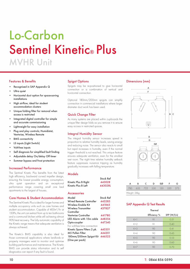
Spigot OptionsSpigots may be re-positioned to give horizontal connection or a combination of vertical and horizontal connection.
Optional 180mm/200mm spigots can simplify connection in commercial installations where larger diameter duct work has been used.
Quick Change FilterAs many systems are placed within cupboards the unique filter design folds as you remove it to ensure easy access in restricted spaces.
Integral Humidity SensorThe integral humidity sensor increases speed in proportion to relative humidity levels, saving energy and reducing noise. The sensor also reacts to small but rapid increases in humidity, even if the normal trigger threshold is not reached. This unique feature ensures adequate ventilation, even for the smallest wet room. The night time relative humidity setback feature suppresses nuisance tripping as humidity gradually increases with falling temperature.
Models CAS
Stock Ref £TradeKinetic Plus B Right 443028 1586.55Kinetic Plus B Left 443028L 1586.55
Accessories CAS
Model Stock Ref £TradeWired Remote Controller 443283 54.01Wireless Enable Kit 441865 81.02Wireless Transmitter 437827 50.11Controller Ventwise Controller 441780 182.28LED Alarm with 15m cable 448356 29.16Opto-coupler 447340 34.99For volt-free bms connectionKinetic Spare Filters 2 pk. 443351 34.62M5 Pollen Filter 444201 32.98180mm/200mm Spigot Kit 446523 8.58(One per pack)
Dimensions (mm)
A B C D EØ F G
785 635 722 550 150 520 275
Weight: 24kg
SAP Appendix Q Test Results
Thermal
Efficiency % SFP (W/l/s)
K+1 91 0.51
K+2 91 0.40
K+3 90 0.41
K+4 90 0.45
K+5 90 0.53
K+6 90 0.60
K+7 90 0.70
W: www.vent-axia.com/mvhr 11
MVHR Units
Volume (l/s) 0 10 20 30 40 50 60 70 80 90 100 110 120 130 140
Volume (m3/hr) 0 50 100 150 200 250 300 350 400 450 500
700
600
500
400
300
200
100
0
Example system curves
x Figure relates to Wattage (both motors)
21
42
83
140 173
147
86
33
19
Stat
ic P
ress
ure
(Pa)
100%
80%
60%
40%
20%
Sound Data
Performance
Fan speeds are fully adjustable within the performance range.
Octave band, Hz, dB SWL SPL dB(A)
Flow l/s Unit setting Test mode 63 125 250 500 1k 2k 4k 8k at 3m
50 20%
Supply 46.5 54.3 46.4 44.8 36.2 28.5 24.5 31.2 28.5
Extract 46 52.2 42.3 38.7 27.6 24.2 24 31.7 25
Breakout 48.5 42.6 43.3 38.9 35.8 29.3 23.8 30.7 22.8
78 40%
Supply 50.3 59.1 54.5 56.5 47 39.9 26.3 31.7 38
Extract 46.8 51.6 47.8 44.4 32.7 27.4 24.4 31.7 28
Breakout 48.4 51.2 53.4 46 41 34.6 25 30.3 28.5
104 60%
Supply 52.4 57.2 60.4 60.9 55.8 50.3 33.1 33.9 43.6
Extract 50 49.8 56.8 52.4 40.2 35.9 33.4 39.8 35.2
Breakout 55 49.6 59.7 54.5 46.9 39.9 33.6 39.2 34.9
127 80%
Supply 54.9 60.7 67.4 66.6 61.8 56 39.6 37.7 49.5
Extract 50.4 52 61.2 56.6 45.1 39.6 34.2 40.2 39.1
Breakout 53.5 53.4 60.8 59.1 53 45.3 36 40.1 38.7
137 100%
Supply 54.7 61.7 70.5 69.9 62.7 57.5 42.1 38.3 52
Extract 54.4 55.1 65.8 57.5 46.9 40.6 33.7 40 41.8
Breakout 56.6 54.6 60.5 60.7 54.7 45.9 36.5 39.6 40
12 T: 0844 856 0590
Consultants Specification
OperationThe supply and extract ventilation unit shall be as Sentinel Kinetic Plus as manufactured by Vent-Axia and shall be sized as indicated on the drawings and shall be in accordance with the particular specification.
Supply air to the room shall be pre-heated by the extract air via the integrated composite plastic counterflow heat recovery cell. The Sentinel Kinetic Plus shall automatically vary the ventilation rate via EC/DC motors, as it receives signals from one of the optional interconnected sensors.
When a signal is received, the fans shall either vary their speed proportionally or on a trickle and boost principle.
The unit shall have the facility to commission the supply and extract fans individually via in-built minimum and maximum speed adjustment, or alternative wired remote control unit. The fans themselves shall have independent, infinitely variable speed control.
Unit specificationThe unit shall be manufactured with an ABS outer case construction, and incorporate a reversible core to allow for left or right hand mounting.
The unit shall have a high efficiency composite plastic counterflow heat exchanger, supply and extract filters, automatic summer bypass, integral minimum and maximum infinitely variable speed controls with facia mounted failure indication.
The unit shall have low energy, high efficiency EC/DC fan/motor assemblies with sealed for life bearings. The impellers shall be high efficiency backward curved centrifugal type.
The unit shall have a heat exchanger cell with a thermal efficiency of up to 92% when tested to EN 308. This shall be protected by G3 grade synthetic filters on supply and extract. Complete with a condensate drip tray and drain connection.
The unit shall be constructed with a removable Core allowing full maintenance access. The removable Core shall provide access to the following:
Supply and extract filter
Heat exchanger
Access to the electrical connections
Access shall be provided for wiring termination and setup/commissioning. The backlit LCD user interface therein may be duplicated for remote mounting if required. Units shall be as manufactured by Vent-Axia Ltd.
Standard controlsAll Sentinel Kinetic units shall incorporate the following functions integrally mounted, pre-wired and factory fitted by the manufacturer:
Integral infinitely variable fan speed control on supply and extract
Integral min/max ventilation control/set point
Integral BMS input/output interfaces – control and status indication
Heating interlocks
0-10V proportional speed adjustment
Volt free contacts
24V sensor supply
Integral on/off or trickle boost function from remote switch, e.g. PIR occupancy detector
Fully automatic summer bypass
Switched Live input with adjustable ‘delay-on’ feature
Fan failure or component failure indicated via individual fault code display
Running time counter
Control panel PIN number lock
Automatic frost protection effective to -20°C
The unit shall incorporate an integral humidity sensor with the following features: • Ambient Response; Raises the humidity
trigger point as dwelling temperature reduces
• Rapid Response: Monitors the rate of change in humidity and triggers increased airflow even if the humidity trigger threshold is not reached
• Proportional Response; Incrementally increases the fan speed to reduce noise and reduce energy consumption
The unit shall be controlled by the ‘Sentinel’ control devices (enablers and sensors) as detailed in the schedule or on the drawings.
Tool free filter access
Airflow Direction
Lo-Carbon Sentinel® Kinetic Plus
Flexible Duct extract from dwelling (Yellow)
Acoustic Duct (Optional) supply to dwelling (Red)
Insulated duct from atmosphere (Green)
Insulated duct exhaust to atmosphere (Brown)
Front (RH)
Flexible Duct extract from dwelling (Yellow)
Acoustic Duct (Optional) supply to dwelling (Red)
Insulated duct from atmosphere (Green)
Insulated duct exhaust to atmosphere (Brown)
Front (LH)
Plan View
MVHR Units
W: www.vent-axia.com/mvhr 13
Electrical Connection
Please note: Electrical connection should be carried out by an appropriately qualified person and in accordance with current wiring regulations.
Trickle to Boost by two lighting circuits or Trickle/Boost switch
14 T: 0844 856 0590
Lo-CarbonSentinel Kinetic® Cooker HoodMVHR Units
Features & Benefits
• Recognised in SAP Appendix Q
• Includes Cooker Hood Canopy
• Ultra quiet
• Horizontal duct option for space-saving installations
• Fits within a 600mm wide aperture (300mm deep)
• Integrated digital controller for simple and accurate commissioning
• Plug and play controls; Humidistat, Ventwise, Wireless Remote
• BMS connectivity
• LS inputs (Light Switch)
• Volt-free inputs
• Self diagnosis for simplified fault finding
• Adjustable delay On/delay Off timer
• Summer bypass and frost protection
Easy InstallationDucting can be attached to the unit horizontally, vertically or both. Minimum internal depth of kitchen cupboard: 300mm.
Horizontal and vertical spigots: The combination of spigot options allows installation in confined locations. If vertical and horizontal connection are required on the same outlet/inlet, additional spigots can be supplied.
The condensate connection can be taken through the rear of the unit or through the side of the unit into an adjacent cupboard prior to connection into pre-installed domestic waste water system.
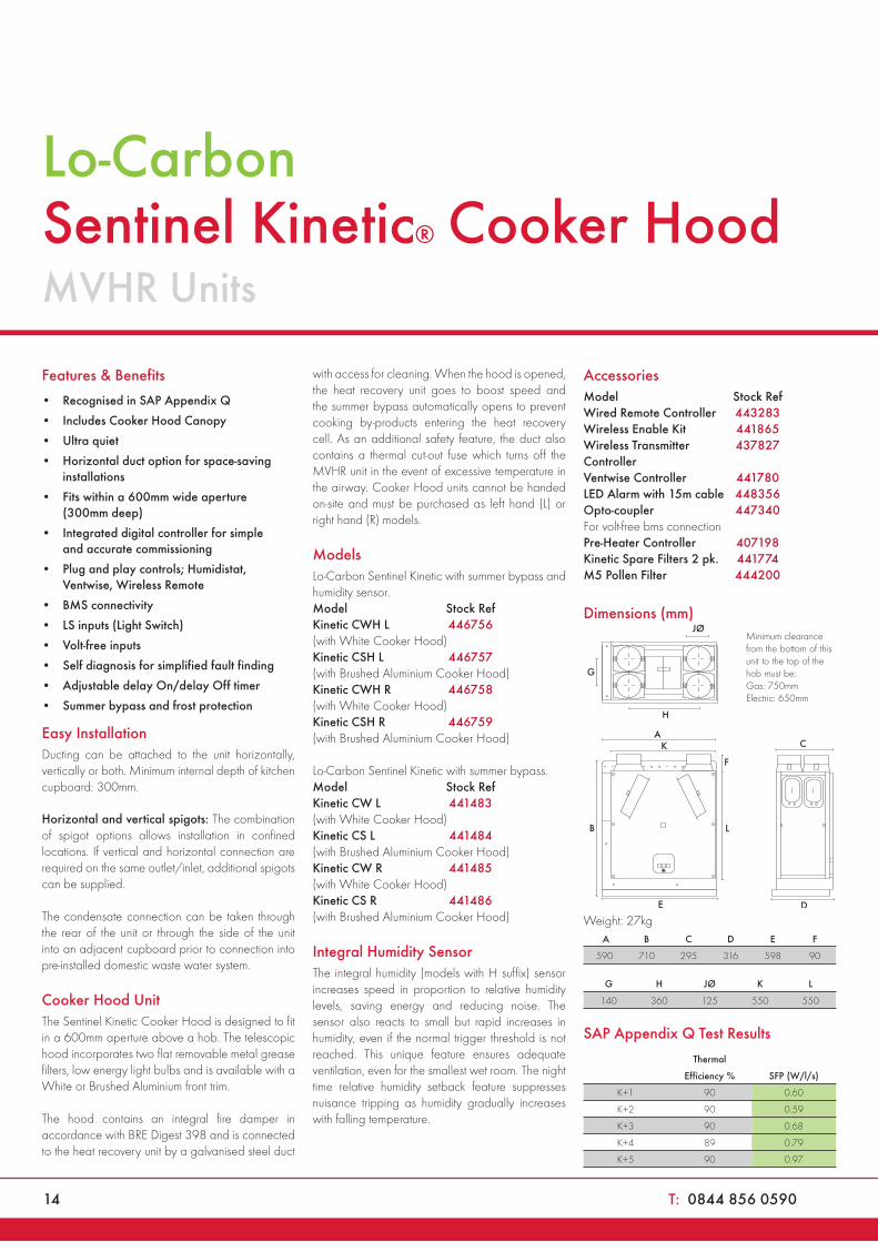
Cooker Hood UnitThe Sentinel Kinetic Cooker Hood is designed to fit in a 600mm aperture above a hob. The telescopic hood incorporates two flat removable metal grease filters, low energy light bulbs and is available with a White or Brushed Aluminium front trim.
The hood contains an integral fire damper in accordance with BRE Digest 398 and is connected to the heat recovery unit by a galvanised steel duct
with access for cleaning. When the hood is opened, the heat recovery unit goes to boost speed and the summer bypass automatically opens to prevent cooking by-products entering the heat recovery cell. As an additional safety feature, the duct also contains a thermal cut-out fuse which turns off the MVHR unit in the event of excessive temperature in the airway. Cooker Hood units cannot be handed on-site and must be purchased as left hand (L) or right hand (R) models.
Models CAS
Lo-Carbon Sentinel Kinetic with summer bypass and humidity sensor.Model Stock Ref £TradeKinetic CWH L 446756 1694.90(with White Cooker Hood)Kinetic CSH L 446757 1694.90(with Brushed Aluminium Cooker Hood)Kinetic CWH R 446758 1694.90(with White Cooker Hood)Kinetic CSH R 446759 1694.90(with Brushed Aluminium Cooker Hood)
Lo-Carbon Sentinel Kinetic with summer bypass.Model Stock Ref £Trade Kinetic CW L 441483 1655.41(with White Cooker Hood) Kinetic CS L 441484 1655.41(with Brushed Aluminium Cooker Hood) Kinetic CW R 441485 1655.41(with White Cooker Hood) Kinetic CS R 441486 1655.41(with Brushed Aluminium Cooker Hood)
Integral Humidity SensorThe integral humidity (models with H suffix) sensor increases speed in proportion to relative humidity levels, saving energy and reducing noise. The sensor also reacts to small but rapid increases in humidity, even if the normal trigger threshold is not reached. This unique feature ensures adequate ventilation, even for the smallest wet room. The night time relative humidity setback feature suppresses nuisance tripping as humidity gradually increases with falling temperature.
Accessories CAS
Model Stock Ref £TradeWired Remote Controller 443283 54.01Wireless Enable Kit 441865 81.02Wireless Transmitter 437827 50.11ControllerVentwise Controller 441780 182.28LED Alarm with 15m cable 448356 29.16Opto-coupler 447340 34.99For volt-free bms connectionPre-Heater Controller 407198 52.00Kinetic Spare Filters 2 pk. 441774 21.78M5 Pollen Filter 444200 21.78
Dimensions (mm)
A
F
B
C
DE
L
K
Minimum clearance from the bottom of this unit to the top of the hob must be: Gas: 750mm Electric: 650mm
G
JØ
H
Weight: 27kg A B C D E F
590 710 295 316 598 90
G H JØ K L
140 360 125 550 550
SAP Appendix Q Test Results
Thermal
Efficiency % SFP (W/l/s)
K+1 90 0.60
K+2 90 0.59
K+3 90 0.68
K+4 89 0.79
K+5 90 0.97
W: www.vent-axia.com/mvhr 15
MVHR Units
Example system curves -
vertical spigots
Example system curves -
horizontal spigots
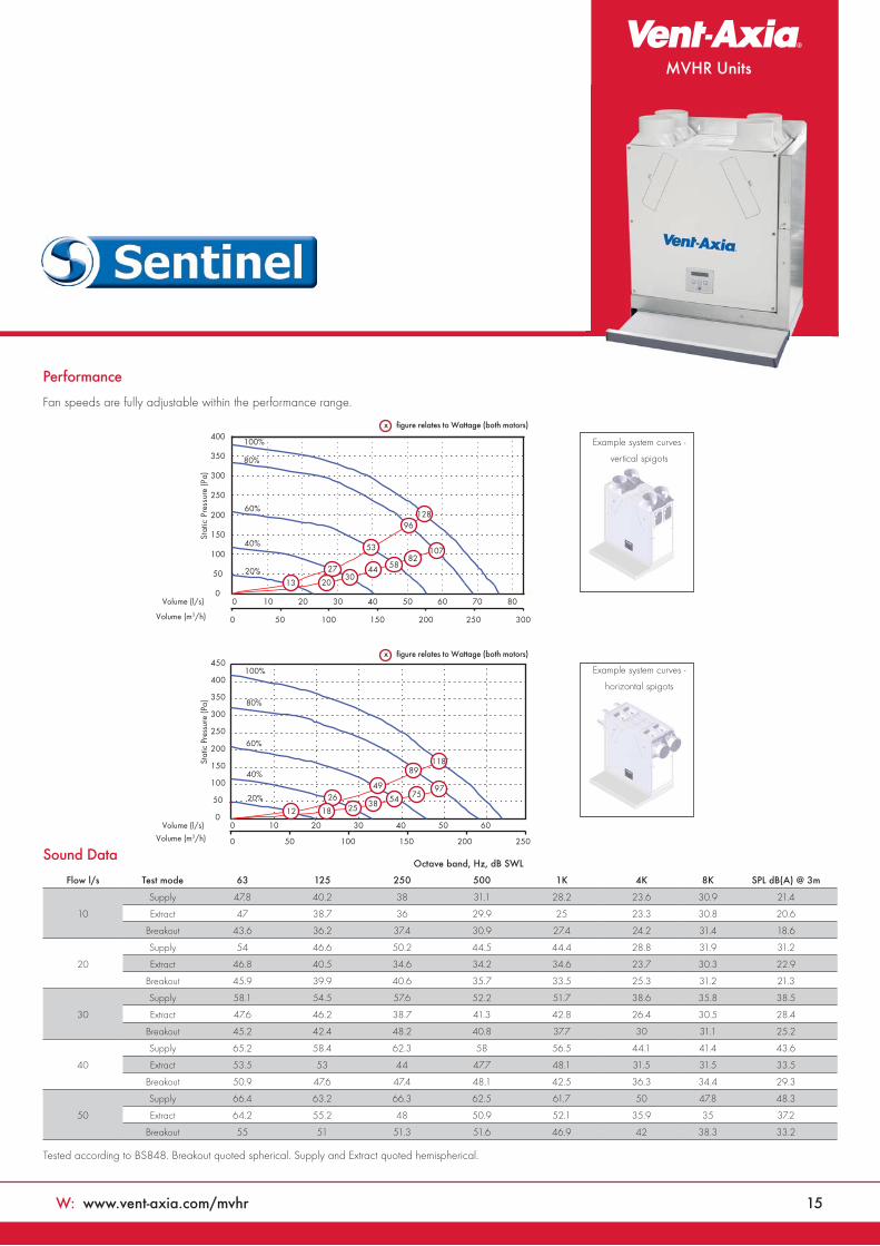
Performance
Fan speeds are fully adjustable within the performance range.
Sound Data
Tested according to BS848. Breakout quoted spherical. Supply and Extract quoted hemispherical.
0
50
100
150
200
250
300
350
400
450
Stat
ic P
ress
ure
(Pa)
20%
40%
60%
80%
100%
0
50
100
150
200
250
300
350
400
Stat
ic P
ress
ure
(Pa)
00 10 20 30 40 50 60 70 80
0 10 20 30 40 50 60
0 50 100 150 200 250
0 50 100 150 200 250 300
53
27
2030
44
128
107
20%
40%
60%
80%
100%
Volume (m3/h)
Volume (l/s)
Volume (m3/h)
Volume (l/s)
13
96
8258
x figure relates to Wattage (both motors)
x figure relates to Wattage (both motors)
12
4926
18 25 38
118
97
89
7554
Octave band, Hz, dB SWL
Flow l/s Test mode 63 125 250 500 1K 4K 8K SPL dB(A) @ 3m
10
Supply 47.8 40.2 38 31.1 28.2 23.6 30.9 21.4
Extract 47 38.7 36 29.9 25 23.3 30.8 20.6
Breakout 43.6 36.2 37.4 30.9 27.4 24.2 31.4 18.6
20
Supply 54 46.6 50.2 44.5 44.4 28.8 31.9 31.2
Extract 46.8 40.5 34.6 34.2 34.6 23.7 30.3 22.9
Breakout 45.9 39.9 40.6 35.7 33.5 25.3 31.2 21.3
30
Supply 58.1 54.5 57.6 52.2 51.7 38.6 35.8 38.5
Extract 47.6 46.2 38.7 41.3 42.8 26.4 30.5 28.4
Breakout 45.2 42.4 48.2 40.8 37.7 30 31.1 25.2
40
Supply 65.2 58.4 62.3 58 56.5 44.1 41.4 43.6
Extract 53.5 53 44 47.7 48.1 31.5 31.5 33.5
Breakout 50.9 47.6 47.4 48.1 42.5 36.3 34.4 29.3
50
Supply 66.4 63.2 66.3 62.5 61.7 50 47.8 48.3
Extract 64.2 55.2 48 50.9 52.1 35.9 35 37.2
Breakout 55 51 51.3 51.6 46.9 42 38.3 33.2
16 T: 0844 856 0590
Lo-Carbon Sentinel® Kinetic Cooker Hood
Consultants Specification
OperationThe supply and extract ventilation unit shall be a Sentinel Kinetic as manufactured by Vent-Axia and shall be sized as indicated on the drawings and shall be in accordance with the particular specification.
Supply air to the room shall be pre-heated by the extract air via the integrated composite plastic counterflow heat recovery cell. The Sentinel Kinetic shall automatically vary the ventilation rate via EC/DC motors, as it receives signals from one of the optional interconnected sensors. When a signal is received, the fans shall either vary their speed proportionally or on a trickle and boost principle.
The unit shall have the facility to commission the supply and extract fans individually via in-built minimum and maximum speed adjustment, or alternative wired remote control unit. The fans themselves shall have independent, infinitely variable speed control.
Unit specificationThe unit shall be manufactured with an ABS outer case construction, and incorporate a metal duct to the cooker hood, intumescent fire damper and thermal switch, in accordance with BRE Digest 398.
The unit shall have a high efficiency composite plastic counterflow heat exchanger, supply and extract filters, automatic summer bypass, integral minimum and maximum infinitely variable speed controls with facia mounted failure indication. The unit shall have low energy, high efficiency EC/DC fan/motor assemblies with sealed for life bearings. The impellers shall be high efficiency forward curved centrifugal type.
The unit shall have a heat exchanger cell with a thermal efficiency of up to 92% when tested to EN 308. This shall be protected by G3 grade synthetic filters on supply and extract. Complete with a condensate drip tray and drain connection.
The unit shall be constructed with a removable Core allowing full maintenance access. The removable Core shall provide access to the following:
Supply and extract filter Heat exchanger Access to the electrical connections
Access shall be provided for wiring termination and setup/commissioning. The backlit LCD user interface therein shall be removable for remote mounting if required.
Units shall be as manufactured by Vent-Axia Ltd.
Standard controlsAll Sentinel Kinetic units shall incorporate the following functions integrally mounted, pre-wired and factory fitted by the manufacturer:
Integral infinitely variable fan speed control on supply and extract
Integral min/max ventilation control/set point Integral BMS interfaces – control and status
indication Heating interlocks 0-10V proportional speed adjustment Volt free contacts 24V sensor supply Integral on/off or trickle boost function from
remote switch e.g. PIR occupancy detector The unit shall be controlled by the ‘Sentinel’
control devices (enablers and sensors) as detailed in the schedule or on the drawings
Fully automatic summer bypass Switched Live input with adjustable ‘Delay-On’
feature Fan failure or component failure indicated via
individual fault code display Running time counter Control panel PIN number lock Automatic frost protection effective to -20°C Tool free filter access The unit shall incorporate (‘H’ models) an
integral humidity sensor with the following features:
• Ambient Response; Raises the humidity trigger point as dwelling temperature reduces
• Rapid Response; Monitors the rate of change in humidity and triggers increased airflow even if the humidity trigger threshold is not reached
• Proportional Response; Incrementally increases the fan speed to reduce noise and reduce energy consumption
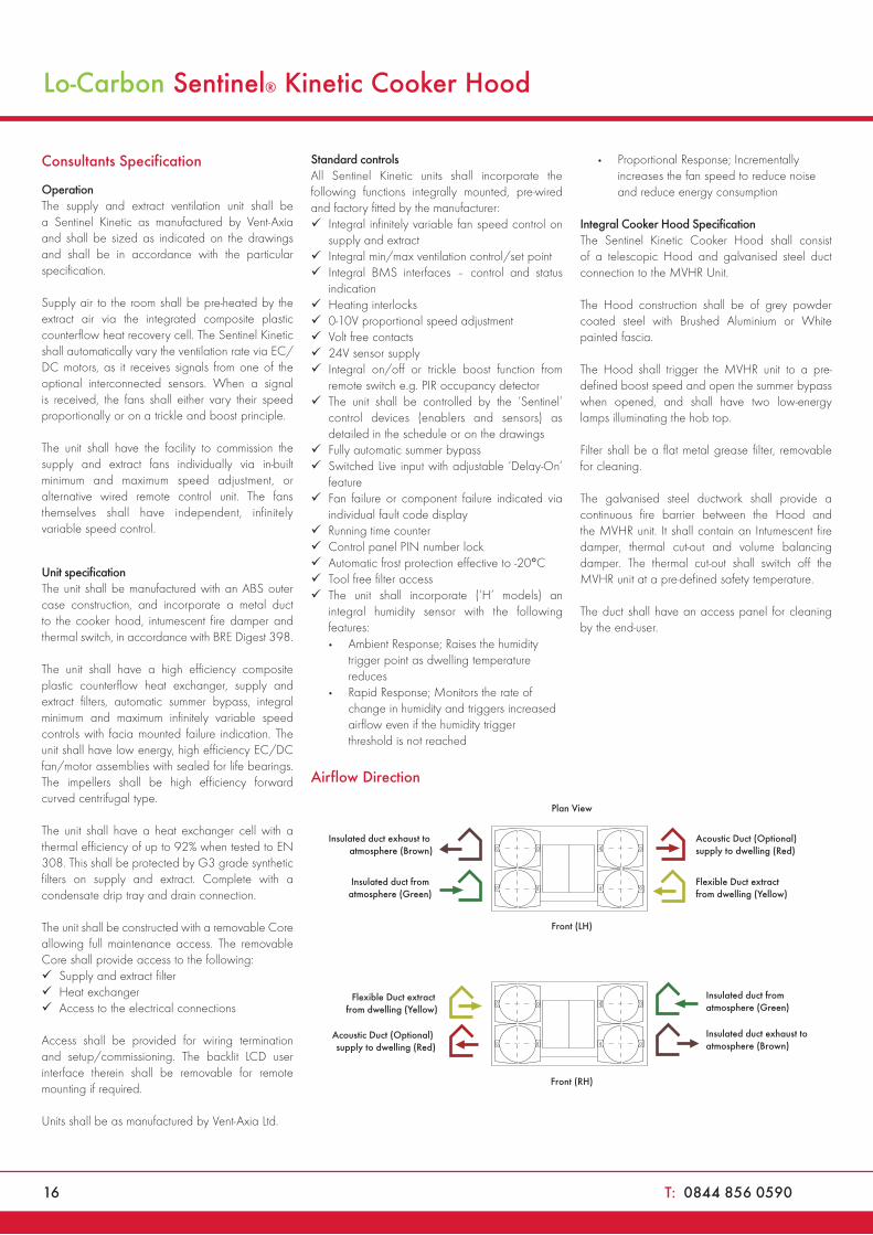
Integral Cooker Hood SpecificationThe Sentinel Kinetic Cooker Hood shall consist of a telescopic Hood and galvanised steel duct connection to the MVHR Unit.
The Hood construction shall be of grey powder coated steel with Brushed Aluminium or White painted fascia.
The Hood shall trigger the MVHR unit to a pre-defined boost speed and open the summer bypass when opened, and shall have two low-energy lamps illuminating the hob top.
Filter shall be a flat metal grease filter, removable for cleaning.
The galvanised steel ductwork shall provide a continuous fire barrier between the Hood and the MVHR unit. It shall contain an Intumescent fire damper, thermal cut-out and volume balancing damper. The thermal cut-out shall switch off the MVHR unit at a pre-defined safety temperature.
The duct shall have an access panel for cleaning by the end-user.
Airflow Direction
Flexible Duct extract from dwelling (Yellow)
Acoustic Duct (Optional) supply to dwelling (Red)
Insulated duct from atmosphere (Green)
Insulated duct exhaust to atmosphere (Brown)
Front (RH)
Flexible Duct extract from dwelling (Yellow)
Acoustic Duct (Optional) supply to dwelling (Red)
Insulated duct from atmosphere (Green)
Insulated duct exhaust to atmosphere (Brown)
Front (LH)
Plan View
MVHR Units
W: www.vent-axia.com/mvhr 17
MVHR Units
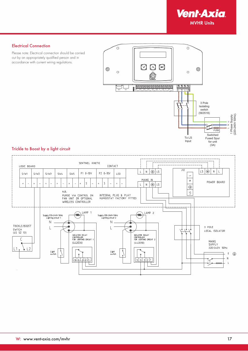
Trickle to Boost by a light circuit
Electrical Connection
Please note: Electrical connection should be carried out by an appropriately qualified person and in accordance with current wiring regulations.
18 T: 0844 856 0590
Lo-CarbonKinetic® EMVHR Unit
Features & Benefits• Compact size
• Lightweight for easy installation
• Easy access filters
• External condensate connection
• Compatible with a range of controls: PIR, Humidistat
• Horizontal duct option for space-saving installations
• Energy saving EC/DC motors
• Quiet operation
• Manufactured in the UK
• Switched live inputs (Light switch control)
A wholehouse heat recovery system with 91% energy efficiency. An easily accessible heat recovery cube protected by two removable EU3 filters. Two Lo-Carbon Energy Saving EC/DC fans ensure long life (typically over double the life of AC motors) and lowest possible energy use. Fully insulated construction with built-in condensation drain.
Lo-Carbon Kinetic E meets the latest requirements of the Building Regulations Approved Document F and L for wholehouse system ventilation.
The Lo-Carbon Kinetic E model has two adjustable speeds: normal and boost. On the front of the unit is the controller that can be used to preset the speeds to any required performance, up to 38l/s (135m3/hr) 100Pa. Offering ‘Close Control’ to prevent over ventilating. Acoustically lined - low noise levels from only 20dB(A) @3m.
Left or right hand installation
Units are supplied right handed with duct spigots to outside on the right hand side. These can be reversed on site by simply removing the control panel, rotating the unit 180 degrees and re-attaching the control panel.
Spigot Options
The combination of spigot options allows installation in confined locations. If vertical and horizontal connection is required on the same outlet/inlet, additional spigots can be supplied.
Filter Check
An LED on the control panel illuminates at six month intervals to remind users to check and clean the filters.
Frost Protection
The Kinetic E range benefits from an automatic frost protection system which manages the airflows to prevent the heat recovery cell freezing in very cold weather, while at the same time maintaining ventilation down to -20°C.
Control options
There are two LS (Switched Live) inputs allowing the unit to be connected to a number of sensors and controllers such as Ventwise, Timespan, Ambient Response Humidistat. One of the LS connections also benefits from a ‘Delay On’ feature which prevents the unit boosting unnecessarily.
Model CAS
Model Stock Ref £ TradeKinetic E 443303 1093.07
Accessories SP
Model Stock Ref £ Trade Kinetic Spare 442356 21.78Filters 2 PackOptional M5 444199 21.78Pollen Filter
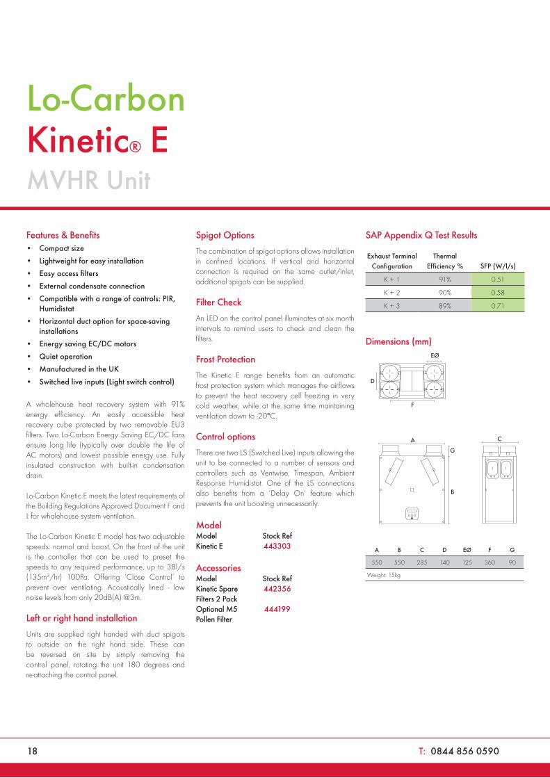
SAP Appendix Q Test Results
Exhaust Terminal Configuration
Thermal Efficiency % SFP (W/l/s)
K + 1 91% 0.51
K + 2 90% 0.58
K + 3 89% 0.71
Dimensions (mm)
G
C
D
B
EØ
F
A
A B C D EØ F G
550 550 285 140 125 360 90
Weight: 15kg
W: www.vent-axia.com/mvhr 19
MVHR Units
0
50
100Prrs
sure
Pa
Volume
K+1
K+2
K+3
Max
150
200
250
0 10 20 30 40 50 l/s
0 20 40 60 80 100 120 140 160 180 m3/h
11
11
12
12
14
13
13
14
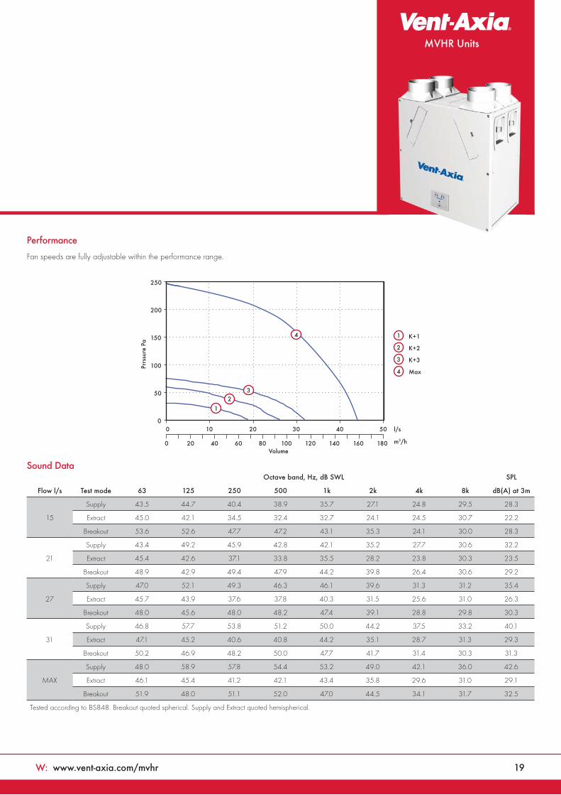
Performance
Fan speeds are fully adjustable within the performance range.
Sound Data
Flow l/s
Octave band, Hz, dB SWL SPL
Test mode 63 125 250 500 1k 2k 4k 8k dB(A) at 3m
15
Supply 43.5 44.7 40.4 38.9 35.7 27.1 24.8 29.5 28.3
Extract 45.0 42.1 34.5 32.4 32.7 24.1 24.5 30.7 22.2
Breakout 53.6 52.6 47.7 47.2 43.1 35.3 24.1 30.0 28.3
21
Supply 43.4 49.2 45.9 42.8 42.1 35.2 27.7 30.6 32.2
Extract 45.4 42.6 37.1 33.8 35.5 28.2 23.8 30.3 23.5
Breakout 48.9 42.9 49.4 47.9 44.2 39.8 26.4 30.6 29.2
27
Supply 47.0 52.1 49.3 46.3 46.1 39.6 31.3 31.2 35.4
Extract 45.7 43.9 37.6 37.8 40.3 31.5 25.6 31.0 26.3
Breakout 48.0 45.6 48.0 48.2 47.4 39.1 28.8 29.8 30.3
31
Supply 46.8 57.7 53.8 51.2 50.0 44.2 37.5 33.2 40.1
Extract 47.1 45.2 40.6 40.8 44.2 35.1 28.7 31.3 29.3
Breakout 50.2 46.9 48.2 50.0 47.7 41.7 31.4 30.3 31.3
MAX
Supply 48.0 58.9 57.8 54.4 53.2 49.0 42.1 36.0 42.6
Extract 46.1 45.4 41.2 42.1 43.4 35.8 29.6 31.0 29.1
Breakout 51.9 48.0 51.1 52.0 47.0 44.5 34.1 31.7 32.5
Tested according to BS848. Breakout quoted spherical. Supply and Extract quoted hemispherical.
20 T: 0844 856 0590
Lo-Carbon Kinetic® E
Consultants Specification
Operation The supply and extract ventilation unit shall be as Kinetic E as manufactured by Vent-Axia and shall be sized as indicated on the drawings and shall be in accordance with the particular specification. Supply air to the room shall be pre-heated by the extract air via the integrated composite plastic counterflow heat recovery cell. The Kinetic E shall automatically vary the ventilation rate via EC/DC motors, as it receives signals from one of the optional interconnected sensors. When a signal is received, the fans shall vary their speed on a trickle and boost principle. The unit shall have the facility to commission the supply and extract fans individually via in-built minimum and maximum speed adjustment. The fans themselves shall have independent, infinitely variable speed control.
Unit specificationThe unit shall be manufactured with an ABS outer case construction, and incorporate a reversible core to allow for left or right hand mounting. The unit shall have a high efficiency composite plastic counterflow heat exchanger, supply and extract filters, integral minimum and maximum infinitely variable speed controls with facia mounted failure indication.
The unit shall have low energy, high efficiency EC/DC fan/motor assemblies with sealed for life bearings. The impellers shall be high efficiency forward curved centrifugal type. The unit shall have a heat exchanger cell with a thermal efficiency of up to 91% when tested to EN 308. This shall be protected by G3 grade synthetic filters on supply and extract. Complete with a condensate drip tray and drain connection.
The unit shall be constructed with a removable Core allowing full maintenance access. The removable Core shall provide access to the following:
Supply and extract filter
Heat exchanger
Access to the electrical connections
Access shall be provided for wiring termination and setup/commissioning.
Standard controlsAll Kinetic E units shall incorporate the following functions integrally mounted, pre-wired and factory fitted by the manufacturer:
Integral infinitely variable fan speed control on supply and extract
Integral min/max ventilation control/set point
Integral on/off or trickle boost function from
remote switch, e.g. PIR occupancy detector
Switched Live input with adjustable
‘Delay-On’ feature
Tool free filter access
Frost protection down to -20°C
LED 'filter check' indicator
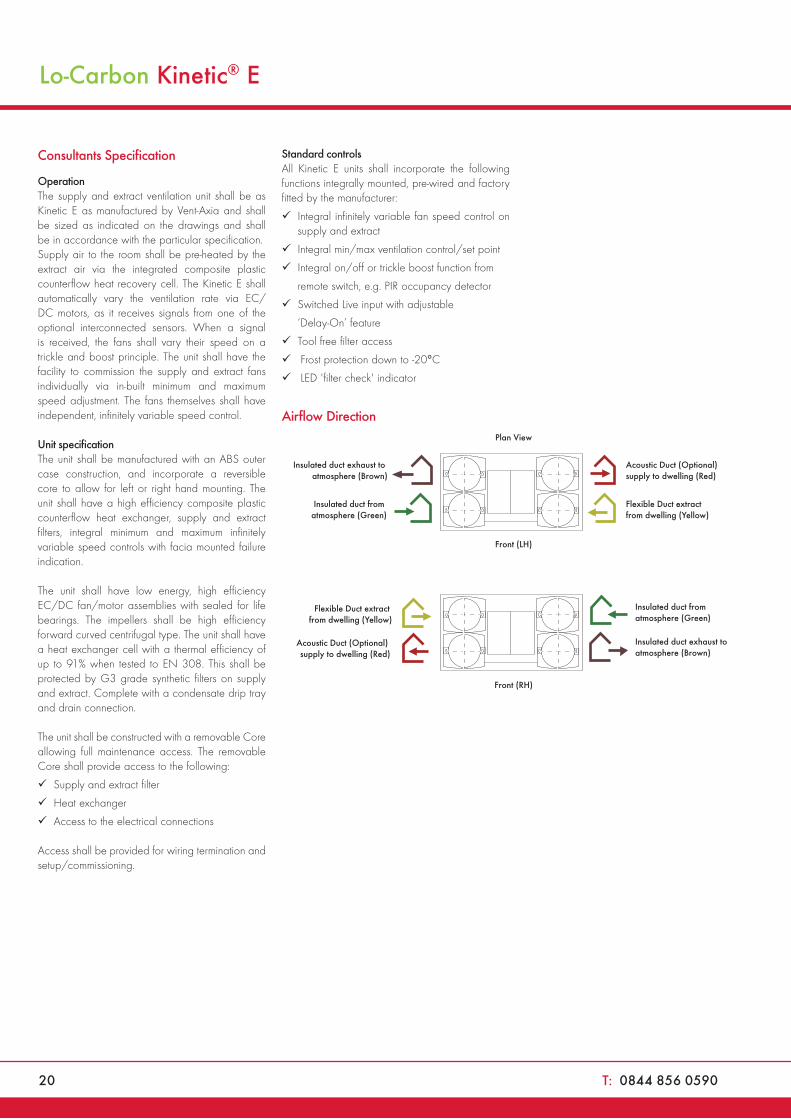
Airflow Direction
Flexible Duct extract from dwelling (Yellow)
Acoustic Duct (Optional) supply to dwelling (Red)
Insulated duct from atmosphere (Green)
Insulated duct exhaust to atmosphere (Brown)
Front (RH)
Flexible Duct extract from dwelling (Yellow)
Acoustic Duct (Optional) supply to dwelling (Red)
Insulated duct from atmosphere (Green)
Insulated duct exhaust to atmosphere (Brown)
Front (LH)
Plan View
MVHR Units
W: www.vent-axia.com/mvhr 21
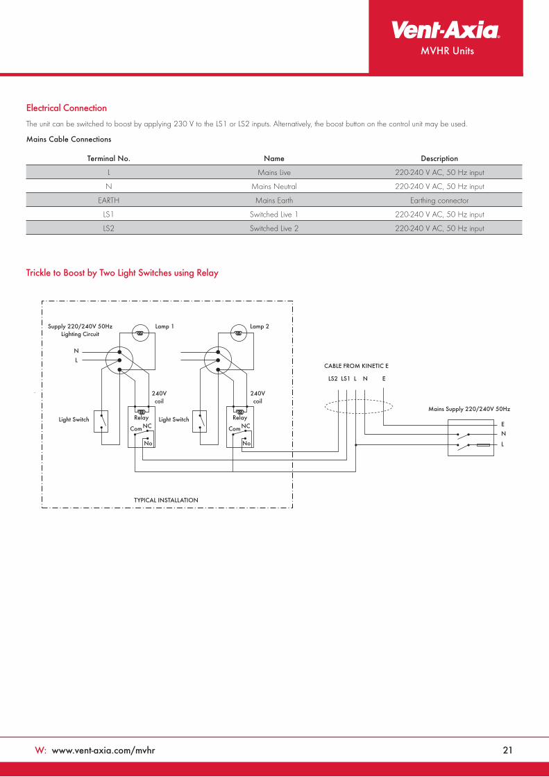
Electrical Connection
The unit can be switched to boost by applying 230 V to the LS1 or LS2 inputs. Alternatively, the boost button on the control unit may be used.
Mains Cable Connections
Terminal No. Name Description
L Mains Live 220-240 V AC, 50 Hz input
N Mains Neutral 220-240 V AC, 50 Hz input
EARTH Mains Earth Earthing connector
LS1 Switched Live 1 220-240 V AC, 50 Hz input
LS2 Switched Live 2 220-240 V AC, 50 Hz input
Trickle to Boost by Two Light Switches using Relay
CABLE FROM KINETIC E
LS2 LS1 L N E
Mains Supply 220/240V 50Hz
Supply 220/240V 50HzLighting Circuit
Light Switch Light Switch
N
L
E
N
L
TYPICAL INSTALLATION
Lamp 1
240Vcoil
RelayNCCom
No
240Vcoil
RelayNCCom
No
Lamp 2
22 T: 0844 856 0590
Lo-CarbonKinetic® Plus EMVHR Unit
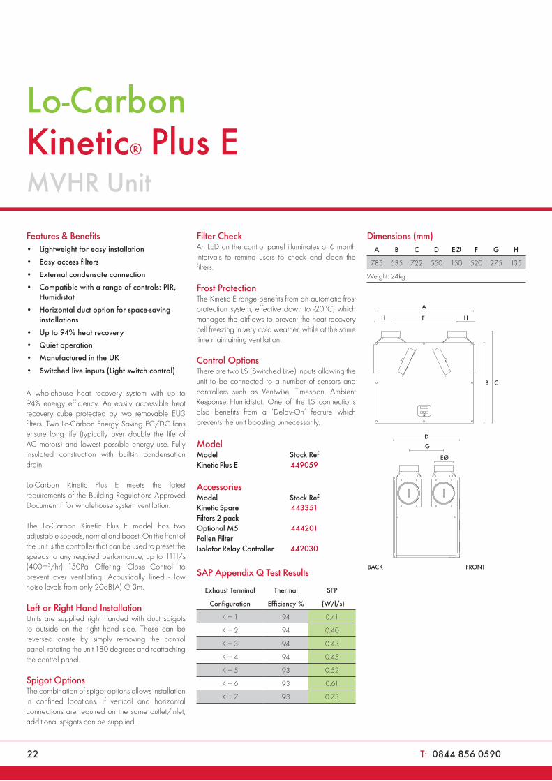
Features & Benefits• Lightweight for easy installation
• Easy access filters
• External condensate connection
• Compatible with a range of controls: PIR, Humidistat
• Horizontal duct option for space-saving installations
• Up to 94% heat recovery
• Quiet operation
• Manufactured in the UK
• Switched live inputs (Light switch control)
A wholehouse heat recovery system with up to 94% energy efficiency. An easily accessible heat recovery cube protected by two removable EU3 filters. Two Lo-Carbon Energy Saving EC/DC fans ensure long life (typically over double the life of AC motors) and lowest possible energy use. Fully insulated construction with built-in condensation drain.
Lo-Carbon Kinetic Plus E meets the latest requirements of the Building Regulations Approved Document F for wholehouse system ventilation.
The Lo-Carbon Kinetic Plus E model has two adjustable speeds, normal and boost. On the front of the unit is the controller that can be used to preset the speeds to any required performance, up to 111l/s (400m3/hr) 150Pa. Offering ‘Close Control’ to prevent over ventilating. Acoustically lined - low noise levels from only 20dB(A) @ 3m.
Left or Right Hand InstallationUnits are supplied right handed with duct spigots to outside on the right hand side. These can be reversed onsite by simply removing the control panel, rotating the unit 180 degrees and reattaching the control panel.
Spigot OptionsThe combination of spigot options allows installation in confined locations. If vertical and horizontal connections are required on the same outlet/inlet, additional spigots can be supplied.
Filter CheckAn LED on the control panel illuminates at 6 month intervals to remind users to check and clean the filters.
Frost ProtectionThe Kinetic E range benefits from an automatic frost protection system, effective down to -20°C, which manages the airflows to prevent the heat recovery cell freezing in very cold weather, while at the same time maintaining ventilation.
Control OptionsThere are two LS (Switched Live) inputs allowing the unit to be connected to a number of sensors and controllers such as Ventwise, Timespan, Ambient Response Humidistat. One of the LS connections also benefits from a ‘Delay-On’ feature which prevents the unit boosting unnecessarily.
Model CAS
Model Stock Ref £TradeKinetic Plus E 449059 1586.55
Accessories SP
Model Stock Ref £TradeKinetic Spare 443351 34.62Filters 2 packOptional M5 444201 32.98Pollen Filter Isolator Relay Controller 442030 60.76
SAP Appendix Q Test Results
Exhaust Terminal Thermal SFP
Configuration Efficiency % (W/l/s)
K + 1 94 0.41
K + 2 94 0.40
K + 3 94 0.43
K + 4 94 0.45
K + 5 93 0.52
K + 6 93 0.61
K + 7 93 0.73
Dimensions (mm)A B C D EØ F G H
785 635 722 550 150 520 275 135
Weight: 24kg
BACK FRONT

W: www.vent-axia.com/mvhr 23
MVHR Units
0
100
200
300
400
500
600
0
0 50 100 150 200 250 300 350 400 450 500 550
20 40 60 80 100 120 140 160
Stat
ic P
ress
ure
(Pa)
Volume
l/s
m3/h
20%40%
80%
100%
60%
Performance
Fan speeds are fully adjustable within the performance range.
Sound Data
Tested according to BS848. Breakout quoted spherical. Supply and Extract quoted hemispherical.
Octave band, Hz, dB SWL SPL dB(A)
Flow l/s Unit setting Test mode 63 125 250 500 1k 2k 4k 8k at 3m
50 20%
Supply 46.5 54.3 46.4 44.8 36.2 28.5 24.5 31.2 28.5
Extract 46 52.2 42.3 38.7 27.6 24.2 24 31.7 25
Breakout 48.5 42.6 43.3 38.9 35.8 29.3 23.8 30.7 22.8
78 40%
Supply 50.3 59.1 54.5 56.5 47 39.9 26.3 31.7 38
Extract 46.8 51.6 47.8 44.4 32.7 27.4 24.4 31.7 28
Breakout 48.4 51.2 53.4 46 41 34.6 25 30.3 28.5
104 60%
Supply 52.4 57.2 60.4 60.9 55.8 50.3 33.1 33.9 43.6
Extract 50 49.8 56.8 52.4 40.2 35.9 33.4 39.8 35.2
Breakout 55 49.6 59.7 54.5 46.9 39.9 33.6 39.2 34.9
127 80%
Supply 54.9 60.7 67.4 66.6 61.8 56 39.6 37.7 49.5
Extract 50.4 52 61.2 56.6 45.1 39.6 34.2 40.2 39.1
Breakout 53.5 53.4 60.8 59.1 53 45.3 36 40.1 38.7
137 100%
Supply 54.7 61.7 70.5 69.9 62.7 57.5 42.1 38.3 52
Extract 54.4 55.1 65.8 57.5 46.9 40.6 33.7 40 41.8
Breakout 56.6 54.6 60.5 60.7 54.7 45.9 36.5 39.6 40
24 T: 0844 856 0590
Consultants Specification
OperationThe supply and extract ventilation unit shall be as Kinetic Plus E as manufactured by Vent-Axia and shall be sized as indicated on the drawings and shall be in accordance with the particular specification.
Supply air to the room shall be pre-heated by the extract air via the integrated composite plastic counterflow heat recovery cell. The Kinetic Plus E shall automatically vary the ventilation rate via EC/DC motors, as it receives signals from one of the optional interconnected sensors. When a signal is received, the fans shall vary their speed on a trickle and boost principle. The unit shall have the facility to commission the supply and extract fans individually via in-built minimum and maximum speed adjustment. The fans themselves shall have independent, infinitely variable speed control.
Unit specificationThe unit shall be manufactured with an ABS outer case construction, and incorporate a reversible core to allow for left or right hand mounting. The unit shall have a high efficiency composite plastic counterflow heat exchanger, supply and extract filters, integral minimum and maximum infinitely variable speed controls with facia mounted failure indication.
The unit shall have low energy, high efficiency EC/DC fan/motor assemblies with sealed for life bearings. The impellers shall be high efficiency backward curved centrifugal type. The unit shall have a heat exchanger cell with a thermal efficiency of up to 94% when tested to EN 308. This shall be protected by G3 grade synthetic filters on supply and extract. Complete with a condensate drip tray and drain connection.
The unit shall be constructed with a removable Core allowing full maintenance access. The removableCore shall provide access to the following:
Supply and extract filter
Heat exchanger
Access to the electrical connections
Access shall be provided for wiring termination and setup/commissioning.
Standard controlsAll Kinetic Plus E units shall incorporate the following functions integrally mounted, pre-wired and factory fitted by the manufacturer:
Integral infinitely variable fan speed control on supply and extract
Integral min/max ventilation control/set point
Integral on/off or trickle boost function from remote switch, e.g. PIR occupancy detector
Switched Live input with adjustable ‘delay-on’ feature
Tool free filter access
Frost protection down to -20°C
LED 'filter check' indicator
Lo-Carbon Kinetic Plus E
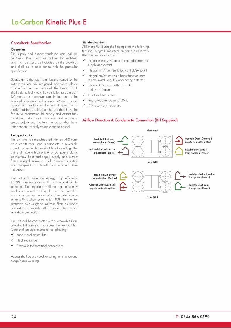
Airflow Direction & Condensate Connection (RH Supplied)
Flexible Duct extract from dwelling (Yellow)
Acoustic Duct (Optional) supply to dwelling (Red)
Insulated duct from atmosphere (Green)
Insulated duct exhaust to atmosphere (Brown)
Front (RH)
Flexible Duct extract from dwelling (Yellow)
Acoustic Duct (Optional) supply to dwelling (Red)
Insulated duct from atmosphere (Green)
Insulated duct exhaust to atmosphere (Brown)
Front (LH)
Plan View

MVHR Units
W: www.vent-axia.com/mvhr 25
Electrical Connection
The unit can be switched to boost by applying 230 V to the LS1 or LS2 inputs. Alternatively, the boost button on the control unit may be used.
Mains Cable Connections
Terminal No. Name Description
L Mains Live 220-240 V AC, 50 Hz input
N Mains Neutral 220-240 V AC, 50 Hz input
EARTH Mains Earth Earthing connector
LS1 Switched Live 1 220-240 V AC, 50 Hz input
LS2 Switched Live 2 220-240 V AC, 50 Hz input
CABLE FROM KINETIC E
LS2 LS1 L N E
Mains Supply 220/240V 50Hz
Supply 220/240V 50HzLighting Circuit
Light Switch Light Switch
N
L
E
N
L
TYPICAL INSTALLATION
Lamp 1
240Vcoil
RelayNCCom
No
240Vcoil
RelayNCCom
No
Lamp 2
26 T: 0844 856 0590
Lo-CarbonSentinel Kinetic® HorizontalMVHR Units
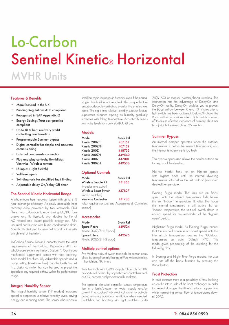
Features & Benefits
• Manufactured in the UK
• Building Regulations ADF compliant
• Recognised in SAP Appendix Q
• Energy Savings Trust best practice compliant
• Up to 81% heat recovery whilst controlling condensation
• Programmable Summer bypass
• Digital controller for simple and accurate commissioning
• External condensate connection
• Plug and play controls; Humidistat, Ventwise, Wireless remote
• LS inputs (Light Switch)
• Volt-free inputs
• Self diagnosis for simplified fault finding
• Adjustable delay On/delay Off timer
The Sentinel Kinetic Horizontal RangeA wholehouse heat recovery system with up to 81% heat exchange efficiency. An easily accessible heat recovery cube protected by two removable EU3 filters. Two Lo-Carbon Energy Saving EC/DC fans ensure long life (typically over double the life of AC motors) and lowest possible energy use. Fully insulated construction with built-in condensation drain. Specifically designed for new build constructions with a high level of insulation.
Lo-Carbon Sentinel Kinetic Horizontal meets the latest requirements of the Building Regulations ADF for wholehouse system ventilation: System 4. Continuous mechanical supply and extract with heat recovery. Each model has three fully adjustable speeds and a purge setting (maximum flow). Supplied with the unit is a digital controller that can be used to pre-set the speeds to any required airflow within the performance range.
Integral Humidity SensorThe integral humidity sensor (‘H’ models) increases speed in proportion to relative humidity levels, saving energy and reducing noise. The sensor also reacts to
small but rapid increases in humidity, even if the normal trigger threshold is not reached. This unique feature ensures adequate ventilation, even for the smallest wet room. The night time relative humidity setback feature suppresses nuisance tripping as humidity gradually increases with falling temperature. Acoustically lined - low noise levels from only 20dB(A) @ 3m.
Models CAS
Model Stock Ref £TradeKinetic 200ZP 407161 1010.00Kinetic 200ZPH 407162 1090.00Kinetic 200Z 448733 1343.51Kinetic 200ZH 449540 1424.52Kinetic 300Z 447801 1592.14Kinetic 300ZH 449536 1673.16
Optional Controls CAS
Model Stock Ref £TradeWireless Enable Kit 441865 81.02(includes one switch)Wireless Boost Switch 437827 50.11(max 3 switches) Ventwise Controller 441780 182.28(also requires sensors: see Accessories & Controllers section)
AccessoriesModel Stock Ref £TradeSpare Filters 449524 17.71Kinetic 200Z/ZH (2 pack)Spare Filters 449575 19.90Kinetic 300Z/ZH (2 pack)
Multiple control options:Five Volt-free pairs of switch terminals for sensor inputs allow boosting from a full range of Vent-Axia controllers – humidistats, PIR, timers.
Two terminals with 0-24V outputs allow 0V to 10V proportional control by sophisticated controllers such as CO2 sensors and proportional humidistats.
The optional Ventwise controller senses temperature rise in a bath/shower hot water supply and/or current in a cooker/hob electrical circuit to activate boost, ensuring additional ventilation when needed. Switch-live for boosting via light switches (220-
240V AC) or manual Normal/Boost switches. This connection has the advantage of Delay-On and Delay-Off facility. Delay-On enables you to prevent the Boost airflow between 0 and 10 minutes after a light switch has been activated. Delay-Off allows the Boost airflow to continue after a light switch is turned off to ensure effective clearance of humidity. This timer is adjustable between 0 and 25 minutes.
Summer Bypass An internal damper operates when the external temperature is below the internal temperature, and the internal temperature is too high.
The bypass opens and allows the cooler outside air to help cool the dwelling.
Normal mode: Fans run on Normal speed with bypass open until the internal dwelling temperature falls below the set 'Indoor' (maximum desired) temperature.
Evening Purge mode: The fans run on Boost speed until the internal temperature falls below the set 'Indoor' temperature. If, after five hours the internal temperature is still above the set 'Indoor' temperature, the unit will switch down to normal speed for the remainder of the 'bypass open' period.
Night-time Purge mode: As Evening Purge, except that the unit will continue on Boost speed until the internal air temperature reaches the 'Outdoor' temperature set point (Default 14°C). This mode gives pre-cooling of the dwelling for the following day.
In Evening and Night Time Purge modes, the user can turn off the boost function by pressing the Boost button.
Frost ProtectionIn cold climates there is a possibility of frost building up on the intake side of the heat exchanger. In order to prevent damage, the Kinetic reduces supply flow while maintaining extract flow at temperatures down to -20°C.
W: www.vent-axia.com/mvhr 27
MVHR Units
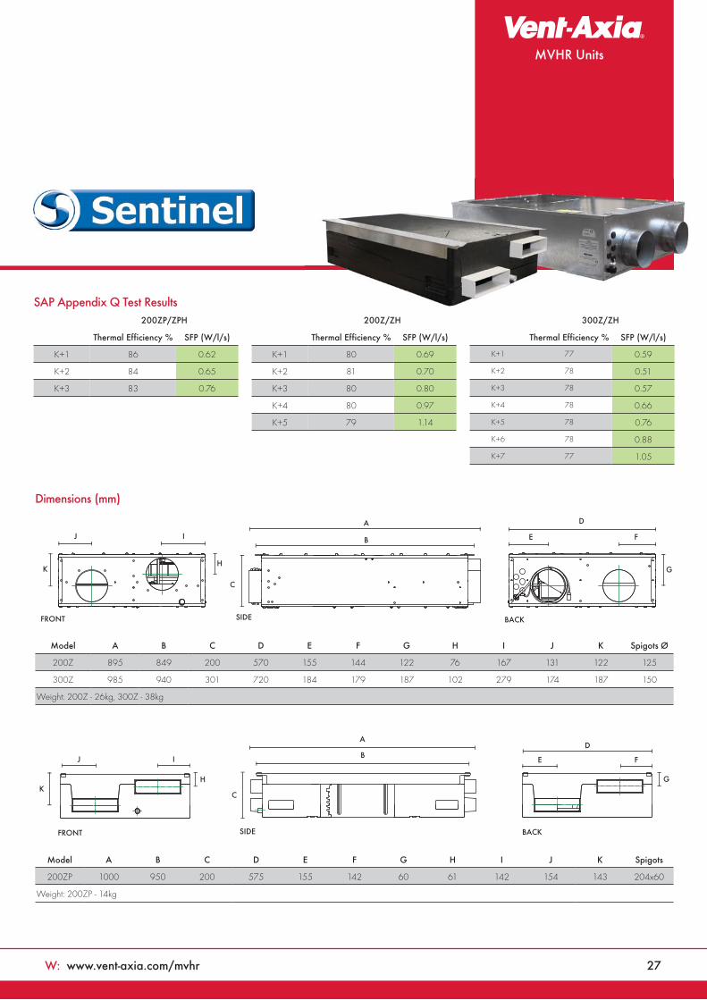
Model A B C D E F G H I J K Spigots Ø
200Z 895 849 200 570 155 144 122 76 167 131 122 125
300Z 985 940 301 720 184 179 187 102 279 174 187 150
Weight: 200Z - 26kg, 300Z - 38kg
Model A B C D E F G H I J K Spigots
200ZP 1000 950 200 575 155 142 60 61 142 154 143 204x60
Weight: 200ZP - 14kg
A
B
C
SIDEFRONT BACK
D
E F
GH
K
IJ
A
B
CK
H
SIDE
D
G
IJ E F
FRONT BACK
Dimensions (mm)
SAP Appendix Q Test Results200ZP/ZPH
Thermal Efficiency % SFP (W/l/s)
K+1 86 0.62
K+2 84 0.65
K+3 83 0.76
200Z/ZH
Thermal Efficiency % SFP (W/l/s)
K+1 80 0.69
K+2 81 0.70
K+3 80 0.80
K+4 80 0.97
K+5 79 1.14
300Z/ZH
Thermal Efficiency % SFP (W/l/s)
K+1 77 0.59
K+2 78 0.51
K+3 78 0.57
K+4 78 0.66
K+5 78 0.76
K+6 78 0.88
K+7 77 1.05
28 T: 0844 856 0590
Lo-Carbon Sentinel® Kinetic Horizontal
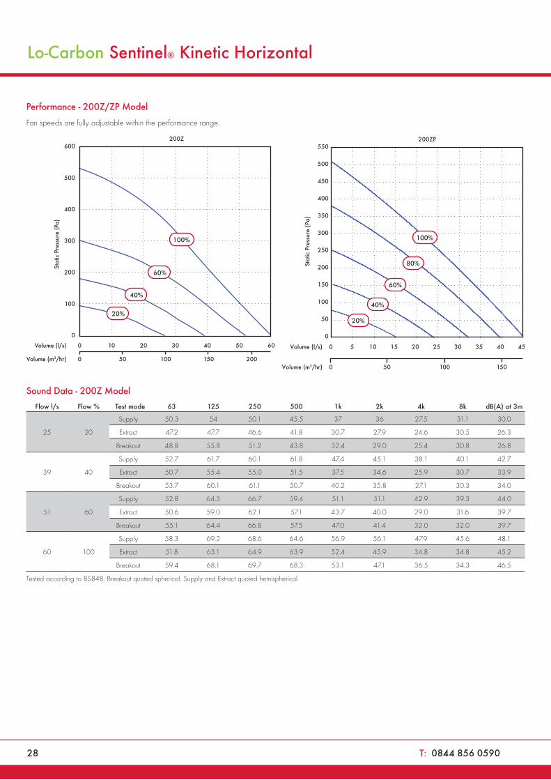
Performance - 200Z/ZP Model
Fan speeds are fully adjustable within the performance range.
600
500
400
300
200
100
0
Stat
ic P
ress
ure
(Pa)
200Z
60%
40%
20%
Volume (l/s) 0 10 20 30 40 50 60
Volume (m3/hr) 0 50 100 150 200
100%
0
50
100
150
200
250
300
350
400
450
550
500
0 5 10 15 20 25 30 35 40 45
Stat
ic P
ress
ure
(Pa)
Volume (l/s)
Volume (m3/hr) 0 50 100 150
100%
80%
60%
40%
20%
200ZP
Sound Data - 200Z Model
Flow l/s Flow % Test mode 63 125 250 500 1k 2k 4k 8k dB(A) at 3m
25 20
Supply 50.3 54 50.1 45.5 37 36 27.5 31.1 30.0
Extract 47.2 47.7 46.6 41.8 30.7 27.9 24.6 30.5 26.3
Breakout 48.8 55.8 51.2 43.8 32.4 29.0 25.4 30.8 26.8
39 40
Supply 52.7 61.7 60.1 61.8 47.4 45.1 38.1 40.1 42.7
Extract 50.7 55.4 55.0 51.5 37.5 34.6 25.9 30.7 33.9
Breakout 53.7 60.1 61.1 50.7 40.2 35.8 27.1 30.3 34.0
51 60
Supply 52.8 64.5 66.7 59.4 51.1 51.1 42.9 39.3 44.0
Extract 50.6 59.0 62.1 57.1 43.7 40.0 29.0 31.6 39.7
Breakout 55.1 64.4 66.8 57.5 47.0 41.4 32.0 32.0 39.7
60 100
Supply 58.3 69.2 68.6 64.6 56.9 56.1 47.9 45.6 48.1
Extract 51.8 63.1 64.9 63.9 52.4 45.9 34.8 34.8 45.2
Breakout 59.4 68.1 69.7 68.3 53.1 47.1 36.5 34.3 46.5
Tested according to BS848. Breakout quoted spherical. Supply and Extract quoted hemispherical.
MVHR Units
W: www.vent-axia.com/mvhr 29
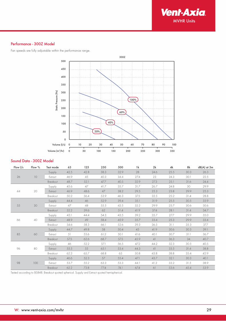
Sound Data - 300Z Model
0
150
100
50
250
200
450
400
350
300
500
Stat
ic P
ress
ure
(Pa)
0 10 20 30 40 50 60 70 80 90 100
0 50 100 150 200 250 300 350Volume (m3/hr)
Volume (l/s)
300Z
20%
40%
60%
100%
Flow l/s Flow % Test mode 63 125 250 500 1k 2k 4k 8k dB(A) at 3m
26 10
Supply 42.5 42.8 38.3 32.9 28 24.6 25.5 30.3 26.3
Extract 46.9 45 40.3 34.4 27.4 23 24.3 30.1 22.5
Breakout 48.7 52.1 47.7 40.5 32.9 27.3 25.1 31.6 24.4
44 20
Supply 45.6 47 41.7 35.7 31.7 26.7 24.8 30 29.9
Extract 46.9 48.6 47 38.2 29.5 25.3 23.8 29.9 25.3
Breakout 50.2 56.4 53.9 46.3 37.5 32.5 25.2 31.4 28.8
55 30
Supply 44.4 46 52.9 39.4 35.1 31.9 25.5 30.5 33.9
Extract 47 48 55.5 42.5 32.2 29.9 25.7 30.6 30.6
Breakout 52.2 59.6 62 51.4 41.9 37.4 28.1 31.4 34.7
66 40
Supply 43.1 44.4 54.3 43.5 39.2 35.7 27.7 29.9 35.0
Extract 48.9 49 58.4 45.9 35.7 33.4 25.3 29.9 33.4
Breakout 54.6 58.3 66.1 52.6 39.3 36.5 31.1 35.3 37.7
85 60
Supply 44.7 49.8 58 50.4 45 41.9 30.6 30.3 39.1
Extract 51 53.6 61.2 50.1 41.6 40.1 30.7 31.1 36.7
Breakout 57.5 62.6 68.7 57.5 45.9 41 36.3 34 40.7
96 80
Supply 46 52.2 57.1 56.5 47.2 44.2 32.3 30.5 40.5
Extract 55.5 55 63.1 53.4 44.3 41 33.5 31.4 38.8
Breakout 62.2 65.7 68.8 63 50.8 43.8 38.8 35.4 42.9
98 100
Supply 46.6 52.3 57 55.4 47.1 43.7 32.1 30.3 40.1
Extract 53.7 55.2 63.3 53.3 44.1 41.2 33.2 31.5 38.9
Breakout 62.2 73.8 77.4 74.1 67.4 61 53.6 45.4 53.9
Tested according to BS848. Breakout quoted spherical. Supply and Extract quoted hemispherical.
Performance - 300Z Model
Fan speeds are fully adjustable within the performance range.
30 T: 0844 856 0590
Lo-Carbon Sentinel® Kinetic Horizontal
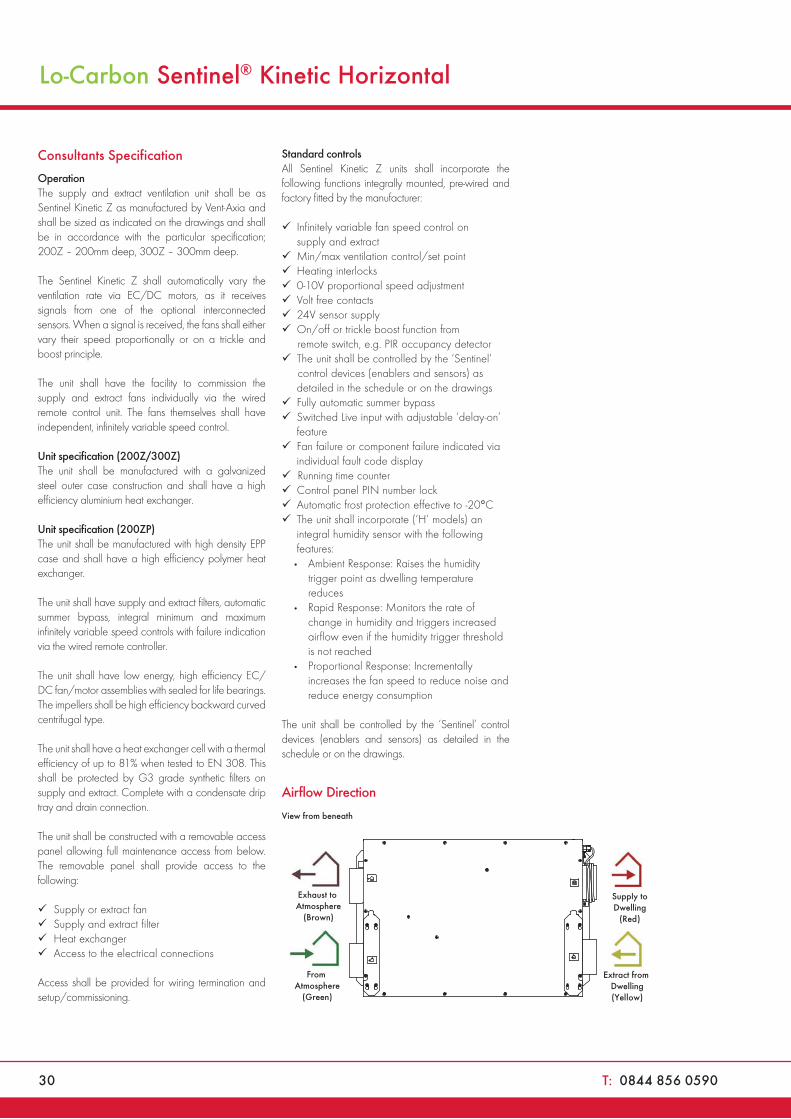
Consultants Specification
OperationThe supply and extract ventilation unit shall be as Sentinel Kinetic Z as manufactured by Vent-Axia and shall be sized as indicated on the drawings and shall be in accordance with the particular specification; 200Z – 200mm deep, 300Z – 300mm deep.
The Sentinel Kinetic Z shall automatically vary the ventilation rate via EC/DC motors, as it receives signals from one of the optional interconnected sensors. When a signal is received, the fans shall either vary their speed proportionally or on a trickle and boost principle.
The unit shall have the facility to commission the supply and extract fans individually via the wired remote control unit. The fans themselves shall have independent, infinitely variable speed control.
Unit specification (200Z/300Z)The unit shall be manufactured with a galvanized steel outer case construction and shall have a high efficiency aluminium heat exchanger.
Unit specification (200ZP)The unit shall be manufactured with high density EPP case and shall have a high efficiency polymer heat exchanger.
The unit shall have supply and extract filters, automatic summer bypass, integral minimum and maximum infinitely variable speed controls with failure indication via the wired remote controller.
The unit shall have low energy, high efficiency EC/DC fan/motor assemblies with sealed for life bearings. The impellers shall be high efficiency backward curved centrifugal type.
The unit shall have a heat exchanger cell with a thermal efficiency of up to 81% when tested to EN 308. This shall be protected by G3 grade synthetic filters on supply and extract. Complete with a condensate drip tray and drain connection.
The unit shall be constructed with a removable access panel allowing full maintenance access from below. The removable panel shall provide access to the following:
Supply or extract fan Supply and extract filter Heat exchanger Access to the electrical connections
Access shall be provided for wiring termination and setup/commissioning.
Standard controlsAll Sentinel Kinetic Z units shall incorporate the following functions integrally mounted, pre-wired and factory fitted by the manufacturer:
Infinitely variable fan speed control on supply and extract
Min/max ventilation control/set point Heating interlocks 0-10V proportional speed adjustment Volt free contacts 24V sensor supply On/off or trickle boost function from remote switch, e.g. PIR occupancy detector
The unit shall be controlled by the ‘Sentinel’ control devices (enablers and sensors) as detailed in the schedule or on the drawings
Fully automatic summer bypass Switched Live input with adjustable ‘delay-on’ feature
Fan failure or component failure indicated via individual fault code display
Running time counter Control panel PIN number lock Automatic frost protection effective to -20°C The unit shall incorporate (‘H’ models) an integral humidity sensor with the following features:
• Ambient Response: Raises the humidity trigger point as dwelling temperature reduces
• Rapid Response: Monitors the rate of change in humidity and triggers increased airflow even if the humidity trigger threshold is not reached
• Proportional Response: Incrementally increases the fan speed to reduce noise and reduce energy consumption
The unit shall be controlled by the ‘Sentinel’ control devices (enablers and sensors) as detailed in the schedule or on the drawings.
Airflow Direction
Extract from Dwelling(Yellow)
From Atmosphere
(Green)
Exhaust to Atmosphere
(Brown)
View from beneath
Supply toDwelling
(Red)
MVHR Units
W: www.vent-axia.com/mvhr 31
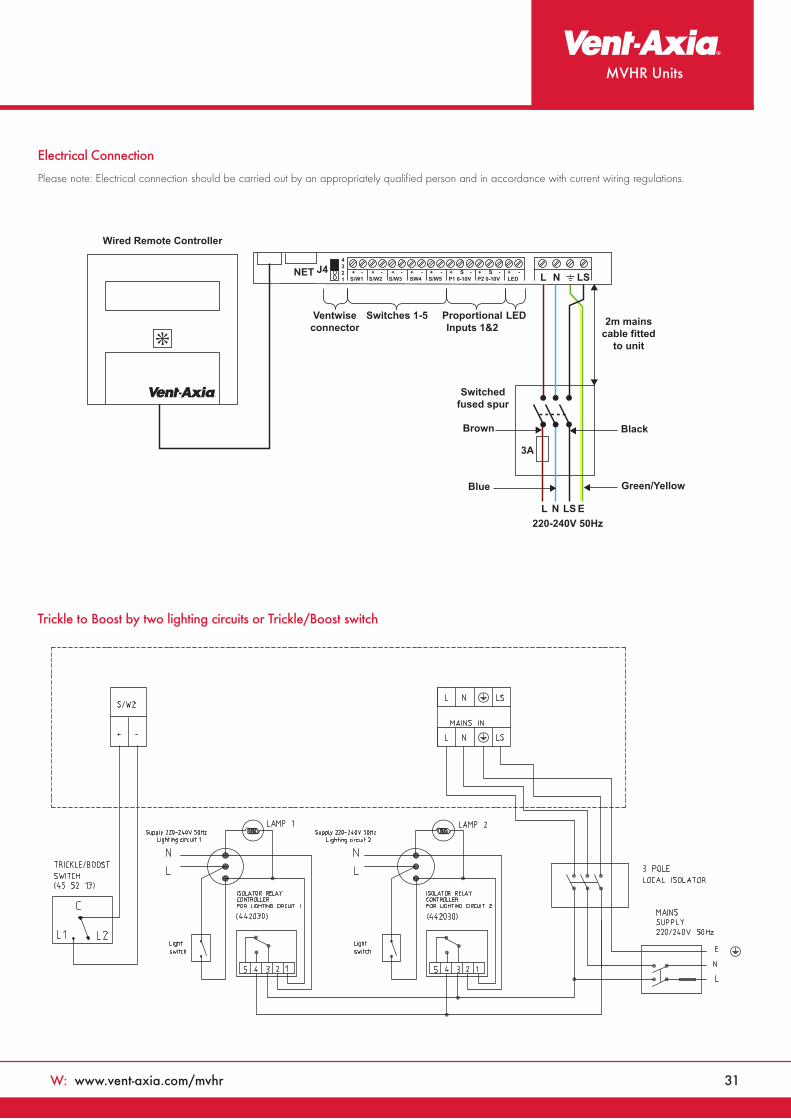
Trickle to Boost by two lighting circuits or Trickle/Boost switch
Electrical Connection
Please note: Electrical connection should be carried out by an appropriately qualified person and in accordance with current wiring regulations.
NET J44321
Ventwiseconnector
Switches 1-5 ProportionalInputs 1&2
LED
3A
2m mainscable fitted
to unit
Brown
Switchedfused spur
Blue
L N LS E220-240V 50Hz
Green/Yellow
Black
S/W1+ - + - + - + - + - + S - + S - + -
S/W2 S/W3 SW4 S/W5 P1 0-10V P2 0-10V LED L N LS
Wired Remote Controller

VENT-AXIA CONTACT NUMBERS
Free technical, installation and sales advice is available
Sales Centre:
Domestic & Commercial
Sales Tel: 0844 856 0590
Sales Fax: 01293 565169
Tech Support Tel: 0844 856 0594
Tech Support Fax: 01293 539209
Heating Support
Sales Tel: 0844 856 0596
Industrial
Sales Tel: 0844 856 0591
Sales Fax: 01293 534898
Tech Support Tel: 0844 856 0595
Tech Support Fax: 01293 455197
Web: www.vent-axia.com
Email: [email protected]
By Appointment to H.M. The QueenSuppliers of Unit Ventilation Equipment
Vent-Axia, Crawley, West Sussex
402351/0315Vent-Axia Group Ltd Products you can trustA British company supporting British manufacturing
Supply & Service
All sales made by Vent-Axia Limited are made only upon
the terms of the Company’s Conditions of Sale, a copy of
which may be obtained on request. As part of the policy of
continuous product improvement Vent-Axia reserves the right
to alter specifications without notice.


