ETJOURNAL oFENGINEERING &TECHNOLOGY Autumn 2010 co N co LO , 0) N N N Z (f) (f) Enhancing Thermal Efficiency of Steam Turbine In Coal Fired Thermal Power Plant Sanjeev Sharma' R. J. Lalwanj2 Introduction Abstract Thispaper describes some options for conservation of energy in the turbine section of a 210MW unit of a coal fired thermal power plant. It shows the need and importance ofenergy conservation. Inthispaper, data is collected from the power plant and analyzed for determining different performance parameters of the turbinesection. Acontinuing concern ofoperators ofsteam turbines is increasing operating costs. These costs reflect not only the rising cost of fuel and material but also the decreased efficiency of the aging turbine fleet. Over time, damage to turbine components and increased steam leakage are the major factors resulting in lost efficiency Steam leakage alone can account for as much as 80 percent of the efficiency losses in turbines. Since the cost of fuel and materials is largely beyond the control of steam turbine operators, the primary mechanism for realizing savings is in the improvement ofturbine efficiency Due to increasing operating costs, the owners and operators of steam electric generation plants work under considerable pressure to maximize the reliability, efficiency and capacity of their plants. In this regard, the single most critical component of the steam electric generation plant is the steam turbine. Most steam turbines operate below optimum efficiency levels by as much as several percentage points due to many factors including damage, deposits, misalignment, unusual flow phenomena and steam leakage. Additionally, reliability is frequently compromised by these factors. Sub-optimum unit performance is becoming increasingly more costly as prices for fuel and materials rise and production competition becomes tougher. Detailed evaluation of the turbine's operating state, and practical selection of performance improvements are critical to optimum operation of the electric generation plant. Application and implementation of state-of- the- art after-market replacement components, along with improved operating procedures and techniques, can lead to significant improvements in reliable performance and sustained optimum efficiency and capacity. Partly due to rising operating costs, as well as an increasingly competitive energy marketplace, steam turbine thermal performance has become an extremely important aspect of the power industry's fleet maintenance programs. Although returning the turbine to its maximum ••..•..• -r----1 Keywords Coal Fired Thermal Power Plant, Steam Turbine,EnergyConservation, ThermalEfficiency 'Asst. Prof (Mechanical Engineering Department.) Skyline Institute of Engineering & Technology, Greater Noida India 'Dean & HOD (Mechanical Engineering Department.) Skyline Institute of Engineering & Technology, Greater Noida India
Thispaper describes some options for conservationof energy in the turbine section of a 210MW unit of acoal fired thermal power plant. It shows the need andimportance of energy conservation. In this paper, datais collected from the power plant and analyzed fordetermining different performance parameters of theturbinesection.
A continuing concern of operators of steam turbines isincreasing operating costs. These costs reflect notonly the rising cost of fuel and material but also thedecreased efficiency of the aging turbine fleet. Overtime, damage to turbine components and increasedsteam leakage are the major factors resulting in lostefficiency Steam leakage alone can account for asmuch as 80 percent of the efficiency losses inturbines. Since the cost of fuel and materials is largelybeyond the control of steam turbine operators, theprimary mechanism for realizing savings is in theimprovement of turbine efficiency
Due to increasing operating costs, the owners
and operators of steam electric generationplants work under considerable pressure tomaximize the reliability, efficiency and capacityof their plants. In this regard, the single mostcritical component of the steam electricgeneration plant is the steam turbine. Moststeam turbines operate below optimumefficiency levels by as much as severalpercentage points due to many factors includingdamage, deposits, misalignment, unusual flowphenomena and steam leakage. Additionally,reliability is frequently compromised by thesefactors. Sub-optimum unit performance isbecoming increasingly more costly as prices forfuel and materials rise and productioncompetition becomes tougher. Detailedevaluation of the turbine's operating state, andpractical selection of performanceimprovements are critical to optimum operationof the electric generation plant. Application andimplementation of state-of- the- art after-marketreplacement components, along with improvedoperating procedures and techniques, can leadto significant improvements in reliableperformance and sustained optimum efficiencyand capacity.
Partly due to rising operating costs, as well as anincreasingly competitive energy marketplace,steam turbine thermal performance has becomean extremely important aspect of the powerindustry's fleet maintenance programs.Although returning the turbine to its maximum ••..•..•-r----1
Keywords Coal Fired Thermal Power Plant, SteamTurbine,EnergyConservation, ThermalEfficiency
'Asst. Prof(Mechanical Engineering Department.)Skyline Institute of Engineering& Technology, Greater NoidaIndia
'Dean & HOD(Mechanical Engineering Department.)Skyline Institute of Engineering& Technology, Greater NoidaIndia
r RSH
rnW
11 12
LPTIPTHPT
7
6
achievable efficiency is one primary goal of themaintenance overhaul, the industry's trendtowards an increased Mean - Time - Between-Overhaul (MTBO) demands new methods forsustaining high efficiency levels over longerperiods of operation. With recent de.velopment ofcutting-edge technologies, sustained highefficiency has become a practical goal of turbineOperations and Maintenance teams [6].
A thorough understanding of actual turbinesefficiency level is important and the authoremphasizes that the nucleus of a turbinemaintenance program should be centeredaround the following inspection and repair/improvement activities:
• Accurate and regular programs ofperformance testing
Regular analysis of test data for identificationoftrends and "events"
• Appraisal of steam path conditions andquantification of damage mechanisms
3
5
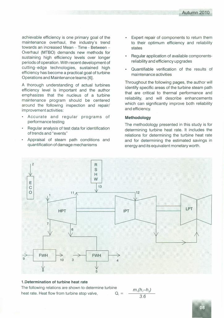
1.Determination of turbine heat rateThe following relations are shown to determine turbineheat rate. Heat flow from turbine stop valve, Q, =
Autumn 2010
Expert repair of components to return themto their optimum efficiency and reliabilitystates
Regular application of available components-reliability and efficiency upgrades
Quantifiable verification of the results ofmaintenance activities
Throughout the following pages, the author willidentify specific areas of the turbine steam paththat are critical to thermal performance andreliability, and will describe enhancementswhich can significantly improve both reliabilityand efficiency.
Methodology
The methodology presented in this study is fordetermining turbine heat rate. It includes therelations for determining the turbine heat rateand for determining the estimated savings inenergy and its equivalent monetary worth.
ETJOURNALoFENGINEERING&TECHNOLOGY
Autumn 2010
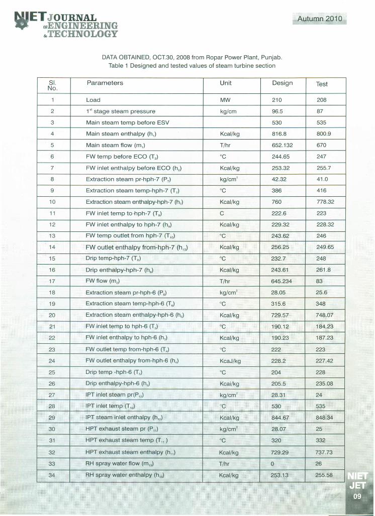
DATA OBTAINED, OCT.30, 2008 from Ropar Power Plant, Punjab.Table 1 Designed and tested values of steam turbine section
SI. Parameters Unit Design TestNo.
1 Load MW 210 208
2 1SI stage steam pressure kg/cm 96.5 87
3 Main steam temp before ESV 530 535
4 Main steam enthalpy (h,) Kcal/kg 816.8 800.9
5 Main steam flow (m,) T/hr 652.132 670
6 FW temp before ECO (T2) °C 244.65 247
7 FW inlet enthalpy before ECO (h,) Kcal/kg 253.32 255.7
34 RH spray water enthalpy (h,,) Kcal/kg 253.13 255.58
h6, m6
FWH6h4 h3m3
h5
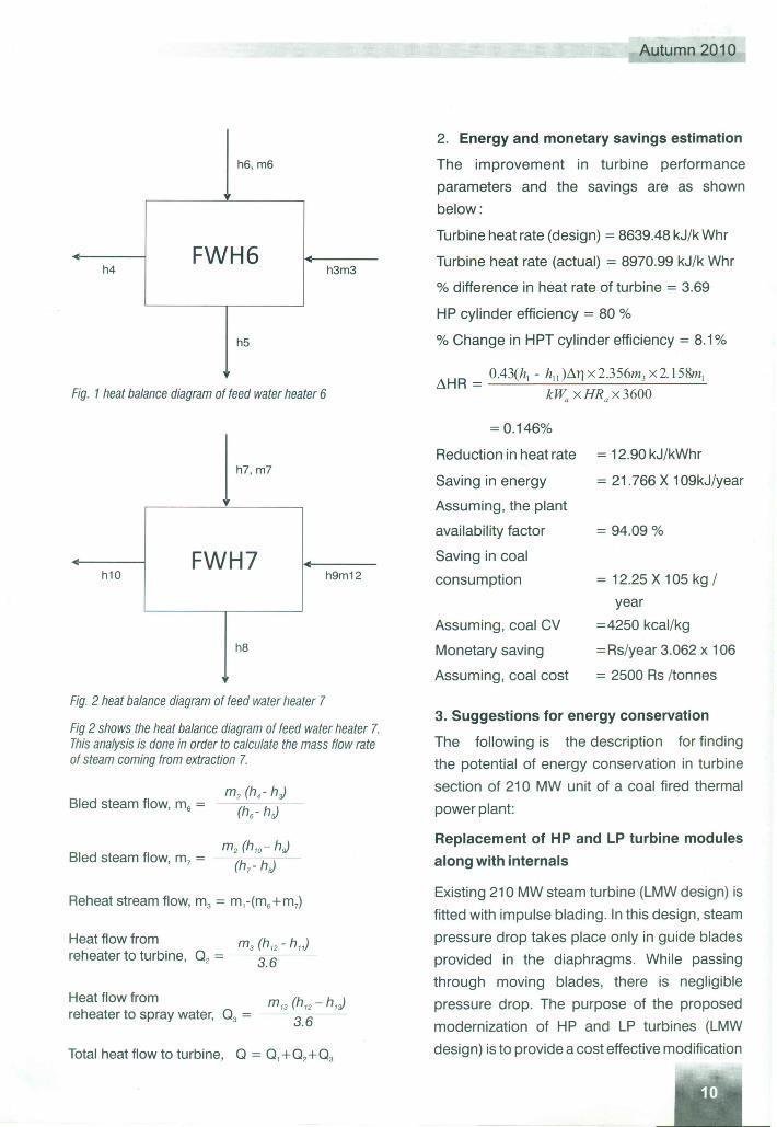
Fig. 1heat balance diagram of feed water heater 6
h10
h8
FWH7h9m12
Fig. 2 heat balance diagram of feed water heater 7
Fig 2 shows the heat balance diagram of feed water heater 7.This analysis is done in order to calculate the mass flow rateof steam coming from extraction 7.
Bled steam flow, rn, =
Bled steam flow, rn, =
Reheat stream flow, m3= m,-(m6+m7)
Heat flow from (h h)m3 '2 - 11
reheater to turbine, Q2 = --3.6
Heat flow fromreheater to spray water, Q3 =
m'3 (h'2 - h,)3.6
Total heat flow to turbine, Q = Q,+Q2+Q3
Autumn 2010
2. Energy and monetary savings estimation
The improvement in turbine performance
parameters and the savings are as shown
below:
Turbine heat rate (design) = 8639.48 kJ/k Whr
Turbine heat rate (actual) = 8970.99 kJ/k Whr
% difference in heat rate of turbine = 3.69
HP cylinder efficiency = 80 %
% Change in HPT cylinder efficiency = 8.1%
= 0.146%
Reduction in heat rate = 12.90 kJ/kWhr
Saving in energy = 21.766 X 10⁹kJ/year
Assuming, the plant
availability factor = 94.09 %
Saving in coal
consumption = 12.25 X 10⁵ kg /
year
=4250 kcal/kg
= Rs/year 3.062 x 106
= 2500 Rs /tonnes
Assuming, coal CV
Monetary saving
Assuming, coal cost
3. Suggestions for energy conservation
The following is the description for finding
the potential of energy conservation in turbine
section of 210 MW unit of a coal fired thermal
power plant:
Replacement of HP and LP turbine modulesalong with internals
Existing 210 MW steam turbine (LMW design) is
fitted with impulse blading. In this design, steam
pressure drop takes place only in guide blades
provided in the diaphragms. While passing
through moving blades, there is negligible
pressure drop. The purpose of the proposed
modernization of HP and LP turbines (LMW
design) is to provide a cost effective modification
ETJOURNALOFENGINEERING&TECHNOLOGY
and upgradation package, to maximize the
improvement in HP and LP turbine performance.
The upgradation of HP and LP turbine is possible
by incorporating the use of improved blade profile
which results into reduction in the aerodynamic
flow losses egoprofile loss, secondary flow loss and
tip leakage loss. After renovation and
modernization of HP and LP turbine by
implementation of the proposal, their life is
expected to be about 25-30 years. Design cylinder
efficiency shall be as under:
HP LP
Old 80% 78%
New 86.5% 80%
The following are the benefits of improved bladeprofile:
A) The improved design and cylinder efficiency
shall help in reducing heat rate.
B) The existing turbine requires large
replacements as per RLA studies and should
have run for more than 1, 50,000 hrs.
C) Life extension
Every type of energy optimization is about
reducing the total cost of a generation, i.e.
reducing the losses in relation to the cost,
either by increasing the thermal efficiency of
the process or the efficiency of its components.
For example, a gain in the isentropic turbine
efficiency is of high interest in the field of steam
turbine research. Various losses related to
blade profiles are:
(I) Profile loss is usually referred to as the loss
generated in the blade boundary layers,
including the loss arising at the trailing edge
[1].
(ii) End-wall loss arises from the annulus
boundary layers, and is sometimes referred to
Autumn 2010
as secondary flow loss to include all the
losses that otherwise are not accounted for
[4].
(iii) Tip leakage loss arises from the leakage flow
over the tips of rotors and the hub clearance
between blade rows and the cavity flow. For
upstream stages, the secondary flow loss
and tip leakage loss also become important,
and for admission stages in small-scale
machines even more significant than the
profile loss [5].
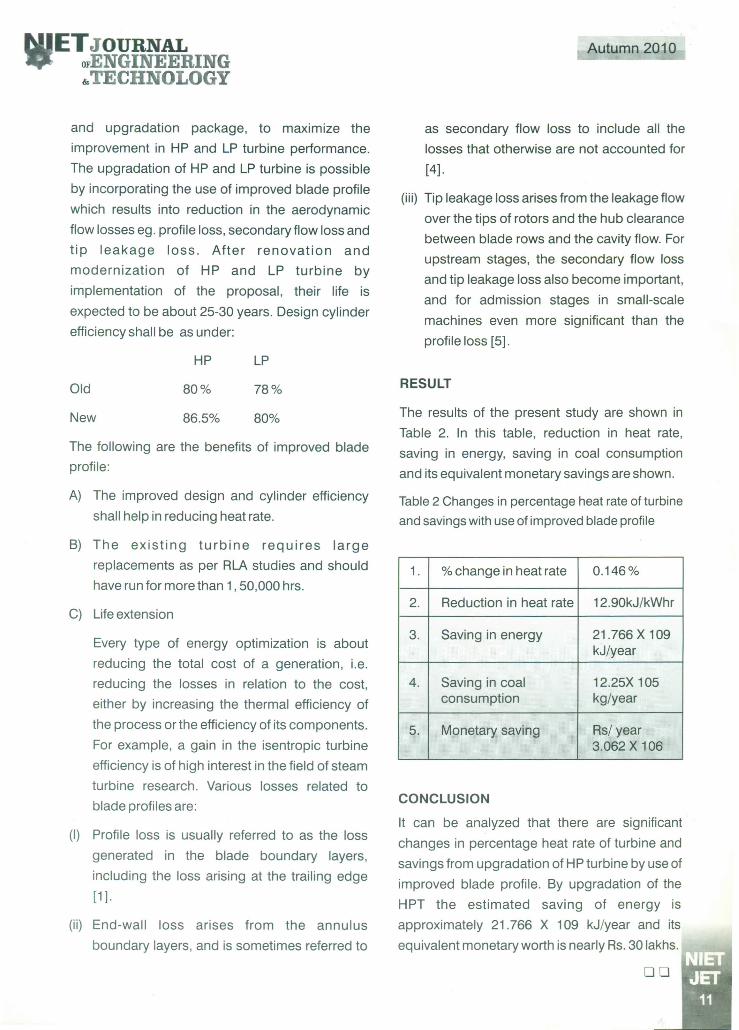
RESULT
The results of the present study are shown in
Table 2. In this table, reduction in heat rate,
saving in energy, saving in coal consumption
and its equivalent monetary savings are shown.
Table 2 Changes in percentage heat rate of turbineand savings with use of improved blade profile
1. % change in heat rate 0.146%
2. Reduction in heat rate 12.90kJ/kWhr
3. Saving in energy 21.766 X 10⁹kJ/year
4. Saving in coal 12.25X 10⁵consumption kg/year
5. Monetary saving Rs/ year3.062 X 106
CONCLUSION
It can be analyzed that there are significant
changes in percentage heat rate of turbine and
savings from upgradation of HP turbine by use of
improved blade profile. By upgradation of the
HPT the estimated saving of energy is
approximately 21.766 X 10⁹ kJ/year and its
equivalent monetary worth is nearly Rs. 30 lakhs. ''''"1I"T"""c::-::l
00
REFERENCES:1. Melvin H. Chiogioji, Industrial Energy Conservation,
5. Hunt G. F.,Modem Power Station Practice, VolumeC, British Electricity International London,Pergamon Press, Oxford, New York, Seoul, Tokyo,1991; 2-13.
6. Arthur P.Fraas, M. Necati Ozisik, Heat ExchangerDesign, John Wily & Sons, Inc. N York, London,Sydney, 1965; 241-255.