LOAD BALANCING AND POWER FACTOR CORRECTION IN POWER DISTRIBUTION SYSTEM Bachelor of Technology in Electrical Engineering BY PUSHANJEET MISHRA (110EE0135) ABHISEK KUMAR PANDA (110EE0587) UNDER SUPERVISION OF PROF. PRAFULLA CHANDRA PANDA DEPARTMENT OF ELECTRICAL ENGINNERINGNATIONAL INSTITUTE OF TECHNOLOGY,ROURKELA
Transcript
LOAD BALANCING AND POWER FACTOR
CORRECTION IN POWER DISTRIBUTION
SYSTEM
Bachelor of Technology in Electrical Engineering
BY
PUSHANJEET MISHRA (110EE0135)
ABHISEK KUMAR PANDA (110EE0587)
UNDER SUPERVISION OF
PROF. PRAFULLA CHANDRA PANDA
DEPARTMENT OF ELECTRICAL ENGINNERINGNATIONAL INSTITUTE OF
TECHNOLOGY,ROURKELA
This report project has been written by myself.
Signature of the Student
Certified that the student has performed the project work under my supervison.
Signature of the Supervisor
CERTIFICATE
This is to certify that the work on the thesis entitled Load balancing and power factor
correction in distribution system by Pushanjeet Mishra and Abhisek Kumar Panda is a
record of original research work carried out under my supervision and guidance for the partial
fulfillment of the requirements for the degree of Bachelor in Technology in the department
of Electrical Engineering, National Institute of Technology, Rourkela. Neither this thesis
nor any part of it has been submitted for the award of any degree elsewhere.
Place: NIT Rourkela Prof. Prafulla Chandra Panda
Date: May, 2014 Professor, Electrical Department
NIT, Rourkela, Odisha
ACKNOWLEDGEMENT
We express our gratitude and sincere thanks to our supervisor Prof. Prafulla Chandra
Panda, Department of Electrical Engineering for his constant motivation and support
during the course of our thesis. We truly appreciate and value his esteemed guidance and
encouragement from the beginning to the end of this thesis. We are indebted to him for
having helped us shape the problem and providing insights towards the solution.
Pushanjeet Mishra(110EE0135)
Abhisek Kumar Panda(110EE0587)
ABSTRACT
The project presents an approach for load balancing and power factor correction. First we
have considered a three phase grounded load system where the supply is a three phase
balanced supply. Before balancing the load and correcting the power factor it is necessary to
compensate the neutral current. We propose three schemes for neutral current balancing.
After that the system becomes equivalent to ungrounded star connected load. Now to carry
power factor correction and load balancing we need to convert the load to delta connected
load. Hence we carry out star-delta transformation and we carry out our main objective
through the proposed methods.
TABLE OF CONTENTS
TOPIC PAGE
ABSTRACT 5
INTRODUCTION 7
BACKGROUND AND LITERATURE
REVIEW
8
METHODOLOGY
System Overview
Neutral Current Compensation of
unbalanced grounded load using
scheme 1, scheme 2 and scheme 3.
Power factor correction and load
balancing of unbalanced load.
11
TABULATION AND CALCULATION 19
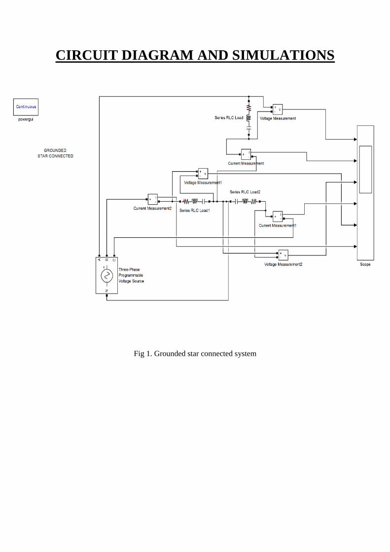
CIRCUIT DIAGRAM & SIMULATIONS 24
CONCLUSION 35
REFERENCES 36
I. INTRODUCTION
For our convenience we require distortion less voltage and current supply. Usually there are
distortions in this waveforms because of the presence of non linear loads.
It is important to compensate reactive power due to non linear loads. Over the years many
methods have been proposed for carrying out this proposed work. Our main aim is to
generate reference current waveform, which will compensate the load harmonics and enhance
the power factor.
Our main objective is to first transform the system from three phase four wire unbalanced
load to three phase three wire unbalanced load and then carry out the necessary power factor
and load balancing calculations. Three different schemes has been proposed for this method
and then a common scheme has been proposed for load balancing and power factor
correction.
II. BACKGROUND AND
LITERATURE REVIEW
Load Compensation
It is necessary to manage the reactive power to improve the power factor and the quality of
supply Load compensation is the major player in it.
The main objectives in load compensation are:
Improved voltage profile
Power factor improvement
Balanced load.
It is important to maintain the voltage profile within +-5% of the rated value. The main
reason for voltage variation is unbalanced parameters in the generation side and consumption
side. If the reactive power that is being consumed is greater than what is being generated then
there is a definite chance of increased voltage levels. But if both of them are equal then the
coltage levels become flat. Hence in order to maintain a flat voltage profile we have to
determine the active power transfer capability of the system and the necessary reactive power
to be compensated has to be carried out using shunt compensating elements i.e either a
capacitor or an inductor.
Power factor correction
An unity power factor is desirable for better economic and technical operation of the system.
Usually p.f correction means to generate reactive power as close as possible to the load which
requires it rather than generate it at a distance and transmit it to the load, as this results not
only in large conductor size but also in increased losses.
Load balancing
A very important concept of load compensation is load balancing. It is desirable to operate
the three phase system under balanced condition as unbalanced operation results in flow of
negative sequence current in the system and is highly dangerous especially for rotating
machines.
An ideal load compensator would perform the following functions,
It would provide controllable and variable reactive power almost instantaneously as
required by the load.
It should operate independently in all three phases.
It should maintain constant voltage at its terminal.
Harmonic distortion
Harmonic distortion is the change in the waveform of the supply voltage from the ideal
sinusoidal waveform. It is caused by the interaction of distorting customer loads with the
impedance of the supply network. Its major adverse effects are the heating of induction
motors, transformers and capacitors and overloading of neutrals. Power factor correction
capacitors can amplify harmonics to unacceptable values in the presence of harmonic
distortion. Standards specify the major harmonic voltages which can occur on the network,
5% total harmonic distortion being typical.
Power system harmonics
Power system harmonics are integer multiples of the fundamental power system frequency.
Power system harmonics are created by non linear devices connected to the power system.
High levels of power system harmonics can create voltage distortion and power quality
problems. Harmonics in power systems result in increased heating in the equipment and
conductors, misfiring in variable speed drives, and torque pulsations in motors.
Active power filters
Active power filters are simply power electronic converters specifically designed to inject
harmonic currents to the system. Active power capabilities include:
Eliminating voltage and current harmonics
Reactive power compensation
Regulating terminal voltage
Compensating the voltage flickering
III. METHODOLOGY
III.I System Overview:
In our system we have considered a balanced three phase supply feeding the unbalanced load.
The supply voltages are taken as:
Va= |V|∟0 Vb=|V|∟120 Vc=|V|∟240.
First we have considered a three phase unbalanced grounded load system, we present three
schemes for neutral current compensation and then three-phase three wire unbalanced load
will be compensated using a common scheme. For the first scheme we consider phase b and
c, second scheme selects phase a and b and third scheme selects phase a and c for neutral
current compensation. The current carried away by neutral, Ineutral is given by the summation
of Ina, Inb, In0. Ineutral will be neutralized by injecting a current equal in magnitude and 180
degrees out of phase from where stands for neutral current compensating current.
The load becomes equivalent to three phase three wire unbalanced load after neutral current
compensation, this system is then transformed to equivalent delta connection. We select two
sets of compensating elements, one for power factor correction and the other for load
balancing of this equivalent delta connection.
III.II Neutral current compensation of three phase unbalanced grounded loads
III.II.I Scheme 1:
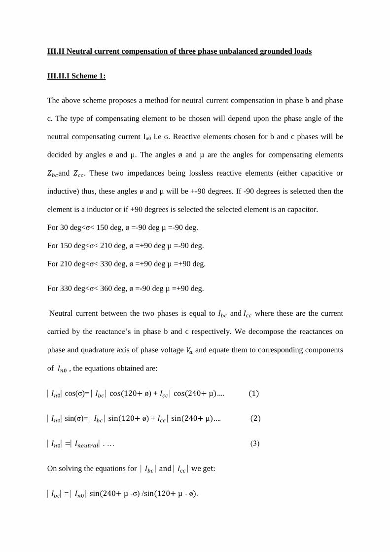
The above scheme proposes a method for neutral current compensation in phase b and phase
c. The type of compensating element to be chosen will depend upon the phase angle of the
neutral compensating current In0 i.e σ. Reactive elements chosen for b and c phases will be
decided by angles ø and µ. The angles ø and µ are the angles for compensating elements
and . These two impedances being lossless reactive elements (either capacitive or
inductive) thus, these angles ø and µ will be +-90 degrees. If -90 degrees is selected then the
element is a inductor or if +90 degrees is selected the selected element is an capacitor.
For 30 deg<σ< 150 deg, ø =-90 deg µ =-90 deg.
For 150 deg<σ< 210 deg, ø =+90 deg µ =-90 deg.
For 210 deg<σ< 330 deg, ø =+90 deg µ =+90 deg.
For 330 deg<σ< 360 deg, ø =-90 deg µ =+90 deg.
Neutral current between the two phases is equal to and where these are the current
carried by the reactance’s in phase b and c respectively. We decompose the reactances on
phase and quadrature axis of phase voltage and equate them to corresponding components
of , the equations obtained are:
cos(σ)= cos(120+ ø) + cos(240+ µ)…. (1)
sin(σ)= sin(120+ ø) + sin(240+ µ)…. (2)
= . … (3)
On solving the equations for and we get:
= sin(240+ µ -σ) /sin(120+ µ - ø).
= sin(120+ ø -σ) /sin(-µ + ø -120).
We obtain the below susceptances:
= sin(ø)/V mag.
= sin(µ)/V mag.
The above susceptances are put across phase b and phase c and the system neutral current is
+ + + + =0.
Neutral compensated load now becomes equivalent to:
= ; = . /( + ); = . /( + ).
III.II.II Scheme 2:
This scheme below provides neutral current compensation in phases a and b for a 3 phase 4
wire unbalanced load. The reactive elements will be placed in phases a and b for neutral
current compensation. The angle λ and ø are the angles of lossless reactive elements that are
to be connected across phase a and phase b for neutral current compensation and may be
either +900
or -900. Angles λ and ø will depend on the value of σ as follows.
For 300<σ<90
0, λ=+90
0, ø=-90
0
For 900<σ<210
0, λ=+90
0, ø=+90
0
For 2100<σ<270
0, λ=-90
0, ø=+90
0
For 2700<σ<360
0, λ=-90
0, ø=-90
0
If angle λ or ø is positive then capacitor if negative then inductor will be connected in the
respective phases. These reactive elements will carry phase currents Iac and Ibc in phases a and
b respectively. The currents Iac and Ibc are decomposed along phase and quadrature axis and
the equations obtained are as follows:
In0cosσ= Iaccosλ + Ibccos(120+ø);….. (1)
In0sinσ= Iacsinλ + Ibcsin(120+ø);…. (2)
Neutral current in compensating phases a and b is given by Iac and Ibc. On solving above
equations:
Iac=In0sin(120+ø-σ)/sin(1200+ø-λ);
Ibc=In0sin(λ-σ)/sin(λ-ø-1200);
Iac=Iac<λ; Zac=V/Iac;
Ibc=Ibc<(120+ø); Zbc=V/Ibc;
The corresponding susceptances are Bac=Iacsin(λ/V); Bac=Ibcsin(ø/V)
The values of Zac and Zbc make the system equivalent to three phase ungrounded star
connected. Supply neutral current becomes zero as:
Ial + Ibl + Icl+ Iac+ Ibc=0
Equivalent neutral compensated load now becomes:
Za=ZalZac/(Zal+Zac); Zb=ZblZbc/(Zbl+Zbc); Zc=Zcl.
III.II.III Scheme 3:
The below scheme considers phases a and c for neutral current compensation. The values and
type of susceptances to be connected across phase a and c will depend upon the following
method:
For 00<σ<90
0 and 330
0<σ<360
0, λ=+90
0, µ=-90
0
For 900<σ<150
0, λ=+90
0, µ=-90
0
For 1500<σ<270
0, λ=-90
0, µ=-90
0
For 2700<σ<330
0, λ=-90
0, ø=+90
0
On decomposing the currents along phase and quadrature axis we obtain the following
equations:
In0cosσ=Iaccosλ+Icccos(2400+µ);….. (1)
In0sinσ=Iacsinλ+Iccsin(2400+µ);…… (2)
In0=Ineutral…… (3)
Solving the above equations we obtain:
Iac=In0sin(240+µ-σ)/sin(240+µ-λ);
Icc=Iasin(λ-σ)/sin(λ-µ-2400);
Iac=Iac<λ; Zac=V/Iac;
Icc=Icc<(2400+µ); Zcc=V/Icc;
The susceptances obtained are Bac=Iacsin(λ/V); Bcc=Iccsin(µ)/V. The above values of Zac and
Zcc make the system equivalent to three phase ungrounded star connected. Supply neutral