3. Primary structure according to structural design4. Fastener in every flange against support
Date
Scale
Drawn by
Rev.Drw. nr.
File nr.
Rev. date
Building
Rev.
Work nr.
Contents of drawing
IN 11IN00A401118.10.2005
Ruukki
.
07.04.2011
.
IN00A4011
L L L L L
L L L L L
X1 X2 X2 X12.
1.
L L L L L
X3 X43.
L L L L
4.
X3X4
X3 X4 X1
Attention:X1 = 0,125 x LX2 = 0,146 x LX3 = 0,204 x LX4 = 0,157 x LL - span length
Rautaruukki Corporation.CCopyright
A
A
Static scheme
A
Detail A drawing no IN 12
Load-bearing sheets - insulated profilesErection - Gerber system
01
Date
Scale
Drawn by
Rev.Drw. nr.
File nr.
Rev. date
Building
Rev.
Work nr.
Contents of drawing
IN00A401212.09.2005
Ruukki
1:5
07.04.2011
.
IN00A4012
min 150 mm1
1
1
75 mm 75 mm
4
5
min 3d
5
4
Rautaruukki Corporation.CCopyright
IN 12
Standard endlap of load-bearing sheets - Gerber system - insulated roof
2
3
Detail A
Section X - X
* - lenght, type of endlap, number of screws according to structural design
Section Y-Y drawing no IN 02
1 1
d-diameter of screw
Load-bearing sheets - insulated roofErection - Gerber system (endlap)
01
2. Primary structure according to structural design3. Fastener in every flange against support
1. Ruukki load-bearing sheet
4. Fastener5. Fastener for estetical reasons
Attention:
Scale
Drawn by
Rev.Drw. nr.
File nr.
Rev. date
Building
Rev.
Work nr.
Contents of drawing
IN00A401312.09.2005
Ruukki
1:5
07.04.2011
.
IN00A4013
Rautaruukki Corporation.CCopyright
IN 13
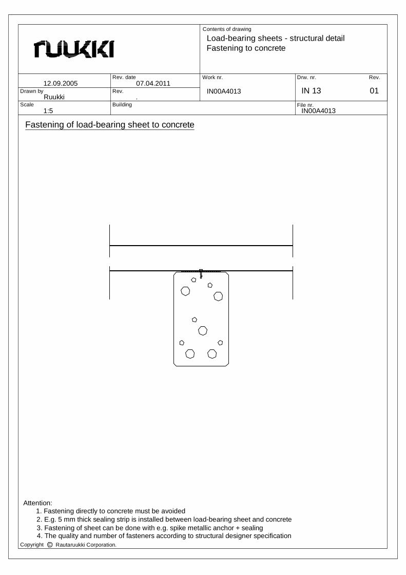
Fastening of load-bearing sheet to concrete
Load-bearing sheets - structural detailFastening to concrete
01
3. Fastening of sheet can be done with e.g. spike metallic anchor + sealing4. The quality and number of fasteners according to structural designer specification
2. E.g. 5 mm thick sealing strip is installed between load-bearing sheet and concrete1. Fastening directly to concrete must be avoided
Attention:
Scale
Drawn by
Rev.Drw. nr.
File nr.
Rev. date
Building
Rev.
Work nr.
Contents of drawing
IN00A401412.09.2005
Ruukki
1:5
07.04.2011
.
IN00A4014
Rautaruukki Corporation.CCopyright
IN 14
Fastening of load-bearing sheet to concrete/wood
Load-bearing sheets - structural detailFastening to concrete/wood
01
2. Load-bearing sheet is fastened to wood e.g. with self-drilling wood screws3. The quality and number of fasteners according to structural designer specification
1. Wood is installed onto concrete structure, fastening e.g. with wedge anchorsAttention:
Scale
Drawn by
Rev.Drw. nr.
File nr.
Rev. date
Building
Rev.
Work nr.
Contents of drawing
IN00A401512.09.2005
Ruukki
1:5
07.04.2011
.
IN00A4015
Rautaruukki Corporation.CCopyright
IN 15
Fastening of load-bearing sheet to prestressed concrete structures
Load-bearing sheets - structural detailFastening to prestressed concrete structures
01
2. Load-bearing sheet is fastened to steel profile with e.g. self-drilling screws3. The quality and number of fasteners according to structural designer specification
1. Steel profile is installed onto concrete structure, fastening to fastening plates in the prestressed concrete structure
steel profile, non continuousrectangular hollow section orcold worked U-steel
t
Attention:
Scale
Drawn by
Rev.Drw. nr.
File nr.
Rev. date
Building
Rev.
Work nr.
Contents of drawing
IN00A401612.09.2005
Ruukki
1:5
07.04.2011
.
IN00A4016
Rautaruukki Corporation.CCopyright
IN 16
Load-bearing sheets - structural detailFastening to prestressed concrete structures
01
2. Load-bearing sheet is fastened to wood with e.g. self-drilling wood screws3. The quality and number of fasteners according to structural designer specification
concrete structure with coach screws1. Wood is installed onto concrete structure, fastening to steel plates welded to fastening plates in the prestressed
Fastening of load-bearing sheet to prestressed concrete structures
woodnon continuous
Attention:
Date
Scale
Drawn by
Rev.Drw. nr.
File nr.
Rev. date
Building
Rev.
Work nr.
Contents of drawing
IN 17IN00A401718.10.2005
Ruukki
1:5
07.04.2011
.
IN00A4017
Profile T45
Profile T60
Profile T55
1
1
1
2
2
2
* - flange and fastener number according to structural design
FIRE PROTECTION, WHEN NECESSARYLOAD-BEARING PROFILED SHEET ACCORDING TO CONSTRUCTION DRAWING
VAPOUR BARRIER, NET REINFORCED ALUMINIUM COATED PLASTIC,THERMAL INSULATIONTHERMAL INSULATION, SUITED FOR WATER INSULATION'S BASEWATER INSULATION
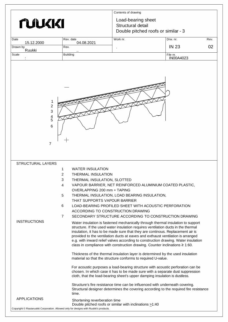
STRUCTURAL LAYERS
APPLICATIONS
OVERLAPPING 200 mm + TAPING
67
5
43
12
Water insulation is fastened mechanically through thermal insulation to supportstructure. If the used water insulation requires ventilation ducts in the thermalinsulation, it has to be made sure that they are continous. Replacement air isprovided to the ventilation ducts at eaves and exthaust ventilation is arrangede.g. with inward relief valves according to construction drawing. Water insulationclass in compliance with construction drawing. Counter inclinations ≥ 1:60.
Thickness of the thermal insulation layer is determined by the used insulationmaterial so that the structure conforms to required U-value.
For acoustic purposes a load-bearing structure with acoustic perforation can bechosen. In which case it has to be made sure with a separate dust suppressioncloth, that the load-bearing sheet's upper damping insulation is dustless.
Structure's fire resistance time can be influenced with underneath covering.Structural designer determines the covering according to the required fire resistancetime.
PROTECTIVE GRAVEL, d= 8...20, >35 kg/m2WATER INSULATIONTHERMAL INSULATIONTHERMAL INSULATION, SLOTTEDVAPOUR BARRIER, NET REINFORCED ALUMINIUM COATED PLASTIC,OVERLAPPING 200 mm + TAPING
LOAD-BEARING PROFILED SHEET WITH ACOUSTIC PERFORATIONACCORDING TO CONSTRUCTION DRAWING
Flat roofs with inclinations 1:20-1:40APPLICATIONS
Water insulation is fastened mechanically through thermal insulation to supportstructure. If the used water insulation requires ventilation ducts in the thermalinsulation, it has to be made sure that they are continous. Replacement air isprovided to the ventilation ducts at eaves and exthaust ventilation is arrangede.g. with inward relief valves according to construction drawing. Water insulationclass in compliance with construction drawing. Counter inclinations ≥ 1:60.
Thickness of the thermal insulation layer is determined by the used insulationmaterial so that the structure conforms to required U-value.
For acoustic purposes a load-bearing structure with acoustic perforation can bechosen. In which case it has to be made sure with a separate dust suppressioncloth, that the load-bearing sheet's upper damping insulation is dustless.
Structure's fire resistance time can be influenced with underneath covering.Structural designer determines the covering according to the required fire resistancetime.
WATER INSULATIONTHERMAL INSULATIONTHERMAL INSULATION, SLOTTEDVAPOUR BARRIER, NET REINFORCED ALUMINIUM COATED PLASTIC,OVERLAPPING 200 mm + TAPING
FIRE PROTECTION, WHEN NECESSARY
Double pitched roofs or similar with inclinations >1:40
LOAD-BEARING PROFILED SHEET ACCORDING TO CONSTRUCTION DRAWING
Water insulation is fastened mechanically through thermal insulation to supportstructure. If the used water insulation requires ventilation ducts in the thermalinsulation, it has to be made sure that they are continous. Replacement air isprovided to the ventilation ducts at eaves and exthaust ventilation is arrangede.g. with inward relief valves according to construction drawing. Water insulationclass in compliance with construction drawing. Counter inclinations ≥ 1:60.
Thickness of the thermal insulation layer is determined by the used insulationmaterial so that the structure conforms to required U-value.
For acoustic purposes a load-bearing structure with acoustic perforation can bechosen. In which case it has to be made sure with a separate dust suppressioncloth, that the load-bearing sheet's upper damping insulation is dustless.
Structure's fire resistance time can be influenced with underneath covering.Structural designer determines the covering according to the required fire resistancetime.
WATER INSULATIONTHERMAL INSULATIONTHERMAL INSULATION, SLOTTEDVAPOUR BARRIER, NET REINFORCED ALUMINIUM COATED PLASTIC,OVERLAPPING 200 mm + TAPING
LOAD-BEARING SHEET WITH ACOUSTIC PERFORATION
SECONDARY STRUCTURE ACCORDING TO CONSTRUCTION DRAWING7ACCORDING TO CONSTRUCTION DRAWING
APPLICATIONS Shortening reverberation time
Water insulation is fastened mechanically through thermal insulation to supportstructure. If the used water insulation requires ventilation ducts in the thermalinsulation, it has to be made sure that they are continous. Replacement air isprovided to the ventilation ducts at eaves and exthaust ventilation is arrangede.g. with inward relief valves according to construction drawing. Water insulationclass in compliance with construction drawing. Counter inclinations ≥ 1:60.
Thickness of the thermal insulation layer is determined by the used insulationmaterial so that the structure conforms to required U-value.
For acoustic purposes a load-bearing structure with acoustic perforation can bechosen. In which case it has to be made sure with a separate dust suppressioncloth, that the load-bearing sheet's upper damping insulation is dustless.
Structure's fire resistance time can be influenced with underneath covering.Structural designer determines the covering according to the required fire resistancetime.
WATER INSULATIONTHERMAL INSULATIONTHERMAL INSULATION, SLOTTEDVAPOUR BARRIER, NET REINFORCED ALUMINIUM COATED PLASTIC,OVERLAPPING 200 mm + TAPING
LOAD-BEARING PROFILED SHEET WITH ACOUSTIC PERFORATION
SECONDARY STRUCTURE ACCORDING TO CONSTRUCTION DRAWING7ACCORDING TO CONSTRUCTION DRAWING
APPLICATIONS Shortening reverberation time
Water insulation is fastened mechanically through thermal insulation to supportstructure. If the used water insulation requires ventilation ducts in the thermalinsulation, it has to be made sure that they are continous. Replacement air isprovided to the ventilation ducts at eaves and exthaust ventilation is arrangede.g. with inward relief valves according to construction drawing. Water insulationclass in compliance with construction drawing. Counter inclinations ≥ 1:60.
Thickness of the thermal insulation layer is determined by the used insulationmaterial so that the structure conforms to required U-value.
For acoustic purposes a load-bearing structure with acoustic perforation can bechosen. In which case it has to be made sure with a separate dust suppressioncloth, that the load-bearing sheet's upper damping insulation is dustless.
Structure's fire resistance time can be influenced with underneath covering.Structural designer determines the covering according to the required fire resistancetime.
WATER INSULATIONTHERMAL INSULATIONTHERMAL INSULATION, SLOTTEDVAPOUR BARRIER, NET REINFORCED ALUMINIUM COATED PLASTIC,OVERLAPPING 200 mm + TAPING
6 LOAD-BEARING PROFILED SHEET WITH ACOUSTIC PERFORATIONACCORDING TO CONSTRUCTION DRAWING, WOOL BACKFILL IN FLANGES
Shortening reverberation timeAPPLICATIONS
Water insulation is fastened mechanically through thermal insulation to supportstructure. If the used water insulation requires ventilation ducts in the thermalinsulation, it has to be made sure that they are continous. Replacement air isprovided to the ventilation ducts at eaves and exthaust ventilation is arrangede.g. with inward relief valves according to construction drawing. Water insulationclass in compliance with construction drawing. Counter inclinations ≥ 1:60.
Thickness of the thermal insulation layer is determined by the used insulationmaterial so that the structure conforms to required U-value.
For the acoustic purposes, a load-bearing structure with acoustic perforation can bechosen. Also, acoustic infill is recommended to confirm the required absorptionclass (A-E). A separate dust suppression cloth is recommended to prevent anyinsulation wool dust from entering the inside room.
Structure's fire resistance time can be influenced with underneath covering.Structural designer determines the covering according to the required fire resistancetime.
INSTRUCTIONS
Double pitched roofs or similar with inclinations >1:40
VENTILATING STEEL BATTENTHERMAL INSULATIONTHERMAL INSULATIONVAPOUR BARRIER, NET REINFORCED ALUMINIUM COATED PLASTIC,OVERLAPPING 200 mm + TAPING
(ACOUSTIC PERFORATION, WOOL BACKFILL IN FLANGES, WHEN NECESSARY)LOAD-BEARING PROFILED SHEET ACCORDING TO CONSTRUCTION DRAWING7
Water insulation is fastened mechanically through thermal insulation to supportstructure. If the used water insulation requires ventilation ducts in the thermalinsulation, it has to be made sure that they are continous. Replacement air isprovided to the ventilation ducts at eaves and exthaust ventilation is arranged e.g.with inward relief valves according to construction drawing. Water insulation class incompliance with construction drawing.
Thickness of the thermal insulation layer is determined by the used insulationmaterial so that the structure conforms to required U-value.
For acoustic purposes a load-bearing structure with acoustic perforation can bechosen. In which case it has to be made sure with a separate dust suppressioncloth, that the load-bearing sheet's upper damping insulation is dustless. The fireprotection wool also acts like acoustic insulation.
Structure's fire resistance time can be influenced with underneath covering. Also theacoustic infill increases the fire resistance time. Structural designer determines thecovering according to the required fire resistance time.
Double pitched roofs or similar with inclinations >1:10APPLICATIONS
WATER INSULATIONTHERMAL INSULATION, SUITED FOR WATER INSULATION'S BASELOAD-BEARING PROFILED SHEET ACCORDING TO CONSTRUCTION DRAWING,
PURLIN STRUCTURE ACCORDING TO CONSTRUCTION DRAWINGLOAD-BEARING STEEL STRUCTURE ACCORDING TO CONSTRUCTION DRAWING
ANTI-CONDENSATION COATING ON THE SHEET'S LOWER SURFACE,
STRUCTURAL LAYERS
INSTRUCTIONS
Warehouse roofs, inclinations >1:40APPLICATIONS
Water insulation is fastened mechanically through thermal insulation to supportstructure. If the used water insulation requires ventilation ducts in the thermalinsulation, it has to be made sure that they are continous. Replacement air isprovided to the ventilation ducts at eaves and exthaust ventilation is arrangede.g. with inward relief valves according to construction drawing. Water insulationclass in compliance with construction drawing. Counter inclinations ≥ 1:60.
Thickness of the thermal insulation layer is determined by the used insulationmaterial so that the structure conforms to required U-value.
WATER INSULATIONTHERMAL INSULATION, SUITED FOR WATER INSULATION'S BASELOAD-BEARING PROFILED SHEET ACCORDING TO CONSTRUCTION DRAWING,
LOAD-BEARING STEEL STRUCTURE ACCORDING TO CONSTRUCTION DRAWING
ANTI-CONDENSATION COATING ON THE SHEET'S LOWER SURFACE,
STRUCTURAL LAYERS
INSTRUCTIONS
Warehouse roofs, inclinations >1:40APPLICATIONS
Water insulation is fastened mechanically through thermal insulation to supportstructure. If the used water insulation requires ventilation ducts in the thermalinsulation, it has to be made sure that they are continous. Replacement air isprovided to the ventilation ducts at eaves and exthaust ventilation is arrangede.g. with inward relief valves according to construction drawing. Water insulationclass in compliance with construction drawing. Counter inclinations ≥ 1:60.
Thickness of the thermal insulation layer is determined by the used insulationmaterial so that the structure conforms to required U-value.