1. General These valves are pressure valves according to the Industrial Standard ISO 1219-1. They prevent pulling or pushing loads from accelerating uncontrollably during movements in load direction, or from proceeding with higher speed than intended i.e. determinedby the inflowing oil on the pump’s side. Consequently, these devices prevent a collapse or eventual rupture of the oil column. Themain application for load-holding valves is with hydraulic lifting-, pivoting-, turning- or similar constructions which utilize double acting consumers (hydraulic cylinders, hydraulic motors).This is accomplished by throttling of the return flow from the corresponding consumer. The load-holding valves generates a flow resistance, which is always a little bit higher than the pressure created from the load. This back pressure is only generated under negative load conditions. But the valve will be fully opened, enabling free flow (return) if the load is positive, i.e. the load acts against the direction of the motion.The throttle device is self-adjusting and therefore adapts continuously to any alternation of the load condition. This is achieved byan equilibrium of forces between the outflow and inflow (from the actuated consumer) acting on the functional valve elements onthe one side, and the valve spring acting on the other side.The valves version LHDV are especially designed for those applications, which, due to their own elasticity, tend heavily towards pendulum oscillations. The load-holding valves are most advantageous when utilized in conjunction with prop. directional spool valvebanks, functioning according to the Load-Sensing-Principle which do have 2-way inflow control valves in each valve bank section. Consequently, they should be installed in the corresponding lines between consumer and directional spool valve.As a self-contained unit, the LHDV-valve permits the specific intervention into the oscillating circle, as it is created by hydraulic cylinders with attached load, the flow control valves of the directional spool valves, or the pressure/flow regulator of variable displacement pump. Its dampening abilities are significantly more adaptable and their effect more accurately adjustable than wouldbe possible with common measurements, e.g. through modification (distortion) of the characteristic curve of the flow control valvesinstalled in prop. directional spool valves.The fluctuating load pressure influences the motion of the control device which varies the throttle area. But its response is slightly delayed, slowed and weakened by a combination of especially designed damping elements. This will successfully intercept the pendulum motions being evoked, which are induced by starting, stopping, or sudden transitions from full speed to crawl speed. They will be eventually suppressed in their developing stage, by letting them fade away quickly. For a detailed functional descrip-tion and notes for customizing the damping, especially for critical conditions, see B 7770.
Proportional directional spool valve bank (size 3)Type PSV acc. to D 7700-3
Variable displacement axial piston pumpType V30D acc. to D 7960
D 7770 page 2
2. Available versions, main data
Version with shock valve, mounted by banjo bolt H = M 22x1.5 or H 1/2 - G 1/2 A (consumer side). It may be installed in any angel concentric around the V-port. A centering predestal is required at the mounting area, see dimensional drawings sect. 4
Order examples:
LHDV 33 P - 15 - B 6 - 300/320 Desired pressure setting (bar) within the permissible pressurerange, acc. to sect. 3For correct positioning of pressure figures for the load holdingvalve, and eventual shock valve see following examples.
2) With positively actingload, i.e. during lifting,one can expect a |p ofapprox. 50 bar with themax. permissible flowrates. This pressurehas to be added to theload pressure.
Single valves for always constant load direction
Release for direction V → F during lowering of the load via an external control line at port Sfrom the other side (inflow consumer line).Order examples of available versions:
Selected pressure setting (bar)load holding valve
LHDV 33 P -11 - C6 - 280Basic type, currently only available for manifold mounting (consumer side). For an adapter plate,enabling pipe connection on the consumer side, see sect. 4, page 5
Load holding valveShock valve
Selected pressuresetting (bar)
LHDV 33 P(H) -15
LHDV 33 P(H) -11
LHDV 33 P -15 - B6 - 300/320Version with shock valve, currently only available for manifold mounting (consumer side). Foran adapter plate, enabling pipe connection on the consumer side, see sect. 4, page 5.
LHDV 33 H -15 - A6 - 200/240
1) The actual release ratio corresponds to the geometric ratio
See also the |p-Q curves in sect. 3,this applies also to the flow / backpressure V→ F with positive load(valve completely open)
Table 1: Basic type, size, and additional elements
Flow patternsymbols, for
illustrationsee sect.
2.1
Single valves forconstant load directions
Double valves for alternating load direction
Without With shuttle valves for the pressure signal port X(T)additionalelements
With suction port T (volume balance)
With by-pass check valve in port X
Basic typeDesign
With add.shock-valves
Banjo boltmounting,consumerside
Standard
LHDV 33 -
LHDV 33 P -
LHDV 33 H -
LHDV 33 H 1/2 -
11 3) 21 21W 21WD ---
With unpressurized -- 21L 21WL --- ---control piston
15 3) 25 25W 25WD 25WDN
With unpressurized -- 25L 25WL 25WDL 25WDNLcontrol piston
Pipe connection 4) --- ' ' ' '
Manif. mounting, cons. side '
M22x1,5 metric fine thread 'DIN 13 T6
G 1/2 A 4) '
2.1 Additional order examples with corresponding flow pattern symbols
3) Port Z is unplugged ex-works (see following flow pat-tern symbol). It may be blocked later, if not requiredby a tapped plug DIN 908-G 1/4 A-St with seal ring14x18x1.5 DIN 7603-CU
4) DIN ISO 228/1 (BSPP)
1)
(Standard)
D 7770 page 3
Like version 25 WD, but with additional suction valve No. 7770 040 intended for hydraulic motors to balance volumes, altered by leakage. Symbol for version LHDV 33 -25 WDNL with additional leakage port,similar to LHDV 33 - 21L...
Double valve for alternating load directions
The release of the respective reflow side V1 → F1 or V2 → F2 takes place via internal control oil ducts. No external control pipes are required.
Oreder examples of available versions:
Over center valve setting (bar)Consumer side V1
Consumer side V2
LHDV 33 - 21 - A6 - 240/180
LHDV 33 - 21W(WD) - A6 - 240/180Like the above basic version, but with additional shuttle valve (see alsodescription of type LHDV 33 - 25W(WD))
LHDV 33 - 21 - A6 - 240/180
LHDV 33 - 21 L - A6 - 240/180
Flow and orificecombinationcoding, see table2 and 3 as wellas functional description in B 7770
LHDV 33 - 25 - D5 - 220/220 - 260/260
Over center valve setting (bar)Consumer side V1Consumer side V2
Shock valve setting (bar)Consumer side V1Consumer side V2
Basic version with shock valves e.g. for consumers with a piston area ratio of 1:1.Flow pattern symbol for version LHDV 21-25L with additional oil leakage port, similar to LHDV 33 - 21L...
LHDV 33 - 25W - A6 - 250/250 - 300/300
Like the basic version 25, but with additional shuttle valve, e.g. for brakeswith hydraulic release (port X). Preferably used for hydraulic motors.Flow pattern symbol for version LHDV 33-25WL with additional leakage port, similar to LHDV 33 - 21L...
LHDV 33 - 25WD - C6 - 100/140 - 130/180
Like version 25 W, but with additional by-pass check valve type BC1-40 E acc. to D 6969 B mounted at port X (intended to prevent sud-den kicking-in of the brake).Flow pattern symbol for version LHDV 33-25 WDL with additional leak-age port, similar to LHDV 33 - 21L...
LHDV 33 - 25WDN - B6 - 200/200 - 240/240
Basic version for all applications, where no high pressure peaks or sudden user stops (shock pressure) are expected.
LHDV 33 - 21L - A6 - 240/180Like the above basic version, but with additional port for leakage oil(see also notes in sect. 5.2).
D 7770 page 4
Designation Load holding valve (over center valve), with hydraulic release and by-pass check valve
Ports F, F1, F2, V, V1, V2 and R Main portsM, S, Z Control- and probing ports depending on version
Mass (weight) approx. Type LHDV 33 P-11 = 1.3 kg LHDV 33-21(21W) = 3.5 kg LHDV 33-25WD = 4.0 kgLHDV 33 P-15 = 1.8 kg 1) LHDV 33-21L (21WL) = 3.5 kg LHDV 33-25WDN = 4.7 kgLHDV 33 H-11 = 1.7 kg LHDV 33-21WD = 3.6 kg LHDV 33-25WDNL = 4.8 kgLHDV 33 H-15 = 2.2 kg LHDV 33-25 (L, W, WL) = 3.9 kg
1) Corresponding connection block No. 7770 024 = 0.4 kg
Flow direction Working direction (load holding function) V → F, V1 → F1 or V2 → F2free flow F → V, F1 → V1, F2 → V2
Release ratio approx. 1:8.2 with closed valve (geometrical ratio)approx. 1:1.2 to 1:6.4 with open (unlocked) valve, depending on the orifice diameter ratio, see sect. 2, table 3
Pressure adjustment A pressure gauge should be used whenever the pressure setting is adjusted or altered! The given figures for pressure alternation per rotation or per mm adjustment travel of the perforated disc withinthe connector F (F1 and F2) are only a rough guide line for approximately achieving the desired setting(start of operation). The setting should be at least 10% above the max. expected load pressure.
3. Further characteristic data
Functional restrictions
The double valves, flow pattern symbol 21... and 25..., cannot be utilized with directional valves, which show theflow characteristics of a differential circuit in one position, e.g. coding C in pamphlet D 5700. Single valves, flowpattern symbols 11 or 15, must not be connected to the rod side of hydraulic cylinders.
Alternation of pressure approx.: per turn per mm approx.
Load holding valve pressure range 50 ... 250 bar 45 bar 25 bar pressure range 220 ...350 bar 50 bar 27.5 bar pressure range 280 .. 420 bar 62 bar 34 bar
Shock valve pressure range 50 ... 250 bar 106 bar 80 bar
Pressure fluid Hydraulic oil according to DIN 51 524, table 1 to 3; ISO VG 10 to 68 according to DIN 51 519range of viscosity: min. approx. 4; max. approx. 1500 mm2/sec; optimum range: approx. 10...500 mm2/secAlso usable for biodegradable pressure fluids of the type HEPG (Polyalcylenglycol) and HEES (syntheticester) at operating temperatures < +70°C
Temperatures Ambient: approx. -40... +80°CFluid: -25... +80°C, but pay attention to viscosity Starting temperature down to -40°C admissible (watch starting viscosity!), when the operating temperature during following operation is at least 20 K higher.Biological degradable pressure fluids: Observe manufacturer’s specifications. Considering the compatibility with seal material not over < +70°C.
|p-Q-curves The curves (reference values) for V → F are valid for the fully opened (released) valve
Test rig withmanualpump
Pressuregauge
The grub screw, serves for locking of < and must be loos-ened prior to any pressure adjust-ments
Perforated disc can be rotatedwith Allan Key a/f 6 (mm)
= Pressure increases
= Pressure decreases
Retighten the grub screw ;after performed adjustment
1 23
1
2
3This bypass-throttle valve is necessary with test rigs using a motor pump! The pumpshould be circulating via open throttle valve, then close the throttle valve slowly untilLHDV starts barely responding (avoid larger flow since the valve might squeal).
Flow Q (lpm)
Pressure range A
Pre
ssur
era
nge
EPr
essu
rera
nge
D
Pres. range B, C Pres. range D, E
Press
ure
rang
eB
Pre
ssur
era
nge
C
Flow Q (lpm)Flow Q (lpm)
Flow
resi
stan
ce|p
(bar
)
D 7770 page 5
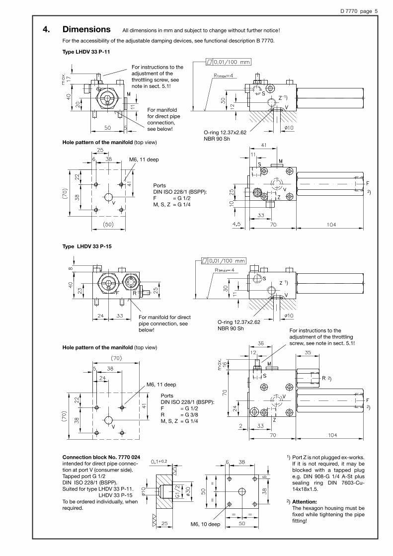
4. Dimensions All dimensions in mm and subject to change without further notice!
For the accessibility of the adjustable damping devices, see functional description B 7770.
Type LHDV 33 P-11
Hole pattern of the manifold (top view)
For manifold for directpipe connection, seebelow!
O-ring 12.37x2.62NBR 90 Sh
M6, 11 deep
M6, 10 deep
Ports DIN ISO 228/1 (BSPP):F = G 1/2R = G 3/8M, S, Z = G 1/4
For instructions to the adjustment of the throttlingscrew, see note in sect. 5.1!
For manifoldfor direct pipeconnection,see below!
Hole pattern of the manifold (top view)
O-ring 12.37x2.62NBR 90 Sh
1) Port Z is not plugged ex-works.If it is not required, it may beblocked with a tapped plug e.g. DIN 908-G 1/4 A-St plussealing ring DIN 7603-Cu-14x18x1.5.
2) Attention:The hexagon housing must befixed while tightening the pipefitting!
PortsDIN ISO 228/1 (BSPP):F = G 1/2M, S, Z = G 1/4
M6, 11 deep
For instructions to theadjustment of thethrottling screw, seenote in sect. 5.1!
Type LHDV 33 P-15
Connection block No. 7770 024intended for direct pipe connec-tion at port V (consumer side). Tapped port G 1/2 DIN ISO 228/1 (BSPP). Suited for type LHDV 33 P-11.
LHDV 33 P-15To be ordered individually, whenrequired.
1)
1)
2)
2)
2)
D 7770 page 6
1) Port Z is not plugged ex-works. If it is not required, it may be blocked with atapped plug e.g. DIN 908-G 1/4 A-St plussealing ring 14x18x1.5 DIN 7603-Cu
2) Attention:The hexagon housing must be fixed while tightening the pipe fitting!
3) Fitting for shock valve and corresponding holeare not apparent with type LHDV 33 H-11
For instruc-tions to theadjustmentof the throt-tling screw,see note insect. 5.1!
Centering pedestal and mounting
a/f 19max. torque130 Nm
O-ring 23.47x2.62NBR 90 Sh
O-ring 23.47x2.62 NBR 90 Sh
Ports Thread
V with version ..H M22x1.5 DIN 13with version H 1/2 G 1/2 A DIN ISO 228/1 (BSPP)
F G 1/2 DIN ISO 228/1 (BSPP)R G 3/8 DIN ISO 228/1 (BSPP)S, Z G 1/4 DIN ISO 228/1 (BSPP)M M8x1 DIN 13 (Type LHDV 33 H-15)M G 1/4 DIN ISO 228/1 (BSPP)
(Type LHDV 33 H-11)
Banjo bolt may bemounted from bothsides
For instructions to the adjustment of thethrottling screw, see note in sect. 5.1!
M8, 10 deep
M8, 10 deepboth sides
Ports conform. DIN ISO 228/1 (BSPP):F1, F2, V1, V2 = G 1/2
L, X = G 1/4Port L with...21L(WL)
Port X with ... 21 W (WL)(type LHDV 33-21WD withadditional hexagon housing)
Type LHDV 33 H-11LHDV 33 H-15
Type LHDV 33-21LHDV 33-21LLHDV 33-21WLHDV 33-21WDLHDV 33-21WL
Restrictor check valve, type BC 1-40 Ewith type LHDV 33-21WD
with typeLHDV 33-21WD
D 7770 page 7
1) AttentionThe hexagon housing must be fixed whiletightening the pipe fitting!
For instructions to the adjustment of the throttling screw, see note in sect.5.1!
M8, 10 deepboth sides
M8, 10 deep
Ports DIN ISO 228/1 (BSPP):F1, F2, V1, V2 = G 1/2L, X = G 1/4
Ports conforming DIN ISO 228/1 (BSPP): F1, F2, V1, V2 = G 1/2 T = G 3/4 L, X = G 1/4
For missing informationsee LHDV 33-25W!
1)
1)
Ports L with type ...25WD(N)L
Suction valve No. 7770 040 with type LHDV 33-25WDN -...
Suction valve No. 7770 060 with type LHDV 33-25WDNL -...
Restrictor check valve, type BC 1-40 Ewith type LHDV 33-25WD(N)-...
Port L withtype ...25L(WL)
1)
Port X with type ...25W(WL)
Type LHDV 33-25WDLHDV 33-25WDLLHDV 33-25WDNLHDV 33-25WDNL
Type LHDV 33-25LHDV 33-25LLHDV 33-25WLHDV 33-25WL
D 7770 page 8
The lock nut a/f 10 (Seal-Lock nut) needs to be loosened sufficiently prior to adjusting the throttling screw, otherwisethe vulcanized sealing gasket of the thread will be damaged!
Throttle screw(grub screw ISO 4026 M64h x 30-8.8-A2K)Caution: Do not unscrew the throttle screw above the maximum of 17 mm (as is illustrated in the adjacent figure)!Due to construction restrictions it cannot be anchored onthe inside of the equipment.
5. Appendix5.1 Dampening throttles
The dampening behavior may be extensively adapted within the adjusting range. This can be performed on site. It is recommended toinclude the following note and the schematic drawing into the operating manual or the operating instructions of the equipment.
5.2 Release pressure pin on the inflow sideThe required pressure at the pump pin to transfer the load against the load holding valve located down stream (direction V → F) can'tbe exactly predicted. It depends on the following parameter: Piston cross section area ratio Ain : Aout of the hydraulic cylinder, the internal operation area ratio of the load holding valve (release ratio acc. to sect. 3), the existing load pressure and theflow resistance |pF(R) of all additional throttling locations downstream back to the tank e.g. reflow pipe, directional valves (in the example A → R).The setting of an additional shock valve installed in the feeding pipe of the consumer has to be adjusted high enough, over the setting of the main pressure relieve valve, that it can overcome the highest release pressure (no load situation).Rough guiding figures suitable for a max. set pressure of 370 or 250 bar and max. flow dep. on valve coding, see sect. 2:pin max. , 130...170 bar at 370 bar set pressure
, 100...140 bar at 250 bar set pressurewith a piston cross section area ratio Ain : Aout of about 2...0.5 for the hydraulic cylinder. The return flow resistance can increase thesestandard guiding figures by about (1.1...3.5) x |pF(R) depending on the release ratio.A readjustment of the pressure limiting valve is possible on site when required.
Important note:The additional leakage port of the double valves acc. to sect. 2, page 3 (e.g. LHDV 33-21L -...) reduces the influence of the returnflow resistance back to the tank. An additional advantage is in the possibility that this leakage pipe, in the case of an emergency,can be shut-off with a hand pump.
Outflow side
Set pressure
Return flow pressure pR
Inflow side
Aout Ain
Pushing loadcomponent L
pin
Necessary pressure on the inflowside to move the hydraulic cylindertowards load direction
Load holding pressure pV
= sum of load pressure L/Aout,flow resistance |pV→ F of thevalve and return flow pressure pR
Direction ofmovement
Return flow Qout
Turning clockwise= throttle effect increases
Available adjustment
range of the throttle
4/3-way directional spool valve, preferablyaccording to the Load-Sensing-Principle.The inflow Qin in this switching positionP→B, controls the current reflow to thetank