TXV - Presentation TXV series pumps with Load Sensing control variable displacement piston pumps ► TXV series pumps are variable displacement with pressure-flow control – called Load Sensing. They self-regulate to give just the flow required for each movement. ► Specifically designed for the needs of the truck hydraulics market, TXV pumps are particularly well adapted for applications in: ▪ loader cranes, ▪ forestry cranes, ▪ refuse vehicles, ▪ salt spreaders, snow and ice equipment, ▪ construction equipment vehicles. ► Extremely compact in size to allow direct flange-mounting on vehicle engine or gearbox PTOs. ► TXV pumps are available in 11 models with maximum displacement from 40 to 150 cc/rev. Maximum pressure is up to 420 bar depending on model. ADVANTAGES
Transcript
T X V - P r e s e n t a t i o n
TXV series
pumps with Load Sensing control
v a r i a b l e d i s p l a c e m e n t p i s t o n p u m p s
► TXV series pumps are variable displacement with pressure-flow control – called Load Sensing. They self-regulate to give just the flow required for each movement.
► Specifically designed for the needs of the truck hydraulics market, TXV pumps are particularly well adapted for applications in: ▪ loader cranes, ▪ forestry cranes, ▪ refuse vehicles, ▪ salt spreaders, snow and ice equipment, ▪ construction equipment vehicles.
► Extremely compact in size to allow direct flange-mounting on vehicle engine or gearbox PTOs.
► TXV pumps are available in 11 models with maximum displacement from 40 to 150 cc/rev.
Maximum pressure is up to 420 bar depending on model.
A D VA N TA G E S
TXV
serie
s
Va r i a b l e d i s p l a c e m e n t - T X V
W h y u s e a v a r i a b l e d i s p l a c e m e n t p u m p ?
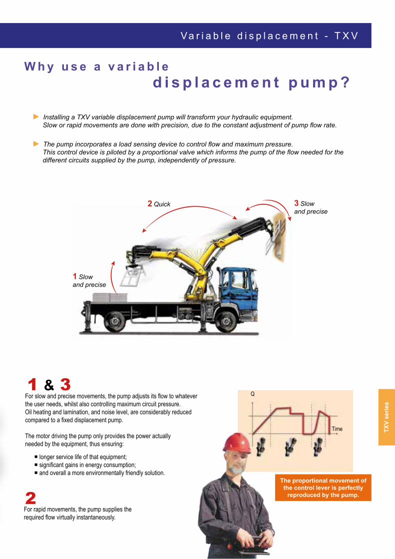
► Installing a TXV variable displacement pump will transform your hydraulic equipment. Slow or rapid movements are done with precision, due to the constant adjustment of pump flow rate.
► The pump incorporates a load sensing device to control flow and maximum pressure. This control device is piloted by a proportional valve which informs the pump of the flow needed for the different circuits supplied by the pump, independently of pressure.
Q
Time
For slow and precise movements, the pump adjusts its flow to whatever the user needs, whilst also controlling maximum circuit pressure. Oil heating and lamination, and noise level, are considerably reduced compared to a fixed displacement pump.
The motor driving the pump only provides the power actually needed by the equipment, thus ensuring:
For rapid movements, the pump supplies the required flow virtually instantaneously.
1 & 3
longer service life of that equipment; significant gains in energy consumption; and overall a more environmentally friendly solution.
2The proportional movement of the control lever is perfectly
reproduced by the pump.
2 Quick 3 Slowand precise
1 Slowand precise
T X V - H o w d o e s i t w o r k ?
Standby pressure setting Direct return to tank
(drain)
Pump pilot pressure line (LS)
Max. pump output pressure (PC)
► TXV variable displacement pumps are of axial piston design with 11 pistons, thus ensuring optimal regularity of flow and a low noise level. ► The displacement of the pump is proportional to the stroke of the pistons. Displacement – and thus flow - is varied by changing the angle α of the swashplate (Fig.1).
► To change displacement from maximum to zero (complete flow cancellation), the swashplate angle goes from α max (Fig. 1) to α min (=0) (Fig. 2).
► Setting the servo pump.
Figure 2 - zero displacement
Bleed screw
SwashplateBleed screw
Swashplate
α max
Figure 1 - Maximum displacement
TXV
serie
s
P r e s s u r e - f l o w r e g u l a t i o n : " L o a d S e n s i n g " - T X V
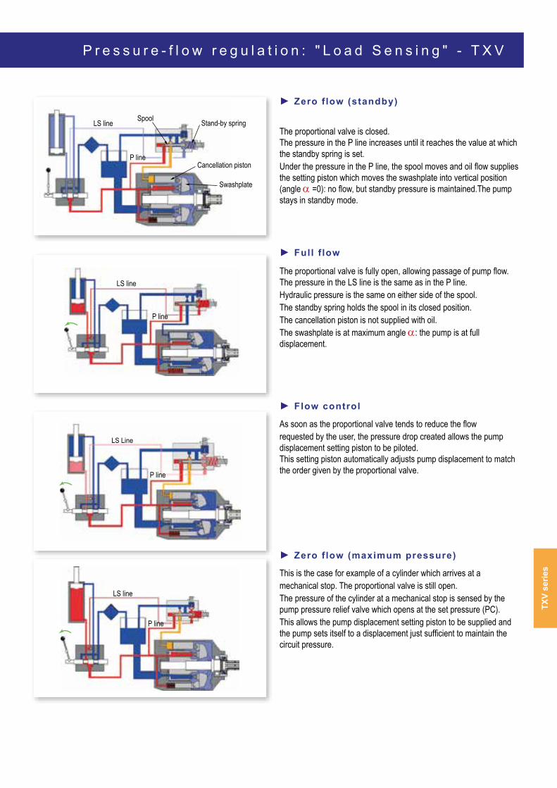
► Zero f low (standby)
The proportional valve is closed. The pressure in the P line increases until it reaches the value at which the standby spring is set. Under the pressure in the P line, the spool moves and oil flow supplies the setting piston which moves the swashplate into vertical position (angle α =0): no flow, but standby pressure is maintained.The pump stays in standby mode.
► Full f low The proportional valve is fully open, allowing passage of pump flow. The pressure in the LS line is the same as in the P line. Hydraulic pressure is the same on either side of the spool. The standby spring holds the spool in its closed position. The cancellation piston is not supplied with oil. The swashplate is at maximum angle α: the pump is at full displacement.
► Flow control
As soon as the proportional valve tends to reduce the flow requested by the user, the pressure drop created allows the pump displacement setting piston to be piloted. This setting piston automatically adjusts pump displacement to match the order given by the proportional valve.
► Zero f low (maximum pressure)
This is the case for example of a cylinder which arrives at a mechanical stop. The proportional valve is still open. The pressure of the cylinder at a mechanical stop is sensed by the pump pressure relief valve which opens at the set pressure (PC). This allows the pump displacement setting piston to be supplied and the pump sets itself to a displacement just sufficient to maintain the circuit pressure.
LS line Spool Stand-by spring
Cancellation piston
Swashplate
P line
LS line
P line
LS Line
P line
LS line
P line
T X V - C h a r a c t e r i s t i c s
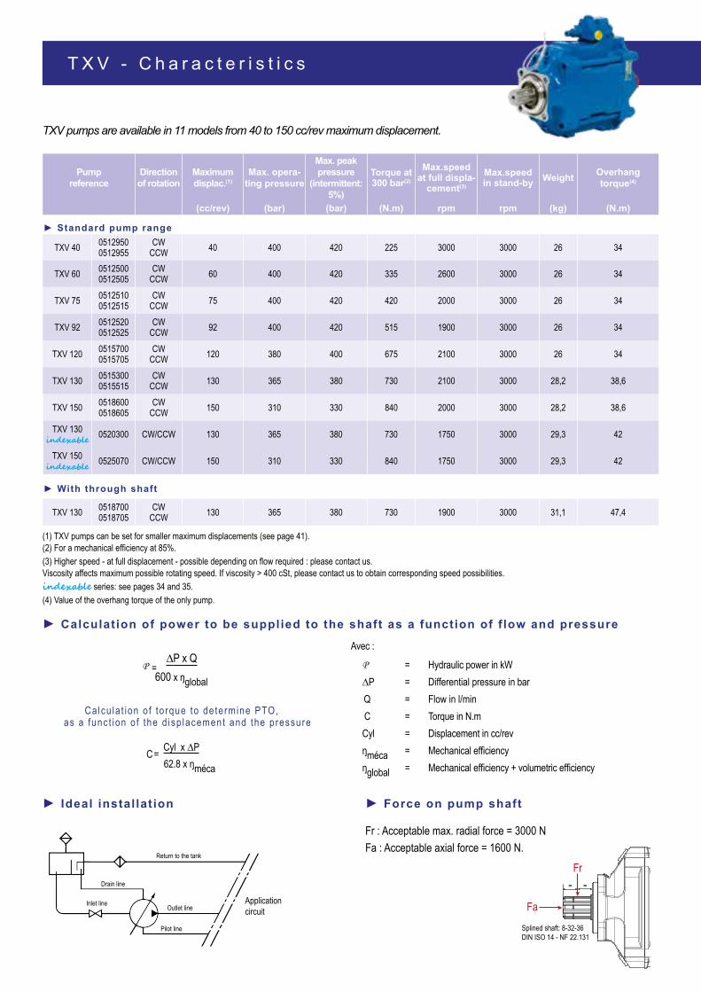
TXV pumps are available in 11 models from 40 to 150 cc/rev maximum displacement.
(1) TXV pumps can be set for smaller maximum displacements (see page 41). (2) For a mechanical efficiency at 85%.(3) Higher speed - at full displacement - possible depending on flow required : please contact us. Viscosity affects maximum possible rotating speed. If viscosity > 400 cSt, please contact us to obtain corresponding speed possibilities.indexable series: see pages 34 and 35.(4) Value of the overhang torque of the only pump.
► Ideal instal lat ion
► Calculation of power to be supplied to the shaft as a function of f low and pressure
Calcu la t ion o f to rque to de te rmine PTO, as a func t ion o f the d isp lacement and the p ressure
Splined shaft: 8-32-36DIN ISO 14 - NF 22.131
Fr
Fa
= =
► Force on pump shaft
Fr : Acceptable max. radial force = 3000 NFa : Acceptable axial force = 1600 N.
C= Cyl x ∆P62.8 x ŋméca
Avec :P = Hydraulic power in kW∆P = Differential pressure in barQ = Flow in l/minC = Torque in N.m Cyl = Displacement in cc/revŋméca = Mechanical efficiencyŋglobal = Mechanical efficiency + volumetric efficiency
Applicationcircuit
Return to the tank
Drain line
Inlet line Outlet line
Pilot line
P = ∆P x Q
600 x ŋglobal
TXV
serie
sAttention: the TXV indexables pumps are limited at 1750 rpm maximum.!
0
50
100
150
200
250
300
0 500 1000 1500 2000 2500 3000
TXV 150 �n��x����
TXV 150
TXV 130 �n��x����
TXV 130*
TXV 120
TXV 92
TXV 75
TXV 60
TXV 40
*TXV 130 with through shaftlimited at 1900 rpm.
Q (l/min)
N (rpm)
P e r f o r m a n c e - T X V
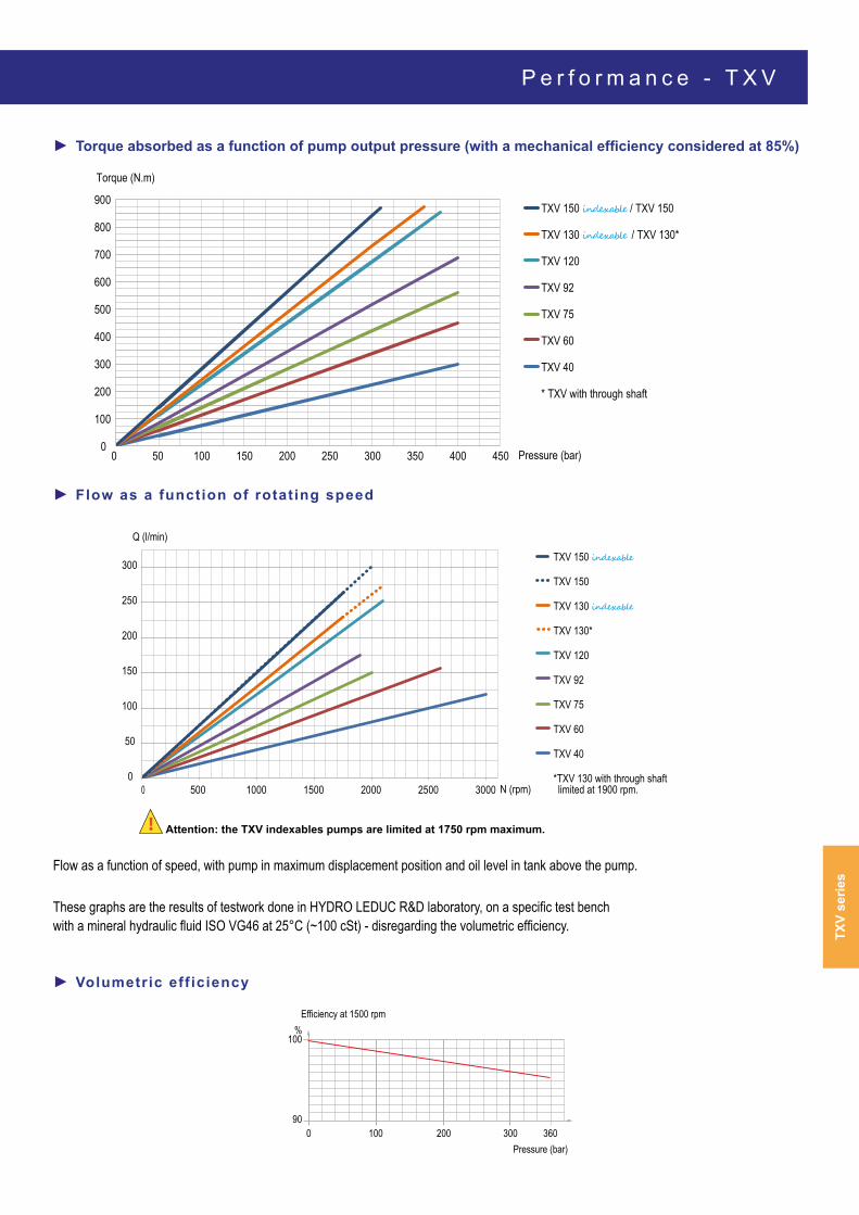
► Torque absorbed as a function of pump output pressure (with a mechanical efficiency considered at 85%)
► Flow as a function of rotating speed
► Volumetric eff iciency
Flow as a function of speed, with pump in maximum displacement position and oil level in tank above the pump.
These graphs are the results of testwork done in HYDRO LEDUC R&D laboratory, on a specific test bench with a mineral hydraulic fluid ISO VG46 at 25°C (~100 cSt) - disregarding the volumetric efficiency.
TXV 150 �n��x���� / TXV 150
TXV 130 �n��x���� / TXV 130*
TXV 120
TXV 92
TXV 75
TXV 60
TXV 40
* TXV with through shaft
Torque (N.m)
Pressure (bar)0
100
200
300
400
500
600
700
800
900
0 50 100 150 200 250 300 350 400 450
200100090
100%
300 360
Efficiency at 1500 rpm
Pressure (bar)
View from F View from F
CW CCW
A25
6.45
29
B2836
Outlet
Inlet
Connection for pressure gauge G1/4"
M10x1.5-6H (2x)Depth 15 mm toattach support device
A25
6.45
29
B28
36
Outlet
Inlet
T X V 4 0 t o 1 2 0 - D i m e n s i o n s
TXV 40 TO 12080
f7
194
955.1
331.1276
Splined shaft: 8-32-36DIN ISO 14 - NF 22.131(DIN 5462)
Drain G3/8’’connected to tank
Connectionfor pressure gauge G1/4’’
F 4080
4080
125
M12x1.75-6H
12.75 (4x)
LS G1/4"
stand-by pressuresetting
247.8
Max. pressure setting (PC)
► TXV connections
Pump reference
Outlet Inlet A B(Ø) (Ø) (mm) (mm)
TXV 40 to 92 G 3/4"G 1"1/2
15 19
TXV 120 G 1" 6 23.57
► Support device
In cases where it is necessary to use a support device (overhang torque) for the pump, this must be fixed to the same part which the pump is mounted on.
Dimensions in mm.
L
M
*Support device
Centre of gravity
Screw M10
* This support has to be designed to avoid strain on the pump flange.
► Mass and posit ion of centre of gravity
Pump type L (mm)
Weight (kg)
Overhang torque (N.m)
TXV 40 à 92 130 26 34TXV 120 130 26 34TXV 130 et TXV 150 128 28.2 38.6TXV 130 et TXV 150 indexable 128 29.3 42TXV 130 with through shaft 152.6 31.1 47.4TXV 130 constant torque 143 28.3 40
TXV
serie
s
D i m e n s i o n s - T X V 1 5 0
TXV 150
Inlet G1 1/2"
29.4 3732
5050
Connection forpressure gauge G1/4"
Outlet G1"
M10x1.5-6H (2x)Depth 15mm toattach support device
View from F View from F
CW CCW
219
321.1
Ø 80
f7
55.19
277
266
Splined shaft: 8-32-36DIN ISO 14 - NF 22.131(DIN 5462)
Standby pressure setting
Maximum pressure settingDrain G3/8"to be connected to tank
Connection forpressure gauge G1/4"
F
M12x1,75-6H
80
80127
40
40
LS G1/4"
F
Ø 12,75 (4x)
Dimensions in mm.
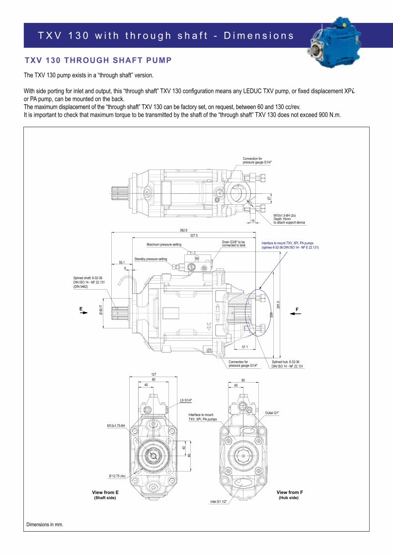
T X V 1 3 0 w i t h t h r o u g h s h a f t - D i m e n s i o n s
The TXV 130 pump exists in a “through shaft” version.
With side porting for inlet and output, this “through shaft” TXV 130 configuration means any LEDUC TXV pump, or fixed displacement XPi or PA pump, can be mounted on the back.The maximum displacement of the “through shaft” TXV 130 can be factory set, on request, between 60 and 130 cc/rev. It is important to check that maximum torque to be transmitted by the shaft of the “through shaft” TXV 130 does not exceed 900 N.m.
TXV 130 THROUGH SHAFT PUMP
228
382.6
Ø 80
f7
55.19
281.5
327.5
57.1
Splined shaft: 8-32-36DIN ISO 14 - NF 22.131(DIN 5462)
FE
Splined hub: 8-32-36DIN ISO 14 - NF 22.131
27
15M10x1.5-6H (2x)Depth 15mmto attach support device
Connection for pressure gauge G1/4"
M12x1.75-6H
80
80127
40
40
LS G1/4"
View from E(Shaft side)
8040
Inlet G1 1/2"
View from F(Hub side)
Outlet G1"Interface to mountTXV, XPi, PA pumps
Connection for pressure gauge G1/4"
Standby pressure setting
Maximum pressure setting Drain G3/8" to be connected to tank
Ø 12.75 (4x)
Interface to mount TXV, XPi, PA pumps(splines 8-32-36 DIN ISO 14 - NF E 22.131)
Dimensions in mm.
TXV
serie
s
D i m e n s i o n s - T X V 1 3 0 w i t h t h r o u g h s h a f t
Outlet G1"
Outlet G1"
Inlet G1 1/2"
Inlet G1 1/2"
CW CCW
View from F (see p.30)
TXV 130 THROUGH SHAFT PUMP
► Support device
The support device for the pump must be fixed to the same part which the pump is mounted on (see diagram below) and has to be designed to avoid strain on the pump flange.
Maximum torque transferable by the shaft of the pump driven by the PTO:
C = 900 N.m
That is, the sum of torque for both pumps must be < 900 N.m.
Please consult our Technical Department for advice regarding your installations.


![NORTA MIT PRESENTATION.pptx [Read-Only] · • Centrifugal pumps • Side channel pumps • Gear pumps • Screw pumps • Single screw pumps • Piston pumps • Vacuum pumps •](https://static.documents.pub/doc/80x56/5ec27ab9e3ef591d10504c3a/norta-mit-read-only-a-centrifugal-pumps-a-side-channel-pumps-a-gear-pumps.jpg)


