ARCHIWUM INSTYTUTU IN Ż YNIERII L Ą DOWEJ Nr 1 ARCHIVES OF INSTITUTE OF CIVIL ENGINEERING 2007 LOAD TEST OF HELICALLY CORRUGATED PIPE-ARCH UNDER RAILWAY Roman ŠAFÁŘ*, Jaromír ZOUHAR** *)Czech Technical University in Prague, Max Boegl & Josef Krysl **) ViaCon ČR, Olomouc Czech republic Abstract In the fall of 2005 the test of helically corrugated steel pipe-arch (1950 x 1320 mm) installed under railway was carried out. The objective of the test was to determine def- lections and stresses in the pipe wall in selected points. These values were measured during backfilling and under both symmetric and non-symmetric train loading. Recorded response of the pipe to both dead and live loads confirmed good correspondence be- tween theoretical calculations and actual measurements. Key words: Hel-Cor, corrugated steel pipe arch, railway load test 1. INTRODUCTION Hel-Cor is an acronym for “Helically Corrugated” shop-fabricated steel pipes. Circular pipes are manufactured of spiral-wound and corrugated at the same time straight coils. These pipes have spiral lockseams with a pitch dependent on the pipe diameter and have no bolts. The circular pipes can be then shaped on a hy- draulic press machine to a pipe-arch profile, later in the text referred to as “Hel- Cor pipe-arch” (Fig. 1). The first installations of Hel-Cor pipe-arches in the Czech republic as railway culverts come from 2004. In the fall of 2005 yet the largest-span Hel-Cor pipe-arch under railway was built (span 1,95 m, rise 1,32 m). The paper describes measurements performed in order to observe res- ponses of the pipe both to loads imposed on it during backfilling and live load on the finished culvert.
Transcript
A R C H I W U M I N S T Y T U T U I N Ż Y N I E R I I L Ą D O W E J Nr 1 ARCHIVES OF INSTITUTE OF CIVIL ENGINEERING 2007
LOAD TEST OF HELICALLY CORRUGATED PIPE-ARCH
UNDER RAILWAY
Roman ŠAFÁŘ*, Jaromír ZOUHAR** *)Czech Technical University in Prague, Max Boegl & Josef Krysl
**) ViaCon ČR, Olomouc Czech republic
Abstract
In the fall of 2005 the test of helically corrugated steel pipe-arch (1950 x 1320 mm) installed under railway was carried out. The objective of the test was to determine def-lections and stresses in the pipe wall in selected points. These values were measured during backfilling and under both symmetric and non-symmetric train loading. Recorded response of the pipe to both dead and live loads confirmed good correspondence be-tween theoretical calculations and actual measurements. Key words: Hel-Cor, corrugated steel pipe arch, railway load test
1. INTRODUCTION Hel-Cor is an acronym for “Helically Corrugated” shop-fabricated steel pipes. Circular pipes are manufactured of spiral-wound and corrugated at the same time straight coils. These pipes have spiral lockseams with a pitch dependent on the pipe diameter and have no bolts. The circular pipes can be then shaped on a hy-draulic press machine to a pipe-arch profile, later in the text referred to as “Hel-Cor pipe-arch” (Fig. 1).
The first installations of Hel-Cor pipe-arches in the Czech republic as railway culverts come from 2004. In the fall of 2005 yet the largest-span Hel-Cor pipe-arch under railway was built (span 1,95 m, rise 1,32 m).
The paper describes measurements performed in order to observe res-ponses of the pipe both to loads imposed on it during backfilling and live load on the finished culvert.
206 Roman Šafář, Jaromír Zouhar
Fig. 1. Hel-Cor pipe-arch fabrication
2. STRUCTURE DESCRIPTION The culvert is located under the single-track railway line Prostějov – Třebovice, 67,034 km far from Prostějov. There is a local flow in the culvert (afflux of Rychnovský potok).
The pipe is made of hot-dip galvanized steel DX51D(St02)Z600MA, con-forming to EN 10142, covered by 250 µm thick laminated polymer foil TREN-CHCOAT. It has a span of 1,95 m, rise of 1,32 m and is 11,00 m long. Thickness of the steel is 2,70 mm, corrugation has a pitch of 68 mm and a depth of 13 mm. In the vicinity of the culvert up to 1,0 m on either side and 0,5 m above the crown a well-graded sand-gravel mix with particles 0 – 45 mm compacted to 98% Standard Proctor density is used as a backfill. In order to minimize unequal loading of the pipe the backfilling work was performed simultaneously on both sides of the pipe, with maximum allowed difference of one layer, i.e. 0,15 m. Overfill (vertical distance between the crown of the pipe and top of sleepers) is 2,70 m high. The steel structure was delivered by ViaCon ČR, construction work was performed by Max Boegl & Josef Krýsl.
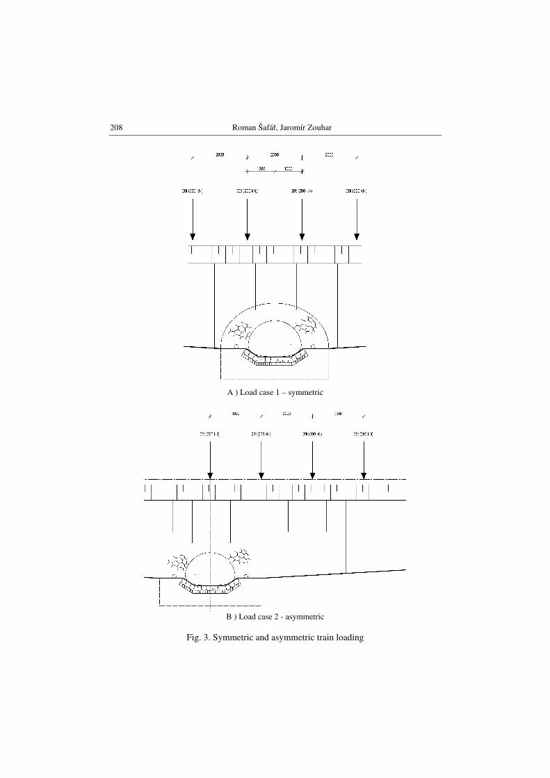
The rest of the trench is backfilled by the original excavated soil com-pacted to relative density ID = 0,90, in accordance with Czech standards for embankment construction. 3. MEASUREMENT Response of the culvert to backfilling loads was observed in four phases (Fig. 2). After the culvert was finished, static load test was performed using special 80-ton train with four axles spaced at 2 m, 20 tons per each axle placed in both symmetric and asymmetric position above the culvert centerline (Fig. 3). Since the Czech standard for load testing of culverts and bridges does not deal with
Load test of helically corrugated pipe-arch under railway
207
soil-steel culverts the testing program was arranged individually for this culvert. Schedule of the test is shown in Tab. 1.
Tab. 1. Load test schedule
Time (hours) Action Comment
H = 0:00 Beginning of measurement
0:00 – 0:30 0 Unloaded
0:30 – 0:45 Testing load drive-in
0:45 – 1:45 1 LC Loaded
1:45 – 2:00 Testing load drive-away
2:00 – 3:00 0 Unloaded
3:00 – 3:15 Testing load drive-in
3:15 – 4:15 2 LC Loaded
4:15 – 4:30 Testing load drive-away
4:30 – 5:30 0 Unloaded
5:30 – 6:00 Unmounting of gauges
a) phase 1 backfill up to the springline b) phase 2 backfill up to the crown
c) phase 3 backfill up to 1,35 m above the crown
d) phase 4 finished backfill up to the grade line
Fig. 2. Construction stages, in which recordings were taken
Roman Šafář, Jaromír Zouhar
208
A ) Load case 1 – symmetric
B ) Load case 2 - asymmetric
Fig. 3. Symmetric and asymmetric train loading
Load test of helically corrugated pipe-arch under railway
209
Strains and deflections were recorded during all four phases of the culvert backfilling and during train loading in three sections of the culvert: under the track centerline and in two sections 2 m distant on the left and right from the track centerline (Fig. 4).
Fig. 4. Location of gauges Deflections were measured using slide gauges with precision 0,1 mm.
Changes of the profile geometry were investigated as changes in length of four dashes A, B, C, D (Fig. 5); measured values are shown in Tab. 2 – 5.
Fig. 5. Geometry change measurement
Strains were recorded using resistance strain gauges C120 with precision 1.10^(-6) attached to the inner side of the culvert. There were two gauges in each measured location – one on inner crest of corrugation, one on outer crest of cor-rugation but also in the inner side of the pipe. Thus the gauges on outer crest of corrugation did not record maximum strains in the structure but the ones reduced about the plate thickness (about the plate thickness closer to the profile center-line). Stresses calculated from measured strains were calculated using Young’s modulus of 210 GPa. Results are shown in Tab. 2.
3,4
5,6
1,2
11,12
9,10
7,8
17,18
15,16
13,14
Tab. 2. Measured deformations of steel structure
Measuring No.
Stage Load case
Deformations [mm]
Cross Section I Cross Section II Cross Section III
Load test of helically corrugated pipe-arch under railway
211
Tab. 3. Calculated deformations of steel structure
Line Deformations [mm] Symmetric Asymmetric Load Load
A 8,180 5,270 B -3,890 -2,790 C -1,043 -1,615 D -1,056 0,039
Tab. 4. Measured normal stresses in steel structure – construction stages (green cells
show values measured on the air side of the corrugation)
Stage
Measured normal stresses – construction stages σσσσ [MPa]
Cross Section I
1 2 3 4 5 6
1 0,0 0,0 0,0 0,0 0,0 0,0
2 -5,7 6,5 -26,7 23,3 3,8 4,6
3 -40,1 28,6 -37,8 27,5 -16,0 18,3
4 -81,3 49,4 -36,3 21,6 -66,4 54,4
Cross Section II
7 8 9 10 11 12
1 0,0 0,0 0,0 0,0 0,0 0,0
2 -5,9 14,9 -29,8 23,5 14,1 4,8
3 -23,1 25,2 -36,8 25,8 -7,8 23,5
4 -56,7 41,0 -18,5 10,5 -18,3 33,4
Cross Section III
13 14 15 16 17 18
1 0,0 0,0 0,0 0,0 0,0 0,0
2 7,8 -1,9 -41,4 33,8 11,8 -5,9
3 -20,8 13,2 -58,0 40,5 -14,5 7,8
4 -39,9 18,1 -46,4 22,3 -38,9 19,1
Roman Šafář, Jaromír Zouhar
212
Tab. 5. Measured normal stresses in steel structure – load test (green cells show values measured on the air side of the corrugation)
Load
Case
Measured normal stresses – load test σσσσ [MPa]
Cross Section I
1 2 3 4 5 6
0 0,0 0,0 0,0 0,0 0,0 0,0
ZS1 -5,7 6,5 2,3 -2,5 4,8 -5,7
ZS1 -5,7 6,5 2,3 -2,5 4,8 -5,7
0 5,3 1,9 0,0 -4,4 -0,2 -3,4
0 5,3 1,9 0,0 -4,4 -0,2 -3,4
ZS2 -7,4 4,8 1,5 -3,4 3,6 -7,8
ZS2 -7,4 4,8 1,5 -3,4 3,6 -7,8
0 -5,5 2,5 1,3 -0,4 1,1 -2,3
0 -5,5 2,5 1,3 -0,4 1,1 -2,3
Cross Section II
7 8 9 10 11 12
0 0,0 0,0 0,0 0,0 0,0 0,0
ZS1 -18,9 -4,8 8,2 -0,8 -24,4 10,7
ZS1 -17,9 -3,2 4,0 -1,3 -20,6 5,9
0 -15,3 -0,4 1,9 -0,2 -19,7 2,1
0 -15,1 -2,3 -1,3 1,3 -17,6 1,5
ZS2 -15,5 -6,7 4,4 2,1 -26,7 6,3
ZS2 -15,5 -6,9 4,2 -1,1 -22,7 6,5
0 -11,3 -2,1 1,5 6,9 -21,6 3,2
0 -13,9 -0,4 0,8 4,4 -21,0 1,9
Cross Section III
13 14 15 16 17 18
0 0,0 0,0 0,0 0,0 0,0 0,0
ZS1 -24,8 11,8 0,8 -1,7 -9,9 2,9
ZS1 -24,8 11,8 0,8 -1,7 -9,9 2,9
0 -18,5 -0,8 1,5 -0,4 -2,5 1,1
0 -18,5 -0,8 1,5 -0,4 -2,5 1,1
ZS2 -22,9 -3,6 3,8 -1,7 -9,9 4,8
ZS2 -22,9 -3,6 3,8 -1,7 -9,9 4,8
0 -18,5 -1,5 -0,2 -2,7 -3,6 0,4
0 -18,5 -1,5 -0,2 -2,7 -3,6 0,4
Load test of helically corrugated pipe-arch under railway
213
4. CONCLUSIONS Although dimensions of the structure are not too large and so measured values of stresses and deformations were quite low, measurements carried out both during construction and during load test of the finished structure proved adequate cor-respondence between theoretical calculations and practical measurements. The structures behave according to the theoretical assumptions and it is possible to use them for civil engineering structures of roads and railways. Acknowledgement
Load test and measurements of the structure were financed by the same amount from three sources: supplier of the steel structure ViaCon ČR, ltd., and research projects No. 103/05/2003 (supported by the Grant Agency of the Czech Repub-lic) and No. 1M6840770001 (supported by the Ministry of Education in scope of activity of the research centre of CIDEAS).
BADANIA NAD SPIRALNIE KARBOWANYMI RURAMI Z BLACHY FALISTEJ
O KSZTAŁCIE ŁUKOWO-KOŁOWYM POD OBCIĄŻENIAMI KOLEJOWYMI
Streszczenie Jesienią 2005 roku zostały przeprowadzone badania nad spiralnie karbowanymi rurami z blachy falistej o kształcie kroplistym zastosowanymi pod drogą kolejową. Celem badań było określenie odkształceń i naprężeń w ściance rury falistej w wybranych punktach. Wartości te zostały zmierzone w trakcie zasypywania i pod symetrycznie i niesyme-trycznie obciążeniem pociągiem. Zarejestrowana reakcja na obciążenia stałe i zmienne potwierdziła dobrą zależność pomiędzy teoretycznymi założeniami i rzeczywistymi pomiarami. Słowa klucze: Hel-cor, rura z blach falistych o kształcie kroplistym, badania pod obcią-żeniem kolejowym