58
Loads Dead loads Imposed loads floor roof Determining load per m and m2 Wind

Loads
Dead loadsImposed loads floor roofDeterminingloadpermandm2Wind

Structurestransmitloadsfromoneplacetoanother
Wheredoloadscomefrom
Deadloads-permanentandstationary
StructureitselfPlantandequipment
Someroughfigures(notethatvaluesaresubjecttovariationdependingonspecifcmaterialtype)Alsonotevaluesareforcesperunitvolumenotmassperunitvolume.
UnitWeightsofbaiscconstructionmaterials kN/m3Aluminium 24Brick 22Concrete 24Steel 70Timber 6

Precastconcretebeamlength
1.Calculateweightofbeamperunitlength.2.Calculatetotalweightofbeaminitis10.5m.
Firstcrosssectionalareaofbeam=
(0.6x0.25)-(0.4x0.15)=0.09m2
Fromtableunitweightofconcrete=24kN/m3
Weightperunitlength=0.09x24=2.16kN/m
Totalweight=2.16x10.5=22.68kN

Oftenwearedealingwithsheetmaterialsorweknowalayerthicknessoffloororroofbuildup.
Figureshereareperunitarea
Againwhenusingthesetypeofchartssomecareisneededtoensureyouhavethecorrectfigure,orthatitcorrespondswithyourdesign.
Unitweightofbasicsheetmaterials kN/m2Asphalt(19mm) 0.45Aluminiumroofsheeting 0.04Glass(singleglazing) 0.1Plasterboardandskim 0.15Raftersbattensroofingfelt 0.14Sand/cementscreed(25mm) 0.6Slates 0.6Timberfloorboards 0.15Plasteronwallface 0.3

CalculatethedeadloadinkN/m2ofthefollowingfloorbuildup:
Timberfloorboards40mmsand/cementscreed125mmreinforcedconcreteslab
timberfloorboards =0.15screed =0.6x40/25=0.96concreteslab =0.125x24=3.00
dead load /m2 =4.11kN/m2

ifwearedealingwithawallactingonabeamweareinterestedinloadperlinearunitofthebeam
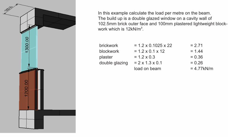
Inthisexamplecalculatetheloadpermetreonthebeam.Thebuildupisadoubleglazedwindowonacavitywallof102.5mmbrickouterfaceand100mmplasteredlightweightblock-workwhichis12kN/m3.
brickwork =1.2x0.1025x22 =2.71blockwork =1.2x0.1x12 =1.44plaster =1.2x0.3 =0.36doubleglazing =2x1.3x0.1 =0.26
loadonbeam =4.77kN/m

Imposedloads-orliveloads,movableloadsthatactonthestructurewhenitisinuse.
People,furniture,cars,computersandmachineryareallimposedloads.
NormallyweconsiderimposedloadsasfloorandroofloadsTypicalfloorloads kN/m2Artgalleries 4.0Bankinghalls 3.0bars 5.0Carparks 2.5Classrooms 3.0Churches 3.0Computerlabs 3.5Dancehalls 5.0Factoryworkshop 5.0Foundaries 20.0Hotelbedrooms 2.0Offices(general) 2.5Offices(filing) 5.0Privatehouses 1.5Shops 4.0Theatres(fixedseats) 4.0

Ifabarshouldbedesignedwithliveloadof5.0kN/m2andifanaveragepersonis80kghowmanypeopleareexpectedtobestandinginonesquaremetreoffloor?
Forceexertedbyoneperson =80x9.81 =785NNumberofpeopleperm2 =5000/785 =6.4people/m2
equivalentlyifyourhouseisdesignedwith1.5kN/m2andthetotalareawas22m2howmanypeoplecouldyouinvitetoaparty?
Forceexertedbyoneperson =785NNumberofpeopleperm2 =1500/785 =1.9people/m2Totalnumberofpeopleatparty =1.9x22 =42andabit.
certaintypesofdancingcancausedynamiceffectsthatincreasetheeffectofload.

Calculatingimposedroofloads.
Whatyouneedtoknow:
1.Isaccesstotheroofprovided?(aloadofadjacentfloorareaisrequired)2.Predominantloadissnow.• whichisdependanton• geographicallocation• heightabovesealevel• shapeofroof• windthatredistributessnowintodrifts

EstimatinggroundsnowloadsinCanada.InfofromCanadianCryosphericInformationNetworkFindworstcasedepthandmultiplybydensity(kg/m3)and9.81
TablesinNationalBuildingCodeprovidefurtherdetails

InUKsnowloadvariesfrom0.3kN/m2onsouthcoastto3.0kN/m2inScotland
CalculatingasnowloadinCanada.NationalBuildingCodePart44.1.7.
S=Ss (CbxCwxCsxCa)+Sr
Snowloadperm2
groundsnowloadinkPa(kN/m2)
roofsnowloadfactor=0.8???
windexposurefactor
slopefactor
accumulationfactor
associatedrainload
NationalBuildingCodeofCanadaappendixcfortablesofclimaticinformation

windexposurefactor
is1.0butcanbereducedto0.75orinexposedareasnorthoftreelineto0.5 if buildingisanexposedlocationandexposedonallsides noobstructionsaroundbuilding noobstructionsonroofsuchasparapet snowcannotdriftontorooffromadjacentsurfaces
slopefactorbasedonroofangleaandsurfacetype. is1.0ifa<=30⁰ is(70⁰ -a)/40⁰whena>30⁰ is0ifa>70⁰
ifroofisaslipperysurface(wheresnowandiceslideoff)
slopefactor is1.0ifa<=15⁰ is(60⁰ -a)/40⁰whena>15⁰ is0ifa>60⁰
NationalBuildingCodeofCanadaappendixcfortablesofclimaticinformation

accumulationfactor
is1.0 exceptwhen forlargeflatroofswhen 1.2x[1-(30/l)2]butnotlessthan1.0forroofswithwindfactor=1.0 1.6x[1-(120/l)2]butnotlessthan1.0forroofswithwindfactor=0.75or0.5
w=smallerplandimension L=largerplandimension and lis2xw-(w2/L)inmetres
canbeassignedothervalueswhen: roofshapesarearched,curvedordomes snowloadsinvalleys snowdriftsfromanotherroof projectionsonadjacentroofs snowslidingordrainagefromadjacentroofs

Theresmore:
inrealityfullandpartialloadinghastobeconsidered
Inadditiontotheloadcalculationaboveroofsofslopelessthan15⁰andarchedorcurvedroofsmustbedesignedwithaccumulationfactor1.0ononeportionwhilehalfthatloadisappliedtotheremainder.

Calculatesnowloadonthisroofstructure
Whatisthesnowloadpermetrelengthoftruss?
Whatisthetotalsnowloadononerooftruss?
Whatistheloadpermetreonthesupportingwall?Assumethatloadsfromtrussesareevenlydistributed

CalculatesnowloadforHalifaxS
groundsnowHalifax=1.7
snowloadfactor=0.8
windexposurefactor=1.0
slopefactor=(70-40)/40=0.75
accumulationfactor=1.0
rainloadHalifax=0.5
S=1.7x(0.8x1x0.75x1)+0.5
S=1.52kN/m2
Snowloadperm2
groundsnowloadinkPa(kN/m2)
roofsnowloadfactor=0.8???
windexposurefactor
slopefactor
accumulationfactor
associatedrainload
S=Ss (CbxCwxCsxCa)+Sr

Trussesareat0.6mcentres
Sosnowloadpermetrelengthoftrussis:
0.6x1.52=0.9kN/m
Noteloadisverticalso1mdimen-sionismeasuredhorzontally
For7mtrussloadis
7x0.9=6.4kN

Loadpermonwall=1.52x3.5=5.32kN/m
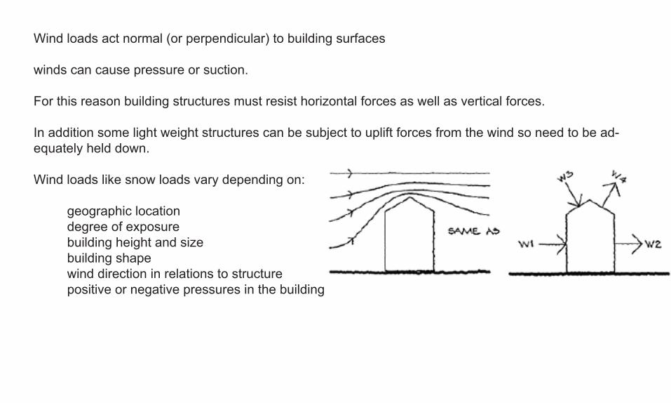
Windloadsactnormal(orperpendicular)tobuildingsurfaces
windscancausepressureorsuction.
Forthisreasonbuildingstructuresmustresisthorizontalforcesaswellasverticalforces.
Inadditionsomelightweightstructurescanbesubjecttoupliftforcesfromthewindsoneedtobead-equatelyhelddown.
Windloadslikesnowloadsvarydependingon:
geographiclocation degreeofexposure buildingheightandsize buildingshape winddirectioninrelationstostructure positiveornegativepressuresinthebuilding

Fastermovingaircreateslowerpressure(bernoullieffect)asinplanewings.
Thesameprinciplecausesforcestoactonbuildingsurfaces.
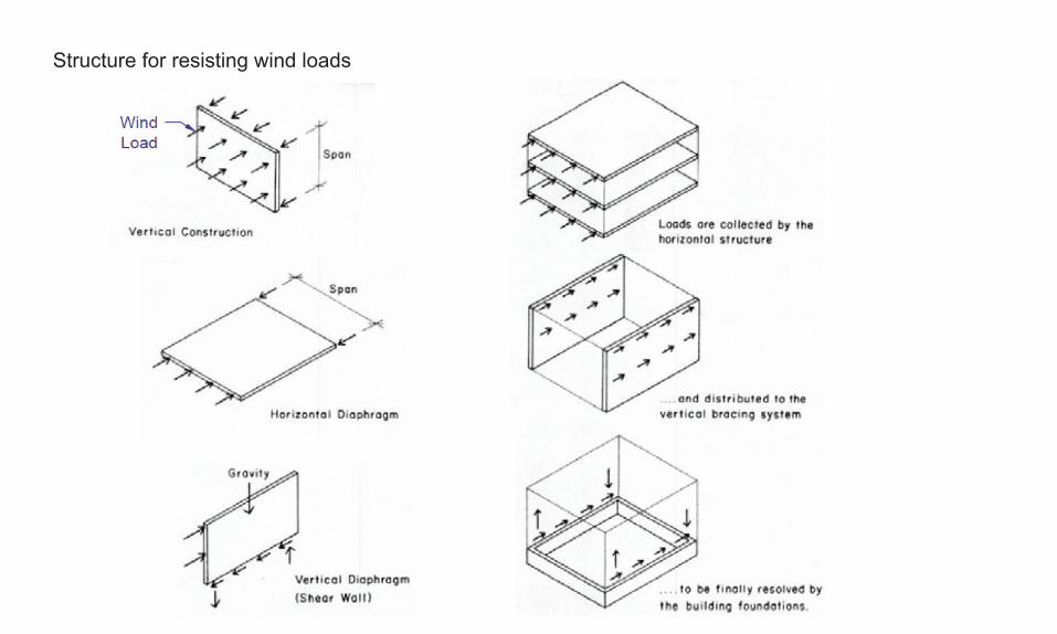
Structureforresistingwindloads


Theseprinciplesshouldbewellunderstoodbynowifnot
Lookat: FrancisChing.BuildingConstructionIllustrated
EdwardAllen.Architect’sStudioCompanion

Forstructuraldesignitisoftennecessarytoconsiderseveralloadcasesduetothewindblowingfromdifferentdirections.
DesigningabuildinginHalifaxcalculatingwindloads.NationalBuildingCodeofCanadaPart44.1.8.
p=qxCexCgxCp
externalpressureactingstaticallyandnormaltosurface
referencevelocitypressure
exposurefactor
gusteffectfactor
externalpressurecoefficient
NationalBuildingCodeofCanadaappendixcfortablesofclimaticinformation
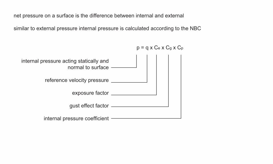
netpressureonasurfaceisthedifferencebetweeninternalandexternal
similartoexternalpressureinternalpressureiscalculatedaccordingtotheNBC
p=qxCexCgxCp
internalpressureactingstaticallyandnormaltosurface
referencevelocitypressure
exposurefactor
gusteffectfactor
internalpressurecoefficient

referenceveloctypressurethreeareshownintable1in10,1in30,1in100
theseareprobabilitiesofpressureoccuring
so1in10isusedforcladdingandstucturaldesignforvibrationanddeflection
1in30forstructuralstrength
post-disasterbuldingsusethe1in100pressurevalues.
exposurefactor
exposureincreasewithheightheightm exposurefactor>0and<=6 0.9>6and<=12 1.0>12and<=20 1.1>20and<=30 1.2>30and<=44 1.3>44and<=64 1.4andsoonmoreheightsgiveninnbc

gustfactor
1.0or2.0forinternalpressurestobefoundsomewhereinthe500pagesofappendixA!! we’lluse1.0fornow.
2.0forthebuildingasawholeandmainstructuralmembers
2.5forsmallelements
externalandinternalpressurecoefficients
againappendixAwe’lluse1.0fornow.


Forcesduetowindonsimplebuilding
externalpressurep=qxCexCgxCp
1in30yearPressureHalifax=0.52kPa(kN/m2)
Wallsbelow6msoexposurefactoris0.9
Gustfactor=2.0externaland1.0internal
Pressurecoefficient=1.0
externalp=0.52x0.9x2.0x1.0=0.936kN/m2
internalp=0.52x0.9x1.0x1.0=0.468kN/m2
so0.936-0.468=0.468kN/m2actingnormaltoverticalsurfaceswindward
and0.936+0.468=1.4kN/m2leeward

Forcesduetowindonsimplebuilding
externalpressurep=qxCexCgxCp
1in30yearPressureHalifax=0.52kPa(kN/m2)
Roofabove6msoexposurefactoris1.0
Gustfactor=2.0externaland1.0internal
Pressurecoefficient=1.0
externalp=0.52x1.0x2.0x1.0=1.04kN/m2
internalp=0.52x1.0x1.0x1.0=0.52kN/m2
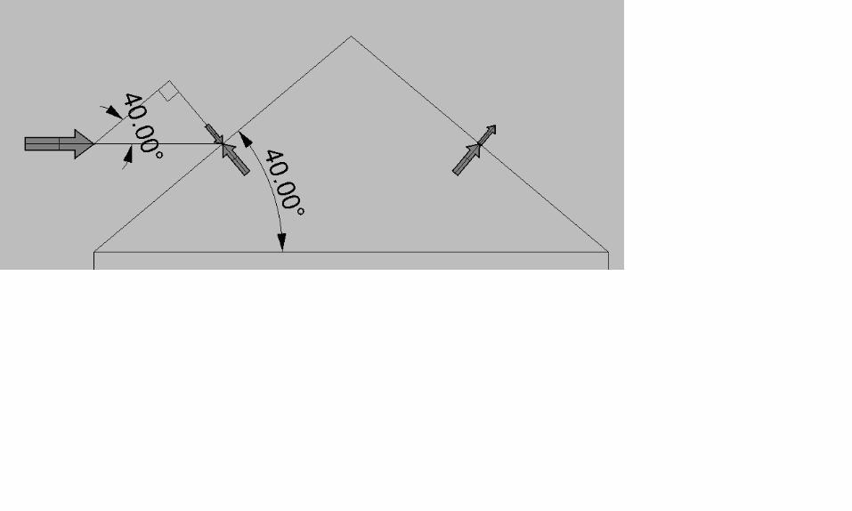
1.04kN/m2actingnormaltoverticalsurfacesatrooflevel
normaltoroof1.04xSin(40)=0.67 windward=0.67-0.52=0.15kN/m2 leeward=0.67+0.52=1.19(suction)

Nextup:Acoupleofotherloadtypes(toknowabout)UniformandpointloadsSafetyfactorsCalculatingloadonbeamsLoadpaths
PinJointedstructures

A couple of other load types (to know about)Uniform and point loadsSafety factors Calculating load on beamsLoad paths

Hydrostatic pressure loads from soils and liquids
Increases linearly with depth.

Application of safety factors to loads
Loads discussed are realistic estimates of loads or characteristic loads
when checking ultimate strength characteristic loads are increased by multiplying by a safety factor.
The result is the design load.Safety factors
load combination dead imposed winddead and imposed 1.4 or 1.0 1.6 -dead and wind 1.4 or 1.0 - 1.4dead, imposed and wind 1.2 1.2 1.2

For example
to obtain the maximum compressive design in the support at Btwo load combinations should be checked and the larger value used
1.4 x dead + 1.6 imposed
or
1.2 x dead + 1.2 x imposed + 1.2 wind
to obtain maximum tensile design load in the support at A
we need to minimise the effect of the dead and imposed loads by using
1.0 x dead + 1.4 x wind
A B
wind
imposed roof
imposed floor
dead load

Point load (kN)
Uniformly distributed load (kN/m)

Calculating loads on beams
Example
Building type - officeFloor construction = 4.11kN/m2Perimeter wall construction = 4.77kN/m2self weight of beams = 0.6 kN/m
safety factors are 1.4 for dead load and 1.6 for live load to find design load
design load kN/m2floor 1.4 x 4.11 5.75wall 1.4 x 4.77 6.68beams 1.4 x 0.6 0.84imposed 1.6 x 2.5 4.00
total design floor load = 5.75 + 4.00 = 9.75kN/m2
B6

Beam B1 (8m span)supports a total width of 6m
load from floor = 9.75 x 6 = 58.50kN/mself weight of beam = 0.84 kN/m
design UDL = 59.34 kN/m
symmetry indicates reactions will be equal
reaction = (59.34 x 8) / 2 = 237.4 kN
beam B2 is the same as B1
B6

Beam B3 suports a 3m width of floor plus the perimeter wall
Load from floor = 3 x 9.75 = 29.25 kN/mload from wall = 6.68kN/mself weight of beam = 0.86kN/m
total design UDL = 36.79kN/m
symmetry indicates reactions will be equal
reaction = (36.9 x 8) /2 = 147.6kN

Beam B4 has same UDL as B1 and B2 but span is 6m
B6

Beam B6
Supports perimeter wall and a point load from the reaction of B2.
Load from wall = 6.68kN/mself weight of beam = 0.86kN/m
design UDL = 7.54kN/m
design point load = 237.4kN
Reaction from symmetry
= ((7.54 x 12) + 237.4) / 2 = 163.9kN
B6

Now work out reactions for B5
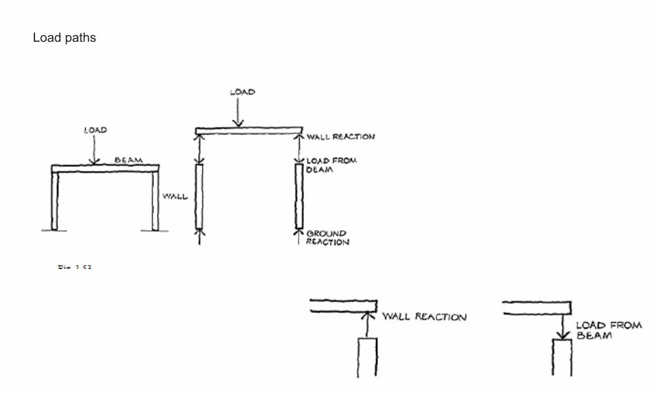
Load paths


Working through load path for a simple sign.


