Localization of Wearable Users Using Invisible Retro-reflective Markers and an IR Camera Yusuke Nakazato, Masayuki Kanbara and Naokazu Yokoya Graduate School of Information Science, Nara Institute of Science and Technology, 8916–5 Takayama, Ikoma, Nara, 630–0192, Japan ABSTRACT This paper describes a localization method for wearable computer users. To realize applications of wearable computers like a navigation system, the position of a user is required for location-based services. Many localiza- tion methods in indoor environments have been proposed. One of the methods estimates user’s position using IR beacons or visual markers. However, these methods have same problems concerning power supply and/or undesirable visual effects. In order to avoid the problems, we propose a new localization method which is based on using an IR camera and invisible markers consisting of translucent retro-reflectors. In the proposed method, to extract the regions of the markers from the captured images stably, the camera captures the reflection of IR LEDs which are flashed on and off synchronously. Keywords: Retro-reflective Marker, IR Camera, Localization, Wearable Computer 1. INTRODUCTION Since computers have made remarkable progress in resent years, a wearable computer can be realized 1 . At the same time, the augmented reality (AR) technique which merges the real and virtual worlds has received a great deal of attention as a new method for displaying location-based information in the real world 2–4 . Therefore, AR systems using wearable computers like navigation systems 5–8 are proposed. To realize an AR system using wearable computer, the exact position and orientation of a user are required. Especially in indoor environments, since a GPS can not be used, many localization methods have been proposed 9, 10 . One of the methods estimates the user’s position using infrared markers 11, 12 . The methods specify the user’s position using the position IDs received from IrDA markers which compose positioning infrastructures. Tenmoku, et al 11 have estimated user’s position using infrared markers and pedometer, and the orientation of the user by gyro sensor. Maeda, et al 12 developed a hybrid tracking system that estimates more exactly the position and orientation of the user by combining a gyro sensor with a stereo camera which captured infrared markers. Another method estimated the user’s position by recognizing the visual markers which are pasted up on the ceilings or walls 13, 14 . Baratoff, et al 13 used ARToolKit 15 square markers, as shown Figure 1(a) . Naimark, et al 14 developed a system that estimates more stably the position and orientation of the user by combining an accelerometer with a camera which captured circular markers as shown Figure 1(b) . However, these methods have some problems concerning power supply of positioning infrastructure and/or undesirable visual effects. In order not to impair the scenery, we propose a new localization method using invisible markers that consist of translucent retro-reflectors. In the proposed method, translucent retro-reflective markers, which are invisible and do not need power supply, are captured by an IR camera. In order to avoid the influence of infrared other than the reflection from retro-reflective markers, infrared LEDs are flashed on and off continuously. Thus, the images containing the markers are captured synchronized with it. The regions of the markers are robustly extracted from the difference between images as LED on and off. Herewith, the position of a user can be estimated without power supply of infrastructures and undesirable visual effects in the real scene. This paper is structured as follows. Section 2 describes a localization system using invisible markers and IR camera. In Section 3, experimental results with a prototype system are described. Finally, Section 4 describes conclusion and future work. Further author information: (Send correspondence to Y. N.) Y. N.: E-mail: [email protected], Telephone: +81 743 72 5296 M. K.: E-mail: [email protected], Telephone: +81 743 72 5292 N. Y.: E-mail: [email protected], Telephone: +81 743 72 5290
Transcript
Localization of Wearable UsersUsing Invisible Retro-reflective Markers and an IR Camera
Yusuke Nakazato, Masayuki Kanbara and Naokazu Yokoya
Graduate School of Information Science, Nara Institute of Science and Technology,8916–5 Takayama, Ikoma, Nara, 630–0192, Japan
ABSTRACTThis paper describes a localization method for wearable computer users. To realize applications of wearablecomputers like a navigation system, the position of a user is required for location-based services. Many localiza-tion methods in indoor environments have been proposed. One of the methods estimates user’s position usingIR beacons or visual markers. However, these methods have same problems concerning power supply and/orundesirable visual effects. In order to avoid the problems, we propose a new localization method which is basedon using an IR camera and invisible markers consisting of translucent retro-reflectors. In the proposed method,to extract the regions of the markers from the captured images stably, the camera captures the reflection of IRLEDs which are flashed on and off synchronously.
Keywords: Retro-reflective Marker, IR Camera, Localization, Wearable Computer
1. INTRODUCTIONSince computers have made remarkable progress in resent years, a wearable computer can be realized1 . At thesame time, the augmented reality (AR) technique which merges the real and virtual worlds has received a greatdeal of attention as a new method for displaying location-based information in the real world2–4 . Therefore,AR systems using wearable computers like navigation systems5–8 are proposed. To realize an AR system usingwearable computer, the exact position and orientation of a user are required. Especially in indoor environments,since a GPS can not be used, many localization methods have been proposed9, 10 . One of the methods estimatesthe user’s position using infrared markers11, 12 . The methods specify the user’s position using the position IDsreceived from IrDA markers which compose positioning infrastructures. Tenmoku, et al11 have estimated user’sposition using infrared markers and pedometer, and the orientation of the user by gyro sensor. Maeda, et al12
developed a hybrid tracking system that estimates more exactly the position and orientation of the user bycombining a gyro sensor with a stereo camera which captured infrared markers. Another method estimated theuser’s position by recognizing the visual markers which are pasted up on the ceilings or walls13, 14 . Baratoff,et al13 used ARToolKit15 square markers, as shown Figure 1(a) . Naimark, et al14 developed a system thatestimates more stably the position and orientation of the user by combining an accelerometer with a camerawhich captured circular markers as shown Figure 1(b) . However, these methods have some problems concerningpower supply of positioning infrastructure and/or undesirable visual effects.
In order not to impair the scenery, we propose a new localization method using invisible markers that consistof translucent retro-reflectors. In the proposed method, translucent retro-reflective markers, which are invisibleand do not need power supply, are captured by an IR camera. In order to avoid the influence of infrared other thanthe reflection from retro-reflective markers, infrared LEDs are flashed on and off continuously. Thus, the imagescontaining the markers are captured synchronized with it. The regions of the markers are robustly extractedfrom the difference between images as LED on and off. Herewith, the position of a user can be estimated withoutpower supply of infrastructures and undesirable visual effects in the real scene.
This paper is structured as follows. Section 2 describes a localization system using invisible markers and IRcamera. In Section 3, experimental results with a prototype system are described. Finally, Section 4 describesconclusion and future work.
(a) Augmented reality system using squaremarkers (Baratoff, et al13).
(b) Localization system using camera and ac-celerometer (Naimark, et al14).
Figure 1. Localization methods using visual markers.
2. USER LOCALIZATION USING INVISIBLE MARKERS
In this section, our proposed localization system is described in detail. In Section 2.1, the invisible markers aredescribed. Section 2.2 discusses marker patterns, and finally Section 2.3 explains a method for estimation ofposition and orientation.
2.1. Invisible Markers
The markers are set up on the ceilings or walls in indoor environments as infrastructures. When visual markersare set up on the ceilings, the markers impair the scenery as shown in Figure 2(a). Figure 2(b) shows the scenewhere invisible markers consisting of translucent retro-reflectors are set up. Since the markers are translucent, itis difficult for a user to observe the markers. However, when the image is captured with a flash, the markers canbe clearly observed as shown in Figure 2(c). Because the retro-reflector reflects a light toward a light source, itsreflection can be captured clearly by the camera which is located near the flashing light.
(a) Visual markers. (b) Invisible markers. (c) Invisible markers with a flash.
Figure 2. Markers of positioning infrastructures.
Figure 3. Instances of markers (N = 4) (the black part illustrates a retro-reflector).
2.2. Pattern of markers
Figure 3 illustrates instances of marker patterns. In this figure, the black part illustrates the retro-reflector, andthe marker has a square frame. To generate a marker pattern, the inside of the frame contains evenly spacedN × N grid points, and small squares are allocated on the grids. To determine the direction of the markeruniquely, one small square is always allocated to one of four corners of N ×N grids, and other three corners areblank. Therefore, the total number of IDs associated the patterns is 2N2−4.
2.3. Estimation of position and orientation
Figure 4 illustrates the overview of the proposed localization system. Invisible markers consisting of translucentretro-reflectors are set up on the ceilings or walls. The user equips the head with an infrared camera shown inFigure 5 upward for capturing images. The camera captures the reflection of the infrared LEDs that are attachedto it. The reflection of retro-reflector can be captured clearly by the infrared camera.
Translucent Retro-reflective Marker
IR LEDs and IR camera
RS-232C
Wearable Computer (MP-XP7310 [Victor])
Video Capture Unit (NV-UT200 [NOVAC])
ReflectionInfrared Light
Figure 4. Overview of localization system.
Infrared Camera
Infrared LED
72mm
47mm
Figure 5. Infrared camera and infrared LEDs.
Capturing image
Capturing image
IR-LED switch on
IR-LED switch off
Image subtraction
Marker recognition &Position estimation
Figure 6. Flow diagram of capturing markers.
However, the camera also captures lights other than the infrared LEDs; for examples, fluorescent and sunlight. To avoid such a problem, infrared LEDs are flashed on and off synchronously under control of a wearablecomputer as shown in Figure 6. In the image without infrared light from the infrared LEDs, invisible markersare not captured. On the other hand, in the image with infrared light from the infrared LEDs, these are clearlycaptured. By calculating the difference between the images with and without infrared light from the LEDs,the influence of infrared other than the reflection from retro-reflective markers can be eliminated. From thesubtraction images, the regions of the markers are extracted, and IDs associated with the markers are recognized.To extract the regions of markers, ARToolKit15 can be used. In addition to identifying the received marker,it is possible to estimate the relative position and orientation of camera with respect to the marker coordinatesystem from the four vertices of a square marker of known size using a standard computer vision technique.
3. EXPERIMENTS
We have carried out experiments with the proposed localization system. View angle of the infrared camerashown in Figure 5 is 92.6◦, and six infrared LEDs are attached around the camera. We made a circuit whichcontrols the LEDs using RS-232C serial communication with a PC. The used PC is a mobile computer “InterLinkMP-XP7310 (Pentium M 1GHz)”, and the input image size is 320×240 pixels. The distance between the cameraand the ceilings is about 120cm. In Section 3.1, recognition results of invisible markers are described. Section3.2 gives experimental results about accuracy of the localization.
3.1. Results of marker recognition
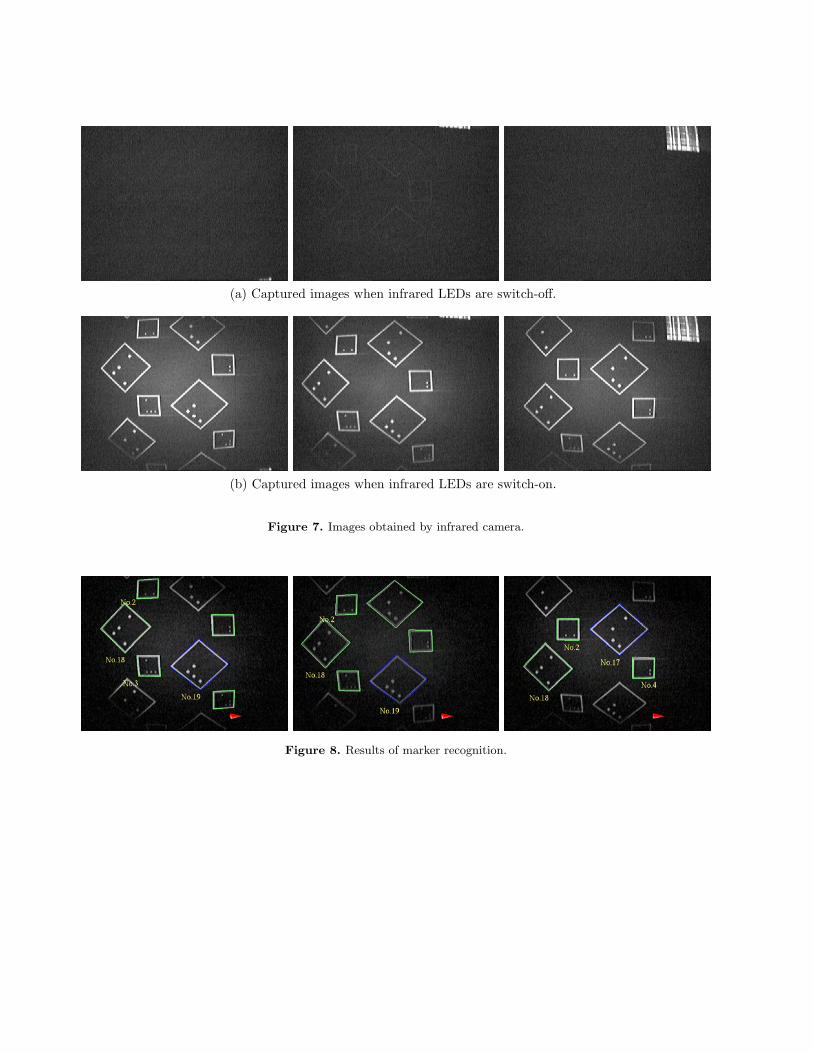
In this experiment, we confirm that the proposed system recognizes position IDs from the markers without powersupply of infrastructures and undesirable visual effects in the real scene . When the infrared LEDs are switch-off,retro-reflective markers are not captured as shown in Figure 7(a). On the other hand, when infrared LEDs areswitch-on, the markers are clearly captured as shown in Figure 7(b). Figure 8 shows results of marker recognition.These images were generated by recognizing subtraction images between Figures 7(a) and 7(b). Note that theposition IDs associated with the markers, and cones representing the direction of user are superimposed on thesubtraction images. We confirm that the ID of marker can be recognized. The system can calculate the relativeposition and direction of camera with respect to the marker coordinate system. The processing rate is about15 frames per second, because two images when the infrared LEDs are switch-on and switch-off are required forrecognition.
(a) Captured images when infrared LEDs are switch-off.
(b) Captured images when infrared LEDs are switch-on.
Figure 7. Images obtained by infrared camera.
Figure 8. Results of marker recognition.
x
52
[cm]
y
60[cm] 120[cm] 180[cm]
-0[cm] 150[cm]
(0,0)
30[cm]
104 [cm]
240[cm]
210[cm]
300[cm]
270[cm]
x
52
[cm]
y
60[cm] 120[cm] 180[cm]
-0[cm] 150[cm]
(0,0)
30[cm]
104 [cm]
240[cm]
210[cm]
300[cm]
270[cm]
Figure 9. Layout of markers.
3.2. Accuracy evaluation of localization results
In this experiment, we evaluate accuracy of the proposed system. The markers are set up on the ceilings, asshown in Figure 9. We employ two different size markers to recognize the markers even if the distance between acamera and markers is changed. The edge length of the small marker is 16cm and the size of its square elementallocated on the grids is 1cm × 1cm. On the other hand, the large marker’s edge length is 28cm, and the size ofits square element is 2cm × 2cm. The both markers’ frame width is 1cm. The number of grids N in the markerpattern is 4 as in Figure 3.
Marker
Camera
Figure 10. Estimated camera position and orientation.
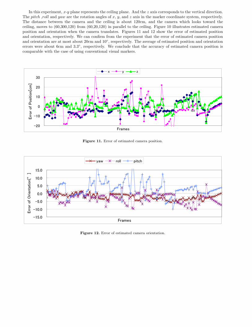
In this experiment, x-y plane represents the ceiling plane. And the z axis corresponds to the vertical direction.The pitch ,roll and yaw are the rotation angles of x, y, and z axis in the marker coordinate system, respectively.The distance between the camera and the ceiling is about 120cm, and the camera which looks toward theceiling, moves to (60,300,120) from (60,20,120) in parallel to the ceiling. Figure 10 illustrates estimated cameraposition and orientation when the camera translates. Figures 11 and 12 show the error of estimated positionand orientation, respectively. We can confirm from the experiment that the error of estimated camera positionand orientation are at most about 20cm and 10◦, respectively. The average of estimated position and orientationerrors were about 6cm and 3.3◦, respectively. We conclude that the accuracy of estimated camera position iscomparable with the case of using conventional visual markers.
-20
-10
0
10
20
30
1 26 51 76 101
Frames
Err
or
of
Positio
n[c
m]
x y z
Figure 11. Error of estimated camera position.
-15.0
-10.0
-5.0
0.0
5.0
10.0
15.0
1 26 51 76 101
Frames
Err
or
of
Orienta
tion[°
]
yaw roll pitch
Figure 12. Error of estimated camera orientation.
4. CONCLUSION
This paper has proposed a new localization method using invisible markers and infrared camera. In our method,user’s position is identified by recognizing translucent retro-reflective markers which are illuminated from infraredLEDs. In order to eliminate the influence of infrared other than the reflection from retro-reflective markers, theinfrared LEDs are flashed on and off synchronously with image capturing.
In the experiments, we have confirmed that the accuracy of estimated camera position and orientation arecomparable with the case of using conventional visual markers. In future work, we should carry out experimentsat the extensive indoor environments. We will also improve the accuracy by considering the reliability of themarker’s position on a captured image.
ACKNOWLEDGMENTS
This research was supported in part by Core Research for Evolutional Science and Technology (CREST) Program“Advanced Media Technology for Everyday Living” of Japan Science and Technology Agency (JST).
REFERENCES1. S. Mann, “Wearable computing: A first step toward personal imaging,” IEEE Computer 30(2), pp. 25–32,
2002.2. R. Azuma, “A survey of augmented reality,” Presence Vol. 6(No. 4), pp. 355–385, 1997.3. M. Kanbara, T. Okuma, H. Takemura, and N. Yokoya, “A stereoscopic video see-through augmented reality
system based on real-time vision-based registration,” Proc.IEEE Int. Conf. on Virtual Reality 2000 , pp. 255–262, 2000.
4. S. Julier, M. Lanzagorta, Y. Baillot, L. Rosenblum, S. Feiner, T. Holler, and S. Sestito, “Information filteringfor mobile augmented reality,” Proc. 1st IEEE/ACM Int. Symp. on Augmented Reality , pp. 3–11, 2000.
5. H6. R. Malaka and A. Zipf, “Deep map - challenging it research in the framework of a tourist information
system,” Proc. 7th Int. Congress on Tourism and Comm. , pp. 15–27, 2000.7. P. Daehne and J. Karigiannis, “Archeoguide: System architectureof a mobile outdoor augmented reality
system,” Proc. 1st IEEE/ACM Int. Symp. on Mixed and Augmented Reality , pp. 263–264, 2002.8. R. Tenmoku, Y. Nakazato, A. Anabuki, M. Kanbara, and N. Yokoya, “Nara palace site navigator: Device-
independent human navigation using a networked shared database,” Proc.10th Int. Conf. on Virtual Systemsand Multimedia , pp. 1234–1242, 2004.
9. M. Kourogi and T. Kurata, “Personal positioning based on walking locomotion analysis with self-containedsensors and wearable camera,” Proc. 2nd IEEE/ACM Int. Symp. on Mixed and Augmented Reality , pp. 103–112, 2003.
10. L. Vacchetti, V. Lepetit, and P. Fua, “Combining edge and texture information for real-time accurate 3dcamera tracking,” Proc. 3rd IEEE/ACM Int. Symp. on Mixed and Augmented Reality , pp. 48–57, 2004.
11. R. Tenmoku, M. Kanbara, and N. Yokoya, “A wearable augmented reality system using positioning infras-tructures and a pedometer,” Proc. IEEE Int. Symp. on Wearable Computers , pp. 110–117, 2003.
12. M. Maeda, T. Ogawa, K. Kiyokawa, and H. Takemura, “Tracking of user position and orientation by stereomeasurement of infrared markers and orientation sensing,” Proc. IEEE Int. Symp. on Wearable Computers, pp. 77–84, 2004.
13. G. Baratoff, A. Neubeck, and H. Regenbrecht, “Interactive multi-marker calibration for augmented realityapplications,” Proc. 1st IEEE/ACM Int. Symp. on Mixed and Augmented Reality , pp. 107–116, 2002.
14. L. Naimark and E. Foxlin, “Circular data matrix fiducial system and robust image processing for a wearablevision-inertial self-tracker,” Proc. 1st IEEE/ACM Int. Symp. on Mixed and Augmented Reality , pp. 27–36,2002.
15. H. Kato and H. Billinghurst, “Marker tracking and hmd calibration for a video-based augmented realityconferencing system,” Proc. 2nd IEEE/ACM Int. Workshop on Augmented Reality , pp. 85–94, 1999.