I 67-FE-24 $1.50 PER COpy 75C TO ASME MEMBERS The Society shall not be responsible for state· ments or opinions advanced in papers or in dis· . cussion at meetings of the Society or of its Divisions or Sections, or printed in its publicatio!1s . Discussion is printed only if the paper is . published in an AS ME iournal or Proceedings. Released for general publication upon presentation Loc ked -in Vortex S hedding B ehind Oscilla t ing Circular C ylinders, with Applic at i on to T ransmissio n Lines 1 J. H. LIENHARD Associate Professor, Mechanical Engineering, Washington State University, Pullman, Wash. Mem. ASME. l. W. UU2 Engineer, The Boeing Company, Seattle, Wash. The vortex shedding frequency has been measured for a water flow over cylinders undergoing forced vibration normal to the flow. A Reynolds number range of 970 ::; Re 24,BOO and an amplitude·to·diameter ratio of Va were employed in the tests. The results show that the vortex frequency locks in on the cylinder frequency over a frequency band whose width varies with Reynolds number. Locking·in also appears to occur over narrower bands at certain multiples and submultiples of the cylinder frequency . Steidel's transmission-line data ore rationalized on the basis of these data. 1 This work has been supported jointly by tbe Bonneville Power Administration and tbe College of Engineering Research Division at Washington State University. 2Formerly, Research Assistant, Mechanical Engineering Department, Wasbington State University. For presentation at the Fluids Engineering Conference, Chicago, III., May 8-11, 1967, of The American Society of Mechanical Engineers. Manuscript received at ASME Headquarters, March 3, 1967. Copies will be available until March 1, 1968. THE AMERICAN SOCIETY OF MECHANICAL ENGINEERS, UNITED ENGINEERING CENTER, 345 EAST 47th STREET, NEW YORK, N.Y. 10017
Transcript
I 67-FE-24
$150 PER COpy
75C TO ASME MEMBERS
The Society shall not be responsible for statemiddot ments or opinions advanced in papers or in dismiddot cussion at meetings of the Society or of its Divisions or Sections or printed in its publicatio1s
Discussion is printed only if the paper is published in an AS ME iournal or Proceedings
Released for general publication upon presentation
Locked-in Vortex Shedding Behind Oscillating Circular Cylinders with Application to Transmission Lines1
J H LIENHARD Associate Professor Mechanical
Engineering Washington State
University Pullman Wash
Mem ASME
l W UU2
Engineer The
Boeing Company
Seattle Wash
The vortex shedding frequency has been measured for a water flow over cylinders
undergoing forced vibration normal to the flow A Reynolds number range of 970
Re ~ 24BOO and an amplitudemiddottomiddotdiameter ratio of Va were employed in the tests
The results show that the vortex frequency locks in on the cylinder frequency over
a frequency band whose width varies with Reynolds number Lockingmiddotin also appears
to occur over narrower bands at certain multiples and submultiples of the cylinder
frequency Steidels transmission-line data ore rationalized on the basis of these data
1This work has been supported jointly by tbe Bonneville Power Administration and tbe College of Engineering Research Division at Washington State University
2Formerly Research Assistant Mechanical Engineering Department Wasbington State University
For presentation at the Fluids Engineering Conference Chicago III May 8-11 1967 of The American Society of Mechanical Engineers Manuscript received at ASME Headquarters March 3 1967
Copies will be available until March 1 1968
THE AMERICAN SOCIETY OF MECHANICAL ENGINEERS UNITED ENGINEERING CENTER 345 EAST 47th STREET NEW YORK NY 10017
Locked-in Vortex Shedding Behind Oscillating Circular Cylinders withApplication to Transmission Lines J H LIEN HARD L W lIU
NOMENCLATURE A amplitude of vibration of cylshy
inder D diameter of cylinder f frequency
fv frequency of vortex shedding
fv frequency of vortex sheddingo
behind a stationary cylinder
fI frequency of input cylinder vibration
6fv difference between frequency at end of locked-in region and
fv o fn denoting an arbitrary function Re Reynolds number Uoo D 1)
S Strouhal number fUooD Strouhal numbers based uponSv SVo SI 6Sv fv fv fI and 6fvo
U free stream velocity of liquid cross flow over cylinder kinematic viscosity
INTRODUCTION
The prediction of the frequency of aeolian vibration of freely suspended cables is a problem of great practical importance Such lines will vibrate at one of many closely spaced natural frequencies The difficulty is that of finding which frequency the line willmiddot choose under the influence of the wind
We have sought to answer this question by inverting it as follows What will be the freshyquency of vortex shedding fv behind a circular cylinder vibrating at frequency f I and how will this fv relate to the frequency fv o for a stashytionary cylinder The vortex shedding frequency in such an experiment will depend upon the inshyput frequency f I the kinematic viscosity V of the fluid the amplitude A of imposed vibration the normal velocity Uoo of the fluid far from the cylinder and the diameter D of the cylinshyder Dimensional analysis shows that
(1 )
1
~ ~
o 9ISI-Of AN D HASSANS OATA~ ~ J )- 020
00 ~~
~~ 0gt J Q 010
I I I
9000
I IREYNOLOS NUMBER R ~~
Fig 1 Bishop and Hassans locked-in regime
oIhere S is the Strouhal number fUooD and Re is the Reynolds number Uoo DV
Bishop and Hassan (l)3 studied lift and drag forces in an experiment of this kind They found that the frequencies fv are usually very nearly equal to f vo However when fI falls in a band surrounding fvo or certain of its multiples then fv will lock-in on fl It is thus poss ible to eliminate a variable from equation (1) by considshyering only the locked-in range 6Sv or 6fv above andor below Thusf vo
6SVSV ~ fn(Re AD) (2)o
Bishop and Hassan ill us trated this relation over narrow ranges of Re and AD with 7 data points shown in Figl These data imply that the influence of AD is weak especially when its lJlagnitude is small and they indicate that 6fv drops with increasing Re We wish to extend the mapping of this locked-in regime and to show how it relates to aeolian vibration In doing this we (like Bishop and Hassan) have used simpleshyharmonic motion to approximate what is more of a
----3-Underlined numbers in parentheses designate
References at the end of the paper
~~__~__~~ __L-~~
0 2 IU o~ 0
FRONT VIEW OF ECCENTRIC DEVICE
Fig2 Vibrating cylinder and flume apparatus
VARIABLE
THERMISTORS
SYNCHRONIZER
OSCIUATOR
UNIVERSAL AMPUFlER UNIT
Fig3 Thermistor velocity-recording device
figure-eight motion in the case of aeolian v i bra shytion
EXPERliVlENT
Details of the experiment -- given ful ly in reference (~) -- will be sketched briefly here An osc illat ing cylinder dr iven by a variable shyspeed motor moves up and down in a wat er flume as shoHI1 in Fig2 The adjustable eccentric mechshyanism (shown in Fig2) i s a slider-crank device with a crank -to-connect ing-rod ratio that is alshyways less than 0 20 Accordingly the simple harmonic motion i s a lmost perfect The Hat er flume is 17 i n high 12 in wide and 28 ft long with the cylinder located a bout 8 ft from the downstream end
Two schemes were us ed to determine the vorshytex frequency behind the cylinder At low flow velocities hydrogen bubbles were used to mark the flow and a v is ua l count of vortices was timed with a stop watch At higher velocities a homemade
bull o~~__
o ~
STROl1AL NtllroIBEA OF NT v iBAAnON $
Fig4 Influence of cylinder frequency upon vortex frequency 6 typical cases AID = O 125
hot-wire anemometer was used for this purpose This device employed two thermistors in place of conventional hot wires These were placed one diameter apart (in the upper and lower vort ex trails) a nd betwe en 4 and 6 diameters downstream The circuitry for this device is shown in Fig3
The thermistors compensated one another for temperature and to some extent for effects of gross cylinder motion The vortex shedding freshyquency could thus be counted direc tly from an os shycillograph without any calibration These obsershyvations were consistent with the v i sual observashytions made in the low-velocity range The probshyable error of both schemes was found to be about 3 percent
Sets of data were obta ined by va rying fI with Uoo and D held constant The ratio AD was adjusted to 0125 in all of the work reported here This is a reasonable va lue for the aeolian vibration of large transmission-line conductors It also provides a way of checking the relatively minor dependence of 6S vSv upon AD beyond
oBishop and Hassan I s rang e
Typical plots of Sv versus SI are given for six Reynolds numbers in Fig4 In each case Sv is general ly equal to approximately Svo except in regions in which it is a multiple or a submulshytiple of SI These locked-in regions are compara shytively indistinct Hith the exception of the funshydamental one fv = fl The lesser ones that apshypeared repeatedly were fI ~ 055f v fI ~ 22fv fI =30f and fI =44fv The reader Hill notev
RESISTOR~
~
I
2
0 6 ~
shy 04ltl
Igt 0
gt0 02 Vl
~ Vl ltl
z ~
-02 w Igt
~ I -040
w
U 0 J -06
~ir-~ ~1-bJ~
rh-l~L---DATA OF BISHOP AND HASSAN REGION BETWEEN LOCKED-IN ANDIl UNLOCKED-N RANGES AND 2nd SETS OF DATA RESPECTIVELY
PROBABLE ERROR
4000 8000 2000 6000 20000 24000 28000
REYNOLDS NUMBER R
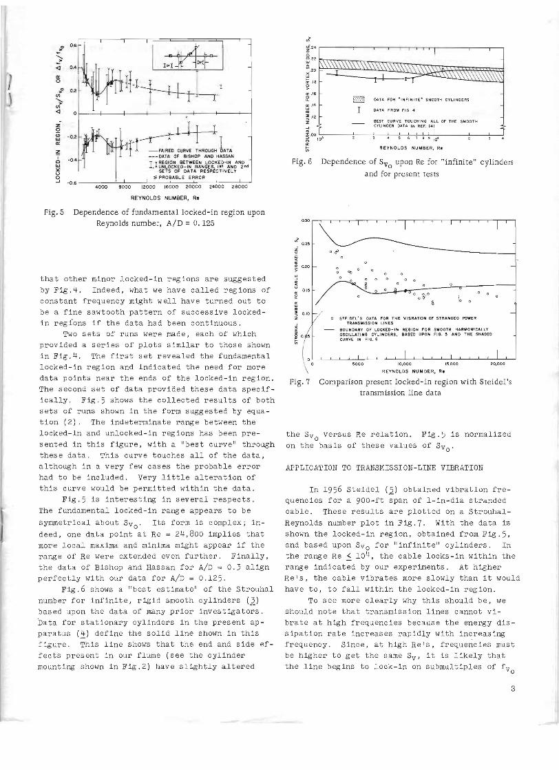
Fig 5 Dependence of fundamental locked-in region upon Reynolds number AID = O 125
that other minor locked-in regions are suggested by Fig4 Indeed what we have called regions of constant frequency might well have turne d out to be a fine sawtooth pattern of successive lockedshyin regions if the data had been continuous
Two sets of runs were made each of which provided a series of plots similar to those shown in Fig4 The first set rev ea led the fundamental locked-in region and indicated the need for more data points near the ends of the locked-in region The second set of data provided these data specifshyically Fig5 shows the collected results of both sets of runs shown in the form suggested by equashytion (2) The indeterminate range between the l ocked-in and unlocked-in reg ions has been preshysented in this figure with a best curve through these data This curve touches all of the data although in a very few cases the probable error had to be included Very little alteration of this curve would be permitted within the data
Fig5 is interesting in several respects The fundamental locked-in range appears to be
symmetrical about SV Its form is complex inshyo deed one data pOint at Re = 24800 implies that more local maxima and minima might appear if the range of Re were extended even further Finally the data of Bishop and Hassan for AID = 03 align perfectly with our data for AID = 0125
Fig6 shows a best estimate of the Strouhal number for infinite rigid smooth cylinders (2) based upon the data of many prior investigators bata for stationary cylinders in the present apshyparatus (~) define the solid line shown in this figure This line shows that the end and side efshyfects present in our flume (see the cylinder mounting shown in Fig2) have slightly altered
gt Vgt
g24 ------------r---i-------------- ()20~22~~~~ ~ tl 19 o gt Il 16 e ~ DATA FOR middotNFINITe SMOOTH CYLINDERS
~ 14 I DATA FROM FIG 4
~ 2 BEST CURVE TOUCHING ALL OF THE SMOOT H CY UNOER DATA IN REF (41
z - laquo ~OO ~---~-~-~-7-7-7~~~--~~-~~6 IO~ 5 6 r 8 3 104
0
REYNOLDS NUMBER Re
Fig 6 Dependence of SVo upon Re for infinite cylinders
and for present tests
t ~ CD 020
~ l II OI~
~ ~
ltD
~
oJ
o 0
sect o 0
[0 0
o STEIDELS QUA f OR THE VIBRATION OF STRANDED POWER TRANSMISSION LINES
BOUNDARY Of LOCIltEO-IN REGION FOR SlilOOTH HARMONICALLY OSCILLATING CYLINDERS BASED UPON FIG AND THE SHADED CURVE IN fl G 6
5000 10000 15000 20000
RE YNOLDS NU OER R
Comparison present locked-in region with SteidelsFig 7 transm ission line da ta
the SVo versus He relation Fig5 is normalized on the basis of these values of SV o
APPLICATION TO TRANSMISSION-LINE VIBRATION
In 1956 Steidel (2) obtained vibration freshyquencies for a 900-ft span of l-in-dia stranded cable These results are plotted on a StrouhalshyReynolds number plot in Fig 7 With the data 1-s shown the locked-in region obtained from Fig 5 and based upon SVo for infinite cylinders In the range Re ~ 104 the cable locks-in within the range indicated by our experiments At higher Res the cable vibrates more slowly than it would have to to fall within the locked-in region
To see more clearly why this should be we should note that transmission lines cannot vishybrate at high freq uenc ies because the energy disshySipation rate increases rapidly with increasing frequency Since at high Res frequencies must be higher to get the same Sv it is likely that the line begins to lock-in on submultiples of fv
o
3
at these Re1s Conversely at low Re1s cables tend not to vibrate at very low frequencies (ie in very long lOops) Thus vibration frequencies seek the upper end of the fundamental locked-in region when Re is low
ACKNOW LEDGr1ENTS
We are grateful to A R Hard and W S Chiu for their contributions to this investiga tion and to the R L Albrook Hydraulic Laboratory for housing and maintaining the apparatus
REFERENCES
1 R E D Bishop and A Y Hassan liThe Lift and Drag Forces on a Circular Cylinder Osshy
cillating in a FloHing Fluid II Proc Roy Soc A vol 277 1964 pp 51-75
2 L W Liu IITheoretical and Experimental Studies of the Vortex Shedding Action on Vibratory Cylinders1I MS Thesis Washington State Univershysity 1966 also progress report No 665-39 to Bonneville Power Administration
3 J H Lienhard IISynopsis of Lift Drag and Vortex Frequency Data for Rigid Circular Cylshyinders Washington State University College of Eng ineering Bulletin No 300 1966
4 J H Lienhard progress report No 665shy79 to Bonneville POHer Administration
5 R F Steidel Jr IIS ome Effects of Vorshytex Format ion in the Wake of a Suspended Cylindrishycal Cable1I Journal of Applied MechaniCS Vol 23 1956 pp 649-650
4
Locked-in Vortex Shedding Behind Oscillating Circular Cylinders withApplication to Transmission Lines J H LIEN HARD L W lIU
NOMENCLATURE A amplitude of vibration of cylshy
inder D diameter of cylinder f frequency
fv frequency of vortex shedding
fv frequency of vortex sheddingo
behind a stationary cylinder
fI frequency of input cylinder vibration
6fv difference between frequency at end of locked-in region and
fv o fn denoting an arbitrary function Re Reynolds number Uoo D 1)
S Strouhal number fUooD Strouhal numbers based uponSv SVo SI 6Sv fv fv fI and 6fvo
U free stream velocity of liquid cross flow over cylinder kinematic viscosity
INTRODUCTION
The prediction of the frequency of aeolian vibration of freely suspended cables is a problem of great practical importance Such lines will vibrate at one of many closely spaced natural frequencies The difficulty is that of finding which frequency the line willmiddot choose under the influence of the wind
We have sought to answer this question by inverting it as follows What will be the freshyquency of vortex shedding fv behind a circular cylinder vibrating at frequency f I and how will this fv relate to the frequency fv o for a stashytionary cylinder The vortex shedding frequency in such an experiment will depend upon the inshyput frequency f I the kinematic viscosity V of the fluid the amplitude A of imposed vibration the normal velocity Uoo of the fluid far from the cylinder and the diameter D of the cylinshyder Dimensional analysis shows that
(1 )
1
~ ~
o 9ISI-Of AN D HASSANS OATA~ ~ J )- 020
00 ~~
~~ 0gt J Q 010
I I I
9000
I IREYNOLOS NUMBER R ~~
Fig 1 Bishop and Hassans locked-in regime
oIhere S is the Strouhal number fUooD and Re is the Reynolds number Uoo DV
Bishop and Hassan (l)3 studied lift and drag forces in an experiment of this kind They found that the frequencies fv are usually very nearly equal to f vo However when fI falls in a band surrounding fvo or certain of its multiples then fv will lock-in on fl It is thus poss ible to eliminate a variable from equation (1) by considshyering only the locked-in range 6Sv or 6fv above andor below Thusf vo
6SVSV ~ fn(Re AD) (2)o
Bishop and Hassan ill us trated this relation over narrow ranges of Re and AD with 7 data points shown in Figl These data imply that the influence of AD is weak especially when its lJlagnitude is small and they indicate that 6fv drops with increasing Re We wish to extend the mapping of this locked-in regime and to show how it relates to aeolian vibration In doing this we (like Bishop and Hassan) have used simpleshyharmonic motion to approximate what is more of a
----3-Underlined numbers in parentheses designate
References at the end of the paper
~~__~__~~ __L-~~
0 2 IU o~ 0
FRONT VIEW OF ECCENTRIC DEVICE
Fig2 Vibrating cylinder and flume apparatus
VARIABLE
THERMISTORS
SYNCHRONIZER
OSCIUATOR
UNIVERSAL AMPUFlER UNIT
Fig3 Thermistor velocity-recording device
figure-eight motion in the case of aeolian v i bra shytion
EXPERliVlENT
Details of the experiment -- given ful ly in reference (~) -- will be sketched briefly here An osc illat ing cylinder dr iven by a variable shyspeed motor moves up and down in a wat er flume as shoHI1 in Fig2 The adjustable eccentric mechshyanism (shown in Fig2) i s a slider-crank device with a crank -to-connect ing-rod ratio that is alshyways less than 0 20 Accordingly the simple harmonic motion i s a lmost perfect The Hat er flume is 17 i n high 12 in wide and 28 ft long with the cylinder located a bout 8 ft from the downstream end
Two schemes were us ed to determine the vorshytex frequency behind the cylinder At low flow velocities hydrogen bubbles were used to mark the flow and a v is ua l count of vortices was timed with a stop watch At higher velocities a homemade
bull o~~__
o ~
STROl1AL NtllroIBEA OF NT v iBAAnON $
Fig4 Influence of cylinder frequency upon vortex frequency 6 typical cases AID = O 125
hot-wire anemometer was used for this purpose This device employed two thermistors in place of conventional hot wires These were placed one diameter apart (in the upper and lower vort ex trails) a nd betwe en 4 and 6 diameters downstream The circuitry for this device is shown in Fig3
The thermistors compensated one another for temperature and to some extent for effects of gross cylinder motion The vortex shedding freshyquency could thus be counted direc tly from an os shycillograph without any calibration These obsershyvations were consistent with the v i sual observashytions made in the low-velocity range The probshyable error of both schemes was found to be about 3 percent
Sets of data were obta ined by va rying fI with Uoo and D held constant The ratio AD was adjusted to 0125 in all of the work reported here This is a reasonable va lue for the aeolian vibration of large transmission-line conductors It also provides a way of checking the relatively minor dependence of 6S vSv upon AD beyond
oBishop and Hassan I s rang e
Typical plots of Sv versus SI are given for six Reynolds numbers in Fig4 In each case Sv is general ly equal to approximately Svo except in regions in which it is a multiple or a submulshytiple of SI These locked-in regions are compara shytively indistinct Hith the exception of the funshydamental one fv = fl The lesser ones that apshypeared repeatedly were fI ~ 055f v fI ~ 22fv fI =30f and fI =44fv The reader Hill notev
RESISTOR~
~
I
2
0 6 ~
shy 04ltl
Igt 0
gt0 02 Vl
~ Vl ltl
z ~
-02 w Igt
~ I -040
w
U 0 J -06
~ir-~ ~1-bJ~
rh-l~L---DATA OF BISHOP AND HASSAN REGION BETWEEN LOCKED-IN ANDIl UNLOCKED-N RANGES AND 2nd SETS OF DATA RESPECTIVELY
PROBABLE ERROR
4000 8000 2000 6000 20000 24000 28000
REYNOLDS NUMBER R
Fig 5 Dependence of fundamental locked-in region upon Reynolds number AID = O 125
that other minor locked-in regions are suggested by Fig4 Indeed what we have called regions of constant frequency might well have turne d out to be a fine sawtooth pattern of successive lockedshyin regions if the data had been continuous
Two sets of runs were made each of which provided a series of plots similar to those shown in Fig4 The first set rev ea led the fundamental locked-in region and indicated the need for more data points near the ends of the locked-in region The second set of data provided these data specifshyically Fig5 shows the collected results of both sets of runs shown in the form suggested by equashytion (2) The indeterminate range between the l ocked-in and unlocked-in reg ions has been preshysented in this figure with a best curve through these data This curve touches all of the data although in a very few cases the probable error had to be included Very little alteration of this curve would be permitted within the data
Fig5 is interesting in several respects The fundamental locked-in range appears to be
symmetrical about SV Its form is complex inshyo deed one data pOint at Re = 24800 implies that more local maxima and minima might appear if the range of Re were extended even further Finally the data of Bishop and Hassan for AID = 03 align perfectly with our data for AID = 0125
Fig6 shows a best estimate of the Strouhal number for infinite rigid smooth cylinders (2) based upon the data of many prior investigators bata for stationary cylinders in the present apshyparatus (~) define the solid line shown in this figure This line shows that the end and side efshyfects present in our flume (see the cylinder mounting shown in Fig2) have slightly altered
gt Vgt
g24 ------------r---i-------------- ()20~22~~~~ ~ tl 19 o gt Il 16 e ~ DATA FOR middotNFINITe SMOOTH CYLINDERS
~ 14 I DATA FROM FIG 4
~ 2 BEST CURVE TOUCHING ALL OF THE SMOOT H CY UNOER DATA IN REF (41
z - laquo ~OO ~---~-~-~-7-7-7~~~--~~-~~6 IO~ 5 6 r 8 3 104
0
REYNOLDS NUMBER Re
Fig 6 Dependence of SVo upon Re for infinite cylinders
and for present tests
t ~ CD 020
~ l II OI~
~ ~
ltD
~
oJ
o 0
sect o 0
[0 0
o STEIDELS QUA f OR THE VIBRATION OF STRANDED POWER TRANSMISSION LINES
BOUNDARY Of LOCIltEO-IN REGION FOR SlilOOTH HARMONICALLY OSCILLATING CYLINDERS BASED UPON FIG AND THE SHADED CURVE IN fl G 6
5000 10000 15000 20000
RE YNOLDS NU OER R
Comparison present locked-in region with SteidelsFig 7 transm ission line da ta
the SVo versus He relation Fig5 is normalized on the basis of these values of SV o
APPLICATION TO TRANSMISSION-LINE VIBRATION
In 1956 Steidel (2) obtained vibration freshyquencies for a 900-ft span of l-in-dia stranded cable These results are plotted on a StrouhalshyReynolds number plot in Fig 7 With the data 1-s shown the locked-in region obtained from Fig 5 and based upon SVo for infinite cylinders In the range Re ~ 104 the cable locks-in within the range indicated by our experiments At higher Res the cable vibrates more slowly than it would have to to fall within the locked-in region
To see more clearly why this should be we should note that transmission lines cannot vishybrate at high freq uenc ies because the energy disshySipation rate increases rapidly with increasing frequency Since at high Res frequencies must be higher to get the same Sv it is likely that the line begins to lock-in on submultiples of fv
o
3
at these Re1s Conversely at low Re1s cables tend not to vibrate at very low frequencies (ie in very long lOops) Thus vibration frequencies seek the upper end of the fundamental locked-in region when Re is low
ACKNOW LEDGr1ENTS
We are grateful to A R Hard and W S Chiu for their contributions to this investiga tion and to the R L Albrook Hydraulic Laboratory for housing and maintaining the apparatus
REFERENCES
1 R E D Bishop and A Y Hassan liThe Lift and Drag Forces on a Circular Cylinder Osshy
cillating in a FloHing Fluid II Proc Roy Soc A vol 277 1964 pp 51-75
2 L W Liu IITheoretical and Experimental Studies of the Vortex Shedding Action on Vibratory Cylinders1I MS Thesis Washington State Univershysity 1966 also progress report No 665-39 to Bonneville Power Administration
3 J H Lienhard IISynopsis of Lift Drag and Vortex Frequency Data for Rigid Circular Cylshyinders Washington State University College of Eng ineering Bulletin No 300 1966
4 J H Lienhard progress report No 665shy79 to Bonneville POHer Administration
5 R F Steidel Jr IIS ome Effects of Vorshytex Format ion in the Wake of a Suspended Cylindrishycal Cable1I Journal of Applied MechaniCS Vol 23 1956 pp 649-650
4
at these Re1s Conversely at low Re1s cables tend not to vibrate at very low frequencies (ie in very long lOops) Thus vibration frequencies seek the upper end of the fundamental locked-in region when Re is low
ACKNOW LEDGr1ENTS
We are grateful to A R Hard and W S Chiu for their contributions to this investiga tion and to the R L Albrook Hydraulic Laboratory for housing and maintaining the apparatus
REFERENCES
1 R E D Bishop and A Y Hassan liThe Lift and Drag Forces on a Circular Cylinder Osshy
cillating in a FloHing Fluid II Proc Roy Soc A vol 277 1964 pp 51-75
2 L W Liu IITheoretical and Experimental Studies of the Vortex Shedding Action on Vibratory Cylinders1I MS Thesis Washington State Univershysity 1966 also progress report No 665-39 to Bonneville Power Administration
3 J H Lienhard IISynopsis of Lift Drag and Vortex Frequency Data for Rigid Circular Cylshyinders Washington State University College of Eng ineering Bulletin No 300 1966
4 J H Lienhard progress report No 665shy79 to Bonneville POHer Administration
5 R F Steidel Jr IIS ome Effects of Vorshytex Format ion in the Wake of a Suspended Cylindrishycal Cable1I Journal of Applied MechaniCS Vol 23 1956 pp 649-650