i LOGO! manual EWA 4NEB 712 6006-02 Welcome to LOGO! Dear customer, Thank you for purchasing LOGO!, and congratulations on your decision. In LOGO! you have acquired a logic module that meets the stringent qual- ity requirements of ISO 9001. LOGO! is universal in application. Its comprehensive functionality and great ease of use make it a highly cost-efficient solution for virtually any application. LOGO! documentation This LOGO! manual tells you how to install, progam and use LOGO!. In addition, the step-by-step graphical guide shipped with LOGO! and the LOGO!Soft online help system provide you with the essentials. LOGO!Soft is a programming package that runs on PCs under WindowsT . It will help you get to know LOGO! and test, print and archive programs. Guide to the manual We have subdivided this manual into 6 chapters: S Getting to know LOGO! S Installing and wiring LOGO! S Programming LOGO! S Parameterizing LOGO! S Applications S Technical data Additional support If you have any questions concerning LOGO!, the dealer from whom you bought it will be glad to help you. Safety guidelines This manual contains notices which you should observe to ensure your own personal safety, as well as to protect the product and connected equipment. These notices are highlighted in the manual by a warning triangle and are marked as follows according to the level of danger:
Transcript
iLOGO! manualEWA 4NEB 712 6006-02
Welcome to LOGO!Dear customer,
Thank you for purchasing LOGO!, and congratulations on your decision.In LOGO! you have acquired a logic module that meets the stringent qual-ity requirements of ISO 9001.
LOGO! is universal in application. Its comprehensive functionality andgreat ease of use make it a highly cost-efficient solution for virtually anyapplication.
LOGO! documentation
This LOGO! manual tells you how to install, progam and use LOGO!.
In addition, the step-by-step graphical guide shipped with LOGO! and theLOGO!Soft online help system provide you with the essentials.LOGO!Soft is a programming package that runs on PCs under Windows .It will help you get to know LOGO! and test, print and archive programs.
Guide to the manual
We have subdivided this manual into 6 chapters:
� Getting to know LOGO!� Installing and wiring LOGO!
� Programming LOGO!
� Parameterizing LOGO!� Applications
� Technical data
Additional support
If you have any questions concerning LOGO!, the dealer from whom youbought it will be glad to help you.
Safety guidelinesThis manual contains notices which you should observe to ensure your own personalsafety, as well as to protect the product and connected equipment. These notices arehighlighted in the manual by a warning triangle and are marked as follows accordingto the level of danger:
LOGO! manualEWA 4NEB 712 6006-02
ii
!Dangerindicates that death, severe personal injury or substantial property dam-age will result if proper precautions are not taken.
!Warningindicates that death, severe personal injury or substantial property dam-age can result if proper precautions are not taken.
!Cautionindicates that minor personal injury or property damage can result ifproper precautions are not taken.
Notedraws your attention to particularly important information on the prod-uct, handling the product, or to a particular part of the documentation.
!WarningOnly qualified personnel should be allowed to install and work on thisequipment. Qualified persons are defined as persons who are authorizedto commission, to ground, and to tag circuits, equipment, and systems inaccordance with established safety practices and standards.
!WarningThis device and its components may only be used for the applicationsdescribed in the catalog or the technical description, and only in connec-tion with devices or components from other manufacturers which havebeen approved or recommended by Siemens.This product can only function correctly and safely if it is transported,stored, set up, and installed correctly, and operated and maintained asrecommended.
Copyright � Siemens AG 1996 All rights reservedThe reproduction, transmission or use of this document or its contents is not permitted withoutexpress written authority. Offenders will be liable for damages. All rights, including rights created
Disclaimer of LiabilityWe have checked the contents of this manual for agreement with the hardware and softwaredescribed. Since deviations cannot be precluded entirely, we cannot guarantee full agreement.However, the data in this manual are reviewed regularly and any necessary corrections includedin subsequent editions. Suggestions for improvement are welcomed.
3.12 Using the program module/card 59. . . . . . . . . . . . . . . . 3.12.1 Removing the program module/card 60. . . . . . . . . . . . . 3.12.2 Copying a program from LOGO! to the program
module/card 61. . . . . . . . . . . . . . . . . . . . . . . . . . . . . . . . . . 3.12.3 Copying a program from the program module/card
1 Getting to know LOGO!What is LOGO! ? – LOGO! is the new universal logic module from Siemens.
With dimensions of 72 x 90 x 55 mm, LOGO! provides:� Control functions
� An operating and display unit
� A power supply� 6 inputs and 4 outputs
� An interface for program modules and a PC cable
� Ready-to-use basic functions that are often required in practice, such asfunctions for on- and off-delays and pulse relays
� A time switch/clock (LOGO! 230RC)
L1 N �� �� �� �� �� I6
Q1 Q2 Q3 Q4
SIEMENS
Inputs
Outputs
Power supply
Display panel
Keys
Shaft forprogrammodule andPC cable
You can use LOGO! for domestic and installation engineering tasks (e.g.stairway lighting, external lighting, sun blinds, shutters or shop windowlighting) and for mechanical and apparatus engineering (e.g. gate controlsystems, ventilation systems or rainwater pumps).
LOGO! manualEWA 4NEB 712 6006-02
2
Versions
The following different versions of LOGO! are available:
� LOGO! 230 RC– Power supply and digital inputs: 115 V AC / 230 V AC
– Digital outputs: relays, max. 8 A
– 4 time switches (clocks) with up to 3 on and off times each� LOGO 230R
– Power supply and digital inputs: 115 V AC / 230 V AC
– Digital outputs: relays, max. 8 A� LOGO! 24R
– Power supply and digital inputs: 24 V DC
– Digital outputs: relays, max. 8 A� LOGO! 24
– Power supply and digital inputs: 24 V DC
– Digital outputs: transistor max. 0.3 A
LOGO! has UL, CSA and FM certification, carries CE marking, complieswith the VDE 0631 and IEC1131 standards and has interference suppres-sion in accordance with EN 55011 (limit class B).
Getting to know LOGO!
3LOGO! manualEWA 4NEB 712 6006-02
2 Installing and wiring LOGO!You install LOGO! in a distribution box or cabinet, ensuring that the con-nectors are covered. If they are not, there is a danger of touching liveparts.
LOGO! must be installed and wired by a trained technician who knowsand complies with both the universally applicable engineering rules andthe regulations and standards that apply in specific cases.
Dimensions
The dimensions of LOGO! comply with the DIN 43880 standard for thedimensions of installation equipment.
LOGO! must be snapped onto a DIN rail with a width of 35 mm(DIN EN 50022).
LOGO! is 72 mm wide, which corresponds to the size of 4 modules.
LOGO! manualEWA 4NEB 712 6006-02
4
2.1 Installing/deinstalling LOGO!
You install LOGO! on a DIN rail as follows:
1. Place LOGO! on the rail.
2. Swivel it. The snap catch on the back of LOGO! must engage.
Depending on the type of DIN rail used, the snapping mechanism may bea bit stiff. If it is too stiff and LOGO! will not snap on, you can pull thesnap catch down a little, as you do when deinstalling LOGO! as describedbelow.
You deinstall LOGO! as follows:
1. Insert a screwdriver in the hole shown in the picture at the lower end ofthe snap catch, and pull the snap catch downward.
1
2
RC
–004
9
2. Swivel LOGO! away from the DIN rail.
Installing and wiring LOGO!
5LOGO! manualEWA 4NEB 712 6006-02
2.2 Wiring LOGO!
Use a screwdriver with a head 3 mm wide to wire LOGO!.
You do not need wire end ferrules for the connectors. You can use wires upto the following sizes:
� 1 x 2.5 mm2
� 2 x 1.5 mm2
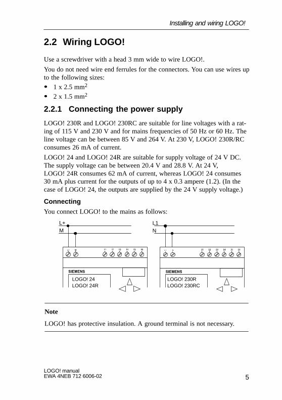
2.2.1 Connecting the power supply
LOGO! 230R and LOGO! 230RC are suitable for line voltages with a rat-ing of 115 V and 230 V and for mains frequencies of 50 Hz or 60 Hz. Theline voltage can be between 85 V and 264 V. At 230 V, LOGO! 230R/RCconsumes 26 mA of current.
LOGO! 24 and LOGO! 24R are suitable for supply voltage of 24 V DC.The supply voltage can be between 20.4 V and 28.8 V. At 24 V,LOGO! 24R consumes 62 mA of current, whereas LOGO! 24 consumes30 mA plus current for the outputs of up to 4 x 0.3 ampere (1.2). (In thecase of LOGO! 24, the outputs are supplied by the 24 V supply voltage.)
Connecting
You connect LOGO! to the mains as follows:
L1L+NM
LOGO! 24LOGO! 24R
LOGO! 230RLOGO! 230RC
Note
LOGO! has protective insulation. A ground terminal is not necessary.
Installing and wiring LOGO!
LOGO! manualEWA 4NEB 712 6006-02
6
2.2.2 Connecting LOGO!’s inputs
Requirements
You connect sensors to the inputs. The sensors may be switches, photo-electric barriers or daylight control switches, for example.
Sensor attributes for LOGO! 230R and LOGO! 230RC� LOGO! recognizes the switch state 0 (switch open) at � 40 V AC. The
maximum input current is 0.24 mA (switches with glow lamps cancause problems if the closed-circuit current of the glow lamps isgreater than 0.2 mA. Connect these switches to LOGO! via a relay, oruse switches where the glow lamp is connected via an additional n-typeconductor).
� LOGO! recognizes the switch state 1 (switch open) at � 79 V AC(switch closed).
� You cannot connect 2-wire proximity switches to LOGO! directly be-cause of their high closed-circuit current.
� When the switch state changes from 0 to 1, switch state 1 must existfor at least 50 ms for LOGO! to recognize it. The same applies to state0 when the change is in the opposite direction.
Sensor attributes for LOGO! 24 and LOGO! 24 R� LOGO! recognizes the switch state 0 (switch open) at � 5 V DC. The
input current is typically 3 mA.
� LOGO! recognizes the switch state 1 (switch closed) at � 15 V DC.
� You can connect 3- and 4-wire proximity switches with a separate volt-age supply to LOGO!. You cannot connect 2-wire proximity switchesto LOGO! directly because of their high closed-circuit current.
� When the switch state changes from 0 to 1, switch state 1 must existfor at least 50 ms for LOGO! to recognize it. The same applies to state0 when the change is in the opposite direction.
Installing and wiring LOGO!
7LOGO! manualEWA 4NEB 712 6006-02
Connecting
You connect the sensors to LOGO! as follows:
L1N
L+M
LOGO! 24/R LOGO! 230R/RC
L+ L+ L+ L+ L+ L+
!Warning
Existing safety regulations (VDE 0110, ... IEC 1131, ... and ULand CSA) prohibit the connection of different phases to the in-puts of LOGO! 230R/RC.
The inputs of LOGO! 24/24R are non-isolated and must therefore begrounded in the same way as the power supply.
Installing and wiring LOGO!
LOGO! manualEWA 4NEB 712 6006-02
8
2.2.3 Connecting outputs
LOGO! 230R, LOGO! 230RC and LOGO! 24R
The outputs of LOGO! 230R, LOGO! 230RC and LOGO! 24R are relays.The contacts of the relays are isolated from the power supply and the in-puts.
Requirements for the relay outputs
You can connect different loads to the outputs, such as lamps, fluorescenttubes, motors, contactors, etc. The loads connected to LOGO! 230R/RCand LOGO! 24R must have the following properties:� The maximum switched current depends on the type of load and the
number of operations. You will find more information on this in thetechnical specifications.
� When switched on (Q = 1), the maximum current is 8 amperes for anon-inductive load and 2 amperes for an inductive load.
Connecting
You connect the load to LOGO! 230 R/RC and LOGO! 24R as follows:
L1
N/M
Load
Protection with auto-matic circuit breaker(max. 16 A, B16), e.g. power circuitbreaker 5SX2 116-6
Installing and wiring LOGO!
9LOGO! manualEWA 4NEB 712 6006-02
LOGO! 24
The outputs of LOGO! 24 are switched by means of transistors. The out-puts are short circuit-proof and overload-proof. A separate voltage supplyto the load is not necessary; LOGO! 24 supplies the load with voltage.
Requirements for transistor outputs
The load connected to LOGO! 24 must have the following properties:
� The maximum switched current is 0.3 amperes.
� When switched on (Q = 1), the maximum current is 0.3 amperes.
Connecting
You connect the load to LOGO! 24 as follows:
Load24 V DC, 0,3 A (max.)
Installing and wiring LOGO!
LOGO! manualEWA 4NEB 712 6006-02
10
2.3 Switching LOGO! on/resumption of powersupply
LOGO! does not have a power switch. How LOGO! responds whenswitched on depends on:
� Whether a program is stored in LOGO!
� Whether a memory card is inserted� The state LOGO! was in before power off
The table indicates LOGO!’s responses to the possible situations:
If Then
LOGO! does not contain a programand there is no memory card inserted
The following appears on LOGO!’s dis-play: No Program
LOGO! does not contain a program,there is a memory card inserted, but thecard does not contain a program (emptymemory card)
The following appears on LOGO!’s dis-play: No Program
LOGO! does not contain a program,there is no or an empty memory cardinserted, and
1. LOGO! was in RUN or in parame-terization mode before power off
2. LOGO! was in programming modebefore power off LOGO!
LOGO! uses the stored program and
1. Goes into RUN
2. Goes into the main menu in pro-gramming mode
A memory card containing a programis inserted and
1. LOGO! was in RUN or in parame-terization mode before power off
2. LOGO! was in programming modeor No Program was displayed beforepower off
LOGO! copies the program from thememory card automatically and
1. Goes into RUN
2. Goes into the main menu in pro-gramming mode
Installing and wiring LOGO!
11LOGO! manualEWA 4NEB 712 6006-02
Try to remember the 4 simple rules for starting LOGO!:1. If there is no program in LOGO! or on the memory card, LOGO! dis-
plays the message: No Program
2. If there is a program on the memory card, it is copied to LOGO! auto-matically. If there is already a program in LOGO!, it is overwritten.
3. If there is a program in LOGO! or on the memory card, LOGO! adoptsthe operating status it had before power off.
4. The times and count values are reset at power off. The program is sto-red in such a way that it is secure against power failure.
Note
If a power failure occurs while you are entering a program, the programin LOGO! is deleted when the power is restored.
You should therefore back up your original program on a program module(card) before changing it.
LOGO! operating statuses
LOGO! has 2 operating statuses:
� STOP� RUN
LOGO! is in STOP when ’No Program’ is displayed or when you switch itto programming mode. In STOP:
� Inputs I1 to I6 are not read.
� The program is not executed.� The relay contacts of Q1 to Q4 are always open.
LOGO! is in RUN when ’RUN’ is displayed (after START in the mainmenu) or when you switch it to parameterization mode. In RUN, LOGO!
� Reads the statuses of inputs I1 to I6.
� Calculates (with the program) the status of the outputs.� Switches relays Q1 to Q4 on or off.
Installing and wiring LOGO!
LOGO! manualEWA 4NEB 712 6006-02
12
3 Programming LOGO!By programming, we mean entering a circuit. A LOGO! program is reallyno more than a circuit diagram represented in a different way.
We have changed the way it is represented to suit LOGO!’s display panel.
What does this chapter contain?
� It begins by telling you something about how a circuit is stored inLOGO!.
� It then introduces you to the blocks that exist in LOGO!.
� Finally, it contains an example illustrating how to enter a circuit inLOGO!.
13LOGO! manualEWA 4NEB 712 6006-02
3.1 Circuit diagram
You know, of course, how a circuit is represented in a circuit diagram.Here is an example:
K1
S1 K1S2
E1
The consumer E1 is switched on andoff by means of the switches S1 ORS2. The relay K1 picks up when S1or S2 is closed.
In LOGO! we use an OR block to represent this. Thus, the above circuit isrepresented as follows:
�1
�2
xQ1
�1
S2 S1
Wiring
Q1
Program Wiring
Corresponds toK1
LOGO! represents the parallel circuit of switches S1 and S2 as an ORblock.
Switch S1 is connected to connector I1 on LOGO!. Switch S2 is connectedto connector I2 on LOGO!. Only 2 inputs of the OR block are used, so thethird input must be marked as unused. This is indicated by the x next to it.
The output of the OR block controls the relay at output Q1. Consumer E1is connected at output Q1.
You now know the most important terms in relation to entering a circuit:connectors, blocks and block inputs.
Programming LOGO!
LOGO! manualEWA 4NEB 712 6006-02
14
3.2 Connectors and blocks
We would like to begin by showing you how we denote the connectors andblocks and by describing the function of the blocks. We will then showyou how to enter a circuit in LOGO!.
You do not necessarily have to work directly with LOGO! to enter a cir-cuit. Instead, you can use the LOGO! PC software. Ask your dealer aboutLOGO!Soft.
Programming LOGO!
15LOGO! manualEWA 4NEB 712 6006-02
3.3 Connectors
LOGO! has inputs and outputs:
Inputs
Outputs
L1 N �� �� �� �� �� I6
Q1 Q2 Q3 Q4
SIEMENS
Each input is identified by the letter I with a number. When you look atLOGO! from the front, you see the connectors for the inputs at the topright.
Each output is identified by the letter Q with a number. You will see theconnectors of the outputs at the bottom.
Connections when programming
When you program LOGO!, you connect connectors with blocks. To dothis, you simply select the connection you require from the Co menu (Costands for connector).
�1�2
x
�1Inputs I1 and I2 are connected to the ORblock here. The last input of the block is notused and is therefore marked with an x.
Q
LOGO! recognizes the following connectors:
� Inputs: I1, I2, I3, I4, I5, I6
� Outputs: Q1, Q2, Q3, Q4� lo: ‘0’ (OFF)
� hi: ’1’, (On)
� x: Not connected
Programming LOGO!
LOGO! manualEWA 4NEB 712 6006-02
16
The inputs and outputs can have the state ’0’ or ’1’. ’0’ means there is novoltage at the input, and ’1’ means that there is. But that is unlikely to benew to you.
We introduced the connectors hi, lo and x in order to facilitate programentry for you. ’hi’ has the fixed state ’1’, and ’lo” has the fixed state ’0’.
If you do not want to wire an input on a block, you use the ’x’ connector.
Programming LOGO!
17LOGO! manualEWA 4NEB 712 6006-02
3.4 Basic functions
When you enter a circuit, you will find the blocks for basic functions inthe GF list. The following basic functions exist:
Circuit diagramrepresentation
Representation inLOGO!
Basic function
Series connectionof normally opencontacts
AND
Parallel connectionof normally opencontacts
OR
Inverter
NOT
Double changeovercontact
XOR (exclusive or)
Parallel connection ofnormally closed contacts
NAND (and not)
Series connection of nor-mally closed contacts
NOR (or not)
Programming LOGO!
LOGO! manualEWA 4NEB 712 6006-02
18
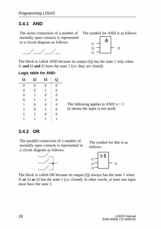
3.4.1 AND
I1
�2
I3
Q
The series connection of a number ofnormally open contacts is representedin a circuit diagram as follows:
The symbol for AND is as follows
The block is called AND because its output (Q) has the state 1 only whenI1 and I2 and I3 have the state 1 (i.e. they are closed).
The parallel connection of a number ofnormally open contacts is represented ina circuit diagram as follows:
The block is called OR because its output (Q) always has the state 1 whenI1 or I2 or I3 has the state 1 (i.e. closed). In other words, at least one inputmust have the state 1.
Programming LOGO!
The following applies to AND: x = 1(x means the input is not used)
19LOGO! manualEWA 4NEB 712 6006-02
Logic table for OR:
I1 I2 I3 Q
0 0 0 0
0 0 1 1
0 1 0 1
0 1 1 1
1 0 0 1
1 0 1 1
1 1 0 1
1 1 1 1
3.4.3 NOT
An inverter is represented in acircuit diagram as follows:
QI1
In LOGO! the inverter is calledNOT: The symbol for this is asfollows:
The block is called NOT because the output (Q) has the state 1 when theinput has the state 0, and vice versa. In other words, NOT inverts the stateat the input.
The advantage of NOT is, for example, that you no longer require any nor-mally closed contacts for LOGO!. You can use a normally open contactand convert it to a normally closed contact using the NOT block. The sym-bol for NOT is as follows:
Logic table for the NOT
I1 Q
0 1
1 0
Programming LOGO!
The following applies to OR: x = 0 (x means the input is not used)
The following applies to NOT: x = 1 (x means the input is not used)
LOGO! manualEWA 4NEB 712 6006-02
20
3.4.4 NAND
I1
I2
I3
Q
The parallel connection of a num-ber of normally closed contacts isrepresented in a circuit diagram asfollows:
In LOGO! this is a NAND block.The symbol for it is as follows:
The block is called NAND because its output (Q) only has the state 0 if I1and I2 and I3 have the state 1 (i.e. are closed).
Logic table for NAND
I1 I2 I3 Q
0 0 0 1
0 0 1 1
0 1 0 1
0 1 1 1
1 0 0 1
1 0 1 1
1 1 0 1
1 1 1 0
3.4.5 NOR
I1I2
I3Q
The series connection of a numberof normally closed contacts is rep-resented in a circuit diagram asfollows:
In LOGO! this is a NOR block. Thesymbol for NOR is as follows:
The output of the NOR block is only switched on (state 1) when all theinputs are switched off (state 0). As soon as any of the inputs is switchedon (state 1), the output is switched off.
Programming LOGO!
The following applies to NAND: x = 1 (x means the input is not used)
21LOGO! manualEWA 4NEB 712 6006-02
The block is called NOR because its output (Q) only has the state 1 whenall the inputs have the state 0. As soon as any of the inputs takes on thestate 1, the output of NOR has the state 0.
Logic table for NOR
I1 I2 I3 Q
0 0 0 1
0 0 1 0
0 1 0 0
0 1 1 0
1 0 0 0
1 0 1 0
1 1 0 0
1 1 1 0
3.4.6 XOR
An XOR in a circuit diagram is aseries connection of two change-over contacts:
QI1I2
In LOGO! the symbol for this is asfollows:
The output of XOR has the state 1 when the states of the inputs differ.
Logic table for XOR
I1 I2 Q
0 0 0
0 1 1
1 0 1
1 1 0
Programming LOGO!
The following applies to NOR: x = 0 (x means the input is not used)
The following applies to XOR: x = 0 (x means the input is not used)
LOGO! manualEWA 4NEB 712 6006-02
22
3.5 Special functions
When you enter a program in LOGO!, you will find the special functionsin the SF list. The following special functions exist:
Circuit diagramrepresentation
Representation inLOGO!
Special function
TrgT
On-delay
Trg
TR
Off-delay
TrgR
Pulse relay
No1
No3No2
Clock pulse generator
R
SK1
K1
RS
RS
Latching relay
EnT
Clock pulse generator
Programming LOGO!
23LOGO! manualEWA 4NEB 712 6006-02
Circuit diagramrepresentation
Special functionRepresentation inLOGO!
R K1
K1
K1Trg QTrg
TR
Retentive on-delay
RCntDirPar
Counter up and down
NoteIn all functions, R has priority over all other inputs.
Note
After a power failure/power restoration, in the case of time functions thetime that has elapsed is reset, and in the case of the counter the countedvalue is reset.
3.5.1 Accuracy of the time
All electronic components have minute differences. For this reason, smalldeviations from the time set (T) can occur. In LOGO!, the maximum devi-ation is 1 %.
Example:
In 1 hour (3600 seconds), the deviation is 1 %, i.e. �36 seconds.In 1 minute, the deviation is therefore only � 0.6 seconds.
Programming LOGO!
LOGO! manualEWA 4NEB 712 6006-02
24
3.5.2 On-delay
The on-delay is represented in acircuit diagram by a relay with on-delay:
Trg
T Q
In LOGO! the symbol for on-delay is as follows:
Trg input You start the time for the on-delay by means of the Trg input (TRGstands for trigger)
Parameter T T is the time after which the output is switched on (output signal changes from 0 to 1).
Timing diagram
Trg
T T
Ta starts
QThe bold part of the timing dia-gram appears in the on-delaysymbol.
When the state at the Trg input changes from 0 to 1, the time Ta begins toelapse (Ta is the current time in LOGO!). If the state at the Trg input re-mains 1 for long enough, the output is set to 1 after the time T has elapsed(there is a delay between the input being switched on and the output com-ing on).
If the state at the Trg input changes back to 0 before the time T elapses,the time is reset.
The output is reset to 0 when the Trg input has the state 0.
Programming LOGO!
25LOGO! manualEWA 4NEB 712 6006-02
3.5.3 Off-delay
The off-delay is represented in a cir-cuit diagram by a relay with off-delay:
In LOGO! the symbol for the off-delay is as follows:
Trg
R
TQ
Trg input You start the time for the off-delay by means of the Trg input (Trgstands for trigger)
R input You reset the time for the off-delay and set the output to 0via the R (reset) input (R has priority over Trg)
T parameter T is the time after which the output is switched off (the output sig-nal changes from 1 to 0).
Timing diagram
Trg
TTTa starts
Q
R
The bold part of thetiming diagram appearsin the off-delay symbol.
When the Trg input takes on the state 1, the output (Q) switches to 1 im-mediately. If the state of Trg changes from 1 to 0, LOGO!’s current timeTa is started and the output remains set. If Ta reaches the values set via T(Ta=T), the output (Q) is reset to 0 (off-delay).
If the Trg input is switched on and off again, the time Ta starts again.
You reset the time Ta and the output via the R (reset) input before the timeTa has elapsed.
Applications
Automatic stairway lighting system
Programming LOGO!
LOGO! manualEWA 4NEB 712 6006-02
26
3.5.4 Pulse relay
Trg
R Q
Symbol for the pulse relay inLOGO!
The pulse relay in a circuitdiagram:
Trg input You use the Trg input (Trg stands for trigger) to switch theoutput on and off.
R input You use the R input (reset) to reset the pulse relay and setthe output to 0 (R has priority over Trg)
Timing diagram
Trg
Q
R
The bold part of the timing diagramappears in the pulse relay symbol.
Every time the state of the Trg input changes from 0 to 1, the state of theoutput (Q) changes (i.e. it is switched on or off). You reset the pulse relayto its initial state via the R input. After power on or reset, the pulse relay isreset and the output (Q) changes to 0.
Applications
Hall/corridor lighting
Programming LOGO!
27LOGO! manualEWA 4NEB 712 6006-02
3.5.5 Clock (time switch)
A time switch is only available in LOGO! versions that have the letter C(for clock) in their name (e.g. LOGO! 230 RC).
Each clock has 3 cams.The block for the clock is as follows:
No 1
No 2
No 3Q
Parameter No1, No2, No3You use the No parameters to set the switch-on and switch-off times forthe three cams of the clock (see also ”Setting the clock (time switch)”).The parameter window for cam No1 is as follows, for example:
B01:No1Day=Mo +On =06:00Off=19:00
Day of the week (Mo forMonday);
Switch-on time (6.00 hours)
See the parameter for displaying/hiding(see page 51)
Switch-off time (19.00 hours)
Block B01Cam No 1
Day of the week
The following options are available to you for setting the days of theweek:
� Su Sunday� Mo Monday� Tu Tuesday� We Wednesday� Th Thursday� Fr Friday� Sa Saturday� Mo..Fr Every day from Monday to Friday� Mo..Sa Every day from Monday to Saturday� Mo..Su Every day from Monday to Sunday (i.e. every day)� Sa..Su Saturday and Sunday
Programming LOGO!
LOGO! manualEWA 4NEB 712 6006-02
28
Switch-on time
Any time between 00:00 and 23:59 hours ––:–– means there is no switch-on time
Switch-off time
Any time between 00:00 and 23:59 hours ––:–– means there is no switch-off time
Clock buffer
In LOGO! 230RC, the internal clock continues to run when there is apower failure. In other words, the clock has reserve power. How muchreserve power LOGO! 230 RC has depends on the ambient temperature.At a temperature of 40, it has reserve power for 8 hours.
Cam overlap
You use the cams to set switch-on and switch-off times. At a switch-ontime, the clock switches the output on unless it was already on; at aswitch-off time, it switches the output off unless it was already off.
No1
No2
No3
Carns entered forthe clock
Switch on Switch off
On
Off10:00 15:00
On
Off9:00 18:00
Off8:00 16:00
Priority
If you specify a switch-on time and a switch-off time at the same time fordifferent cams, the switch-on/switch-off times contradict each other. Inthis case, cam No3 has priority over cam No2, and cam No2 has priorityover cam No1.
Programming LOGO!
29LOGO! manualEWA 4NEB 712 6006-02
3.5.6 Setting the clock (time switch)
To enter switching times, proceed as follows:
1. Position the cursor on one of the clock’s No parameters (e.g. No1).2. Press the OK key. LOGO! opens the parameter window for the cam.
The cursor is positioned on the day of the week.
3. Use the and keys to select one or more days of the week.
4. Use the key to move the cursor to the first position for the switch-ontime.
5. Set the switch-on time.You use the and keys to change the value. To move the cursorfrom one position to another, you use the and keys. You can only select the value ––:–at the first position (––:–– means no switching operation).
6. Set the switch-off time (same procedure as for step 5).
7. Conclude your input by pressing the OK key.
3.5.7 Clock: examples
You can use the clock to combine switch-on and switch-off times howeveryou like. Here are some examples:
Example 1
The clock’s output is to be switched on every day (i.e. from Monday toSunday) from 08:00 hours to 13:00 hours:
B01:No1Day= Mo..SuOn =08:00Off=13:00
On
Off8:00 13:00
Programming LOGO!
LOGO! manualEWA 4NEB 712 6006-02
30
Example 2
The clock’s output is to be switched on every day from 08:00 hours to13:00 hours and from 15:00 hours to 18:30 hours. You need 2 cams forthis:B01:No1Day= Mo..SuOn =08:00Off=13:00
B01:No2Day= Mo..SuOn =15:00Off=18:30
On=’1’=voltageconnected
Off=’0’=novoltage8:00 13:00 15:00 18:30
Example 3
The clock’s output is to be switched on every day from Monday to Satur-day from 08:00 hours to 13:00 hours and from 15:00 hours to 18:30 hours.In addition, it is also to be switched on on Sunday between 11:00 hoursand 15:00 hours. You need 3 cams for this:B01:No1Day= Mo..SaOn =08:00Off=13:00
B01:No2Day= Mo..SaOn =15:00Off=18:30
B01:No3Day= SuOn =11:00Off=15:00
Mo ... Sa
8:00 13:00 15:00 18:30
Su11:00 15:00
Example 4
The clock’s output is to be switched on on Monday at 22:00 hours and offon Tuesday at 6:00 hours.
B01:No1Day= MoOn =22:00Off=––:––
B01:No2Day= TuOn =––:––Off=06:00 Mo
22:00Tu06:00
Programming LOGO!
31LOGO! manualEWA 4NEB 712 6006-02
3.5.8 Latching relay
Very often, a circuit is required that retains a switched-on state. This isreferred to as latching. Latching is represented in a circuit diagram as fol-lows:
LOGO! has a separate block for this type of cir-cuit. The symbol for a latching relay is as fol-lows:
S
R Q
RS
Q
QS
R
S input You set the output (Q) to 1 via the S input (Set).
R input You reset the output (Q) to 0 via the R input (Reset). If S and Rare both 1 at the same time, the output is reset (resetting takespriority).
Switching behavior
A latching relay is a simple binary flip-flop. The value of the output de-pends on the states of the inputs and the previous state of the output. Thefollowing table illustrates the logic once more:
Sn Rn Q Note0 0 Value remains the same0 1 0 Reset1 0 1 Set1 1 0 Reset (resetting has priority over setting)
Programming LOGO!
LOGO! manualEWA 4NEB 712 6006-02
32
3.5.9 Clock pulse generator
En
T Q
The symbol for a clock pulse gen-erator in LOGO!
A clock pulse generator in a cir-cuit diagram:
En input You switch the clock pulse generator on and off via the En in-put (enable).
T parameter T is the time for which the output is switched on or off.
Timing diagram
En
Q T TT T
You use the T parameter to specify how long the on and off times are tolast. You use the En (enable) input to switch the clock pulse generator on.The clock pulse generator sets the output to 1 for the time T, then to 0 forthe time T, and so on until the En input is at 0.
Note on the T parameter
Always specify a time for T � 0.10 s. For T = 0.05 s and T = 0.00 s, thetime T is not defined.
Note on the relay outputs Q1 to Q4:
Relay outputs that switch under load get worn a little with each switchingoperation. To find out how many switching operations a LOGO! outputcan execute, refer to the chapter entitled ”Technical data” (see chapter 12).
Programming LOGO!
33LOGO! manualEWA 4NEB 712 6006-02
3.5.10 Retentive on-delay
Trg
R
T
Q
Retentive on-delay in LOGO!Retentive on-delay in a cir-cuit diagram:
R K1
K1K1Trg Q
Trg input You start the time for the on-delay via the Trg (trigger) input
R input You reset the time for the on-delay and set the output to 0via the R (reset) input(R has priority over Trg)
T parameter T is the time after which the output is switched on (the outputchanges from 0 to 1).
Timing diagram
Trg
TTa starts
Q
R
T
The bold part of thetiming diagram ap-pears in the retentiveon-relay symbol.
If the state of the Trg input changes from 0 to 1, the current time Ta starts.When Ta reaches the time T, the output (Q) is set to 1. Another switchingoperation at the Trg input has no effect on Ta.
The output and the time Ta are not reset to 0 until the state of the R inputchanges to 1 again.
Programming LOGO!
LOGO! manualEWA 4NEB 712 6006-02
34
3.5.11 Up and down counter
The symbol for the up/down counter is as follows:
Cnt
Dir
Par
R
Q
R input You reset the internal count value and the output to zero via the R(reset) input (R has priority over Cnt).
Cnt input The counter counts the changes from state 0 to state 1 at the Cnt(count) input. Changes from state 1 to state 0 are not counted. Max-imum count frequency at the input connectors: 5 Hz
Dir input You specify the count direction via the Dir (Direction) input:
Dir = 0: The counter counts up
Dir = 1: The counter counts down
The counter counts from 0 to 9999. In the event of overrunning orunderrunning, the counter stops.
Par parameter If the internal count value is greater than or equal to Par (Parame-ter), the output is set. Par can be anything between 0 and 9999.
Timing diagram
R
Dir
Par
Cnt
0
Q
interncountvalue
Programming LOGO!
35LOGO! manualEWA 4NEB 712 6006-02
At each positive edge at the Cnt input, the internal counter is incrementedby one (Dir = 0) or decremented by one (Dir = 1). If the internal countvalue is greater than or equal to the value specified for Par, the output (Q)is set to 1. You can use the reset input to reset the internal count value to’0000’. As long as R=1, the output is 0.
Note
If you switch off LOGO!’s power supply, the internal count value is de-leted. After power on, the internal count value is zero (Cnt=0000).
Example:
Count I1
Dir Lo
Par=10
Reset I2
Q1
Whenever I1 takes on the state 1, the internal count value is incrementedby 1. As soon as the internal count value (Cnt) reaches the value 10 set bymeans of Par, the output of the counter is set to 1.
Programming LOGO!
LOGO! manualEWA 4NEB 712 6006-02
36
3.6 Blocks (BN)
Whenever you insert a block in a program, LOGO! gives this block a num-ber, the block number. The block number appears at the top right of thedisplay.
LOGO! uses the block numbers to indicate the connections betweenblocks:
I1I2I3
�1
B01
B02 B02 �1
B03 Q1
B01 B01
key
I4I5I6
�1
B01
B03
The block numberreappears here
Block numberQ1
x
To move the cursor to a block in the program, proceed as follows:
Position the cursor on a block input at which there is a block number (inthe diagram, you position the cursor on the second input of block B01),and press the � key. The cursor jumps to the block whose block numberthis is (block B03 in the diagram).
There is one more advantage of the block numbers: You can connect anyblock to an input of the current block by means of its block number. In thisway, you can use the interim results of logic or other operations more thanonce. This saves you the work required to enter things again as well asmemory space in LOGO!, and your circuit remains clear and easier to un-derstand.
Programming LOGO!
37LOGO! manualEWA 4NEB 712 6006-02
3.7 Memory required and size of a circuit
A program (or circuit diagram, if you prefer) is subject to limitations withregard to:
� The number of blocks connected in series� The memory available
Number of blocks connected in series
You can insert a series of up to 7 blocks between an input and an output.
Q1x
I1
I2
I4
I5x
I6
I1
I3
B1
B2
B3B4B5B6B7
B8
B9
B10
Up to 7 blocks
Memory
The function blocks in your program require memory in LOGO!. Thereare four different memory areas for this in LOGO!. Depending on whichfunction is used, the amount of memory required in the different memoryareas varies.
Memory area Meaning
Area in which your target values are stored (e.g.limit values of the counter)
Area in which the current actual values are stored(e.g. current count)
Area used by the time functions (e.g. off-delay)
Area in which the function blocks used are stored
Programming LOGO!
LOGO! manualEWA 4NEB 712 6006-02
38
The following table gives you an overview of how much memory eachfunction block occupies in each memory area:
Function Memory area
Basic functions 0 0 0 1
On-delay 1 1 1 1
Off-delay 2 1 1 1
Pulse relay 0 1 0 1
Clock (time switch) 6 2 0 1
Latching relay 0 1 0 1
Clock pulse generator 1 1 1 1
Retentive on-delay 2 1 1 1
Counter 2 2 0 1
Memory limits in LOGO! 27 24 10 30
Example:
Q1xI2
B01B02
B03
x
B04
0 1006 102
No 1No 2No 3
I1T
B05B06
T Q2
I3I4x
Programming LOGO!
39LOGO! manualEWA 4NEB 712 6006-02
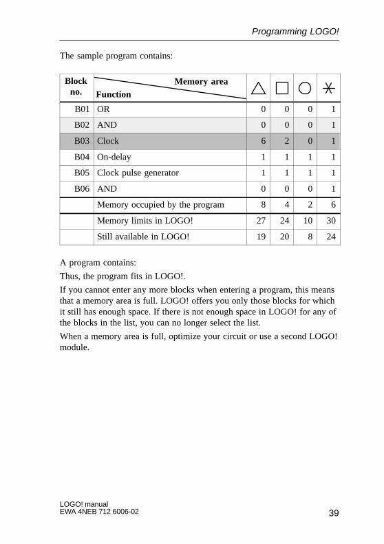
The sample program contains:
Blockno. Function
Memory area
B01 OR 0 0 0 1
B02 AND 0 0 0 1
B03 Clock 6 2 0 1
B04 On-delay 1 1 1 1
B05 Clock pulse generator 1 1 1 1
B06 AND 0 0 0 1
Memory occupied by the program 8 4 2 6
Memory limits in LOGO! 27 24 10 30
Still available in LOGO! 19 20 8 24
A program contains:
Thus, the program fits in LOGO!.
If you cannot enter any more blocks when entering a program, this meansthat a memory area is full. LOGO! offers you only those blocks for whichit still has enough space. If there is not enough space in LOGO! for any ofthe blocks in the list, you can no longer select the list.
When a memory area is full, optimize your circuit or use a second LOGO!module.
Programming LOGO!
LOGO! manualEWA 4NEB 712 6006-02
40
3.8 The golden rules for working with LOGO!
Rule 1
You enter the circuit in programming mode. You switch to programmingmode by pressing the 3 keys , and OK simultaneously.
You change the values of times and parameters in parameterization mode.You switch to parameterization mode by pressing the 2 keys ESC and OKsimultaneously.
Rule 2
You enter a circuit in the following sequence:From output to input
Rule 3
The following applies when entering a circuit:
� When the cursor appears in the form of an underscore, you can movethe cursor– Use the keys , , and to move the cursor in the circuit
– Press OK to select a connnector/block
– Press ESC to exit circuit input
� When the cursor appears in the form of a solid block, you select aconnector/block– Use the keys and to select a connector/block
– Press OK to accept a selection– Press ESC to go back one step
Rule 4
LOGO! can only store complete programs
Programming LOGO!
41LOGO! manualEWA 4NEB 712 6006-02
3.9 Overview of LOGO!’s menus
>Program.. PC/Card.. Start
>Edit Prg Clear Prg Set Clock
>PC�LOGO LOGO�Card Card�LOGO
Main menu Programming menu
PC/card menue
>Set Clock Set Param
OK
OK
ESC
ESC
Parameterization menu
Programming mode
Parameterization mode
Programming LOGO!
LOGO! manualEWA 4NEB 712 6006-02
42
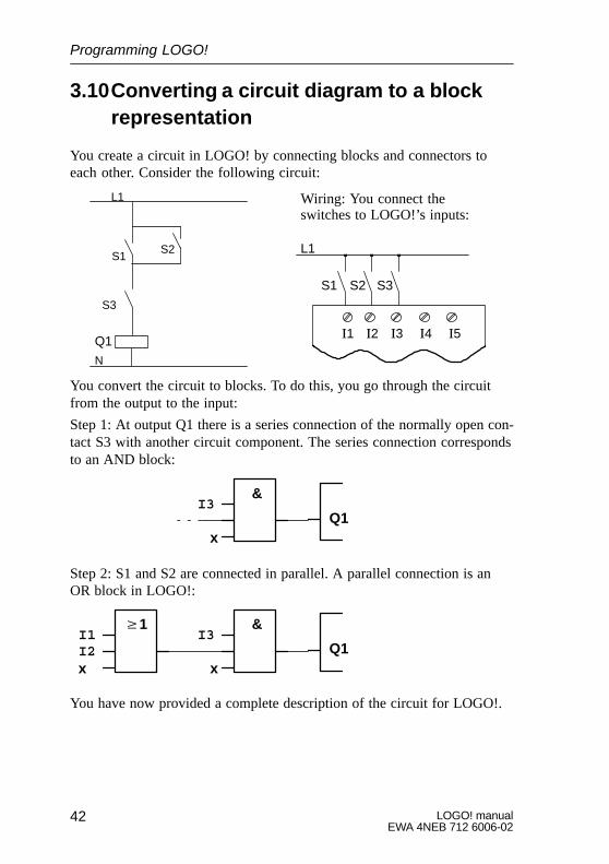
3.10Converting a circuit diagram to a blockrepresentation
You create a circuit in LOGO! by connecting blocks and connectors toeach other. Consider the following circuit:
L1
N
S1
Q1
S2
S3
Wiring: You connect theswitches to LOGO!’s inputs:
�1 �2 �3 �4 �5
L1
S1 S2 S3
You convert the circuit to blocks. To do this, you go through the circuitfrom the output to the input:
Step 1: At output Q1 there is a series connection of the normally open con-tact S3 with another circuit component. The series connection correspondsto an AND block:
I3
xQ1
&
Step 2: S1 and S2 are connected in parallel. A parallel connection is anOR block in LOGO!:
I3
xQ1
&�1I1I2x
You have now provided a complete description of the circuit for LOGO!.
Programming LOGO!
43LOGO! manualEWA 4NEB 712 6006-02
3.11 Entering a program
You have designed a circuit and now want to enter it in LOGO!. The ex-ample below illustrates how to do this.
3.11.1 Switching to programming mode
You have connected LOGO! to the mains and switched on the power. Thefollowing message appears on the display:
No Program
Switch LOGO! to programming mode. To do this, press the keys , andOK simultaneously.
No Program
The fact that you have to press the keys simultaneously prevents anyonepressing them and switching to programming mode inadvertently. Whenyou press the keys, LOGO!’s main menu appears:
>Program.. PC/Card.. Start
LOGO!’s main menu
On the left in the first line you will see a ”>”. You press the and keysto move the ”>” up and down. Move the ”>” to ”Program..”, and press theOK key. LOGO! switches to the programming menu:
Programming LOGO!
LOGO! manualEWA 4NEB 712 6006-02
44
>Edit Prg Clear Prg Set Clock
LOGO!’s programming menu
Here too, you can move the ”>” by pressing the and keys. Position the”>” on ”Edit Prg” (i.e. to enter the program), and press the OK key.LOGO! then shows you the first output:
LOGO!’s first output
Q1
You can use the and keys to select the other outputs. At this point, youbegin to enter your circuit.
3.11.2 First program
Let’s have a look at the following circuit: a parallel connection of twoswitches. In the circuit diagram, the circuit looks like this:
”Q1”
S1 ”Q1”S2
E1
The consumer is switched on byswitch S1 or switch S2. As far asLOGO! is concerned, the parallelconnection of the switches is an ORblock, because S1 or S2 switchesthe output on.
Translated into the LOGO! program, this means: Relay K1 (in LOGO!:Q1) is controlled by an OR block. I1 and I2 are connected to the input ofthe OR block, S1 to I1 and S2 to I2.Thus, the program in LOGO! looks like this:
I1
I2
xQ1
�1
Programming LOGO!
45LOGO! manualEWA 4NEB 712 6006-02
The wiring is as follows:
L1 N I1 I2 I3 I4 I5 I6
Q1 Q2 Q3 Q4
SIEMENS
L1
N
S1 S2
L
N
Switch S1 acts on input I2, and switch S2 acts on input I2. The consumeris connected to relay Q1.
3.11.3 Editing the program
Let’s enter the program now (from the output to the input). Initially,LOGO! displays the output:
LOGO!’s first output
Q1
The Q of Q1 is underlined. This underlining is the cursor. The cursor indi-cates your current position in the program. You can move the cursor bypressing the , , and keys. Now press the key. The cursor movesto the left.
Programming LOGO!
LOGO! manualEWA 4NEB 712 6006-02
46
The cursor indicates your positionin the program.
Q1
At this point, enter only the first block (the OR block). Press the OK keyto switch to input mode.
The cursor appears in the form ofa solid block: You can select aconnector or block.Q1Co
The cursor no longer appears in the form of an underline; instead, it ap-pears as a solid block that flashes on and off. At the same time, LOGO!offers you the first list for selection. Select the GF list (by pressing the key until GF appears), and press the OK key. LOGO! then displays thefirst block in the list of basic functions:
The first block in the list of basicfunctions is AND. The cursor ap-pears in the form of a solid block,indicating that you have to selecta block.
&B01
Q1
Press the or key until the OR block appears in the display:
�1The cursor is still in the block andappears in the form of a solidblock.
B01
Q1
Press the OK key, and conclude your entry.
Programming LOGO!
47LOGO! manualEWA 4NEB 712 6006-02
�1
The following appears in the display panel
B01
Q1
B01
�1
Q1
Your program looks like thisBlock number
You have now entered the first block. Every block you enter receives anumber, the block number. All you have to do now is wire the inputs ofthe block. To do this:
Press the OK button:
�1
The following appears in the display panel
B01
Q1
B01
�1
Q1
Your program looks like this
Co
Select the Co list: Press the OK key
�1
The following appears in the display panel
B01
Q1
B01
�1
Q1
Your program looks like this
x
The first item in the Co list is the character for indicating that an input isnot used, an ”x”. Use the or key to select input I1.
�1Q1
I1
Press the OK key: I1 is connected to the input of the OR block. The cursorjumps to the next input of the OR block.
Programming LOGO!
LOGO! manualEWA 4NEB 712 6006-02
48
�1
The following appears inthe display panel
B01
Q1
�1
Q1
Your program looks like this
I1I1
B01
–
Now connect input I2 to the input of the OR block. You know how to dothis already:1. Switch to input mode: OK 2. Select the Co list: or
3. Accept the Co list: OK 4. Select I2: or
5. Accept I2: OK
Thus, I2 is now connected to the input of the OR block:
�1
The following appears inthe display panel
B01
Q1
�1
Q1
Your program looks like this
I1I1
B01
I2
I2
We do not need the last input of the OR block in this program. In aLOGO! program, you mark an input that is not used with an ”x”, so enterthe ’x’ now (you know the principle already):
1. Switch to input mode: OK 2. Select the Co list: or
3. Accept the Co list: OK 4. Select x: or 5. Accept x: OK
Thus, all the block’s inputs are now wired. As far as LOGO! is concerned,the program is now complete. LOGO! returns to output Q1.
Programming LOGO!
49LOGO! manualEWA 4NEB 712 6006-02
The following appears in thedisplay panel
�1
Q1
Your program looks like this
I1
B01
I2Q1B01x
If you want to have another look at your first program, you can use the or key or the cursor to move through the program.
But we are going to exit program input now and switch LOGO! to RUN.To do this, proceed as follows:1. Return to the programming menu: ESC
If this does not return you to the programming menu, you have not wired ablock completely. LOGO! displays the point in the program at which youforgot something (LOGO! only accepts complete programs, which is verymuch in your interests). Read also page 57 on this.
2. Return to the main menu: ESC 3. Move ’>’ to ’Start’: or
4. Accept Start: OK
LOGO! switches to RUN. In RUN, LOGO! displays the following:
I:123456LOGO!’s display panel in RUN
State of the inputs
Current time in LOGO! (versionswith a clock only)
LOGO! is in RUN
State of the outputs
I:123456 Mo 09:00
Q:1234 RUN
What do we mean when we say ”LOGO! is in RUN?”
In RUN, LOGO! executes the program. It reads the states of the inputs,uses the program you have specified to determine the states of the outputs,and switches the relays at the outputs on or off.
Programming LOGO!
LOGO! manualEWA 4NEB 712 6006-02
50
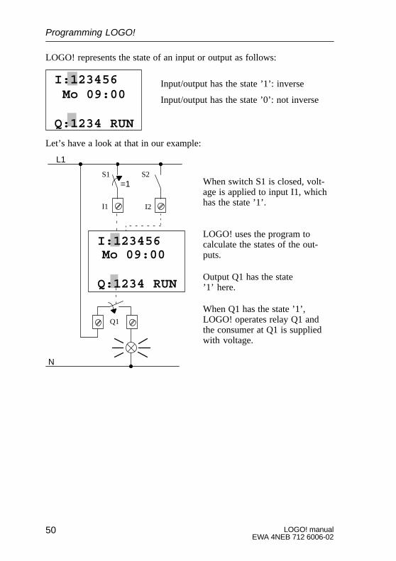
LOGO! represents the state of an input or output as follows:
Input/output has the state ’1’: inverse
Input/output has the state ’0’: not inverse
I:123456 Mo 09:00
Q:1234 RUN
Let’s have a look at that in our example:
When switch S1 is closed, volt-age is applied to input I1, whichhas the state ’1’.
LOGO! uses the program to calculate the states of the out-puts.
Output Q1 has the state ’1’ here.
When Q1 has the state ’1’, LOGO! operates relay Q1 andthe consumer at Q1 is suppliedwith voltage.
I:123456Mo 09:00
Q:1234 RUN
L1
N
S1 S2=1
I1 I2
Q1
Programming LOGO!
51LOGO! manualEWA 4NEB 712 6006-02
3.11.4 Second program
We use the second program to show you:� How to insert a block in an existing program
� How to select a block for a special function
� How to enter parameters
In order to produce the second program, we modify the first one.
Let’s begin by looking at the circuit diagram for the second program:
You know the first part of the cir-cuit already. Switches S1 and S2operate a relay. The relay switcheson consumer E1 and switches it offafter a delay of 12 minutes.
L1
N
S1 S2 K1
K1 E1
In LOGO!, the program looks like this:
�1
Q1
I1
I2
x x
T
This isthe newblock
You will recognize the OR block and the output relay Q1 from the firstprogram. Only the off-delay is new.
You modify your first program as follows:
Switch LOGO! to editing mode.
To do this, proceed as follows:1. Switch LOGO! to programming mode
(by pressing the , and OK keys simultaneously)
2. Select ”Program..” from the main menu (by moving ’>’ to ”Program..” and pressing the OK key)
3. Select ”Edit Prg” in the programming menu (by moving ’>’ to ”Edit Prg” and pressing the OK button)
You can now modify the existing program.
Programming LOGO!
LOGO! manualEWA 4NEB 712 6006-02
52
Inserting an additional block in a program
Move the cursor to the B of B01 (B01 is the block number of the ORblock).
Q1B01
Move the cursor:Press
At this point we insert the new block. Press the OK button:
Q1BN
LOGO! displays the BN list.
Select the SF list (� key).
Q1SF
The SF list contains the blocks for the special functions
Press the OK key.
The block of the first special function appears:
TrgT Q1
When you select a block for a specialor basic function, LOGO! displays theblock of the function. The cursor ispositioned in the block and itself ap-pears in the form of a solid block. Usethe � or � key to select the desiredblock.
Programming LOGO!
53LOGO! manualEWA 4NEB 712 6006-02
Select the desired block (off-delay, see next diagram), and press the OKkey:
R
The inserted block receives the block num-ber B02. Block B01, which has been con-nected up to now to Q1, is connected auto-matically to the uppermost input of the in-serted block. The cursor is positioned at theuppermost input of the inserted block.
B01
TQ1
B02
The off-delay block has 3 inputs. The uppermost input is the trigger input(Trg). You use this input to start the off-delay. In our example, the off-delay is started by the OR block B01. You reset the time and output bymeans of the reset input, and you set the time for the off-delay at T. Youreset the time and output by means of the reset input, and you set the timefor the off-delay by means of T parameter.
In our example, we do not use the reset input of the off-delay. We wire itwith ’x’. You learned how to do this in the first program, but just to re-mind you, here is the procedure again:
1. Position the cursor under the R: or
2. Switch to input mode: OK 3. Select the Co list: or
4. Accept the Co list: OK 5. Select ’x’: or 6. Accept ’x’: OK
The display should now look like this:
xB01
TQ1
B02
Now enter the time T for the off-delay:1. If the cursor is not yet under the T,
move it there: or
2. Switch to input mode: OK
Programming LOGO!
LOGO! manualEWA 4NEB 712 6006-02
54
LOGO! displays the parameter window for parameters:
B02: the parameter of block B02 T: is a time
The parameter is displayed in parame-terization mode and can be modifiedthere
B02:TT=00.00s+
Time value Time unit
The cursor appears on the first position of the time value.
To change the time value, proceed as follows:
Use the keys and to move the cursor to the different positions.Use the keys and to change the value.
If you have entered the time value, press the OK key.
Set the time to 12:00 minutes (T = 12:00):
1. Move the cursor to the first position: or 2. Select ’1’: or
3. Move the cursor to the second position: or
4. Select ’2’: or 5. Move the cursor to the unit: or
6. Select the unit m for minutes: or
Displaying/hiding a parameter
If you do not want the parameter to be displayed in parameterizationmode:
7. Move the cursor to the protection mode: or 8. Select the protection mode ’–’: or
You should now see the following on the display:
B02:TT=12:00m+
B02:TT=12:00m–or
9. Conclude your input: OK
Programming LOGO!
55LOGO! manualEWA 4NEB 712 6006-02
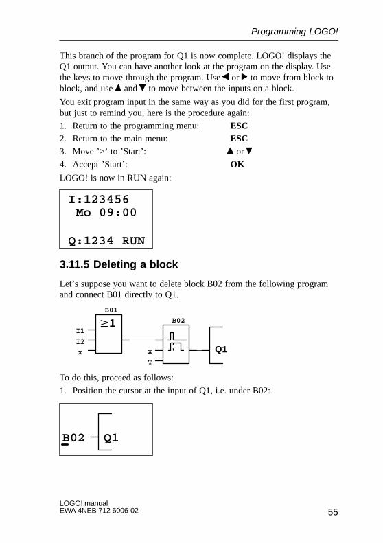
This branch of the program for Q1 is now complete. LOGO! displays theQ1 output. You can have another look at the program on the display. Usethe keys to move through the program. Use or to move from block toblock, and use and to move between the inputs on a block.
You exit program input in the same way as you did for the first program,but just to remind you, here is the procedure again:
1. Return to the programming menu: ESC2. Return to the main menu: ESC 3. Move ’>’ to ’Start’: or
4. Accept ’Start’: OK
LOGO! is now in RUN again:
I:123456
Q:1234 RUN
Mo 09:00
3.11.5 Deleting a block
Let’s suppose you want to delete block B02 from the following programand connect B01 directly to Q1.
Q1
I1
I2
x x
T
B01
B02
To do this, proceed as follows:
1. Position the cursor at the input of Q1, i.e. under B02:
B02 Q1
Programming LOGO!
LOGO! manualEWA 4NEB 712 6006-02
56
2. Press the OK key.3. Connect block B01 instead of block B02 directly to output Q01:
Select the BN list, and then press OK.Select B01, and then press OK.
Result: Block B02 is deleted. Block B01 is now connected directly to theoutput instead of block B01.
3.11.6 Deleting a number of interconnected blocks
Let’s suppose you want to delete blocks B01 and B02 from the followingprogram.
Q1
I1
I2
x x
T
B01
B02
To do this, proceed as follows:1. Position the cursor at the input of Q1, i.e. under B02:
B02 Q1
2. Press the OK key.3. Set the connector x instead of block B02 at the Q1 output:
Select the Co list, and then press OK.Select x, and then press OK.
Result: Block B02 is now deleted, and all blocks that are connected to itare deleted with it (i.e. block B01 in the example).
Programming LOGO!
57LOGO! manualEWA 4NEB 712 6006-02
3.11.7 Correcting typing errors
It is easy to correct typing errors in LOGO!:� If you have not yet concluded input, you can use ESC to go back a step
� If you have already concluded input, simply start again:
1. Move the cursor to the location of the error2. Switch to input mode: OK3. Enter the correct wiring for the input.
You can only replace one block with another if the new block has exactlythe same number of inputs as the old one. However, you can delete the oldblock and insert a new one. You can insert whichever block you like.
3.11.8 ”?” on the display
If you have entered a program and want to exit Edit Prg with ESC, LOGO!checks whether you have wired all the inputs of all the blocks correctly. Ifyou have forgotten an input, LOGO! displays the first place at which youhave forgotten something and marks with a question mark all those inputsthat have not been wired.
You have not yet wired theinput here
You have not yet specified avalue for the parameter
R ?B01
T ?Q1
B02
Wire the input, and enter a value for the parameter. You can then exit EditPrg by pressing the ESC key.
3.11.9 Deleting a program
To delete a program, proceed as follows:1. Switch LOGO! to programming mode:
, and OK simultaneously
Programming LOGO!
LOGO! manualEWA 4NEB 712 6006-02
58
>Program.. PC/Card.. Start
2. Move the ’>’ to ’Program..’ using the or key, and press OK
>Edit Prg Clear Prg Set Clock
LOGO! switches to the pro-gramming menu:
3. Move the ’>’ to ’Clear Prg’: or 4. Accept ’Clear Prg’: OK
Clear Prg>NoYes
To prevent you from inadvertentlydeleting your program, we haveincluded an additional query:
If you do not want to delete the program, leave the ’>’ on ’No’, and pressthe OK key.
If you are sure that you want to delete the program stored in LOGO!:5. Move the ’>’ to Yes: or
6. Press OK
Edit Prg>Clear Prg Set Clock
LOGO! deletes the pro-gram and then returns tothe programming menu:
Programming LOGO!
59LOGO! manualEWA 4NEB 712 6006-02
3.12Using the program module/card
You can copy the program stored in LOGO! to a program module/card.You can then insert the program module/card in a different LOGO! andcopy the program to it. You can use the program module/card to:
� Archive programs� Duplicate programs
� Send programs by post
� Write and test programs in the office and then transfer them to a differ-ent LOGO! in the cabinet
LOGO! is supplied with a cover. You receive the program module/cardseparately.
Programming LOGO!
LOGO! manualEWA 4NEB 712 6006-02
60
3.12.1 Removing the program module/card
You can change the program module/card when the power is on andLOGO! is in RUN or the programming mode. However, please heed thefollowing warning:
! Warning
Only use LOGO! 230 with the cover or the program module/card inserted.
Do not put your finger or an object made of metal or any otherconductive material in the open shaft of the program module/card.
The socket for the program module/card may be live if mis-takes have been made with the wiring (L1 and N mixed up).
The program module/card should only be changed by a trainedtechnician.
Remove the program module/card as follows:
RC
–004
7
Programming LOGO!
61LOGO! manualEWA 4NEB 712 6006-02
Carefully insert a screwdriver into the slot at the upper end of the programmodule/card, and ease the program module/card out of the shaft a little.You can now remove the program module/card.
Inserting the program module/card
The shaft for the program module/card is chamfered at the bottom on theright. The program module/card also has a chamfered edge. This preventsyou from inserting the program module/card the wrong way around. Insertthe program module/card into the shaft until it engages.
3.12.2 Copying a program from LOGO! to theprogram module/card
To copy a program to the program module/card, proceed as follows:1. Insert the program module/card
2. Switch LOGO! to programming mode: , and OK simultaneously
>Program.. PC/Card.. Start
3. Move the ’>’ to ”PC/Card”:
4. Press OK. The transfer menu appears
>PC�LOGO LOGO�Card Card�LOGO
5. Move the ’>’ to ’LOGO � Card’:
6. Press OK.
Programming LOGO!
LOGO! manualEWA 4NEB 712 6006-02
62
LOGO! copies the program to the program module/card. While it is doingthis, a ’#’ flashes on the display:
PC�LOGO>LOGO�Card Card�LOGO
#Flashes
When LOGO! has finished copying, it returns to the main menu:
Program..>PC/Card.. Start
The program is now also on the program module/card. You can remove theprogram module/card. Do not forget to replace the cover.
If there is a power failure while LOGO! is copying, you have to copy theprogram again once the power has been restored.
3.12.3 Copying a program from the program module/card to LOGO!
You have a program module/card containing your program. There are 2ways to copy the program to LOGO!:� Automatically when LOGO! starts up (power on)
� Via LOGO!’s PC/Card menu
Automatic copying at LOGO! startup
Proceed as follows:
1. Switch LOGO! into programming mode.2. Switch the power off.
3. Remove the cover from the shaft.
4. Insert the program module/card in the shaft.5. Switch the power on again.
Programming LOGO!
63LOGO! manualEWA 4NEB 712 6006-02
Result: LOGO! copies the program from the program module/card toLOGO!. While LOGO! is copying, a ’#’ flashes on the display. As soon asLOGO! has finished copying, LOGO! displays the main menu:
>Program.. PC/Card.. Start
Now you can switch LOGO! to RUN:
Note
Before you switch LOGO! to RUN, you must ensure that the system youare controlling with LOGO! does not represent a source of danger.
1. Move the ’>’ to Start: 2 �
2. Press OK
Using the PC/Card menu to copy
Read the note about changing the program module/card.
To copy a program from the program module/card to LOGO!, proceed asfollows:
1. Insert the program module/card2. Switch LOGO! to programming mode:
, and OK simultaneously
>Program.. PC/Card.. Start
3. Move the ’>’ to ”PC/Card”:
Programming LOGO!
LOGO! manualEWA 4NEB 712 6006-02
64
4. Press OK. The transfer menu appears:
PC�LOGO LOGO�Card>Card�LOGO
5. Move the ’>’ to ’Card � LOGO’: or
6. Press OK.
LOGO! copies the program from the progam module/card to LOGO!.When LOGO! has finished copying, it returns to the main menu:
Programming LOGO!
65LOGO! manualEWA 4NEB 712 6006-02
3.13Connecting LOGO! to a PC
To connect LOGO! to a PC, you need the LOGO! PC cable.
Remove the cover or the program module/card, and connect the cablethere.
Switch LOGO! to PC�LOGO mode
So that the PC can access LOGO!, LOGO! must be in PC � LOGO mode.To switch LOGO! to PC � LOGO mode:
1. Switch LOGO! to programming mode: , and OK simultaneously
2. Select ’PC/Card’: or
3. Press OK4. Select PC � LOGO: or 5. Press OK
LOGO! is now in PC � LOGO mode, and the following appears on thedisplay:
PC � LOGO
STOP:Press ESC
The PC can now access LOGO!.
To break the link to the PC, you press ESC.
Switching LOGO! to PC�LOGO mode at startup1. Switch the power off
2. Remove the cover or the program module/card, and connect the cablethere.
3. Switch the power on
LOGO! goes into PC � LOGO mode automatically
Programming LOGO!
LOGO! manualEWA 4NEB 712 6006-02
66
4 Parameterizing LOGO!By parameterization we mean setting the parameters of blocks. You canset delay times for time functions, switching times for clocks (timeswitches) and the threshold value of a counter.
You can set the parameters:
� In programming mode
� In parameterization mode
In parameterization mode, the programmer sets a value for a parameter.We introduced parameterization mode so that parameters can be changedwithout having to change the program. In this way, a caretaker can changetimes, for example, without having to change into programming mode.The advantage of this is that the program (and thus the circuit) is protectedbut can still be modified by the user of the circuit to suit requirements.
Note
LOGO! continues to execute the program in parameterization mode.
67LOGO! manualEWA 4NEB 712 6006-02
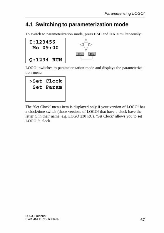
4.1 Switching to parameterization mode
To switch to parameterization mode, press ESC and OK simultaneously:
I:123456
Q:1234 RUN
Mo 09:00ESC OK
LOGO! switches to parameterization mode and displays the parameteriza-tion menu:
>Set Clock Set Param
The ’Set Clock’ menu item is displayed only if your version of LOGO! hasa clock/time switch (those versions of LOGO! that have a clock have theletter C in their name, e.g. LOGO 230 RC). ’Set Clock’ allows you to setLOGO!’s clock.
Parameterizing LOGO!
LOGO! manualEWA 4NEB 712 6006-02
68
4.1.1 Parameters
Parameters can be:� The delay times of a time relay
� The switching times (cams) of a clock
� The threshold value of a counter
How do you recognize a parameter? Simple: by its block number. Everyparameter is identified by the block number and the parameter abbrevi-ation. Examples:
B01:T
Block number Parameter abbreviation
B01:T A delay time can be set at block B01
B02:No1 Block B02 is a clock block. No1 is the first cam of this clock
B03:Par Block B03 is a counter. Par is the threshold value of the counter
4.1.2 Selecting a parameter
To select a parameter, proceed as follows:
1. Select the ’Set Param’ option from the parameterization menu
Set Clock>Set Param
2. Press OK
LOGO! displays the first parameter:
B01:T
Ta= 00:00m
T = 12:00mParameter
Value set for the parameter
Current time in LOGO!
Parameterizing LOGO!
69LOGO! manualEWA 4NEB 712 6006-02
If no parameter can be set, LOGO! displays the following:
Press ESCNo Param
No parameter can be changed:ESC returns you to the parametrizationmenu
3. Select the desired parameter: or
LOGO! displays a parameter in a separate window.
4. To change a parameter, select it and press the OK key.
4.1.3 Changing a parameter
To change a parameter, you first have to select it (see ”Selecting a parame-ter”).
You change the value of the parameter in the same way as you entered itin progamming mode:1. Move the cursor to the point at which you want to make the change:
or
2. Change the value: or 3. Accept the value: OK
Move: � or �
Change the value: � or � Finished: OK
B01:T
Ta= 00:00m
T = 01:00m
You cannot change the unit of the delay time for the parameter T in para-meterization mode. This is only possible in programming mode.
Parameterizing LOGO!
LOGO! manualEWA 4NEB 712 6006-02
70
Current value of a time T
If you view a time T in parameterization mode, it looks like this:
B01:T
Ta= 00:00m
T = 12:00m Time T set
Current time Ta
You can change the set time T (see ”Changing a parameter”).
Current value of the clock
If you view a cam of a clock in parameterization mode, it looks like this,for example:
B02:No1
Off=10:00
Day = SuThe switching state of the clock is displayed:
On =09:00
1
The clock is off (state ’0’ at theoutput)The clock is on (state ’1’ at theoutput)
1
0
LOGO! displays the switching state of the clock rather than the switchingstate of a cam. The switching state of the clock depends on all three cams(No1, No2 and No3).
Current value of a counter (Par)
If you view the parameter of a counter in parameterization mode, it lookslike this:
B03:Par
Cnt = 0028
Par = 0300 Switching threshold
Current count value
Parameterizing LOGO!
71LOGO! manualEWA 4NEB 712 6006-02
4.2 Setting the time (LOGO! 230 RC)
You can set the time:
� In parameterization mode
� In programming mode
Setting the time in parameterization mode:1. Switch to parameterization mode:
ESC and OK simultaneously2. Select ’Set Clock’, and press OK
Set ClockDay =_Mo
The cursor is positioned before the day ofthe week
Time=09:06
3. Select the day of the week: or
4. Move the cursor to the next position: or 5. Change the value at this position: or
6. Set the clock to the correct time. Repeat steps 4 and 5
7. Conclude your input: OK
Setting the time in programming mode:1. Switch to programming mode:
, and OK2. Select ’Program..’, and press OK3. Select (using or ) ’Set Clock’, and press OK
Now you can set the day of the week and the time, as described above (asof step 3).
Parameterizing LOGO!
LOGO! manualEWA 4NEB 712 6006-02
72
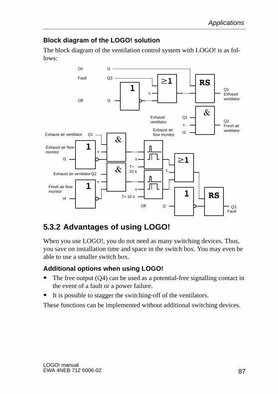
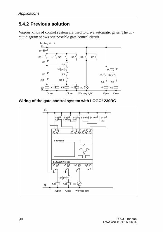
5 ApplicationsTo give you a feeling for the kind of situations in which you can useLOGO!, we have compiled a number of application examples. We have in-cluded the circuit diagram of the original solution for each example. For thesolutions using LOGO!, we have included the wiring and a diagram.
The LOGO! applications are available to our customers free of charge. Theexamples they contain are not binding and are included to provide generalinformation on how LOGO! can be used. Customer-specific solutions maybe different.
The user is responsible for ensuring that the system is run properly. Werefer you to the relevant national standards and system-related installationrequirements.
Errors are excepted the right to make changes reserved.
73LOGO! manualEWA 4NEB 712 6006-02
5.1Stairway, hall or corridor lighting
5.1.1 Demands on stairway lighting
The lighting system of a stairway should fulfill the following requirements:
� The light should be on when someone is on the stairway.
� If there is nobody on the stairway, the light should be off to save energy.
5.1.2 Previous solution
Previously there were 2 ways of switching the lighting:
� By means of an impulse relay
� By means of automatic stairway lighting
The wiring for these two lighting systems is the same.
When a pulse relay is used, the lighting system behaves as follows:
� When any switch is pressed: The lighting is switched on
� When any switch is pressed again: The lighting is switched off.
Disadvantage: People often forget to switch the light off again.
Lighting system with an automatic lighting device
When an automatic device is used, the lighting system behaves as follows:
� When any switch is pressed: The lighting is switched on.
� After a preset time has elapsed, the lighting is switched off automati-cally.
Disadvantage: The lighting cannot be switched on for an extended periodof time (e.g. for cleaning purposes). The switch for permanent lighting isusually on the automatic device, which is either impossible or difficult toaccess.
5.1.3 Lighting system with LOGO!
If you use LOGO!, you can replace the automatic lighting device or thepulse relay. You can implement both functions (time-dependent switching-off and pulse relay) using a single device. You can also include additionalfunctions without changing the wiring. Here are some examples:
� Impulse relay with LOGO!
� Automatic stairway lighting system with LOGO!
� LOGO! as a multi-function switching system with the following func-tions:
– Light on: Press switch (Light switches off after the set time elapses)
– Permanent light on: Press switch twice
– Light off: Press switch for 2 seconds
Applications
75LOGO! manualEWA 4NEB 712 6006-02
Wiring of the lighting system with LOGO! 230RC
ÏÏ
ÏÏÏÏ
Lights
Switches
L1 N I1 I2 I3 I4 I5 I6
Q1 Q2 Q3 Q4
SIEMENS
LN
PE
LOGO! 230RC
The external wiring of the lighting system with LOGO! is the same as for aconventional hall, corridor or stairway lighting system. The difference isthat the automatic lighting device or the pulse relay is replaced. Additionalfunctions are entered directly in LOGO!.
Pulse relay with LOGO!
I1Switch:Q1
Lightsx
In the event of a gate pulse at input I1, output Q1 switches over.
Automatic stairway lighting system with LOGO!
I1Switch:Q1
Lights
T06:00m
In the event of a gate pulse at input I1, output Q1 switches on and remainson for 6 minutes.
Applications
LOGO! manualEWA 4NEB 712 6006-02
76
Multi-functional switch with LOGO!
I1
�1
I1T
02.00s
T06:00m
Q1
x
I1
Switch light on
Switch permanentlight on
Switch light off
Off-delay
Latching relayPulse-relay
On-delay
Q1
The diagram shows the circuit for an input with an associated output.
This switch offers the following:
� When the switch is pressed: The light is switched on and goes offagain after the set time of 6 minutes (T=06:00m) has elapsed (off-delay)
� When the switch is pressed twice: The light is switched on perma-nently (the latching relay is set via the impulse relay).
� When the switch is pressed for 2 seconds: The light is switched off(on-delay switches the light off; both the permanent light and the normallight; this branch of the circuit is therefore used twice)
You can enter these circuits several times for the remaining inputs and out-puts. Instead of using 4 automatic stairway lighting systems or 4 impulserelays, you thus use only a single LOGO! module. However, you can alsouse the free inputs and outputs for completely different functions.
Applications
77LOGO! manualEWA 4NEB 712 6006-02
5.1.4 Special features and enhancement options
Features such as the following are available for adding functions or savingenergy:
� You can have the light flash before it goes off automatically.
� You can integrate various central functions:
– Central off
– Central on (panic button)
– Control of all lights or individual circuits by a daylight controlswitch
– Control by the integrated time switch (clock)(e.g. permanent light only until 24.00 hours; no enabling at certaintimes)
– Automatic switching off of permanent light after a preset time haselapsed (e.g. 3 hours)
Applications
LOGO! manualEWA 4NEB 712 6006-02
78
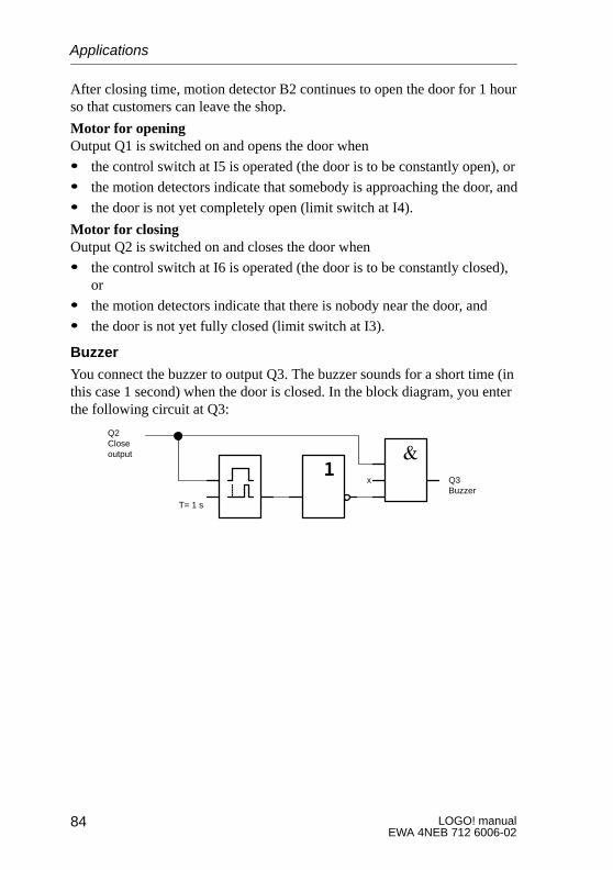
5.2 Automatic door
You often find automatic door control systems at the entrances to supermar-kets, public buildings, banks, hospitals, etc.
5.2.1 Demands on an automatic door
� When somebody approaches, the door must open automatically.
� The door must remain open until there is nobody in the doorway anymore.
� If there is nobody in the doorway anymore, it must close automaticallyafter a short time.
ÌÌÌÌÌÌÌÌÌÌÌÌ
ÑÑÑÑÑÑÑÑÑÑ
ÑÑÑÑÑÑÑÑÑÑÑÑÑÑÑÑÑÑÑÑÑÑÑÑÑÑÑÑÑÑÑÑ
ÌÌÌÌÌÌÌÌÌÌÌÌÌÌÌÌÌÌÌÌÌÌÌÌÌÌÌÌÌÌÌÌÌÌÌÌÌÌÌÌ
Motion detectorOutside
InsideMotion detector
B1
B2
Limit switchClosed
Limit switchOpen
Main switch
Q1
S1 S2
Motion detector
Main switch
The door is generally driven by a motor with a safety clutch. This preventspeople from being caught or injured in the door. The control system is con-nected to the mains via a main switch.
Applications
79LOGO! manualEWA 4NEB 712 6006-02
5.2.2 Previous solution
K1 K2
K2 K1
K3 K3
Open Close
S2 S1
K3
B1 B2 K3
K4
K4
B2
K3
B1
S2
Open door Waiting time
Auxiliary circuit
L1
N
As soon as one of the motion detectors B1 or B2 registers somebody’s pres-ence, the door is opened by K3.
If the two motion detectors detect nothing for a minimum period, K4 en-ables the close operation.
5.2.3 Door control system with LOGO!
LOGO! allows you to considerably simplify the circuit. You need only con-nect the motion detectors, the limit switches and the master contactors toLOGO!.
Applications
LOGO! manualEWA 4NEB 712 6006-02
80
Wiring of the door control system with LOGO! 230RC
L1 N I1 I2 I3 I4 I5 I6
Q1 Q2 Q3 Q4
SIEMENS
K1 K2
Open Close
B1 B2 S2S1
L1
N
LOGO! 230RC
Components used� K1 Master contactor Open
� K2 Master contactor Close
� S1 Limit switch Closed
� S2 Limit switch Open
� B1 Infrared motion detector Outside
� B2 Infrared motion detector Inside
Applications
81LOGO! manualEWA 4NEB 712 6006-02
Diagram of the door control system with LOGO! 230RC
& 1
1
1
&
I4
I3
Q2
Q1
RSI1I2
1I4
T=4s
Close
Openx
&
x
Q1
Q2
This is what the functional block diagram that corresponds to the circuitdiagram of the conventional solution looks like.
You can simplify this circuit if you make use of LOGO!’s functions. Youcan use the off-delay to replace the latching relay and on-delay. The follow-ing function block diagram illustrates this simplification:
& 1
1
1
&
I4
I3
I1
I2x
Q2
Q1
x10 s
Close
Open
Limit switchDoor open
Limit switchDoor open
Motion detector
Q1
Q2
Applications
LOGO! manualEWA 4NEB 712 6006-02
82
5.2.4 Special features and enhancement options
The functionality and user friendliness can be improved in the followingways, for example:
� You can connect an additional control switch: Open – Automatic –Closed (O-A-C)
� You can connect a buzzer to one of LOGO!’s outputs to indicate whenthe door is about to close.
� You can include time- and direction-dependent enabling of door opening(so that it only opens during shop opening hours and only from the in-side to the outside after closing time, for example).
5.2.5 Enhanced LOGO! 230 RC solution
Wiring of the enhanced LOGO! solution
L1 N I1 I2 I3 I4 I5 I6
Q1 Q2 Q3 Q4
SIEMENS
K1 K2
Open Close
B1 B2 S2S1
L1
N
Buzzer
S3 O-A-C
H1
LOGO! 230RC
Applications
83LOGO! manualEWA 4NEB 712 6006-02
Functional block diagram of the enhanced LOGO! solution
Detecting motionDuring business hours, motion detector B1 opens the door as soon as some-body wants to enter the shop from outside. Motion detector B2 opens thedoor if somebody wants to leave the shop.
Applications
LOGO! manualEWA 4NEB 712 6006-02
84
After closing time, motion detector B2 continues to open the door for 1 hourso that customers can leave the shop.
Motor for openingOutput Q1 is switched on and opens the door when
� the control switch at I5 is operated (the door is to be constantly open), or
� the motion detectors indicate that somebody is approaching the door, and
� the door is not yet completely open (limit switch at I4).
Motor for closingOutput Q2 is switched on and closes the door when
� the control switch at I6 is operated (the door is to be constantly closed),or
� the motion detectors indicate that there is nobody near the door, and
� the door is not yet fully closed (limit switch at I3).
Buzzer
You connect the buzzer to output Q3. The buzzer sounds for a short time (inthis case 1 second) when the door is closed. In the block diagram, you enterthe following circuit at Q3:
T= 1 s
x Q3Buzzer
Q2Closeoutput
Applications
85LOGO! manualEWA 4NEB 712 6006-02
5.3 Ventilation system
5.3.1 Demands on a ventilation system
A ventilation system is used either to feed fresh air into a room or to removeused air from it. Consider the following example:
� The room contains an exhaust ventilator and a fresh air ventilator.
� Both ventilators are controlled by a control monitor.
� At no time must excess pressure develop in the room.
� The fresh air ventilator cannot be switched on unless the flow monitorindicates that the exhaust ventilator is functioning properly.
� A warning light comes on in the event of a ventilator failing.
The circuit diagram for the previous solution is as follows:
K1 K5
K5
S1
Exhaust air Fresh air
S0
K3K2
Operation
Auxiliary circuitL1
N
S2
K1
v>
S2
H1K4
S3v>
K5
Fault
H2
K2 K4
Applications
LOGO! manualEWA 4NEB 712 6006-02
86
The ventilators are controlled by flow monitors. If no air flow is detectedafter a short waiting time has elapsed, the system is switched off and a faultis reported. You acknowledge this by pressing the stop switch.
In addition to the flow monitors, the ventilation monitoring system requiresan evaluation circuit with a number of switching devices. The evaluationcircuit can be replaced by a single LOGO! module.
Wiring of the ventilation system with LOGO! 230RC
L1N I1 I2 I3 I4 I5 I6
Q1 Q2 Q3 Q4
SIEMENS
K1 K2
S1
L1
N
S2 S3 v>v>
H1 H2
S0
LOGO! 230RC
Exhaust ventilator Fresh air ventilator
Components used� K1 Master contactor
� K2 Master contactor
� S0 Stop switch
� S1 Start switch
� S2 Flow monitor
� S3 Flow monitor
� H1 Warning light
� H2 Warning light
Applications
87LOGO! manualEWA 4NEB 712 6006-02
Block diagram of the LOGO! solution
The block diagram of the ventilation control system with LOGO! is as fol-lows:
x
I1On
Q3Fault
I2Off
Q1Exhaustventilator
Q2Fresh airventilator
Q1Exhaustventilator
I3Exhaust airflow monitor
x
I2OffFault
x
T=10 s
x
T= 10 s
x
x
x
I3
Exhaust air flowmonitor
I4
Fresh air flowmonitor
Exhaust air ventilator Q1
Exhaust air ventilatorQ2
Q3
5.3.2 Advantages of using LOGO!
When you use LOGO!, you do not need as many switching devices. Thus,you save on installation time and space in the switch box. You may even beable to use a smaller switch box.
Additional options when using LOGO!� The free output (Q4) can be used as a potential-free signalling contact in
the event of a fault or a power failure.
� It is possible to stagger the switching-off of the ventilators.
These functions can be implemented without additional switching devices.
Applications
LOGO! manualEWA 4NEB 712 6006-02
88
Functional diagram of the enhanced LOGO! solution
The ventilators at Q1 and Q2 are switched off as shown in the followingcircuit:
x
T=10 s
T=30 s
Q1Exhaustairventilator
Q2Fresh airventilator
On I1
I2
Off
Fault Q3
x
x
I3Exhaust air flowmonitor
I2OffFault
T=10 s
T=10 s
x
x
x
I3
Exhaust air flowmonitor
I4
Fresh air flowmonitor
Exhaust air ventilator Q1
Exhaust air ventilatorQ2
Q3
You can also generate a message via output Q4:
Q3Fault
Q4Message
The contacts of output Q4 are always closed when the system is running.Relay Q4 does not release unless there is a power failure or a fault in thesystem. This contact can be used for teleindication, for example.
Applications
89LOGO! manualEWA 4NEB 712 6006-02
5.4 Industrial gate
ÔÔÔÔÔÔÔÔÔÔÔÔÔÔÔÔ
ÔÔÔÔÔÔÔÔÔÔÔÔÔÔÔÔ
WarninglightSafety pressure bar
There is often a gate at the entrance to a company’s premises. This is onlyopened to let vehicles in and out.
The gate is controlled by the gateman.
5.4.1 Demands on the door control system
� The gate is opened, closed and monitored by the gateman, who operatesit by means of a switch in the gatehouse.
� The gate is normally completely open or completely closed, but itsmovement can be interrupted at any time.
� A warning light starts flashing on and off 5 seconds before the gate be-gins to move and continues for as long as the gate is still moving.
� A safety pressure bar ensures that nobody gets injured and nothing getscaught or damaged when the gate closes.
Applications
LOGO! manualEWA 4NEB 712 6006-02
90
5.4.2 Previous solution
Various kinds of control system are used to drive automatic gates. The cir-cuit diagram shows one possible gate control circuit.
K1 K5
K3
S1
Open Close
S0
K3K2
Warning light
Auxiliary circuitL1
N
K1
H1K4
S5 p>
K6
K6
K1
S2
S2 K3
K2 K4
Open Close
K5
S5 p>
S1
K3 K1
S4S3
Wiring of the gate control system with LOGO! 230RC
L1 N I1 I2 I3 I4 I5 I6
Q1 Q2 Q3 Q4
SIEMENS
K1 K2
Open Close
S4S3
L1
N
S1 S2 S0
S5
p>
S5 p>
Warning light
H1
Open Closed Stop
LOGO! 230RC
Applications
91LOGO! manualEWA 4NEB 712 6006-02
Components used� K1 Master contactor
� K2 Master contactor
� S0 Stop switch
� S1 Open switch
� S2 Close switch
� S3 Open position switch
� S4 Closed position switch
� S5 Safety pressure bar
Functional diagram of the LOGO! solution
T=5 s
T=5 s
x
x
x
x
Q1Open
Q3Flashinglight
Q1Close
I3
I4
I3
I6
I5
I1
I2
Q2
Q1
Safety bar
Gate is closed
Gate is open
Stop switch
Open startswitch
Stop switch
Close startswitch
The open and close start switches start the movement of the gate, providedthe gate is not currently moving in the opposite direction. The gate stopsmoving when the stop switch is pressed or when it reaches a limit switch.The gate is also prevented from closing by the safety bar.
Applications
LOGO! manualEWA 4NEB 712 6006-02
92
5.4.3 Enhanced LOGO! solution
In our enhanced solution, the gate will automatically open again when thesafety bar operates.
When lighting systems are planned in companies, the type and number oflamps used depends on the level of lighting required. For reasons of costefficiency, fluorescent lamps arranged in rows of tubes are often used. Theyare subdivided into switching groups according to how the room is used.
5.5.1 Demands on the lighting system
� The lamps are switched on and off locally.
� If there is sufficient natural light, the lamps on the window side of theroom are automatically switched off by means of a brightness-sensitiveswitch.
� The lights are switched off automatically at 8 o’clock in the evening.
� It must be possible at all times to switch the lights on and off locally.
Applications
LOGO! manualEWA 4NEB 712 6006-02
94
5.5.2 Previous solution
B1
L1
N
E1
E1
lx> K6
E5
K5
E4
K4
E3
K3
E2K3 K4 K5 K6
S1 S2 S3 S4
K1 K2
K4K4K4
The lights are operated by means of a pulse relay controlled by the switchesat the door. Independently of this, they are reset by the time switch (clock)or by the brightness-sensitive switch via the central off input. The switch-ing-off commands must be cut by impulse relays so that it is still possible toswitch the lights on and off locally after they have been switched off cen-trally.
Components required:
� Switches S1 to S4
� Daylight control switch B1
� Time switch (clock) E1
� Impulse relays K1 and K2
� Remote-control switches with central off K3 to K6
Disadvantages of the previous solution� To implement the required functions, a large amount of circuitry is re-
quired.
� The large number of mechanical components means that considerablewear and high maintenance costs can be expected.
� Functional changes are costly to implement.
Applications
95LOGO! manualEWA 4NEB 712 6006-02
5.5.3 Fluorescent lamp control with LOGO! 230RC
L1 N I1 I2 I3 I4 I5 I6
Q1 Q2 Q3 Q4
SIEMENS
L1
NE2 E3 E4
B1
lx<
Fluorescentlamp 1
E5
Fluorescentlamp 2
Fluorescentlamp 3
Fluorescentlamp 4
S1 S2 S3 S4
LOGO! 230RC
Components used� S1 to S4 Switches
� B1 Daylight control switch
Applications
LOGO! manualEWA 4NEB 712 6006-02
96
Functional diagram of the LOGO! solution
x
T=1s
Q2
Mo..Su20:00 – 20.01
Mo..Su21:00 – 21.01
Switch-off pulse generated by time switch (clock)
I5
T=1s
Daylightcontrol switch
x
I5
Switch-off pulse generated by daylight control switch
I1
I2
I3
I4
x
x
Q1
Q4
Q3
Lamp 3Corridor side
Lamp 4Corridor side
Lamp 1Window side
Lamp 2Window side
Advantages of the LOGO! solution� You can connect the lamps to LOGO! directly provided the switching
capacity of the outputs is not exceeded. In the case of greater capacities,you should use a power contactor.
� You connect the brightness-sensitive switch to one of LOGO!’s inputsdirectly.
� You do not need a time switch; this function is integrated in LOGO!.
� The fact that fewer switching devices are required means you can installa smaller sub-distribution unit and thus save space.
� Fewer devices are required.
� The lighting system can be easily modified.
� Additional switching times can be set as required (staggered switch-offpulses at the end of the day).
� The effect of the brightness-sensitive switch can easily be applied to alllamps or a changed group of lamps.
Applications
97LOGO! manualEWA 4NEB 712 6006-02
5.6 Rainwater pump
Rainwater is being used increasingly in homes in addition to drinking water.This saves money and is environment-friendly. You can use rainwater, forexample, for:
� Washing clothes
� Watering the garden
� Watering house plants
� Washing the car
� Flushing the toilet
The following drawing illustrates how a system for using rainwater works:
ÕÕÕÕÕÕÕÕÕ
ŠŠŠŠŠŠ
ÎÎÎÎÎÎÎÎÎÎÎÎÎÎÎ
Pump
S1
ÕÕÕÕÕÕÕÕÕ
S2
S3
S4
M1
K4Rainwatersupply
Rainwatercollecting tank
Pressure tank
Rainwater pipe
Control indistributionbox
Pressure switchDrinking water supply
Run-dry protection on
Drinking water supply onRun-dry protection off
Drinking water supply off
The rainwater is caught in a collecting tank, from which it is pumped into apipe system. The rainwater can then be taken from this in the same way thatdrinking water can. If the tank should ever run dry, it can be supplied withdrinking water.
Applications
LOGO! manualEWA 4NEB 712 6006-02
98
5.6.1 Demands on the control system for a rainwaterpump
� The water must be available at all times. Whenever necessary, the con-troller must switch automatically to drinking water.
� When the switch to drinking water takes place, no rainwater must getinto the drinking water system.
� If there is not enough water in the rainwater tank, the pump cannot beswitched on (run-dry protection).
5.6.2 Previous solution
K1 K2
K3
S1
K3
S4 K3
Auxiliary circuitL1
NK4
S3 K4p<K2
S3 S2
Y1
Pump After-run time
Run-dryprotection
Pure watersupply
The pump and a solenoid valve are controlled by a pressure switch and 3float switches in the rainwater tank. The pump must be switched on whenthe pressure goes below the minimum permitted. Once the operating pres-sure is reached, the pump is switched off again after an after-run time of afew seconds. The after-run time prevents the water pump from constantlybeing switched on and off if the water is drawn for any length of time.
Applications
99LOGO! manualEWA 4NEB 712 6006-02
5.6.3 Rainwater pump with LOGO! 230RC
L1 N I1 I2 I3 I4 I5 I6
Q1 Q2 Q3 Q4
SIEMENS
K1 Y1
S4S3
L1
N
S1 S2p<
LOGO! 230RC
Pump Drinking water supply
Apart from LOGO!, you need only the pressure switch and the floatswitches to control the pump. If you are using a three-phase motor, you needa master contactor. If the system has a single-phase motor, you need a con-tactor if the motor requires more current than output relay Q1 can switch.The consumption of a solenoid valve is so low that you can normally con-trol it directly.
� K1 Master contactor
� Y1 Solenoid valve
� S1 Pressure switch
� S2 to S4 Float switches
Applications
LOGO! manualEWA 4NEB 712 6006-02
100
Functional diagram of the LOGO! solution
I2Float switch for
drinking watersupply off
Drinking watersupply
Q2Float switch fordrinking watersupply on
I1Pressureswitch
I2Float switch forrun-dry protection off
I4Float switch forrun-dry protection on
x
T = 20 s x
PumpQ1
I2
5.6.4 Special features and enhancement options
In the functional diagram you can see how to wire the control system for thepump and the solenoid valve. Its structure corresponds to that of the circuitdiagram. However, you can also integrate additional functions for specificapplications that, with conventional technology, would require additionalequipment:
� Enabling of the pump at specific times
� Indication of an imminent or existing water shortage
� Indication of malfunctioning
Applications
101LOGO! manualEWA 4NEB 712 6006-02
5.7 Dereeler
A metal strip (coil) is fed to a punching device over a dereeler.
5.7.1 Demands on a dereeler
The following demands are placed on a dereeler:
� The metal strip must not sag.
� The metal fed to the punching device must not exceed a defined maxi-mum tension.
� If the metal strip becomes too taut, the punching device must beswitched off.
M~
Punching device
Metal strip
Switch S3Strip too taut � Punching device off
Switch S4Strip taut � Dereeler on
Switch S5Strip loose � Dereeler off
5.7.2 Previous solution
K1 Dereelerdrive
K2
K4
K3
S2 S3
K2
K2 K3
S4
K2 punchingdevice
H1
K1
S1
K4
S5
Enable
Automatic Strip taut Strip loose
The key-operated switch S1 is the operating mode switch (manual/auto-matic) for the dereeler. You can use switch S2 to control the motor of thedereeler manually. Switches S4 and S5 monitor the tension of the strip andswitch the motor of the dereeler on and off. Switch S3 switches the punch-ing device off when the strip is too taut.
Applications
LOGO! manualEWA 4NEB 712 6006-02
102
5.7.3 Dereeler with LOGO! 24R
If you use LOGO!, you can make the circuit much simpler. You only have toconnect the switches, the indicator light and the main contactor to LOGO!.
The block diagram for controlling the dereeler with LOGO! is as follows:
I2
I4
I5 R
I1
I3
x
x
I6
I2
I4
x
S
Manual mode onManual dereeler control Dereeler drive on
Automatic mode onPunching device off
Strip taut
Strip loose
Indicator light forautomatic mode
Enable punchingdevice
Automatic mode onPunching device off
Q1
Q2
Q3
5.7.4 Advantages of the LOGO! solution
If you use LOGO!, you need fewer switching devices less wiring is in-volved. You also save on assembly time and space in the switch box. Youmay even be able to use a smaller switch box.
Applications
LOGO! manualEWA 4NEB 712 6006-02
104
5.8 Additional application options
It is worth using LOGO! particularly when you:
� Can replace a number of auxiliary switching devices with the integratedfunctions of LOGO!.
� Want to save yourself wiring and installation work (because the wiring isdone in LOGO!).
� Want to reduce the space required by the components in the control cabi-net/distribution box. You may be able to use a smaller control cabinet/distribution box.
� Can add or change functions subsequently without having to install anadditional switching device or change the wiring.
� Have to provide your customers with additional functions for their do-mestic or building installation. Here are some examples:
– Home security: You can program LOGO! to switch a lamp on regu-larly or open and close your shutters while you are on holiday.
– Heating system: You can program LOGO! to run the circulationpump only when water or heat is really required.
– Cooling systems: You can program LOGO! to thaw your coolingsystems automatically on a regular basis to save energy costs.
– You can illuminate aquaria and terraria automatically on a time-de-pendent basis.
You can also:
� Use commercially available switches and buttons, which makes it easyto integrate in the installation.
� Connect LOGO! directly to your domestic installation due to its inte-grated power supply.
Do you have any suggestions?
There are many more potential applications for LOGO!. If you know of one,why not write to us? We will collect all the suggestions we receive, and weintend to pass on as many as we can. So drop us a line – no matter how un-usual or simple your LOGO! circuit is! We will be delighted to receive allyour suggestions.Write to:Siemens AGAUT V16 – LOGO!Gleiwitzer Straße 555D-90327 Nuremberg
Applications
105LOGO! manualEWA 4NEB 712 6006-02
6 Technical data
General technical data
Criterion Complies with Values
Dimensions W×H×D in mm
Weight
72 x 90 x 55with installation mechanism:72 x 90 x 59
approx. 190 g
Installation on 35 mm DIN rail Width of 4 modules
Ambient climatic conditions
Ambient temperature Cold: IEC 68-2-1
�Horizontal installation
Vertical installation
Heat:
IEC 68-2-2*
0 to 55 ��C
0 to 55 ��C
Storage/transport �40 ��C to + 70 ��C
Relative humidity IEC 68-2-30 From 5 to 95% no condensation
Short circuit-proof cos 1ÁÁÁÁÁÁÁÁÁÁÁÁÁÁÁÁÁÁÁÁÁÁÁÁÁÁÁ
Power protection B16600 A
ÁÁÁÁÁÁÁÁÁÁÁÁÁÁÁÁÁÁÁÁÁÁÁÁÁÁÁÁÁÁÁÁÁÁÁÁÁÁÁ
Short circuit-proofcos 0.5 to 0.7
ÁÁÁÁÁÁÁÁÁÁÁÁÁÁÁÁÁÁÁÁÁÁÁÁÁÁÁ
Power protection B16900 A
ÁÁÁÁÁÁÁÁÁÁÁÁÁÁÁÁÁÁÁÁÁÁÁÁÁÁ
Parallel switching of outputs to increase power ÁÁÁÁÁÁÁÁÁÁÁÁÁÁÁÁÁÁ
Not permitted
ÁÁÁÁÁÁÁÁÁÁÁÁÁÁÁÁÁÁÁÁÁÁÁÁÁÁÁÁÁÁÁÁÁÁÁÁÁÁÁ
Protection of output relay ÁÁÁÁÁÁÁÁÁÁÁÁÁÁÁÁÁÁÁÁÁÁÁÁÁÁÁ
Maximum 16 A,Characteristic B16
ÁÁÁÁÁÁÁÁÁÁÁÁÁÁÁÁÁÁÁÁÁÁÁÁÁÁ
Switching rate ÁÁÁÁÁÁÁÁÁÁÁÁÁÁÁÁÁÁÁÁÁÁÁÁÁÁÁÁÁÁÁ
ÁÁÁÁÁÁÁÁÁÁÁÁÁMechanical ÁÁÁÁÁÁÁÁÁ
ÁÁÁÁÁÁÁÁÁ10 Hz
ÁÁÁÁÁÁÁÁÁÁÁÁÁÁÁÁÁÁÁÁÁÁÁÁÁÁ
ohm load/lamp load ÁÁÁÁÁÁÁÁÁÁÁÁÁÁÁÁÁÁ
2 Hz
ÁÁÁÁÁÁÁÁÁÁÁÁÁÁÁÁÁÁÁÁÁÁÁÁÁÁ
Inductive load ÁÁÁÁÁÁÁÁÁÁÁÁÁÁÁÁÁÁ
0.5 Hz
Technical data
111LOGO! manualEWA 4NEB 712 6006-02
Switching capacity and service life of the relay outputs
Switching cycles / million
Switched current / A
0.1
0.2
0.3
0.4
0.5
1 2 3 4 5 6 7 8
DC 24V / max. 8 A
AC 115/120 V / max. 8 A
AC 230/240 V / max. 8 A
Figure 1 Switching capacity and service life of the contacts at ohm load (heating)
Switching cycles / million
Switched current / A
0.2
0.4
0.6
0.8
1.0
0.5 1 2
DC 24V / max. 2 A
AC 115/120 V / max. 2 A
AC 230/240 V / max. 2 A0.1
Figure 2 Switching capacity and service life of the contacts at highly inductiveload in accordance with IEC 947-5-1 DC13/AC15 (contactors, solenoidcoils, motors)
Technical data
LOGO! manualEWA 4NEB 712 6006-02
112
AbbreviationsB01 Block number B01
BN Block number
Cnt Count (input for counter)
Co Connector
Dir Direction (for counter: up or down)
En Enable (switching on the clock pulse generator)
GF Grundfunktion (basic function)
No Nocke (cam for clock)
Par Parameter for counter
R Reset
S Set (setting the latching relay)
SF Special function
T Time (parameter)
Ta Current value of a time (the current value of a time is displayed inthe parameterization mode)