Long-haul coherent communications using microresonator-based frequency combs ATTILA FÜLÖP,1,* MIKAEL MAZUR,1 ABEL LORENCES-RIESGO,1 TOBIAS A. ERIKSSON,1,4 PEI-HSUN WANG,2 YI XUAN,2,3 DAN. E. LEAIRD,2 MINGHAO QI,2,3 PETER A. ANDREKSON,1 ANDREW M. WEINER,2,3 AND VICTOR TORRES-COMPANY1 1Photonics Laboratory, Department of Microtechnology and Nanoscience, Chalmers University of Technology, SE-41296 Göteborg, Sweden 2School of Electrical and Computer Engineering, Purdue University, West Lafayette, IN 47907-2035, USA 3Birck Nanotechnology Center, Purdue University, West Lafayette, IN 47907-2035, USA 4Now at Nokia Bell Labs, Stuttgart, Germany *[email protected]
References and links 1. T. Udem, J. Reichert, R. Holzwarth, and T. W. Hänsch, “Absolute Optical Frequency Measurement of the
Cesium D1 Line with a Mode-Locked Laser,” Phys. Rev. Lett. 82(18), 3568–3571 (1999).2. D. J. Jones, S. A. Diddams, J. K. Ranka, A. Stentz, R. S. Windeler, J. L. Hall, and S. T. Cundiff, “Carrier-
envelope phase control of femtosecond mode-locked lasers and direct optical frequency synthesis,” Science 288(5466), 635–640 (2000).
3. N. R. Newbury, “Searching for applications with a fine-tooth comb,” Nat. Photonics 5(4), 186–188 (2011). 4. P. Del’Haye, A. Schliesser, O. Arcizet, T. Wilken, R. Holzwarth, and T. J. Kippenberg, “Optical frequency comb
generation from a monolithic microresonator,” Nature 450(7173), 1214–1217 (2007).5. T. J. Kippenberg, R. Holzwarth, and S. A. Diddams, “Microresonator-based optical frequency combs,” Science
332(6029), 555–559 (2011).6. J. S. Levy, A. Gondarenko, M. a. Foster, A. C. Turner-Foster, A. L. Gaeta, and M. Lipson, “CMOS-compatible
multiple-wavelength oscillator for on-chip optical interconnects,” Nat. Photonics 4(1), 37–40 (2010).7. J. Li, H. Lee, T. Chen, and K. J. Vahala, “Low-pump-power, low-phase-noise, and microwave to millimeter-
wave repetition rate operation in microcombs,” Phys. Rev. Lett. 109(23), 233901 (2012).8. A. Kordts, M. H. P. Pfeiffer, H. Guo, V. Brasch, and T. J. Kippenberg, “Higher order mode suppression in high-
Q anomalous dispersion SiN microresonators for temporal dissipative Kerr soliton formation,” Opt. Lett. 41(3),452–455 (2016).
9. H. Jung, C. Xiong, K. Y. Fong, X. Zhang, and H. X. Tang, “Optical frequency comb generation from aluminum nitride microring resonator,” Opt. Lett. 38(15), 2810–2813 (2013).
10. M. Pu, L. Ottaviano, E. Semenova, and K. Yvind, “Efficient frequency comb generation in AlGaAs-on-insulator,” Optica 3(8), 823–826 (2016).
11. Y. Xuan, Y. Liu, L. T. Varghese, A. J. Metcalf, X. Xue, P.-H. Wang, K. Han, J. A. Jaramillo-Villegas, A. AlNoman, C. Wang, S. Kim, M. Teng, Y. J. Lee, B. Niu, L. Fan, J. Wang, D. E. Leaird, A. M. Weiner, and M. Qi, “High-Q silicon nitride microresonators exhibiting low-power frequency comb initiation,” Optica 3(11), 1171–1180 (2016).
12. P. Del’Haye, A. Coillet, T. Fortier, K. Beha, D. C. Cole, K. Y. Yang, H. Lee, K. J. Vahala, S. B. Papp, and S. A.Diddams, “Phase-coherent microwave-to-optical link with a self-referenced microcomb,” Nat. Photonics 10(8), 516–520 (2016).
13. V. Brasch, E. Lucas, J. D. Jost, M. Geiselmann, and T. J. Kippenberg, “Self-referenced photonic chip solitonKerr frequency comb,” Light Sci. Appl. 6(1), e16202 (2016).
14. S. B. Papp, K. Beha, P. Del’Haye, F. Quinlan, H. Lee, K. J. Vahala, S. a. Diddams, P. Del’Haye, F. Quinlan, H. Lee, K. J. Vahala, and S. a. Diddams, “Microresonator frequency comb optical clock,” Optica 1(1), 10–14(2014).
15. X. Xue, Y. Xuan, H. J. Kim, J. Wang, D. E. Leaird, M. Qi, and A. M. Weiner, “Programmable single-bandpassphotonic rf filter based on kerr comb from a microring,” J. Lightwave Technol. 32(20), 3557–3565 (2014).
16. W. Liang, D. Eliyahu, V. S. Ilchenko, A. A. Savchenkov, A. B. Matsko, D. Seidel, and L. Maleki, “High spectral purity Kerr frequency comb radio frequency photonic oscillator,” Nat. Commun. 6, 7957 (2015).
17. M.-G. Suh, Q.-F. Yang, K. Y. Yang, X. Yi, and K. J. Vahala, “Microresonator soliton dual-comb spectroscopy,” Science 354(6312), 600–603 (2016).
18. A. Dutt, C. Joshi, X. Ji, J. Cardenas, Y. Okawachi, K. Luke, A. L. Gaeta, and M. Lipson, “On-chip dual combsource for spectroscopy,” ArXiv 1611.07673 (2016).
19. F. Ferdous, H. Miao, D. E. Leaird, K. Srinivasan, J. Wang, L. Chen, L. T. Varghese, and A. M. Weiner, “Spectral line-by-line pulse shaping of on-chip microresonator frequency combs,” Nat. Photonics 5(12), 770–776 (2011).
20. J. Pfeifle, V. Brasch, M. Lauermann, Y. Yu, D. Wegner, T. Herr, K. Hartinger, P. Schindler, J. Li, D. Hillerkuss, R. Schmogrow, C. Weimann, R. Holzwarth, W. Freude, J. Leuthold, T. J. Kippenberg, and C. Koos, “Coherent terabit communications with microresonator Kerr frequency combs,” Nat. Photonics 8(5), 375–380 (2014).
21. T. Ohara, H. Takara, T. Yamamoto, H. Masuda, T. Morioka, M. Abe, and H. Takahashi, “Over-1000-channel ultradense WDM transmission with supercontinuum multicarrier source,” J. Lightwave Technol. 24(6), 2311–2317 (2006).
22. D. Hillerkuss, R. Schmogrow, M. Meyer, S. Wolf, M. Jordan, P. Kleinow, N. Lindenmann, P. C. Schindler, A.Melikyan, X. Yang, S. Ben-Ezra, B. Nebendahl, M. Dreschmann, J. Meyer, F. Parmigiani, P. Petropoulos, B. Resan, A. Oehler, K. Weingarten, L. Altenhain, T. Ellermeyer, M. Moeller, M. Huebner, J. Becker, C. Koos, W.Freude, and J. Leuthold, “Single-Laser 32.5 Tbit/s Nyquist WDM Transmission,” J. Opt. Commun. Netw. 4(10), 715–723 (2012).
23. A. H. Gnauck, B. P. P. Kuo, E. Myslivets, R. M. Jopson, M. Dinu, J. E. Simsarian, P. J. Winzer, and S. Radic,“Comb-Based 16-QAM Transmitter Spanning the C and L Bands,” IEEE Photonics Technol. Lett. 26(8), 821–824 (2014).
24. A. Lorences-Riesgo, T. A. Eriksson, A. Fülöp, P. A. Andrekson, and M. Karlsson, “Frequency-CombRegeneration for Self-Homodyne Superchannels,” J. Lightwave Technol. 34(8), 1800–1806 (2016).
25. V. Torres-Company and A. M. Weiner, “Optical frequency comb technology for ultra-broadband radio-frequency photonics,” Laser Photonics Rev. 8(3), 368–393 (2014).
26. I. Kang, S. Chadrasekhar, M. Rasras, X. Liu, M. Cappuzzo, L. T. Gomez, Y. F. Chen, L. Buhl, S. Cabot, and J. Jaques, “Long-haul transmission of 35-Gb/s all-optical OFDM signal without using tunable dispersioncompensation and time gating,” Opt. Express 19(26), B811–B816 (2011).
27. E. Temprana, E. Myslivets, L. Liu, V. Ataie, A. Wiberg, B. P. P. Kuo, N. Alic, and S. Radic, “Two-foldtransmission reach enhancement enabled by transmitter-side digital backpropagation and optical frequency comb-derived information carriers,” Opt. Express 23(16), 20774–20783 (2015).
28. E. Temprana, E. Myslivets, B. P.-P. Kuo, L. Liu, V. Ataie, N. Alic, and S. Radic, “Overcoming Kerr-inducedcapacity limit in optical fiber transmission,” Science 348(6242), 1445–1448 (2015).
29. R. Slavik, S. G. Farwell, M. J. Wale, and D. J. Richardson, “Compact Optical Comb Generator Using InP Tunable Laser and Push-Pull Modulator,” IEEE Photonics Technol. Lett. 27(2), 217–220 (2015).
30. C. Weimann, P. C. Schindler, R. Palmer, S. Wolf, D. Bekele, D. Korn, J. Pfeifle, S. Koeber, R. Schmogrow, L.Alloatti, D. Elder, H. Yu, W. Bogaerts, L. R. Dalton, W. Freude, J. Leuthold, and C. Koos, “Silicon-organic hybrid (SOH) frequency comb sources for terabit/s data transmission,” Opt. Express 22(3), 3629–3637 (2014).
31. V. Corral, R. Guzmán, C. Gordón, X. J. M. Leijtens, and G. Carpintero, “Optical frequency comb generator based on a monolithically integrated passive mode-locked ring laser with a Mach-Zehnder interferometer,” Opt. Lett. 41(9), 1937–1940 (2016).
32. P. Marin, J. Pfeifle, J. N. Kemal, S. Wolf, K. Vijayan, N. Chimot, A. Martinez, A. Ramdane, F. Lelarge, C.Koos, and W. Freude, “8.32 Tbit/s Coherent Transmission Using a Quantum-Dash Mode-Locked Laser Diode,” in Conference on Lasers and Electro-Optics, Vol. 1, (OSA, 2016), paper STh1F.1.
33. Y. Okawachi, K. Saha, J. S. Levy, Y. H. Wen, M. Lipson, and A. L. Gaeta, “Octave-spanning frequency combgeneration in a silicon nitride chip,” Opt. Lett. 36(17), 3398–3400 (2011).
34. W. D. Sacher, Z. Yong, J. C. Mikkelsen, A. Bois, Y. Yang, J. C. Mak, P. Dumais, D. Goodwill, C. Ma, J. Jeong, E. Bernier, and J. K. Poon, “Multilayer Silicon Nitride-on-Silicon Integrated Photonic Platform for 3D Photonic Circuits,” in Conference on Lasers and Electro-Optics, (OSA, 2016), paper JTh4C.3.
35. P. Marin-Palomo, J. N. Kemal, M. Karpov, A. Kordts, J. Pfeifle, M. H. P. Pfeiffer, P. Trocha, S. Wolf, V. Brasch, M. H. Anderson, R. Rosenberger, K. Vijayan, W. Freude, T. J. Kippenberg, and C. Koos, “Microresonator-based solitons for massively parallel coherent optical communications,” Nature 546(7657), 274–279 (2017).
36. J. Pfeifle, A. Coillet, R. Henriet, K. Saleh, P. Schindler, C. Weimann, W. Freude, I. V. Balakireva, L. Larger, C.Koos, and Y. K. Chembo, “Optimally Coherent Kerr Combs Generated with Crystalline Whispering Gallery Mode Resonators for Ultrahigh Capacity Fiber Communications,” Phys. Rev. Lett. 114(9), 093902 (2015).
37. S. Coen and M. Erkintalo, “Universal scaling laws of Kerr frequency combs,” Opt. Lett. 38(11), 1790–1792(2013).
38. A. Fülöp, M. Mazur, T. A. Eriksson, P. A. Andrekson, V. Torres-Company, P. Wang, Y. Xuan, D. E. Leaird, M. Qi, and A. M. Weiner, “Long-Haul Coherent Transmission Using a Silicon Nitride Microresonator-BasedFrequency Comb as WDM Source,” in Conference on Lasers and Electro-Optics, (OSA, 2016), paper SM4F.2.
39. A. Fülöp, M. Mazur, A. Lorences-Riesgo, P. Wang, Y. Xuan, D. E. Leaird, M. Qi, P. A. Andrekson, A. Weiner,and V. Torres-Company, “Frequency Noise of a Normal Dispersion Microresonator-based Frequency Comb,” inOptical Fiber Communication Conference, (OSA, 2017), paper W2A.6.
40. A. R. Johnson, Y. Okawachi, J. S. Levy, J. Cardenas, K. Saha, M. Lipson, and A. L. Gaeta, “Chip-basedfrequency combs with sub-100 GHz repetition rates,” Opt. Lett. 37(5), 875–877 (2012).
41. X. Xue, Y. Xuan, P. H. Wang, Y. Liu, D. E. Leaird, M. Qi, and A. M. Weiner, “Normal-dispersion microcombsenabled by controllable mode interactions,” Laser Photonics Rev. 9(4), L23–L28 (2015).
42. P.-H. Wang, Y. Xuan, L. Fan, L. T. Varghese, J. Wang, Y. Liu, X. Xue, D. E. Leaird, M. Qi, and A. M. Weiner, “Drop-port study of microresonator frequency combs: power transfer, spectra and time-domaincharacterization,” Opt. Express 21(19), 22441–22452 (2013).
43. Y. Liu, Y. Xuan, X. Xue, P.-H. Wang, S. Chen, A. J. Metcalf, J. Wang, D. E. Leaird, M. Qi, and A. M. Weiner,“Investigation of mode coupling in normal-dispersion silicon nitride microresonators for Kerr frequency combgeneration,” Optica 1(3), 137–144 (2014).
44. P.-H. Wang, F. Ferdous, H. Miao, J. Wang, D. E. Leaird, K. Srinivasan, L. Chen, V. Aksyuk, and A. M. Weiner, “Observation of correlation between route to formation, coherence, noise, and communication performance ofKerr combs,” Opt. Express 20(28), 29284–29295 (2012).
45. T. Pfau, S. Hoffmann, and R. Noe, “Hardware-efficient coherent digital receiver concept with feedforwardcarrier recovery for M-QAM constellations,” J. Lightwave Technol. 27(8), 989–999 (2009).
46. L. M. Zhang and F. R. Kschischang, “Staircase codes with 6% to 33% overhead,” J. Lightwave Technol. 32(10), 1999–2002 (2014).
47. P. Poggiolini, A. Carena, V. Curri, G. Bosco, and F. Forghieri, “Analytical modeling of nonlinear propagation inuncompensated optical transmission links,” IEEE Photonics Technol. Lett. 23(11), 742–744 (2011).
48. P. J. Winzer, “High-spectral-efficiency optical modulation formats,” J. Lightwave Technol. 30(24), 3824–3835 (2012).
49. X. Xue, Y. Xuan, Y. Liu, P.-H. Wang, S. Chen, J. Wang, D. E. Leaird, M. Qi, and A. M. Weiner, “Mode-lockeddark pulse Kerr combs in normal-dispersion microresonators,” Nat. Photonics 9(9), 594–600 (2015).
50. V. E. Lobanov, G. Lihachev, T. J. Kippenberg, and M. L. Gorodetsky, “Frequency combs and platicons inoptical microresonators with normal GVD,” Opt. Express 23(6), 7713–7721 (2015).
51. X. Xue, P. Wang, Y. Xuan, M. Qi, and A. M. Weiner, “Microresonator Kerr frequency combs with highconversion efficiency,” Laser Photonics Rev. 11(1), 1600276 (2017).
1. IntroductionThe advent of self-referenced femtosecond mode-locked lasers [1,2] allowed for establishing a coherent link between radio frequency and optical signals obtained from lasers or atomic transitions. This technology is finding an increasing number of applications in precision frequency synthesis and metrology [3]. Microresonator-based frequency combs have been identified as a key technology to reach a similar level of precision in a monolithic platform. This technology provides an opportunity to attain line spacings significantly higher than what can be achieved with standard mode-locked lasers [4,5]. In addition, high-Q microresonators can be fabricated using standard semiconductor fabrication processes, see e.g [6–11]. As a result, microresonator frequency combs are opening up a whole new range of technological possibilities. Recent demonstrations include self-referencing [12,13], optical clocks [14], radio-frequency photonics [15,16], spectroscopy [17,18], optical waveform synthesis [19] and high-capacity communications [20].
In fiber-optic communications, an integrated multi-wavelength light source would provide the fundamental carriers on which to encode data using e.g. wavelength-division multiplexing (WDM). A frequency comb would allow replacing a large number of WDM channel light sources with a single laser. To date this has been explored principally with combs generated via periodic electro-optic modulation of a continuous-wave input laser, often supplemented with nonlinear spectral broadening in an optical fiber [21–25]. These electro-optic combs have been used as communications light sources both for short-distance on-off keying systems [21] as well as in long-haul demonstrations with all-optical orthogonal frequency-
division multiplexing [26] and coherent [27] modulation formats. Absolute frequency accuracy is in principle not needed, but line spacing stability provides an opportunity to efficiently mitigate inter-channel nonlinear distortion via nonlinear pre-compensation [28]. Since a self-referenced light source is not necessary, there is a multitude of integrated comb sources that can be considered, such as integrated electro-optic combs [29], silicon-organic hybrid modulators [30], passively mode-locked lasers [31] or quantum-dash mode-locked lasers [32]. The rationale for using microresonator-based frequency combs lies in the fact that they can be generated using high-performance silicon nitride high-Q microresonators [6,8,11,33]. This technology is compatible with standard CMOS fabrication processes and recent demonstrations have shown that it is possible to realize multi-layer integration with active silicon components [34]. This significant achievement opens up the possibility to in the future realize a fully integrated comb-based transceiver with silicon photonics technology. Indeed, silicon nitride microresonator combs have shown a level of performance compatible with coherent communications [20]. Bright temporal solitons in silicon nitride microresonator combs have led to impressive demonstrations attaining 50 Tb/s aggregate data rates [35]. These results demonstrate the potential to achieve hundreds of lines in a single device by proper dispersion engineering. Demonstrations have however so far not been performed for long-haul distances beyond a few fiber spans.
In this work we demonstrate the results from two long-haul communication experiments using microresonator combs designed in silicon nitride waveguides. Working in the stable modulation instability regime [36,37], they provide a handful of high-powered lines enabling long-distance transmission. We modulated data using polarization-multiplexed quadrature-phase shift keying (PM-QPSK) and 16-quadrature amplitude modulation (PM-16QAM) on two different comb devices. We achieved propagation distances of 6300 km using 12.5 GBd PM-QPSK and 700 km with 20 GBd PM-16QAM. These represent the longest transmission distances ever achieved using an integrated comb source. This work extends results presented in [38] and [39] by increasing the data rate using PM-16QAM as well as characterizing the comb generation process.
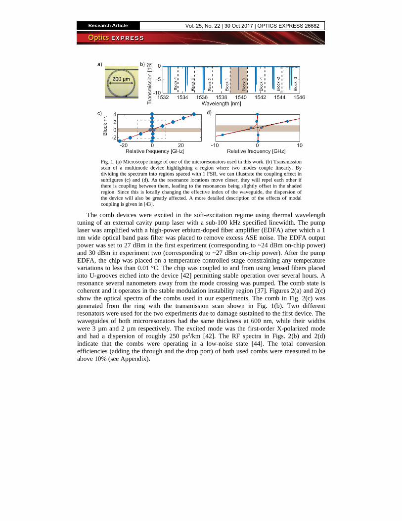
2. Comb generationThe devices consisted of rings with 100 µm radius leading to a comb line spacing of multiples of 230 GHz. SiN microresonator combs with smaller spacings are possible [35,40]. Practical challenges that need to be addressed when going for longer cavity lengths include maintaining low waveguide losses as well as limiting the effects of modal crossings in the ring waveguide. The latter effects could be addressed e.g. by using an arrangement of linearly coupled single-mode cavities [41]. The devices used in this work consisted of a single microring equipped with a drop port as shown in Fig. 1(a). The drop port assisted in filtering out amplified spontaneous emission (ASE) noise that was left around the pump laser while at the same time limiting the amount of pump light that was present at the output port [42]. Contrary to the cavity soliton-based microresonator combs that require anomalous dispersion waveguides, our microresonators were designed to operate in the normal dispersion regime. To initialize the combs from a single continuous wave (CW) laser source using degenerate four-wave mixing, it is however still required to have locally anomalous dispersion. This can be achieved through local perturbations. In our case, the perturbation was caused by coupling between transverse modes [43]. Figures 1(b)-1(d) illustrate the effect of modal coupling where in certain frequency regions the resonance locations, and thus the effective index, are strongly perturbed by the presence of a second (higher order) mode. This leads to anomalous dispersion locally, enabling the degenerate four-wave mixing process [43].
Fig. 1. (a) Microscope image of one of the microresonators used in this work. (b) Transmission scan of a multimode device highlighting a region where two modes couple linearly. By dividing the spectrum into regions spaced with 1 FSR, we can illustrate the coupling effect in subfigures (c) and (d). As the resonance locations move closer, they will repel each other if there is coupling between them, leading to the resonances being slightly offset in the shaded region. Since this is locally changing the effective index of the waveguide, the dispersion of the device will also be greatly affected. A more detailed description of the effects of modal coupling is given in [43].
The comb devices were excited in the soft-excitation regime using thermal wavelength tuning of an external cavity pump laser with a sub-100 kHz specified linewidth. The pump laser was amplified with a high-power erbium-doped fiber amplifier (EDFA) after which a 1 nm wide optical band pass filter was placed to remove excess ASE noise. The EDFA output power was set to 27 dBm in the first experiment (corresponding to ~24 dBm on-chip power) and 30 dBm in experiment two (corresponding to ~27 dBm on-chip power). After the pump EDFA, the chip was placed on a temperature controlled stage constraining any temperature variations to less than 0.01 °C. The chip was coupled to and from using lensed fibers placed into U-grooves etched into the device [42] permitting stable operation over several hours. A resonance several nanometers away from the mode crossing was pumped. The comb state is coherent and it operates in the stable modulation instability region [37]. Figures 2(a) and 2(c) show the optical spectra of the combs used in our experiments. The comb in Fig. 2(c) was generated from the ring with the transmission scan shown in Fig. 1(b). Two different resonators were used for the two experiments due to damage sustained to the first device. The waveguides of both microresonators had the same thickness at 600 nm, while their widths were 3 µm and 2 µm respectively. The excited mode was the first-order X-polarized mode and had a dispersion of roughly 250 ps2/km [42]. The RF spectra in Figs. 2(b) and 2(d) indicate that the combs were operating in a low-noise state [44]. The total conversion efficiencies (adding the through and the drop port) of both used combs were measured to be above 10% (see Appendix).
Fig. 2. (a) and (c) The optical power spectra (taken with 0.1 nm resolution) of the two used combs with 230 GHz and 690 GHz line spacing respectively as seen from their drop ports with the dashed boxes showing the lines used in the communications experiments. The line powers coupled into fiber were between −8.2 dBm and 7.6 dBm for the first ring and between −8.4 dBm and 9.6 dBm for the second ring. (b) and (d) The corresponding RF spectra in red with the noise floor in blue showing that the combs were operating in a low-noise state.
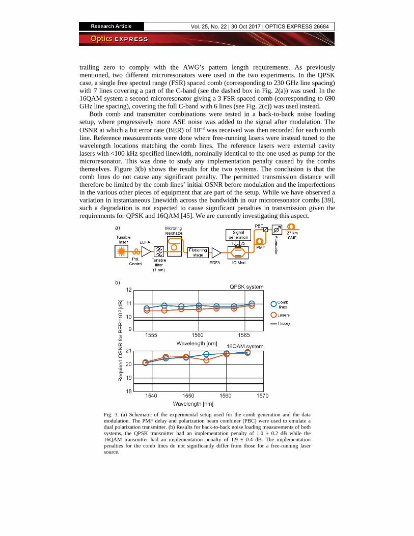
3. Data transmission and resultsBefore modulating data onto the comb lines, we also placed a flattening stage consisting of a programmable pulse shaper and an EDFA ensuring that all lines had equal power. This resulted in a flat spectrum with an optical signal-to-noise ratio (OSNR) of >35 dB per line at 0.1 nm resolution before data modulation. To emulate a WDM system in the laboratory without the large number of components required, all the lines of the frequency comb were instead modulated simultaneously using the same transmitter. See Fig. 3(a) for a description of all the necessary components.
The transmitter
The transmitter consisted of an electro-optic IQ-modulator modulating all the comb lines simultaneously. The modulator was followed by a dual-polarization emulation stage using a polarization maintaining fiber (PMF) corresponding to a delay of more than 20 symbols. The intrinsic dispersion of a 27 km single-mode fiber (SMF) was used to delay and decorrelate the different channels with respect to each other, corresponding to a delay of more than 10 symbols. Since our carriers were spaced several hundred GHz apart, linear crosstalk between the channels is intrinsically not expected to be a problem, thereby we can avoid the widely used even-odd modulation scheme that would require an extra transmitter. Using fiber dispersion as means to decorrelate the channels allows us to emulate a scenario where different data were encoded on each channel to ensure that any correlated nonlinear crosstalk is also avoided. The launch power into this section was only −10 dBm to avoid nonlinearities in this span. Different data sources were connected to the modulator in the two experiments. For the longest reach one, a 12.5 GBd QPSK signal was generated using a pseudorandom binary sequence pattern generator with a pattern length of 215-1 bits (PRBS-15). For the second measurement, the data source was replaced with a newly acquired arbitrary waveform generator (AWG) allowing for the generation of a more spectrally dense QAM signal. The 20GBd 16QAM signal consisted of a triply oversampled PRBS-15 bit pattern with an added
trailing zero to comply with the AWG’s pattern length requirements. As previously mentioned, two different microresonators were used in the two experiments. In the QPSK case, a single free spectral range (FSR) spaced comb (corresponding to 230 GHz line spacing) with 7 lines covering a part of the C-band (see the dashed box in Fig. 2(a)) was used. In the 16QAM system a second microresonator giving a 3 FSR spaced comb (corresponding to 690 GHz line spacing), covering the full C-band with 6 lines (see Fig. 2(c)) was used instead.
Both comb and transmitter combinations were tested in a back-to-back noise loading setup, where progressively more ASE noise was added to the signal after modulation. The OSNR at which a bit error rate (BER) of 10−3 was received was then recorded for each comb line. Reference measurements were done where free-running lasers were instead tuned to the wavelength locations matching the comb lines. The reference lasers were external cavity lasers with <100 kHz specified linewidth, nominally identical to the one used as pump for the microresonator. This was done to study any implementation penalty caused by the combs themselves. Figure 3(b) shows the results for the two systems. The conclusion is that the comb lines do not cause any significant penalty. The permitted transmission distance will therefore be limited by the comb lines’ initial OSNR before modulation and the imperfections in the various other pieces of equipment that are part of the setup. While we have observed a variation in instantaneous linewidth across the bandwidth in our microresonator combs [39], such a degradation is not expected to cause significant penalties in transmission given the requirements for QPSK and 16QAM [45]. We are currently investigating this aspect.
Fig. 3. (a) Schematic of the experimental setup used for the comb generation and the data modulation. The PMF delay and polarization beam combiner (PBC) were used to emulate a dual polarization transmitter. (b) Results for back-to-back noise loading measurements of both systems, the QPSK transmitter had an implementation penalty of 1.0 ± 0.2 dB while the 16QAM transmitter had an implementation penalty of 1.9 ± 0.4 dB. The implementation penalties for the comb lines do not significantly differ from those for a free-running laser source.
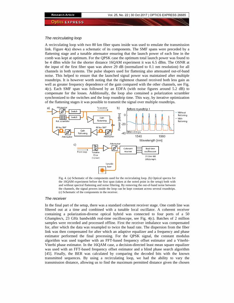
A recirculating loop with two 80 km fiber spans inside was used to emulate the transmission link. Figure 4(a) shows a schematic of its components. The SMF spans were preceded by a flattening stage and a tunable attenuator ensuring that the launch power of each line in the comb was kept at optimum. For the QPSK case the optimum total launch power was found to be 4 dBm while for the shorter distance 16QAM experiment it was 6.5 dBm. The OSNR at the input of the first fiber span was above 29 dB (normalized to 0.1 nm resolution) for all channels in both systems. The pulse shapers used for flattening also attenuated out-of-band noise. This helped to ensure that the launched signal power was maintained after multiple roundtrips. It is however worth noting that the rightmost channel received both less gain as well as greater frequency dependence of the gain compared with the other channels, see Fig. 4(c). Each SMF span was followed by an EDFA (with noise figures around 5.2 dB) to compensate for the losses. Additionally, the loop also contained a polarization scrambler synchronized to the switches and the loop roundtrip time. This way, by iterative optimization of the flattening stages it was possible to transmit the signal over multiple roundtrips.
Fig. 4. (a) Schematic of the components used for the recirculating loop. (b) Optical spectra for the 16QAM experiment before the first span (taken at the noted point in the setup) both with and without spectral flattening and noise filtering. By removing the out-of-band noise between the channels, the signal powers inside the loop can be kept constant across several roundtrips. (c) Schematic of the components in the receiver.
The receiver
In the final part of the setup, there was a standard coherent receiver stage. One comb line was filtered out at a time and combined with a tunable local oscillator. A coherent receiver containing a polarization-diverse optical hybrid was connected to four ports of a 50 GSamples/s, 23 GHz bandwidth real-time oscilloscope, see Fig. 4(c). Batches of 2 million samples were recorded and processed offline. First the receiver imbalance was compensated for, after which the data was resampled to twice the baud rate. The dispersion from the fiber link was then compensated for after which an adaptive equalizer and a frequency and phase estimator performed the final processing. For the QPSK signal, the constant modulus algorithm was used together with an FFT-based frequency offset estimator and a Viterbi-Viterbi phase estimator. In the 16QAM case, a decision-directed least mean square equalizer was used with an FFT-based frequency offset estimator and a blind phase search algorithm [45]. Finally, the BER was calculated by comparing the decoded bits with the known transmitted sequences. By using a recirculating loop, we had the ability to vary the transmission distance, allowing us to find the maximum permitted distance given the chosen
pre-forward error correction (FEC) BER of 10−3 (allowing for FEC overheads below 6.25% [46]).
Results
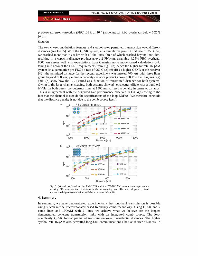
The two chosen modulation formats and symbol rates permitted transmission over different distances (see Fig. 5). With the QPSK system, at a cumulative pre-FEC bit rate of 350 Gb/s, we reached more than 6300 km with all the lines, three of which reached beyond 8000 km, resulting in a capacity-distance product above 2 Pb/s∙km, assuming 6.25% FEC overhead. 8000 km agrees well with expectations from Gaussian noise model-based calculations [47] taking into account the OSNR requirements from Fig. 3(b). Since the higher bit rate 16QAM system (at a cumulative pre-FEC bit rate of 960 Gb/s) requires a higher OSNR at the receiver [48], the permitted distance for the second experiment was instead 700 km, with three lines going beyond 950 km, yielding a capacity-distance product above 630 Tb/s∙km. Figures 5(a) and 5(b) show how the BER varied as a function of transmitted distance for both systems. Owing to the large channel spacing, both systems showed net spectral efficiencies around 0.2 b/s/Hz. In both cases, the outermost line at 1566 nm suffered a penalty in terms of distance. This is in agreement with the degraded gain performance observed in Fig. 4(b) owing to the fact that the channel is outside the specifications of the loop EDFAs. We therefore conclude that the distance penalty is not due to the comb source itself.
Fig. 5. (a) and (b) Result of the PM-QPSK and the PM-16QAM transmission experiments showing BER as a function of distance in the recirculating loop. The insets display received and decoded signal constellations with bit error rates below 10−3.
4. SummaryIn summary, we have demonstrated experimentally that long-haul transmission is possible using silicon nitride microresonator-based frequency comb technology. Using QPSK and 7 comb lines and 16QAM with 6 lines, we achieve what we believe are the longest demonstrated coherent transmission links with an integrated comb source. The low-complexity QPSK format permitted transmission over transatlantic distances. The higher symbol rate 16QAM also permitted long-haul communications albeit at shorter distances. In
the future, more WDM channels will be needed to fill the whole C band with a line spacing compatible with the ITU grid. We envision that the use of mode-locked dark pulses in normal dispersion combs [49], with recently predicted [50] and demonstrated conversion efficiencies >30% [51] will provide a viable solution to achieve a favorable scaling with the number ofchannels and attain high spectral efficiency. The results of this work widen the scope of theusability of silicon photonics-based combs from short-reach high-capacity links to long-haullinks, thus further opening up the path to chip-based transceivers where the coherent nature offrequency combs can be taken advantage of.
Funding The Swedish Research Council (VR); the European Research Council (ERC-2011-AdG-291618 PSOPA); the KA Wallenberg foundation; NSF (ECCS-150957); DARPA (W31P40-13-1-001.8); AFOSR (FA9550-15-1-0211).
Appendix – Comb conversion efficiency The most straight-forward way of defining conversion efficiency is the relation between the optical power in all the newly generated comb lines (excluding the remaining pump line power) compared to the power in the initial pump [51]. Both measurements should be done in the bus waveguide, adjacent to the ring:
comblinescomb
pump
.PP
η = ∑ (1)
Fig. 6. (a) Sketch of a microresonator displaying the measurable power locations (Pin and Pout), the internal locations where the power levels need to be calculated as well as the loss elements. (b) Recorded spectra from the through and the drop ports of the two used microresonators. Thedisplayed conversion efficiencies were calculated by measuring the powers in all the linesexcept for the pump line and comparing it to the throughput power in the off-resonant pumping case. The powers were measured using a grating-based optical spectrum analyzer with 0.1 nmresolution. In both devices, the total conversion efficiency (adding the through and the dropport) exceeded 10%.
Since the optical powers inside the microresonator device cannot be measured directly, we have to extract the relevant information from measurements done at the output ports of our device. Figure 6(a) shows a schematic of the device, the locations where the optical spectrum should be measured and the different loss elements that are not part of the comb generation process itself. Since the device is coupled into using tapered fibers at both ends, we will incur coupling losses at both facets, αc1 and αc2. In addition there will also be some (possibly insignificant) losses due to absorption in the bus waveguide, αwg. In practice, the spectrum can only be measured at the input and the output. The total loss can be measured by pumping the ring resonator off resonance and measuring the output power at the through port:
out,off pump wg c2 in c1 wg c2 .P PP α α α α α= = (2)
After shifting the laser into resonance and initiating the comb, the spectrum can again be measured at the through port giving us the on-resonance output powers:
out,on out,pump out,comblines out ,pump wg c2 comblines ,P P PP P α α= + = +∑ ∑ (3)
where Pout,pump is the power left in the pump line at the output. From Eqs. (1), (2), and (3), we can now extract the conversion efficiency:
out,on out,pump out,on out,pumpcomb
in c1 wg c2 out,off
.P P P P
P Pη
α α α− −
= = (4)
Using Eq. (4) we can thus measure the conversion efficiency of our comb by only looking at the through-port and taking optical spectra in on- and off-resonant pumping situations. A similar calculation can be done for the drop port, assuming the chip-to-fiber coupling losses are identical for the two ports giving effective conversion efficiencies for both output ports.
Figure 6(b) shows the values for the combs that were used in our experiments. The two devices had slightly different gap distances between the ring and the through ports (500 nm vs 300 nm) while having the same 500 nm gap to the drop port leading to the difference in the ratio between the through and drop port conversion efficiencies.