Long Island Liquid Waste Association On-site Septic Contractor Examination Study Guide January 2016 Index: Introduction Page I Code of Ethics - Industry Image Page II Section A - Service Requirement for Certification Page 1 Section B - Safety Equipment, Hygiene and Lifting Techniques Page 1 Section C - Customer Service Procedures Page 2 Section D - Pumping Service Procedures Page 2 Section E - Service Unit Equipment Page 3 Section E - Pumping Equipment Specifications Page 4 Section E - Vehicle Inspection Procedure Page 5 Section F - Line Cleaning Safety Equipment & Procedures Page 8 Section F - Line Cleaning Techniques Page 9 Section G - Additives to Assist Drainage Page 12 Section H- Installation and Repair Page 14 Copyright 2016 Long Island Liquid Waste Association
Transcript
Long Island Liquid Waste Association On-site Septic Contractor Examination Study Guide
January 2016
Index:
Introduction Page I Code of Ethics - Industry Image Page II Section A - Service Requirement for Certification Page 1 Section B - Safety Equipment, Hygiene and Lifting Techniques Page 1 Section C - Customer Service Procedures Page 2 Section D - Pumping Service Procedures Page 2 Section E - Service Unit Equipment Page 3 Section E - Pumping Equipment Specifications Page 4 Section E - Vehicle Inspection Procedure Page 5 Section F - Line Cleaning Safety Equipment & Procedures Page 8 Section F - Line Cleaning Techniques Page 9 Section G - Additives to Assist Drainage Page 12 Section H- Installation and Repair Page 14
Copyright 2016 Long Island Liquid Waste Association
-I-
Introduction
This examination study guide is not intended to replace the need for septic contractors to obtain and learn the Rules and Regulations guiding the servicing and installation of septic systems in Suffolk County. On December 1, 2015 the Suffolk County Legislature adopted a law amending chapter 563 of the Suffolk County Code to modify the laws relating to the Septic Industry Busi-ness Training, which was then signed into law by County Executive Steve Bellone. At this time 11 specialized endorsements were added under the Liquid Waste License. Specialized training is required of any applicant applying for or renewing a Liquid Waste License as of June 2016. The Long Island Liquid Waste Association (LILWA) on-site Septic Contractor Certifi-cation Program has been approved by Suffolk County as a training requirement for en-dorsements A, B, C, D, E, F, G, and I. LILWA Certification Program This program has been developed to improve the standards and image of the Septic In-dustry for the mutual benefit of those serving the industry and those the industry serve. The certification standards program will encourage the industry to improve their perfor-mance and professionalism. How do I Certify LILWA Standards Certification is earned by passing the Long Island Liquid Waste As-sociation on-site Septic Contractor Certification Test of technical skills and industry knowledge. The test is preceded by a review of all materials contained in the test. All questions are either multiple choice or true or false. A test score of 75 or above will be considered passing. LILWA Standards Certification Program should take 2-3 hours
Code of Ethics Companies Utilizing the LILWA Certification Program Shall: 1. Conduct their business in the public interest and adhere to Policies and Procedures relating thereto. 2. Operate constantly in accordance with the best and most fully accepted business practices. 3. Comply with all legally applicable Governmental Regulations. 4. Furnish adequate equipment, supplies and "qualified personnel" to achieve and maintain the highest standards of technical performance. 5. Recognize and respect the rights and privileges of competitors in the true spirit of individual initiative and free competitive enterprise, while offering similar services of constantly increasing quality with a reasonable profit return. 6. Strive for continued improvement of the image and reputation of the industry by practicing good and
enlightened public relations in the community and by keeping the community adequately informed of the function and services of the firm and the industry.
7. Recognize the rights and respect due customers and strive for similar recognition by all employees of his company. 8. Provide safe and sanitary service at fair, equitable and non-discriminatory charges.
Customer Service - Image
Licensed Contractor Shall: 1. Maintain their service equipment in such a manner as to project a clean, efficient image. 2. Maintain a serviceman dress code so that their servicemen project a clean, efficient image. 3. Direct all employees to conduct themselves in a respectful manner in order to improve the image of their company and the industry in general. Licensed Contractor Should: 1. Document Service: A customer service card should be kept on file noting services, locations, etc. This will save the customer money on future services. Familiarity with the customers account and system will improve your company image on the next customer contact for service. 2. Follow up on Service: The customer should be contacted within one week of service. The following questions should be asked. a. Was the service adequately performed? b. Did the serviceman explain how the system functions, why it failed, service options, and provide advice regarding future usage and maintenance? c. Did the serviceman treat the customer and their properties with respect? d. Ask for suggestions and comments. A guarantee should be given when the appropriate service has been performed by the company. Guarantees can be limited to curb customer abuse. They will also help the company by limiting the time a company is obligated to a customer for responsibility for services rendered. A good clear guarantee would benefit both the customer and the service company while improving the company's and industry's image.
-II-
Section A - Standards for Service Qualification 1. A serviceman shall serve as an apprentice, working on the job under the direct supervision of a qualified serviceman for a minimum of 3 months prior to being considered for "Qualification". 2. Additionally, said person will be required to demonstrate his knowledge of: a. Pumping Sanitary Systems b. Line Cleaning c. Application of System Drainage Additives d. System Repairs and Installation e. Safety Procedures. f. Proper operation of all tools, equipment and material he will utilize. g. The ability to diagnose and resolve system failures. 3. No Person shall be dispatched independently for service, represent himself or be represented as a "Qualified Serviceman" until he has met the afore mentioned minimum criterion. 4. Servicemen must be "requalified annually". 5. Drivers of service equipment must complete a Drivers Safety Training Program recognized by Suffolk County Department of Consumer Affairs and maintain a drivers safety training card. Drivers must take a Drivers Safety training course every three years. 6. Servicemen will be subject to RANDOM substance abuse screening .
Section B - Safety Equipment, Hygiene and Lifting Techniques
1. All servicemen must be equipped with suitable uniforms, hand, foot and eye protection during service procedures. Lifting belts should also be considered as a requirement. 2. Servicemen Hygiene: a. Keep cuts and wounds properly medicated and covered while on the job. b. Do not rub eyes, ears or mouth while on the job. c. Treat cuts or abrasions immediately. Cuts should be washed, medicated and covered. d. Wash up after each service call with disinfectant soap. e. Consult a physician regularly and be properly inoculated. 3. Lifting Techniques For Heavy Equipment: a. When lifting, keep your back straight and let your legs do the work. b. Stand close to what you lift with your feet firmly on the ground. c. If you must squat to lift, keep your back straight, knees bent and stomach muscles tight. Lift with your legs. d. When putting the load down, let your legs do most of the work. e. Never trust your body while carrying a heavy load. Turn with your feet, never twist your legs or back. f. Push and do not pull heavy objects. g. Use mechanical help if the load is too heavy. h. Keep your knees bent when working on your back. Get up and stretch frequently. i. Use a ladder instead of jumping from short heights.
Page1
Section C - Customer Service Procedure Questions to be asked of customer on initial contact to prepare serviceman prior to dispatch. 1. Does home have sewer service or on-site sanitary system? 2. Does customer know type of system, location of system, is a plot plan available? 3. Does the customer know what the problem is with the system? 4. Age of home - homes built after 1972 will have a septic tank as primary receiver with leaching pool as overflow - systems prior to 1972 will more than likely consist of two leaching pools. 5. Number of residents utilizing the system? 6. Single or multiple dwelling? 7. Is residence year round or a vacation home? 8. Area of residence? - to determine drainage conditions, water table, etc. 9. Type of water source - well or city? 10. Are there underground utilities on the premises - electric, gas, water, cable, sprinkler system? 11. When was the system last serviced - what service was performed and how frequently? 12. Have drainage additives been applied? If so when, how were they applied and what additive was used? 13. Customer should be made aware of all charges that they may incur. Service options should be discussed to determine desired service and estimated costs. The contractor may elect to discuss costs after system failure diagnosis on sight by his "Certified Serviceman". However, costs and options should be discussed prior to commencing service procedures.
Section D - 1 - Pumping Service Procedure
Servicemen and their assistants must be equipped with suitable uniforms, hand, foot and eye protection dur-ing service procedures. Lifting belts should also be considered as a requirement. Servicemen should look for signs of contamination when servicing any system. 1. On arrival at the service site the serviceman shall introduce himself to the customer, review the specific problem, discuss service options and reach an agreement with the customer as to what service will be performed and the costs of those services. 2. Once the service has been determined the serviceman shall inspect the area for hazards and utilities. The serviceman shall then determine how he will access the service site with his equipment. If a possibility of damage is evident the serviceman shall review the possibilities with the customer for approval. A tarp is recommended to be put on grass and excavated fill to insure neatness to property. 3. The customer should be invited to inspect the sight gauges and volume marking on the service unit prior and after service. 4. The cover of the primary system (septic tank or leaching pool) should be completely exposed and removed to facilitate full access to the system. 5. All solid materials must be removed from both the top and bottom of the system. 6. All internal structure must be inspected by the serviceman, lines, baffles, tee's etc. Should repair be needed, the customer must be advised and repair procedures reviewed. 7. Access covers are to be inspected by the serviceman for defects prior to replacement. Defective covers must be replaced. The cover is to be securely replaced and work site is to be left safe. 8. Should the customer elect to relieve the overflow system the serviceman will follow the same procedures as 4,5,6&7. 9. The serviceman shall make certain that all lines are clear and free flowing.
Page 2
Section D - 1 - Pumping Service Procedures - Continued 10. The serviceman's name and identification shall be legibly and prominently affixed to the customer's invoice. 11. Finalizing service procedure: The serviceman should review the services performed with the customer and make recommendations for future maintenance of the system. The average septic tank should be serviced every 1-2 years to prevent solid waste from entering the leaching area. Commercial grease traps should be fully pumped at least twice a year. 12. Prior to leaving the service site the serviceman shall do a final inspection making certain that the site is left in a clean and safe manner. The serviceman shall also inspect his service unit making sure all tools are in place and secure.
Section D - 2 - Additional Services A. LINE CLEANING: The serviceman shall follow the procedures outlined in the "Line Cleaning Section F" of the LILWA Standards. B. ADDITIVES TO ASSIST DRAINAGE AND WASTE DIGESTION: The serviceman shall follow the procedures outlined in the "Additive Section G" of the LILWA Standards. C. INSTALLATION OF RISERS AND COLLARS: Risers and collars will reduce the cost of future service. They should be recommended to the customer and installed in the following manner: a. Primary system risers/collars must be a minimum of 20" in diameter and no more than 3" below grade. b. Leaching system riser/collars must be a minimum of 6" in diameter and no more than 12" below grade. c. Systems located in traffic areas may be installed at grade level with traffic bearing covers. D. MIXING OF WASTE WITH WATER TO FACILITATE WASTE REMOVAL: 1. Mixing may be performed by, aeration, hydro jetting or manually. When mixing in the primary system, liquid waste must be pumped below the outflow line to prevent solid wastes from entering the leaching area. 2. When utilizing aeration or hydro jetting in a leaching pool the serviceman must not disturb areas 2' from the interior wall of the system. 3. Block systems should not be aerated or hydro-jetted. Customer should be advised of the unsafe nature of block systems and recommend replacement. 4. Serviceman should note his recommendation on customer invoice.
Section E - 1 - Equipment to be carried on Pumping Units/ Service Vans
1. Medical Kit including eye wash and drainage acid neutralizer. 2. Dry Chemical Fire Extinguisher. 3. 5 gallon pail of absorbent - to clean up minor spills. 4. Safety tape and 3 traffic cones to secure work areas in traffic or hazardous areas. 5. Hand tools - long handled shovel, rake, broom, probing bars, lifting hooks, lump hammer, cold chisel, sledgehammer, pipe wrench and several common trap caps. 6. Pumping units should carry sufficient service hose to avoid property damage - minimum of 150' x 3" suction hose is recommended. 7. Equipment for line cleaning. A hand or ribbon snake shall be considered a minimum requirement. 8. All equipment required by D.O.T. - See vehicle inspection Section E-3.
Page 3
Section E -2 - Pumping Equipment Specifications
As of June 23, 2016 dedicated pump trucks are required for the purpose of Cesspool Service, Grease Trap Service, Yellow Grease Service and Portable Restroom Service. Pump trucks must be clearly marked on each side and rear in letters 6" high minimum indicating their specific purpose. A Qualified Serviceman shall utilize and maintain Pumping Equipment meeting the following minimum standards. 1. The truck chassis shall be of the proper Gross Vehicle Weight (GVW) and maintained to transport it's cargo in a safe manner. 2. The tank vessel shall be securely affixed to the chassis frame, within the recommended guide lines of the chassis manufacturer. 3. All valves in direct contact with the liquid waste must be fastened directly to the tank vessel and have and affixed secondary safety cap to prevent accidental spillage. 4. All tank apertures must be provided with a positive closure device to prevent spillage. 5. Discharge valves shall be located at the lower most part of the tank vessel to insure complete discharge. 6. Discharge valves shall have a greater discharge volume than the largest intake valve. 7. Cargo valves must be protected to prevent damage and subsequent spillage. 8. Tank vessels must have surge baffles. The thickness of the baffle(s) must be equal to (minimum) the thickness of the tank shell. The vessel must have one baffle for each 7' of tank shell length. 9. Tank vessels with pressure discharge shall have installed within their pumping system a 10PSI (maximum) pressure relief device. No isolator valve will be allowed between the relief device and the vessel. A non-mechanical system (by-pass) is acceptable providing the maximum working pressure cannot exceed 10 PSI. Vessels with sight eye type indicators shall be restricted to 5 PSI. Operators with sight eye devices should be required to replace them within 6 months of certification as they do not comply with item #4. 10. All tools, hoses and accessories must be enclosed or securely affixed to the service unit to prevent road hazard. 11. All vessels must have sight gauges. Liquid levels are required at the first 1000 gallon level and each 1000 gallon level (minimum) thereafter. Gallonage levels must be permanently marked in 1" lettering with 1/4" brush stroke. 12. Volume identification: All pumping units must be certified as to liquid capacity. Each unit shall carry "In Writing " a capacity certification. The certification shall be provided by an authorized public agency, an independent firm recognized by the vessel manufacturer. The certification shall include the name and address of the certifying agency, name and address of the owner of the equipment, license plate number of the unit and the liquid waste capacity of the unit. The volume of that unit shall be conspicuously and permanently displayed on the drivers side forward most part of the tank vessel in contrasting letters 4" high with a 3/8" brush stroke. 13. The unit and driver of the unit shall be in compliance with all local, state and federal regulations applicable.
Page 4
Section E - 3 - Vehicle Inspection Procedure Recommended Vehicle Inspection Procedure Prior to Dispatch: It shall be the serviceman's responsibility to insure that all service, safety equipment and documents re-quired to perform his duties are safely stored on the service unit. The serviceman shall also inspect his vehicle in accordance with D.O.T. requirements prior to leaving the shop. Walk Around Inspection Procedure: 1. Vehicle preparation: When approaching the vehicle note general condition. If unit is leaning it may indicate a broken spring or flat tire. Look for signs of fuel, oil or water leaks. Review last inspection report. Note any defects re- ported and confirm that necessary repairs were made. Ensure Parking Brake Is Engaged 2. Engine Compartment: Check all hoses for signs of leakage or seeping. Check all wiring for cracked or worn insulation Check all fluid levels - water - oil - etc. 3. Inside Cab: Start engine listen for any unusual sounds Check gauges - oil pressure, ammeter, coolant temperature, warning devices Check condition of controls - Steering play should not exceed - Manual 30/ Power 45 Degrees, Clutch, Accelerator, Foot brake, Parking brake, Transmission, Differential lock, Horn, Wiper/Washer, Headlights, Dimmer Switch, Turn signals, 4 way flasher, Clearance and Marker lights - Check mirror adjustments. Safety Equipment Check: Seat belt, Reflective triangles, Fire Extinguisher - fully charged within arm's reach of driver, Spare flasher/fuses or circuit breakers, Medical Kit, Eye Wash and Drainage Additive Neutralizer. 4. Front of Cab: Steering System: Look for loose, worn, bent, damaged or missing parts. Check: Head Lamps, Turn Signals and Emergency Flasher. Suspension (Both Sides): Check leaf springs for broken or missing parts, leaves out of alignment, or contact with vehicle body. Check u-bolts for loose, cracked or missing parts. Check mounting hardware for cracks, missing bolts or pins. Front Brakes (Both Sides): Assure all components are attached and operational. Check brake lines for leaks or damage and chambers for cracks or insecure mounting. Check brake linings. They should be free of large cracks or missing pieces. No grease or oil should be on the linings or drums. Make certain the pushrod and slack adjuster are mechanically operational. Check for audible air leaks.
Page 5
Section - E - 3 - Walk Around Vehicle Inspection Continued 5. Left (Drivers) Side of Cab: Front Wheel: Check for defective welds, cracks or breaks, especially between hand holes or stud holes - unseated locking rings - broken, missing or loose lugs, studs or clamps, bent or cracked rims. Check for "bleeding" rust stains, defective nuts or elongated stud holes. Spoke wheels should be checked for cracks across spokes. Scuffed or polished areas on either side of the lug indicate a slipped rim. Rims should also be checked for cracks or bends. Valve stem should be straight and equally spaced between wheel spokes. Tire: Check for bulges, leaks, sidewall separation, cuts, exposed fabric, worn spots, proper inflation and contact with any part of the vehicle. Measure tread depth (3/32" Minimum). Frame: Look for cracked, sagging rails, broken or loose bolts and brackets. Mirrors: Check mirrors and frames for damage. 6. Left Side of Service Unit: Fuel Tank: Check for unsecured mounting, leaks or other damage. Check for unsecured cap or loose connections. Pumping System: Check oil levels, inspect drive system looking for leaks, loose bolts, damage to drive line. Inspect pump looking for oil leaks at shaft seals and oil feed lines. Check for cracks, loose bolts and damage to the pump mounting frame. Drain and check muffler separator and secondary overflow check systems for leaks. Body & Frame: Inspect tank tie down system, mounting rails and chassis rails for cracks and loose or worn bolts. Listen for air leaks and bleed air tanks. Check all tools and cabinets making certain all equipment is secure. Check placarding if required. Check marker lights and reflectors. 7. Left Rear Axle (s) Area: Wheels, rim and tires - inspect as in item #5. Examine inside tire, making sure both tires are the same height. Check between tires for debris or contact. Check for flat tires inside and out. Inspect suspension and brakes as described in Item #4. Check flaps and flap frames looking for cracks and loose bolts
Page 6
Section - E - 3 - Walk around Vehicle Inspection Cont. 8. Rear of Service Unit: Check stop, tail, turn signals, emergency flashers, reflectors, clearance marker, backup and license lights. Inspect wiring for cracks and security. Check all valves for leaks and that drip caps are installed with safety chains. Check bumper assembly and rear structure for damage and missing pieces. Check all hoses and tools making certain they are secure. 9. Right Rear Axle (s) Area: Inspect as Item #7 - Left Side 10. Right Side of Service Unit: Inspect as Item #6 - Left Side - Deleting Pump Section Check exhaust system for secure mounting, leaks, exhaust contact to fuel, air or electrical lines. Look for carbon deposits around seams and clamps which indicates exhaust leaks. 11. Right Side of Cab: Inspect as item # 5 - Left side of cab 12. Return to Cab Check: Air Pressure - Pump up air system, check gauge. Check low air pressure warning device by depleting air supply by pumping foot brake. Warning light/buzzer should activate at about 55 PSI or above. Parking Brakes - with seat belt fastened, release brakes. As vehicle begins to move, activate parking brake to check operation. Service Brakes - with seat belt fastened, at about 5 MPH apply brakes. Note any unusual pulling, delay or play in the brake pedal. Pumping System - Engage pump in vacuum position, making sure parking brake is activated, exit cab, inspect drive line, check lubrication system, check vent valve, intake and discharge valves pulling a vacuum through valves to insure proper operation. Disengage pumping system. Paper Work - Sign off on vehicle inspection report, check for inventory sheets, licenses and insurance documents, permits, inspection stickers and medical certificate.
Page 7
Section - F - 1 - Line Cleaning Safety Equipment & Procedures Safety Equipment Required: 1. Full face shield 2. Rubber insert type gloves 3. Rubber boots 4. Protective, water proof clothing 5. Suitable ear protection 6. Lifting belts should also be considered Safety Procedure: Operators must follow OSHA guidelines for confined space entry. Work area must be properly ventilated. A - Electricity and Water - Safety Equipment to be utilized: 1. Safety goggles, rubber insert type gloves and rubber boots. Loose fitting clothing and long hair should be avoided. 2. Ground fault interrupters should be used on all electrical equipment. 3. Three pronged receptacles - properly grounded. 4. Air actuated or sealed electric foot pedal - electric foot pedals are not to be bypassed. 5. When an extension cord is required it shall be waterproof, three pronged and in safe condition. 6. Minimize contact with the sewer cleaning machine and water when working in wet conditions. B - Cable Machines - Safety Procedures: 1. Avoid excessive distance between pipe opening and sewer cleaning machine. The cable is not being controlled when 3' or more of cable is outside of the pipe or machine drum. The cable will be free to loop or create a figure "8" under torque. This condition may subject the operator to injury. Breakage of the cable causing flying debris is also possible. A guide pipe/hose should be utilized if the machine cannot be positioned to maintain the 3' maximum cable exposure. 2. The machine should never be turned on before the blade is placed in the pipe. An exposed rotating blade and cable exposes the operator to injury. 3. Machines operating in "Reverse" position for extended periods of time twist the cable opposite the winding direction allowing the cable to exit the drum. Four feet of cable can exit the drum immediately exposing the operator to injury. 4. Machines should always be positioned as close to the pipe as possible in a stable, dry position. C - Chemical Awareness: 1. Many consumers try to utilize chemicals to clear line stoppages. Many chemicals can cause severe burns, create poisonous gases and destroy line cleaning cable. 2. The customer should be asked if chemicals have been utilized. 3. The serviceman should assume that chemicals are in the system and proceed with caution. 4. If chemicals are detected the serviceman should use extreme caution. The safest accesses for clearing these lines are the main line from the primary receiver or the roof vent. Water jetting is more desirable as the chemical will destroy a cable or ribbon snake.
Page 8
Section - F - 2 - Line Cleaning Techniques A. Basic Techniques for operating Line Cleaning Equipment: 1. Generally, soft obstructions are cleaned best with a high velocity water jet and a cable machine works best with hard obstructions. 2. An arching or torquing cable tells of resistance in the pipe. Work with the cable already in the pipe. Do not continue putting cable into the pipe. 3. Cutting a hole in stoppage with a small tool allows the liquids in the pipe to drain. A second pass with a larger cutting tool is mandatory. 4. When cleaning a sink, always drain the line, then pull the trap before placing the cleaning tool in the pipe. If you must clear thru a trap, use a no tension cable so you can execute the turn without damage to your cable. 5. The best way to execute a "tee" in a line is with the use of a drop head attachment on a cable. 6. Installing a "cleanout" is the best way to clean a pipe when the only access is thru the roof vent. 7. The most effective place to clean a bathtub is thru the overflow. 8. Cleaning roots requires care to avoid getting caught in the pipe and to avoid having to dig up the pipe. 9. If a turn cannot be executed with the machine in "forward" try a 3-5 second operation of the machine in "reverse". B. Proper Techniques For Clearing Sewer and Drain Stoppages: 1. Main Sewer or Cesspool Lines: a. Determine the lowest point where sewage is backing up. b. Locate house trap. c. If main line is suspended, the serviceman must find a receptacle to catch spillage to prevent damage to floors, carpeting, etc. d. Proceed to open outflow side of house trap first. Care should be taken as the line might be under pressure. Open cap slowly to relieve pressure and water. e. If no pressure was experienced flush the line with water from the toilet bowl and check trap to see if there is any flow of water. f. After stoppage location has been determined, securely set line cleaning machine in the working area. g. Clean line using a small cutting tool to clear stoppage. h. Flush line with heavy amounts of water. i. Use large cutting head to clear line to full diameter. j. Secure all trap caps and clean area of any debris or water, leaving the area in a safe, clean condition. 2. Kitchen Sink and Basin Lines: a. Check to see if water is backing up only in the kitchen sink. Make sure water is not backing up from the main waste line into the kitchen sink. b. Once it has been determined that the sink line is blocked: 1. Look for a cleanout in line if pipe is exposed. 2. If a cleanout is not accessible - drain the sink and remove trap from under the sink. 3. Set machine up near cleanout or the pipe where the trap was removed. 4. Clean line with a small cutter first, working up to the same size as pipe diameter. 5. Install trap or clean out plug and flush line with hot water to clear debris. 6. If no cleanouts are available and chemicals are in the line, the safest place to clean line would be the roof vent.
Page 9
Section - F - 2 - Line Cleaning Techniques Continued 3. Bathtub Stoppages: a. Flush toilet bowl and check for a reaction in the tub. b. Fill up basin and let water out, again checking for a reaction in the tub. c. Once it is determined that the tub is clogged: 1. Inspect line below for any defects such as, leaks, rot and distance from tub to waste stack. 2. Remove trip lever located under water controls. 3. Clean line through overflow going around trap and into waste line. 4. Flush line with heavy amounts of water to remove debris from line. 5. Reset trap lever securely and check for leaks. 6. Stand pipe or barrel wastes are other types of mechanisms on bathtubs. Loosen and remove top and remove the stopper. Then use procedure as above to clean line. 4. Shower Drain Line Stoppages: a. Check drain pipe to determine materials, cast iron, pvc, copper, lead, etc. b. Look for a cleanout. If no cleanout is available - line must be cleared through the shower stall drain. c. If the line is lead be very careful cleaning line. Use a very fine cable with a coiled tip and no blade - hand feed through the trap d. Cutting blades are to be used on lines other than lead. e. Flush line with heavy amounts of water to remove debris. 5. Washing Machine Drain Lines: a. Check to make sure the washer line is blocked and not the main or a branch line seeking the lowest level in the washing machine line. b. Check for a cleanout - if no cleanout is available; 1. Push cable with a small blade to the bottom of the trap. 2. Turn on the machine and jump the trap and clean line to the end. 3. Flush line with water to clear debris. 6. Urinal Stoppages: a. Urinals with external traps: 1. Remove cleanout plug 2. Clear line using standard line cleaning procedures. 3. Replace cleanout plug and flush water through the urinal to clear debris. b. Urinals with internal traps: 1. Turn off water to urinal, disconnect piping and remove unit from wall. . 2. Clear line through wall using standard line cleaning procedures. 3. Run water through line to wash out debris. 4. Check urinal for foreign matter at opening on back of unit. 5. Re-install urinal on wall using a new neoprene gasket, tighten bolts evenly to prevent cracking. c. Floor mounted Urinals: 1. Run thin cable through trap by hand. 2. Run machine to clear line. 3. Pull cable back by hand. 4. Flush with water to clear debris
Page 10
Section - F - 2 - Line Cleaning Continued 7. Toilet Bowl Stoppages: a. Determine if toilet bowl is clogged. Make sure water is not backing up due to main or branch line stoppage. 1. Run water in another fixture to see if water rises, if not, the stoppage is in the toilet bowl. 2. Use toilet auger and run through toilet bowl turning the handle as you push down through the trap. Pull auger back looking for foreign material. 3. Run water through the bowl slowly, regulating it by valve on the flushometer or by the tank ball in the toilet tank. 4. If water runs through, flush three times with toilet paper to check for proper operation and clear debris from the bowl and line. b. If stoppage cannot be cleared from top side of the bowl: 1. Turn off water and remove tank and bowl from the floor. 2. Turn bowl over and check to see if bowl has stoppage at bottom opening. If so remove the stoppage. 3. If stoppage is not located at the bottom opening, run auger up from bottom of bowl to push stoppage back into the toilet. 4. Check lead bend or waste pipe at floor making sure it is clear of debris. 5. Reset toilet using new flange bolts and wax seal. If floor is uneven, set the toilet in plaster bed. 8. Clearing Exterior Main and Overflow Lines: a. Main line - Locate exposed fresh air vent, dig up house trap exposing incoming and outflow sides of trap and follow Procedures in B- 1 PG 9 "Main sewer & Cesspool Lines" b. Overflow Lines - Determine that stoppage is between systems by inspecting each end of line for obstructions and water levels. Follow procedures as in B1 F-J, PG 9" Main Sewer & Cesspool Lines". 1. In the event of a deep line a guide pipe must be utilized. 2. Should a 90 Degree Elbow be located on the outflow line of the primary system, the line should be cleaned from the overflow system back to the primary system.
Section - F - 3 - Line Cleaning - Water Jetting Procedures - Pressures over 1000 PSI
a. Safety Equipment & Procedures: Refer to equipment required in Section - F - 1, Page 8 b. Safety Procedures: 1. The line cleaning hose must have a "Dis-Similar Color" leader hose of at least 10' in length to warn operator of nozzle location. 2. The pressure system must not be engaged until the leader hose is fully extended into the sanitary line. 3. Systems in excess of 2000PSI must be operated by two persons. 4. A foot valve or dump valve must be immediately accessible to the operator. 5. A leader pipe should be utilized to prevent the nozzle reversing in the line. c. Proper techniques clearing sewer and drain stoppages refer to Section - F -2. d. Care should be taken to prevent water damage when clearing lines from inside traps. When possible lines should be cleared from their lowest end outside the building
Page 11
Section - G - Additives to Assist Drainage Additives utilized to improve drainage must be applied in accordance with the manufacturers recom-mendation and be documented by the manufacturer to be harmless to the environment. 1. Training: a. Servicemen are to have a training period of 3 months prior to being considered as "Qualified to Handle System Additives". Additionally, said person demonstrate his ability and knowledge of: 1. Handling of drainage acids and bacteria products. 2. Proper usage of each material. 3. Use of safety equipment and safety procedures. Servicemen safety procedures should be reviewed every 6 months. 2. Safety Equipment Required: a. Face Shield - goggles would be acceptable without side vents. b. Drainage Acid Neutralizer - baking soda, lime or soda ash are suitable neutralizers. c. Rubber or vinyl gloves must be used in handling drainage acid. d. Acid resistant uniforms must be worn. e. Rubber or vinyl suits must be worn over uniforms. f. Rubbers to fit over shoes are suggested. 3. Handling Procedures: Drainage acid is a corrosive liquid having a low PH. Extreme caution is required while handling and transporting this material. In the event of contact with the skin the area should be flushed with water for a minimum of 20 minutes, neutralizer applied and a physician should be consulted. a. Drainage acid container must meet Department of Transportation (D.O.T.) requirements and shall be of a Hazardous Substance (U.N.) standard. b. Containers must be inspected by serviceman before and after each use for damage. c. Personnel safety equipment must be worn at all times while handling drainage acid. d. The serviceman must locate a working water supply at the job site prior to applying additives. e. Caps and vents must be removed and checked for damage and replaced securely prior to lifting containers. f. Drainage acid containers must never be lifted above the waist. g. Containers should be carried in such a manner as to have the thumb placed over the vent cap. h. Containers are to be handled gently and never dropped or thrown. i. The serviceman is responsible for securing containers on his service unit, maintaining proper labeling and shipping papers. j. Driver is required to posses a current medical card. (A medical card is valid for 2 YEARS from issuance, however, if you change jobs, it is not transferable and a new card must be obtained listing new employer.) 4. Application Procedures: a. Drainage Acid: Is to be added to promote drainage in direct contact section of the disposal system. 1. Drainage acid is to be added directly to the leaching system only. 2. Drainage acid ratios should not exceed 1% of the systems total volume - 10 Gallons to each 1000 Gallons of Leaching Systems Volume. The PH of a sanitary system must never be below 3.
Page 12
Section - G - Drainage Additive Application Continued b. Bacteria/Enzymes are to be added to sanitary systems for maintenance purposes - to keep the system flowing: 1. Bacteria/Enzymes may be applied to the primary waste receiver immediately after pumping service. They may also be applied to the leaching system immediately after service or 4 weeks after service if drainage acid has been utilized. 2. Bacteria/Enzymes may be utilized for monthly maintenance applied in accordance with the manufacturers recommendations.
5. Storage and Transportation - Drainage Acid: a. Storage: 1. A bulk storage tank must have a containment of 110% of tank volume. A bulk storage tank also requires Health Department approval and permits, State registration and local town permits. 2. Containers must be contained in a locking closure. Container storage exceeding 275 gallons requires a permit from the health department. This calculation is based on total amount of ALL hazardous material stored on site including: diesel fuel, solvents, etc. 3. Emergency shower and eye wash must be located within 50' of the storage area. 4. Product identification, safety rules and material safety data sheets must be posted. 5. Many towns now require an emergency response plan along with the proper permits in the event of a spill. b. Transportation: 1. Containers must be UN/ DOT APPROVED. 2. Containers must be transported in a closed, locked cabinet or compartment. 3. Product identification, material safety data sheets and inventory sheets/ shipping papers must accompany materials in transport. 4. Containers must be labeled at all times. Service units carrying more than 12- 5 gallon containers or more than 1000LBS. must be permanently placarded and the driver must have a CDL HAZMAT endorsement.
Page 13
Section - H - Installation and Repair No company shall install or repair sanitary systems without meeting the following criteria: a. The company shall assure proper operation of ALL equipment. Safety procedures, and installation and repair procedures. b. The company must maintain no less than $1,000,000 of liability Insurance Surety bond . c. The company must carry all local and state licenses pertaining to system installation. d. The company must obtain a utility mark-out from a mark- out service. 1. Training as per Sections A & B - Additionally: a. Machine Operators 1. All heavy machine operators must be properly trained for each piece of equipment he will operate. 2. Operator must pass a practical as well as written test on each piece of equipment he will operate before qualifying to operate that equipment without a certified operator present. b. Ground Crew 1. There shall be no less than one qualified person on the ground crew at all times. 2. Qualified knowledge shall include: a. Knowledge of proper safety and installation procedures in accordance with all local and county Board of Health Standards. b. Knowledge of Department of Transportation laws regarding transporting heavy equipment, tying down and covering laws, as well as weight restricted road in the area in which they are working. c. Knowledge of environmental laws as to the proper disposal of debris and dirt. c. Drivers 1. All drivers must have obtained the proper commercial driver license with the correct endorsements for any vehicle he may drive as well as a valid medical card. 2. Loads must be covered and strapped down properly. 3. All drivers are responsible for safety inspections of their vehicles and documentation. 2. Safety Equipment / Procedures: As Section B - Additionally: 1. It is recommended that one person per crew should have knowledge of C.P.R. and Basic First Aid. 2. A basic first aid kit must accompany every crew. 3. Flags, cones or lights must be carried by each crew to properly distinguish construction sites and hazards. 4. When exiting a job site a traffic control person must be utilized. 5. Emergency telephone numbers shall be posted in the cab of each vehicle - Lighting, water, telephone and cable. 6. All lifting chains, lifters and straps shall not exceed manufacturers recommendations. 7. Manufacturers instructions as to proper lifting procedures must be followed. 8. Gloves, safety boots, hard hats and protective eye wear shall be worn by all members of the crew and all personnel on the job site. 9. Ladders shall be provided to prevent jumping in and out of trenches and excavated areas. 10. All Applicable Occupational Safety and Health Administration (OSHA) Procedures shall be followed. 3. Pre - Installation Procedures: a. All utility companies must be called and asked to mark out their appropriated lines. (Case numbers required)
Page 14
Section - H - Installation and Repair Continued b. All consumer owned utilities must be located including - electric, water, gas, cable, sprinklers, swimming pool lines, etc. c. Under ground storage tanks must be located. d. A clear access path shall be determined and the customer notified of such access and possible damages that might be experienced, if any. e. The existing system must be located. f. A suitable, legal and authorized disposal site for excess soil and debris must be located and utilized. g All required permits shall be obtained prior to installation. h. A written proposal as to what is being installed shall be given to the customer prior to any work being done. The proposal shall: 1. Include the size, water volume and location where the new structure will be installed. 2. Clearly state what guarantees are applicable, if any, by the installer and/or the manufacturer. 3. Type, size and diameter of pipe to be used. 4. A schematic diagram showing the system layout in relation to the existing buildings. 5. A maintenance schedule and recommended usage of the new system - proper materials to enter system/ pumping every 2-3 years etc. 4. Materials and Installation:
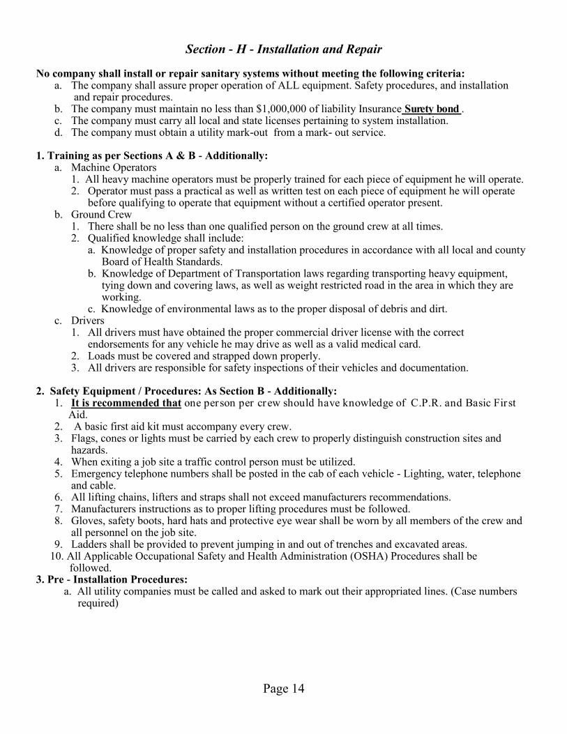
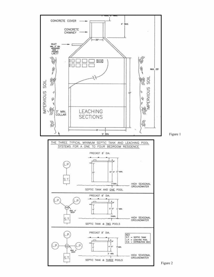
a. Block structures should not be installed. b. All materials installed should carry manufacturers warranty and be approved by all local agencies. c. All new materials - tanks, drainage rings and domes shall be permanently and clearly marked by the manufacturer. The markings should be in 6" x ½" letters stating the dimensions and water volume of each section. d. Existing system: Upon installation of a new overflow, the entire system should be inspected. System should be inspected for: 1. Structural integrity. 2. The main pool should be checked to determine whether solids are being contained or getting into leaching area is missing. 3. Existing outflow line levels should be checked to assure proper drainage to leaching areas. e. New overflows and replacement systems must meet existing Board of Health requirements. f. Main cesspools are to be brought to grade and overflows brought to a minimum of 12" below grade. g. All access covers shall be a minimum of 20" diameter. h. Cover on main pool or septic tank must be insect-proof and easy to handle for homeowners access for checking the system. Locking type should be recommended. 5. Suffolk County Leaching Pool Requirements: a. Typical Leaching Pool Layout: A typical leaching pool is shown in Figure 1. Typical leaching pool
layouts are shown in Figure 2. b. Distance to ground water: The bottom of any leaching pool shall be at least three feet above the
highest recorded ground water level at the proposed system’s location and at least two feet for shallow alternative systems approved by Suffolk County Department of Health Services.
c. Pipe Directly: The leaching pools shall be piped directly from the septic tank or a distribution box (see Figure 2).
d. Precast Reinforced Concrete: Leaching pools are to be constructed of precast reinforced concrete (or equal) leaching structure, solid dome and/or slabs
Page 15
Section - H - Installation and Repair Continued e. Diameter: Leaching pools shall be a minimum of eight feet in outside diameter. f. Multiple Pools Of Uniform Size: When more than one leaching pool is used, all pools shall be of
nominally equal size. g. Maximum depth of Leaching pool: The maximum permissible depth of a precast concrete leaching
pool is twenty-five (25) feet below grade. h. Sand and Gravel Required: The effective leaching area of a leaching pool (below the inlet pipe)
shall be installed entirely in sand and gravel, acceptable to the Department. 6. Cover Requirements: a. Precast Reinforced Concrete: All covers, when not required to be brought to grade, shall be of pre
cast reinforced concrete (or equal). b. Diameter: Covers over three feet in diameter are not permitted. c. Cast-iron Covers: All cast-iron covers shall be set at finished grade, be locking, watertight, insect-
proof, and be approved for sewerage use. 7. Sewer Line Requirements The following criteria apply to the design and construction of sewer lines for subsurface sewerage disposal systems: a. All sewer lines shall be a minimum of four inches in diameter. b. There shall be a length of cast-iron sewer line extending through the foundation to a point a
minimum of two feet beyond the foundation wall. c. The sewer line from the building to the septic tank shall have a minimum pitch of one-quarter inch
per foot and a clean-out or manhole every fifty (50) feet. d. The sewer lines from the septic tank to the leaching pool(s) shall have a minimum pitch of one-
eighth inch per foot. e. When using more than one typical leaching pool, all sewer lines from the distribution box to the pools shall be set in the distribution box at the same elevation.