Long Microwave-Photonic Variable Delay ofLinear Frequency Modulated Waveforms
Ofir Klinger, Yonatan Stern, Thomas Schneider, Kambiz Jamshidi, and Avi Zadok
Abstract— The long, microwave-photonic variable delay of theimpulse response of linear frequency-modulated (LFM) wave-forms is proposed and demonstrated experimentally. The delaymethod is based on the application of a variable frequency offsetto one side-band of an LFM-modulated optical carrier. Due tothe time-frequency ambiguity properties of the LFM signal, theeffect of the frequency offset on the impulse response is nearlyequivalent to that of a group delay. Numerical simulations suggestnegligible degradations in the resolution, peak-to-side-lobe ratioand integrated side-lobe ratio of the processed LFM waveform.Experiments demonstrate the delay of a 500-MHz-wide LFMsignal by up to 250 ns. The method is applicable to LFMwaveforms of arbitrary bandwidth and central radio-frequency.The long delays make the method attractive for optical beam-steering in large phased-array radars.
Index Terms— Linear frequency modulated (LFM) waveforms,microwave-photonics, optical beam forming, variable opticaldelay.
I. INTRODUCTION
M ICROWAVE photonics (MWP) has been a prolific areaof research for over thirty years. MWP processing
provides several potential advantages [1]: low propagation lossin optical fibers; ultra-broad transmission bandwidth; immu-nity to electro-magnetic interference; availability of high-bandwidth electro-optic modulators and detectors; potential forlight-weight, small-footprint modules etc.
One promising potential application of MWP, which isbeing investigated for over twenty years [2], is the opticalimplementation of radio-frequency (RF) delay lines. Suchdelay lines are critical components in beam steering withinphased-array radar systems [3]. When broadband radar signalsare used, variable group delay elements, rather then phasedelays, are necessary to avoid angular dispersion of the beam[4]. Such true time delay (TTD) elements must accommodatebroadband RF waveforms and comply with stringent distortionrequirements [5]. Large antenna arrays require delay variationsof tens of ns or longer. The variable TTD of high-frequency
Manuscript received October 5, 2011; revised October 21, 2011; acceptedNovember 9, 2011. Date of publication November 18, 2011; date of currentversion January 18, 2012. This work was supported in part by the German-Israeli Foundation under Grant I-2219-1978.10/2009.
T. Schneider and K. Jamshidi are with Institut für Hochfrequenztechnik,Hochschule für Telekommunikation, Leipzig D-04277, Germany (e-mail:[email protected]; [email protected]).
Color versions of one or more of the figures in this letter are availableonline at http://ieeexplore.ieee.org.
Digital Object Identifier 10.1109/LPT.2011.2176483
waveforms using RF cables tends to be lossy and bulky,rendering potential MWP alternatives appealing.
Numerous methods for the realization of MWP TTDelements have been proposed and demonstrated. Examplesinclude switching among fiber paths of different lengths[5], [6], dispersive elements in conjunction with variable-wavelength sources [7], [8], and combinations of the abovemethods [9]. Other techniques employ reconfigurable inte-grated devices [10-12], and group velocity modifications(’slow light’ [4]) in fibers [13-15], and semiconductor opti-cal amplifiers [16]. Despite considerable progress, the real-ization of MWP TTDs that are continuously variable overtens of ns and accommodate broadband waveforms remainschallenging.
In this letter, we explore the potential benefits of a sig-nificant relaxation in the objective of MWP delay elements.Rather then target the universal TTD of any waveform, wefocus on the processing of a particular group of signals that isprevalent in many radar systems: the linear frequency modu-lated (LFM) waveforms. The instantaneous frequency of thesesignals varies linearly with time, spanning a broad bandwidthover long durations. LFM signals are simple to generateand process. With proper post-detection processing, they arecompressed into an impulse response which is characterized bya high spatial resolution and low side-lobes. LFM signals areof constant magnitude, and they circumvent the transmissionof short, high-peak power pulses [17].
Our proposed method of MWP TTD takes advantage of theinherent ambiguity between temporal delays and frequencyoffsets in LFM signals. The LFM waveform modulates anoptical carrier, and one of the side-bands is filtered out.(Note that universal MWP-TTD elements based on a singleoptical side-band were previously proposed and demonstrated[4], [13-15].) A frequency offset is applied to the remainingside-band, using an electro-optic phase modulator. Followingdetection, the recovered RF signal is indistinguishable froma delayed replica of the original LFM shape (except forshort segments near its temporal edges). Simulations showthat the impulse responses of manipulated waveforms areeffectively delayed, with only marginal degradations in theirfigures of merit. The impulse response of 500 MHz-wideLFM signals is experimentally delayed by up to 250 ns. Incompromising the universality of the TTD element, we areable to scale the effective delay of LFM waveforms towardsthe requirements of large phased array antennas. Furthermore,the proposed method is very simple and requires only a fewelements.
KLINGER et al.: LONG MWP VARIABLE DELAY OF LFM WAVEFORMS 201
f(t)
t
τOriginal
�f
Fig. 1. Instantaneous frequencies of LFM waveforms, illustrating theambiguity between a frequency offset and a temporal delay. Black solid:original LFM (1). Red solid: delayed LFM (1). Black dashed: frequency-offset LFM (2).
II. PRINCIPLE OF OPERATION
An LFM waveform of duration T , bandwidth B and centralradio frequency f0 can be expressed as:
ALFM (t) = A0 cos(
2π f0t + π B/T t2
)rect
(t/T
), (1)
where A0 is a constant magnitude, t denotes time andrect (ξ) = 1 for |ξ | ≤ 0.5 and equals zero elsewhere. Theinstantaneous frequency f (t) of the waveform is linearlysweeping between f0 ± 1
2 B along the waveform duration.Suppose next that a phase offset �φ and a frequency offset
� f are introduced to the LFM waveform of (1), so that:
AoffsetLFM (t) = A0 cos
[�φ + 2π ( f0 + � f ) t + π
B
Tt2
]
× rect
(t
T
). (2)
The frequency-offset waveform closely resembled a replica of(1) that is temporally delayed by τ , provided that:
� f = Bτ/
T, (3)
�φ = 2π f0τ + π Bτ 2/
T . (4)
When (3) and (4) are met, differences between (2) and adelayed replica of (1) are confined to the edges of the rec-tangular temporal window, which is not delayed (see Fig. 1).As long as τ << T (� f << B), the differences betweenthe impulse responses of the offset waveform and the ’trulydelayed’ one are expected to be negligible. Since T is typicallymany μs long, substantial delays to the impulse responseshould be possible, with tolerable performance degradation.The adjustment of �φ according to (4) is necessary to avoidspatial distortion of the broadband transmitted beam [4].
Figure 2 shows the simulated impulse responses of theLFM waveforms of (1)-(2), with T = 5μs, B = 500 MHz,f0 = 7.5 GHz and τ = 100 ns. The impulse response ofthe frequency offset waveform is effectively delayed by τ .The ratio between the peak of the main lobe and that of thehighest side-lobe (PSL ratio) of the offset and ideal waveformsare 37.8 dB and 39.5 dB, respectively. The ratio of the energywithin the main lobe to the energy outside it, known as theintegrated side-lobe ratio (ISLR) [3], is 27.6 dB for bothwaveforms. The full width at half maximum (FWHM) of theimpulse response main lobe, signifying resolution, is 2.5 nsfor both waveforms. Both the PSL ratio and the ISLR remainabove 20 dB for delays up to τ = 0.2T = 1μs.
−100 0 100 200 300−80
−70
−60
−50
−40
−30
−20
−10
0
Time [ns]
Impu
lse
resp
. mag
. [dB
]
Ideal LFMDelayed ideal LFMProcessed LFM
Fig. 2. Simulated impulse responses of LFM waveforms (T = 5 μs, B =500 MHz, f0 = 7.5 GHz). Blue solid: original waveform (1). Green dashed:delayed waveform, τ = 100 ns (1). Red solid: frequency-offset waveform,� f = 10 MHz (2).
Arbitrarywaveformgenerator
Reference LFM
LFMRF mixer
RF localoscillator
Samplingoscilloscope
Offset LFM
RF mixer
PCPC
CWlaser
Up-converted LFM
31
2
FBG
PC
Rampwaveform
Photodetector
Coupler50:50
Phasemodulator
Amplitudemodulator
EDFA
DSP
Coupler50:50
Fig. 3. Experimental setup for the variable delay of the impulse responseof LFM waveforms. PC: polarization controller. EDFA: erbium-doped fiberamplifier.
III. EXPERIMENTAL RESULTS
Fig. 3 shows the experimental setup for the variable delayof the impulse response of LFM waveforms. The output of acontinuous wave (CW) laser diode is split in two paths. Lightin the upper path is modulated by an electro-optic amplitudemodulator, driven by an LFM waveform (T = 5μs, B =500 MHz) from the output of an arbitrary waveform generator(AWG). The central radio frequency of the LFM signal is up-converted to f0 = 7.5 GHz using an RF mixer. A narrowbandfiber Bragg grating (FBG) retains one of the modulationside-bands and rejects the optical carrier and the other side-band. The remaining side-band undergoes a frequency offset,introduced by an electro-optic phase modulator that is drivenby a ramp waveform of magnitude V and period 1/� f :
φ (t) = (πV
/Vπ
) ∞∑n=−∞
(t · � f − n) · rect (t · � f − n) . (5)
When the ramp waveform magnitude is adjusted toV = 2Vπ , the phase modulation discontinuities are removed,providing an effective frequency offset of � f . The processedside-band is mixed with the original optical carrier, whichis retained in the lower path (Fig. 3). A modified electricalLFM waveform is reconstructed through the beating of thecarrier and side-band on a broadband detector. The detectedwaveform is down-converted to an intermediate central
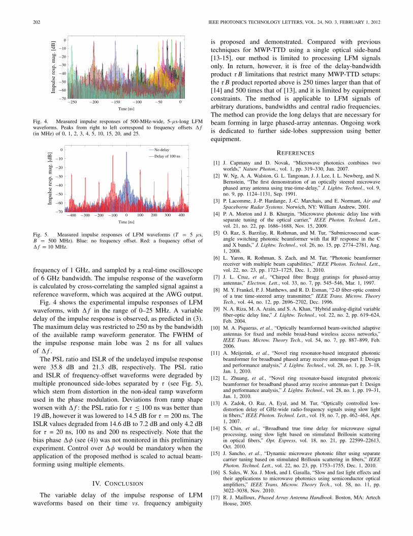
Fig. 4. Measured impulse responses of 500-MHz-wide, 5-μs-long LFMwaveforms. Peaks from right to left correspond to frequency offsets � f(in MHz) of 0, 1, 2, 3, 4, 5, 10, 15, 20, and 25.
−400 −300 −200 −100 0 100 200 300 400−70
−60
−50
−40
−30
−20
−10
0
Time [ns]
Impu
lse
resp
. mag
. [dB
]
No delay
Delay of 100 ns
Fig. 5. Measured impulse responses of LFM waveforms (T = 5 μs,B = 500 MHz). Blue: no frequency offset. Red: a frequency offset of� f = 10 MHz.
frequency of 1 GHz, and sampled by a real-time oscilloscopeof 6 GHz bandwidth. The impulse response of the waveformis calculated by cross-correlating the sampled signal against areference waveform, which was acquired at the AWG output.
Fig. 4 shows the experimental impulse responses of LFMwaveforms, with � f in the range of 0–25 MHz. A variabledelay of the impulse response is observed, as predicted in (3).The maximum delay was restricted to 250 ns by the bandwidthof the available ramp waveform generator. The FWHM ofthe impulse response main lobe was 2 ns for all valuesof � f .
The PSL ratio and ISLR of the undelayed impulse responsewere 35.8 dB and 21.3 dB, respectively. The PSL ratioand ISLR of frequency-offset waveforms were degraded bymultiple pronounced side-lobes separated by τ (see Fig. 5),which stem from distortion in the non-ideal ramp waveformused in the phase modulation. Deviations from ramp shapeworsen with � f : the PSL ratio for τ ≤ 100 ns was better than19 dB, however it was lowered to 14.5 dB for τ = 200 ns. TheISLR values degraded from 14.6 dB to 7.2 dB and only 4.2 dBfor τ = 20 ns, 100 ns and 200 ns respectively. Note that thebias phase �φ (see (4)) was not monitored in this preliminaryexperiment. Control over �φ would be mandatory when theapplication of the proposed method is scaled to actual beam-forming using multiple elements.
IV. CONCLUSION
The variable delay of the impulse response of LFMwaveforms based on their time vs. frequency ambiguity
is proposed and demonstrated. Compared with previoustechniques for MWP-TTD using a single optical side-band[13-15], our method is limited to processing LFM signalsonly. In return, however, it is free of the delay-bandwidthproduct τ B limitations that restrict many MWP-TTD setups:the τ B product reported above is 250 times larger than that of[14] and 500 times that of [13], and it is limited by equipmentconstraints. The method is applicable to LFM signals ofarbitrary durations, bandwidths and central radio frequencies.The method can provide the long delays that are necessary forbeam forming in large phased-array antennas. Ongoing workis dedicated to further side-lobes suppression using betterequipment.
REFERENCES
[1] J. Capmany and D. Novak, “Microwave photonics combines twoworlds,” Nature Photon., vol. 1, pp. 319–330, Jun. 2007.
[2] W. Ng, A. A. Walston, G. L. Tangonan, J. J. Lee, I. L. Newberg, and N.Bernstein, “The first demonstration of an optically steered microwavephased array antenna using true-time-delay,” J. Lightw. Technol., vol. 9,no. 9, pp. 1124–1131, Sep. 1991.
[3] P. Lacomme, J.-P. Hardange, J.-C. Marchais, and E. Normant, Air andSpaceborne Radar Systems. Norwich, NY: William Andrew, 2001.
[4] P. A. Morton and J. B. Khurgin, “Microwave photonic delay line withseparate tuning of the optical carrier,” IEEE Photon. Technol. Lett.,vol. 21, no. 22, pp. 1686–1688, Nov. 15, 2009.
[5] O. Raz, S. Barzilay, R. Rothman, and M. Tur, “Submicrosecond scan-angle switching photonic beamformer with flat RF response in the Cand X bands,” J. Lightw. Technol., vol. 26, no. 15, pp. 2774–2781, Aug.1, 2008.
[6] L. Yaron, R. Rothman, S. Zach, and M. Tur, “Photonic beamformerreceiver with multiple beam capabilities,” IEEE Photon. Technol. Lett.,vol. 22, no. 23, pp. 1723–1725, Dec. 1, 2010.
[7] J. L. Cruz, et al., “Chirped fibre Bragg gratings for phased-arrayantennas,” Electron. Lett., vol. 33, no. 7, pp. 545–546, Mar. 1, 1997.
[8] M. Y. Frankel, P. J. Matthews, and R. D. Esman, “2-D fiber-optic controlof a true time-steered array transmitter,” IEEE Trans. Microw. TheoryTech., vol. 44, no. 12, pp. 2696–2702, Dec. 1996.
[9] N. A. Riza, M. A. Arain, and S. A. Khan, “Hybrid analog-digital variablefiber-optic delay line,” J. Lightw. Technol., vol. 22, no. 2, pp. 619–624,Feb. 2004.
[10] M. A. Piqueras, et al., “Optically beamformed beam-switched adaptiveantennas for fixed and mobile broad-band wireless access networks,”IEEE Trans. Microw. Theory Tech., vol. 54, no. 7, pp. 887–899, Feb.2006.
[11] A. Meijerink, et al., “Novel ring resonator-based integrated photonicbeamformer for broadband phased array receive antennas-part I: Designand performance analysis,” J. Lightw. Technol., vol. 28, no. 1, pp. 3–18,Jan. 1, 2010.
[12] L. Zhuang, et al., “Novel ring resonator-based integrated photonicbeamformer for broadband phased array receive antennas-part I: Designand performance analysis,” J. Lightw. Technol., vol. 28, no. 1, pp. 19–31,Jan. 1, 2010.
[13] A. Zadok, O. Raz, A. Eyal, and M. Tur, “Optically controlled low-distortion delay of GHz-wide radio-frequency signals using slow lightin fibers,” IEEE Photon. Technol. Lett., vol. 19, no. 7, pp. 462–464, Apr.1, 2007.
[14] S. Chin, et al., “Broadband true time delay for microwave signalprocessing, using slow light based on stimulated Brillouin scatteringin optical fibers,” Opt. Express, vol. 18, no. 21, pp. 22599–22613,Oct. 2010.
[15] J. Sancho, et al., “Dynamic microwave photonic filter using separatecarrier tuning based on stimulated Brillouin scattering in fibers,” IEEEPhoton. Technol. Lett., vol. 22, no. 23, pp. 1753–1755, Dec. 1, 2010.
[16] S. Sales, W. Xu. J. Mork, and I. Gasulla, “Slow and fast light effects andtheir applications to microwave photonics using semiconductor opticalamplifiers,” IEEE Trans. Microw. Theory Tech., vol. 58, no. 11, pp.3022–3038, Nov. 2010.
[17] R. J. Mailloux, Phased Array Antenna Handbook. Boston, MA: ArtechHouse, 2005.