Long-term Durability Investigations of DEUTZ AGRI POWER Engines in Emission Stage EU COM III B with SCR-systems for the release of Biodiesel Final report for UFOP-promotion project No. 540/103 created by Dipl.-Ing. (FH) Markus Winkler Dr. rer.nat. Meike Wittrock Dr.-Ing. Hans-Walter Knuth DEUTZ AG Research and development Ottostrasse 1 51149 Cologne Cologne, June 2013
Transcript
Long-term Durability Investigations of DEUTZ AGRI POWER Engines in Emission
Stage EU COM III B with SCR-systems for the release of Biodiesel
Final report for UFOP-promotion project No. 540/103
created by Dipl.-Ing. (FH) Markus Winkler
Dr. rer.nat. Meike Wittrock Dr.-Ing. Hans-Walter Knuth
DEUTZ AG Research and development
Ottostrasse 1 51149 Cologne
Cologne, June 2013
2
Appreciation: The results of this work were created with the kind support of the Union for the promotion of oil and protein plants e.V. (UFOP). We thank the working group Quality management Biodiesel e.V. (AGQM) and the ASG Analytik-Service Gesellschaft mbH for the provision of analysis data and for processing this data.
Dipl.-Ing. (FH) Markus Winkler: Senior chemical engineer, responsible for engine oils, fuels and laboratory analysis within the DEUTZ AG in Cologne and member of the expert commission „Bio fuels and regrowing raw materials“ of the UFOP. Dr. rer. nat. Meike Wittrock: Senior chemist, special area catalytic exhaust gas after treatment in the area R&D – Pre-development of DEUTZ AG in Cologne. Dr.-Ing. Hans-Walter Knuth: Senior chemist, former team leader „Exhaust and Lubricants“ of DEUTZ AG in Cologne. Contact: DEUTZ AG Markus Winkler Ottostrasse 1 D-51149 Cologne, Germany [email protected]
3
Contents
1. General 4
2. Current DEUTZ-engine approvals for Biodiesel 5
3. Project presentation 6
4. The AGRI POWER engines TCD 7.8 L6, TCD 6.1 L6 and TCD 4.1 L4 8
5. Results of the field tests 10 5.1. Element determinations in Biodiesel 12 5.2. Used oil analyses of the field test engines 13 5.3. Diagnosis of the injection system 15 5.4. Post-Mortem analysis of the exhaust gas after treatment system 16 5.5. Total evaluation of the engines 19
6. Calculation procedure to estimate the poisoning of the SCR-catalytic converter by different poison elements 19 6.1. Calculation of the element concentration in the washcoat 22 6.2. Results of the poisoning calculations 22 6.3. Calculation of the ash accumulation in the particle filter 24
7. Summary and outlook 25
8. Literature 28
4
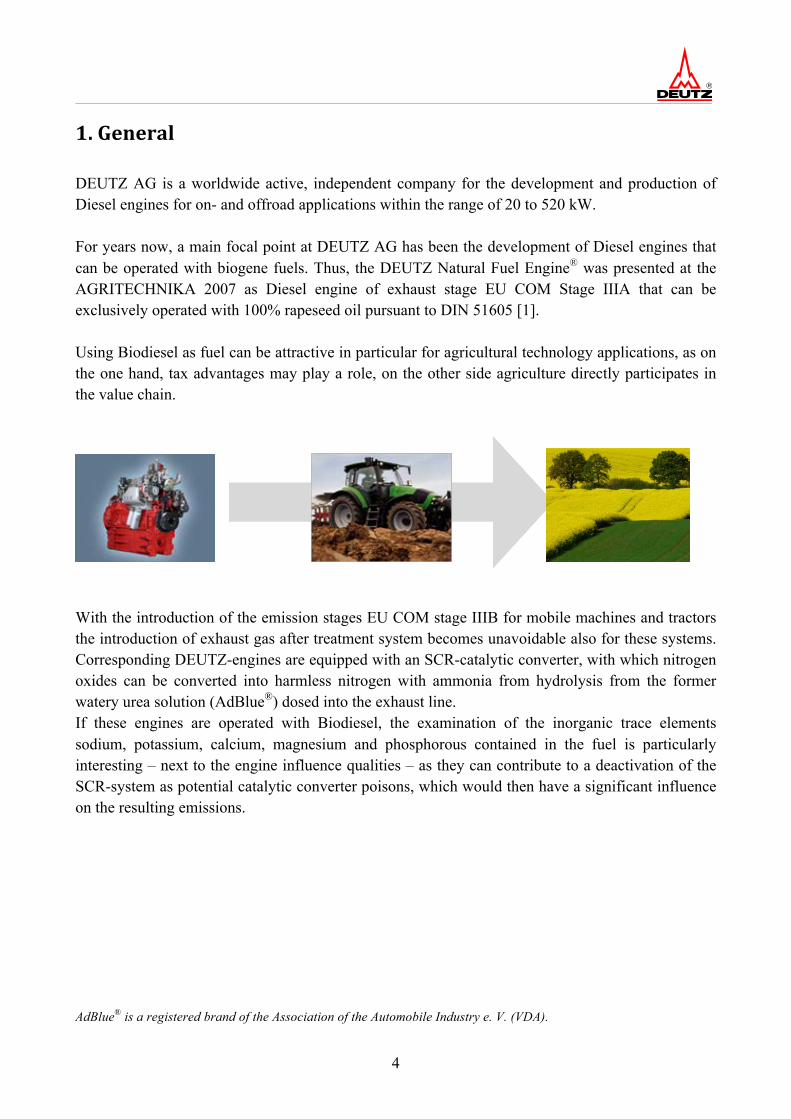
1. General DEUTZ AG is a worldwide active, independent company for the development and production of Diesel engines for on- and offroad applications within the range of 20 to 520 kW. For years now, a main focal point at DEUTZ AG has been the development of Diesel engines that can be operated with biogene fuels. Thus, the DEUTZ Natural Fuel Engine® was presented at the AGRITECHNIKA 2007 as Diesel engine of exhaust stage EU COM Stage IIIA that can be exclusively operated with 100% rapeseed oil pursuant to DIN 51605 [1]. Using Biodiesel as fuel can be attractive in particular for agricultural technology applications, as on the one hand, tax advantages may play a role, on the other side agriculture directly participates in the value chain.
With the introduction of the emission stages EU COM stage IIIB for mobile machines and tractors the introduction of exhaust gas after treatment system becomes unavoidable also for these systems. Corresponding DEUTZ-engines are equipped with an SCR-catalytic converter, with which nitrogen oxides can be converted into harmless nitrogen with ammonia from hydrolysis from the former watery urea solution (AdBlue®) dosed into the exhaust line. If these engines are operated with Biodiesel, the examination of the inorganic trace elements sodium, potassium, calcium, magnesium and phosphorous contained in the fuel is particularly interesting – next to the engine influence qualities – as they can contribute to a deactivation of the SCR-system as potential catalytic converter poisons, which would then have a significant influence on the resulting emissions. AdBlue® is a registered brand of the Association of the Automobile Industry e. V. (VDA).
5
2. Current DEUTZ-‐engine approvals for Biodiesel
In general, all DEUTZ engines are approved for the Diesel fuel/biodiesel blend permissible in Europe and the USA according to EN 590 (max. B7) [2] or ASTM D 975 (max. B5) [3]. The usage of 100 % Biodiesel (FAME) according to specification EN 14214 [4] is currently approved for the following DEUTZ engines series in mobile working machines and agricultural applications:
as of construction year 1993 and in the emission stages EU COM stage I to EU COM stage IIIA: • 912, 913, 914, 413, 513
• 1011, 2011, 1012, 2012, 1013, 2013
• TCD 2012 2V/4V and TCD 2013 2V/4V
as of construction year 2010 and in the emission stage EU COM stage IIIA: • TCD 2015
Beyond that there is an approval for the commercial vehicle engine TCD 2013 in the EURO III-, EURO IV- and EURO V-version for an addition of up to 30 % (V/V) Biodiesel according to EN 14214. This approval was the result of the project promoted by the UFOP 540/080 [5]. In the framework of a further UFOP-project (No. 530/057) the stated industrial variants TCD 2012 and TCD 2013 without exhaust gas after treatment systems were approved for operation with 100 % (V/V) Biodiesel [6]. The technical circular letter TR 0199-99-1218 extensively talks about all engine approvals for Biodiesel applications and the special framework conditions for Biodiesel usage [7].
6
3. Project presentation From literature, it is a known fact that alkaline elements like potassium and sodium can poison SCR-catalytic converters. The damaging effect is based on the fact that the acidic reaction centres in the SCR-catalytic converters can be neutralized by the alkaline effect of these elements, are thus no longer available without limitations for the SCR-reaction and the degree of effectiveness is reduced this way [8, 9, 10]. The UFOP-Project 540/080 already showed that a certain accumulation of potassium and sodium occurred in the SCR-catalytic converter after 70 000 km bus operation. However this was not yet associated with measureable catalytic converter deactivation. Even from the fact that until now, no concrete events of poisoning of SCR-catalytic converters with Biodiesel fuelling have become public it can be derived that catalytic converter poisonings do not occur in real life to the extent suggested in literature and laboratory examinations. Goal of this project was to receive more exact findings about the possible extent of the poisoning of SCR catalytic converters through Biodiesel in AGRI POWER engines as a result of the inspections: • Drive cycles and load spectrums are significantly different from commercial vehicle applications, • significantly higher fuel consumption, • significantly higher consumption of Adblue, • Common-Rail-injection systems up to 2000 bar (DCR: DEUTZ Common-Rail), • structure of the SCR-systems in the vehicle (tractor). Goal of the applied project was also the approval of engines with the cylinder capacity range of 4 to 8 litres for the European emission stage EU COM IIIB for operation with 100 %(V/V) Biodiesel pursuant to EN 14214 in order to enable agricultural customers the utilization of fiscal advantages. In detail, this includes the following engines:
• TCD 7.8 L6 and TCD 6.1 L6 with a 2000 bar DEUTZ Common-Rail-injection system
• TCD 6.1 L6 and TCD 4.1 L4 with a 2000 bar DEUTZ Common-Rail-injection system Field test inspections on three tractors of the company AGCO FENDT with approx. 1500 operating hours with FAME according to EN 14214 (Four Seasons) were defined as the range of testing:
• TCD 7.8 L6 in the FENDT X 911 (2000 bar DCR)
• TCD 6.1 L6 in the FENDT X 850 (2000 bar DCR)
• TCD 6.1 L6 in the FENDT X 711 (1600 bar DCR)
7
The approval of the basic engines without exhaust gas after treatment system can be derived from the positive experiences in the UFOP-project 540/080 in general. As however other Common-Rail-injection systems with an injection pressure of 2000 or 1600 bar are used, testing of the injection components was repeated by DEUTZ and BOSCH. Engine data (for example fuel consumption) and application types were recorded during the field tests, in order to receive information about the engine, the load spectrum and the operating conditions of the SCR-catalytic converter that is as comprehensive as possible. In addition, comprehensive fuel and lubricating oil analyses are part of the project. The fuel samples were analysed in particular regarding alkaline metals (potassium, sodium), alkaline earth elements (calcium, magnesium) and phosphorous, which may poison SCR-catalytic converters. Regarding the lubricating oil analyses, special focus is set on the wear and the Biodiesel poisoning of the engine oil. Using borderline Biodiesel regarding the elements contents was a goal in the field test. However, it became evident that such quality is not available on the market and artificial enrichment with the listed elements cannot be realised in the tank. A final Post-Mortem-Analysis of the used SCR-catalytic converters was conducted by the suppliers (Umicore AG & Co. KG). Additional literature research and data from field test inspections (for example data of AGQM and ASG Analytik Service Gesellschaft GmbH) should confirm the results. The goal of the performed inspections with positive evaluation was the approval of the listed AGRI POWER engines TCD 7.8 L6, TCD 6.1 L6 and TCD 4.1 L4 for AGRI POWER-usage and publication in the updated technical circular letter TR 0199-99-01218 „Fuels“.
8
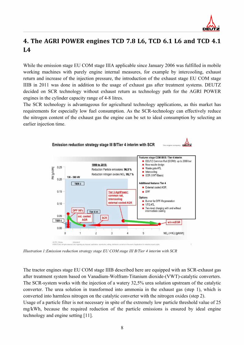
4. The AGRI POWER engines TCD 7.8 L6, TCD 6.1 L6 and TCD 4.1 L4 While the emission stage EU COM stage IIIA applicable since January 2006 was fulfilled in mobile working machines with purely engine internal measures, for example by intercooling, exhaust return and increase of the injection pressure, the introduction of the exhaust stage EU COM stage IIIB in 2011 was done in addition to the usage of exhaust gas after treatment systems. DEUTZ decided on SCR technology without exhaust return as technology path for the AGRI POWER engines in the cylinder capacity range of 4-8 litres. The SCR technology is advantageous for agricultural technology applications, as this market has requirements for especially low fuel consumption. As the SCR-technology can effectively reduce the nitrogen content of the exhaust gas the engine can be set to ideal consumption by selecting an earlier injection time.
Illustration 1:Emission reduction strategy stage EU COM stage III B/Tier 4 interim with SCR The tractor engines stage EU COM stage IIIB described here are equipped with an SCR-exhaust gas after treatment system based on Vanadium-Wolfram-Titanium dioxide-(VWT)-catalytic converters. The SCR-system works with the injection of a watery 32,5% urea solution upstream of the catalytic converter. The urea solution in transformed into ammonia in the exhaust gas (step 1), which is converted into harmless nitrogen on the catalytic converter with the nitrogen oxides (step 2). Usage of a particle filter is not necessary in spite of the extremely low particle threshold value of 25 mg/kWh, because the required reduction of the particle emissions is ensured by ideal engine technology and engine setting [11].
9
Step 1: Formation of ammonia (NH3) from urea ((NH2)2CO)
(NH2)2CO + H2O 2 NH3 + CO2 (1)
Step 2: Realisation of the nitrogen oxides (NO and NO2) with ammonia (NH3)
Illustration 3: Design TCD 7.8 L6 (Fendt X 911) with cone-SCR-catalytic converter (left/centre) and TCD 6.1 L6 (Fendt X 850/X 711) with hood-SCR-catalytic converter (right)
5. Results of the field tests All in all, three different variants were tested on the tractor types shown in illustration 3. The field tests were conducted in the period from 07/2010 to 08/2012, as the prototypes of the smaller tractor variant FENDT X711 were only available later on. The following list shows an overview of the usage profiles of the experimental engines:
Engine type TCD 7.8 L6 TCD 6.1 L6 TCD 6.1 L6 Engine number 10904092 10929831 11068457
Experimental engine Tractor FENDT X 911 Fendt-No. 944.23.0101
Tractor FENDT X 850 Fendt-No. 944.23.0101
Tractor FENDT X 711 Fendt-No. 737.21.1003
Location of testing Josef Koller, Gersthofen Sauerkrautkonserven Gillmeier, Reisbach
Josef Koller, Gersthofen Alfred Luderschmidt, Wolferstadt
Usage profile approx. 60 operating hours/week
approx. 70 operating hours/week
approx. 37 operating hours/week
Average consumption / utilisation
approx. 21.4 litres/h; approx. 37 %
approx. 21.4 litres/h; approx. 40%
approx. 18 litres/h approx. 44 %
Fuel FAME pursuant to EN 14214
Biodiesel-supplier ADM / Carl Buttner ADM / Carl Buttner TECOSOL, Ochsenfurt
TECOSOL, Ochsenfurt
Provisioning / Tank unit 1000 litres IBC 1000 litres IBC 1000 litres IBC
Utilisation types
Power take-off shaft, hydraulics, transport, empty trip, standstill, shunting work (trailer, front loader, shredders, cultivator, mower, silage trailer, plow, manure spreader, mulcher)
Power take-off shaft, hydraulics, transport, empty trip, standstill, shunting work (trailer, shredders, cultivator, roller, plow, saw, disc harrow, mulcher, stone breaker)
Front loader work (58 %) Transport (16 %) Plowing (10 %) Shrubbing (16 %)
Period field test 09/2010 – 02/2011 08/2010 – 03/2011 07/2011 – 08/2012 Total duration 1688 h 1543 h 1250 h
Table 2: Usage profiles of the experimental engines
11
The following illustrations offer a realistic impression of the usage conditions of the field test tractors (different climate conditions, environmental conditions, utilisation types).
Illustration 4: Experimental engines in the endurance test
Illustration 5: Biodiesel-pump system (1000 litres IBC), Josef Koller – Gersthofen
12
The accompaniment of the field test by employees of the DEUTZ outdoor test was of significant importance. This guaranteed that possible problems were discovered and were eliminated early on. Extensive oil and Biodiesel analyses were conducted during the field tests. In this process, the concentrations of the alkaline/earth alkaline elements potassium, sodium, calcium, magnesium and phosphorous that are relevant for a deactivation of the SCR-exhaust gas after treatment should be inspected and compared with the UFOP study published in the meantime [12]. The Biodiesel used in the field tests was supplied by the companies ADM/Carl Büttner and TECOSOL. These companies are members of the working group Quality management Biodiesel e.V. (AGQM). In its technical circular letters „Fuels“, DEUTZ AG expressly recommends ensuring the quality by purchasing Biodiesel with AGQM-certificate. 5.1 Element determinations in the Biodiesel The method of choice to determine the element contents in the Biodiesel is the procedure of the ICP OES (optical spectral analysis with inductively coupled plasma). The determination of the alkaline and earth alkaline metals was done with internal standard following the test method DIN EN 14538 [13], the phosphorous content was determined with the procedure pursuant to DIN EN 14107 [14]. The following table shows the average values of the total of 50 analyses from the DEUTZ-field tests as well as the results from the study from Wilharm and Stein [12] for the years 2010 and 2011. It shows that the quality of the Biodiesel available in field tests corresponds well with the results of the indicated study [12] regarding the element concentration. Also other quality characteristics like density, oxidation stability (≥ 6 h) and water content are within the range of the requirement standard EN 14214.
Sodium Potassium Calcium Magnesium Phosphorus in mg/kg
DEUTZ Field test 2010/2011
0.26 0.41 0.06 0.01 0.25
AGQM-Study 2010 Wilharm and Stein
0.19 0.12 0.03 0.02 0.11
AQGM-Study 2011 Wilharm and Stein
0.30 0.18 0.03 0.02 1.94
DEUTZ Field test 2012
0.17 0.23 0.22 0.07 0.39
Table 3: Trace elements in the FAME
13
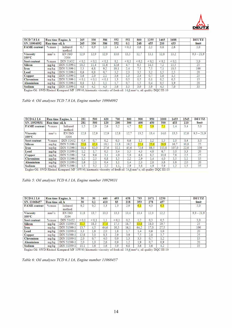
5.2 Used oil analyses of the field test engines Lubricating oil analyses were conducted on all engines in regular intervals, and all typical used oil parameters were analysed in the chemical laboratory of DEUTZ AG. The analyses were performed according to the currently recognized DIN inspection standards. The analysis values for the three experimental engines are listed in tables 4 to 6. SWD Rheinol Komparol MF 10W40 with the oil quality DEUTZ DQC III-10 was used in the field test engines as engine oil. The DEUTZ-used oil threshold values are listed in the table on the right [15]. Measurement values that exceed these values are highlighted in colour. Increased silicon percentages are found in two of the three engines mainly during the first oil change after approx. 500 operating hours (DEUTZ-threshold value: 25 mg/kg). These values are a familiar phenomenon among new engines and can be explained with so-called original dirt (cast residue, residue from mechanical processing). The increased silicon values were only found up to the first change of oil. The increased input of FAME into the engine oil is relevant for Biodiesel operation. The DEUTZ-threshold value of 5 % (V/V) Biodiesel part was partially exceeded. However, this threshold value is possibly set too low and will probably be increased in the future based on further discoveries [16]. High Biodiesel addition may result in chemical reactions and polymerisation in the engine oil with subsequent engine damage. For this reason, Biodiesel operation requires cutting the oil change intervals in half. In case of the AGRI POWER-engines described here the standard interval is halved from 500 operating hours to 250 operating hours.
14
Table 4: Oil analyses TCD 7.8 L6, Engine number 10904092
Table 5: Oil analyses TCD 6.1 L6, Engine number 10929831
Table 6: Oil analyses TCD 6.1 L6, Engine number 11068457
15
5.3 Findings of the injection system The injection systems of the three field test engines were diagnosed by the company BOSCH according to the standard specifications. In detail, the following items were inspected:
• FCU (Fuel Control Unit): function and adherence to the component specific threshold values (conveyed amount via flow); visual analysis of the individual components for wear.
• High pressure pump PF 45-XX: Function and adherence to the component specific threshold values (conveyed amount via speed, opening pressures of the In/Out valve in the PF45); condition of the components after runtime regarding wear, accumulation formation and grooves. On the TCD 7.8 L6 and TCD 6.1 L6 (2000 bar) PF45-20 were inspected, on the TCD 7.1 L6 (1600 bar) a PF45-16 was inspected.
• Rail and Rail add-on components: Pressure test or tightness test of the rail up to 2350 bar; test opening pressure pressure limit valve (DBV); function test Rail pressure sensor (RDS); visual inspection components for wear and cavitation.
• Injectors: Function and adherence to the component specific threshold values (injection quantity in defined test points and comparison with new part tolerances); visual analysis of the single components for wear, analysis of the accumulations on the injector nozzles.
The inspection of the injection systems (FIE) by DEUTZ and BOSCH showed slight irregularities. The injectors of the TCD 6.1 L6 (2000 bar) had slight accumulation in the area of the body bearing/cyl. bearing (needle), which is based on the accumulation critical elements zinc and sodium. On the TCD 7.8 L6 (2000 bar) the injectors showed increased injection quantities with lower pressures. The visual inspection of the injector components showed abrasive seat wear caused by particles. The hydraulic irregularities can be based on leaking ball bearings. All other components showed typical run marks. However, BOSCH found that the determined abrasive seat wear was not caused by the used FAME fuel, but independently by introduced particles. One possible explanation would be the silicon parts in the fuel analysed at the beginning of the permanent operation that could have been brought in by poisons of the 1000 litre containers that the customer provided. A further possibility is given due to the dusty conditions on the field during the trial experiments. However, there is no serial approval by BOSCH regarding FAME-operation, so that the risk of quality costs in possible Biodiesel operating damages in the FIE system must be assumed by DEUTZ.
16
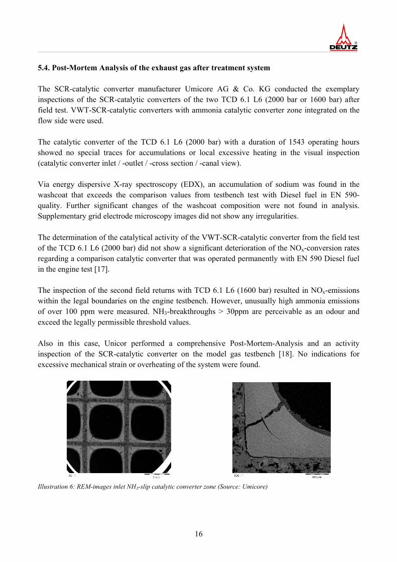
5.4. Post-Mortem Analysis of the exhaust gas after treatment system The SCR-catalytic converter manufacturer Umicore AG & Co. KG conducted the exemplary inspections of the SCR-catalytic converters of the two TCD 6.1 L6 (2000 bar or 1600 bar) after field test. VWT-SCR-catalytic converters with ammonia catalytic converter zone integrated on the flow side were used. The catalytic converter of the TCD 6.1 L6 (2000 bar) with a duration of 1543 operating hours showed no special traces for accumulations or local excessive heating in the visual inspection (catalytic converter inlet / -outlet / -cross section / -canal view). Via energy dispersive X-ray spectroscopy (EDX), an accumulation of sodium was found in the washcoat that exceeds the comparison values from testbench test with Diesel fuel in EN 590-quality. Further significant changes of the washcoat composition were not found in analysis. Supplementary grid electrode microscopy images did not show any irregularities. The determination of the catalytical activity of the VWT-SCR-catalytic converter from the field test of the TCD 6.1 L6 (2000 bar) did not show a significant deterioration of the NOx-conversion rates regarding a comparison catalytic converter that was operated permanently with EN 590 Diesel fuel in the engine test [17]. The inspection of the second field returns with TCD 6.1 L6 (1600 bar) resulted in NOx-emissions within the legal boundaries on the engine testbench. However, unusually high ammonia emissions of over 100 ppm were measured. NH3-breakthroughs > 30ppm are perceivable as an odour and exceed the legally permissible threshold values. Also in this case, Unicor performed a comprehensive Post-Mortem-Analysis and an activity inspection of the SCR-catalytic converter on the model gas testbench [18]. No indications for excessive mechanical strain or overheating of the system were found.
Illustration 6: REM-images inlet NH3-slip catalytic converter zone (Source: Umicore)
17
The recorded quantities of Al, Si, Mg and Fe are within the range to be expected for a catalytic converter with ceramic carrier and VWT-coating. None of these components show concentration gradients along the length of the catalytic converter. Similar results apply to the typical poisoning components Na, Ca, K and S. The discovered quantities of these components are within the ranges as they are found in samples of systems that are operated under comparably conditions, but with Diesel pursuant to EN 590. From all above stated elements, only sodium has a gradient with increased values in the inlet area of both parts.
Illustration 7: REM-images with EDX-Mapping of the elements sulphur (top left), calcium (top right), sodium (bottom left), phosphorus (bottom centre), potassium (bottom right) (Source: Umicore) The recorded phosphorus concentrations are significantly increased compared to standard-EN 590-operation. In particular in the inlet area of the catalytic converter on the side of the incoming flow some of them are higher than the common comparison values with EN 590 partially by factor 2. The phosphorus concentrations strongly decrease from the inlet of the catalytic converter on the side of the incoming flow to the outlet of the catalytic converter on the side of the outgoing flow. An increased accumulation of poisoning components in the area of the NH3-slip catalytic converter zone was not indicated.
18
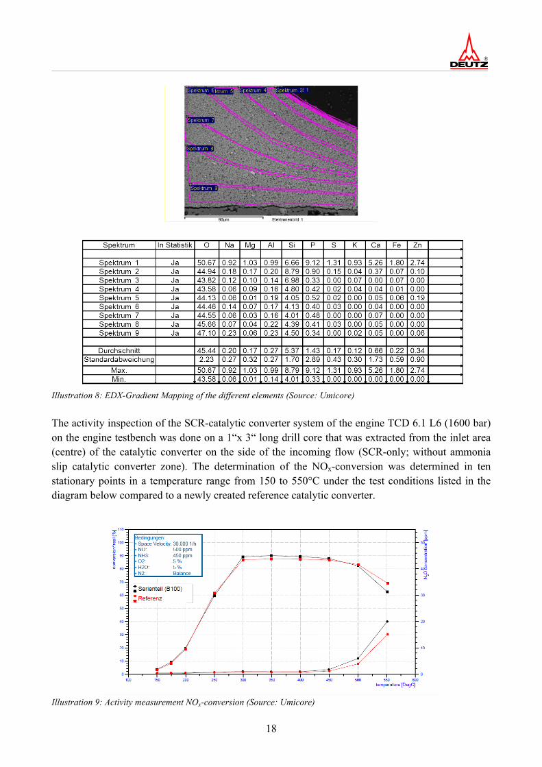
Illustration 8: EDX-Gradient Mapping of the different elements (Source: Umicore) The activity inspection of the SCR-catalytic converter system of the engine TCD 6.1 L6 (1600 bar) on the engine testbench was done on a 1“x 3“ long drill core that was extracted from the inlet area (centre) of the catalytic converter on the side of the incoming flow (SCR-only; without ammonia slip catalytic converter zone). The determination of the NOx-conversion was determined in ten stationary points in a temperature range from 150 to 550°C under the test conditions listed in the diagram below compared to a newly created reference catalytic converter.
The NOx-conversion from the field test showed only minor performance losses in the high temperature range compared to the reference. Furthermore, the activity of the ammonia slip catalytic converter zone of the SCR-systems from the field test with the TCD 6.1 L6 (1600 bar) was inspected compared to a newly created reference in the model gas. It was determined that the ammonia slip catalytic converter from the field test shows a delayed reaction behaviour in ammonia oxidation compared to a newly created reference (ΔT50(light-up) = 30 K). At the same time, it becomes evident from the determination of the formation rates of the possible secondary emissions NO, NO2, and N2O that the ammonia slip catalytic converter from the field test has an increased selectivity to nitrogen over a broader working temperature range compared to the newly created reference. In summary, it can be said that massive damages of the two inspected SCR catalytic converter systems were not discovered during the 1543 operating hours during the field test. The special influences due to ageing and contamination that are exclusively based on Biodiesel components can be classified as minor. This is rather surprising with the background of relevant literature data. 5.5. Overall evaluation of the engines No special irregularities or defects in the functionality of the engines or the exhaust gas after treatment systems occurred during the field testing that are said to be caused by using Biodiesel.
6. Calculation procedure to estimate the poisoning of the SCR-‐catalytic converter by different poisoning elements The threshold values for inorganic elements set in the European standard for Biodiesel DIN EN 14214 [4] (max. 5 mg/kg ∑ Na+K, max. 5 mg/kg ∑ Ca+Mg) are located in a range that could lead to irreversible damage of the after treatment components according to the current status of technology, if these threshold values truly mirror the Biodiesel quality found in the field today. In order to be able to provide DEUTZ-development with realistic data for the estimation of the potential frights of ash-formants and catalytic converter poisons, analysis results of market relevant Biodiesel samples from the years 2000 to 2011 were evaluated in the framework of a study [12] promoted by the Union for the promotion of oil and protein plants (UFOP). The databases of the working group Quality management Biodiesel e.V. (AGQM) and the Analytik-Service GmbH (ASG) were used as a basis. A summary of these results was published in the engine technology magazine (MTZ) [19].
20
The basis for simulating a poisoning of the SCR-catalytic converter by the elements sodium, potassium, calcium, magnesium, and zinc was given by data from poisoning experiments with the elements, which were elaborated in the framework of the FVV-projects Diesel catalytic converter deactivation I and II [8]. In the publications, the data was available in form of diagrams, whereas mmol element burden per g washcoat were used on the abscissa, and a relative SCR effectiveness standardised for uncontaminated condition was used on the ordinate (1: 100 % effectiveness, 0: 0 % effectiveness). In order to be able to calculate with the data, this was illustrated as exponential function. Relative poisoning = SCR-degree of effectiveness poisoned / SCR-degree of effectiveness not poisoned
= exp ( - Vexp * cGift) (5) with Vexp= poison exponent, cGift = Element concentration of the poison in the washcoat in mass-%. Before the equation could be applied in this form, the element concentrations had to first be converted from mmol/g to mass-%. the poison exponent was determined with a Best-Fit-Algorithm following the method of the smallest error square. The following illustration shows that the published poison data were well indicated with this mathematical approach, for the example of sodium at 350°C catalytic converter temperature, that had a poison exponent of 3.62:
Illustration 10: Poisoning of a VWT-SCR-catalytic converter (MFI) with sodium at 350°C
21
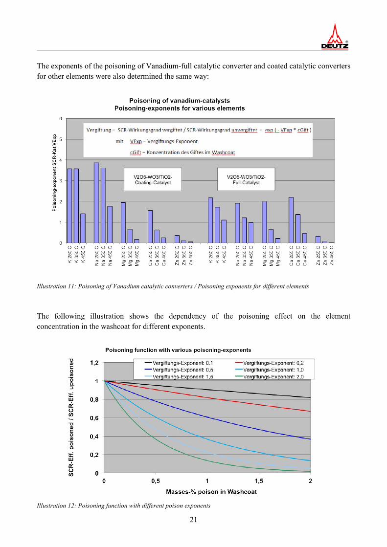
The exponents of the poisoning of Vanadium-full catalytic converter and coated catalytic converters for other elements were also determined the same way:
Illustration 11: Poisoning of Vanadium catalytic converters / Poisoning exponents for different elements The following illustration shows the dependency of the poisoning effect on the element concentration in the washcoat for different exponents.
Illustration 12: Poisoning function with different poison exponents
22
Significant poisoning effects must already be expected for elements with high poisoning potential over 1 for element concentrations of 0.1mass %. 6.1. Calculation of the element concentration in the washcoat The element emission of the engine in mg/h can be calculated from the element concentration in the fuel [mg/kg] and the fuel consumption [kg/h] (simple multiplication) and the element concentration in the lubricating oil and the oil consumption. Further multiplications with the runtime and the deposition rate (part of the emission that is retained in the catalytic converter) results in the element mass retained in the catalytic converter, from which ultimately the element concentration in the washcoat results by reference to the total washcoat mass. The deposition rate however is not known at first. It was stated in the MTZ-publication [17] as being 2,5 % , which however seems too low in retrospective consideration. 6.2. Results of the poisoning calculations The poisoning effects of the elements from lubricating oil and fuel were indicated separately, in order to be able to set the element emission caused by the additional poisoning effect by Biodiesel in relation to the element emissions caused by lubricating oil. This way it was attempted to show whether the usage of Biodiesel towards Biodiesel-free operation seems reasonable when using Vanadium-SCR-catalytic converters. The following illustration shows the result of the poisoning calculation in comparison between Biodiesel operation and Biodiesel-free operation, by setting the poisoning effect with Biodiesel-free operation to 100 %.
Illustration 13: Estimate of the poisoning effects of a VWT-SCR-coating catalytic converter at 250°C by inorganic elements from Biodiesel and lubricating oil during tractor operation (1000 h).
23
Illustration 14: Estimate of the poisoning effects of a VWT-SCR-coating catalytic converter at 250°C by inorganic elements from Biodiesel and lubricating oil during tractor operation (3000 h). The previously mentioned insecurity regarding the deposition rate has no influence on the results displayed in this graph, because it has the same effect on fuel and lubricant oil caused emissions and thus does not change the relationship. With the SCR-catalytic converter the results for the fuels with low element contents between 1000 and 3000 h are still relatively similar (slightly lower poisoning relatively to DK at 3000 h), while for borderline Biodiesel the poisoning relatively to the DK is significantly lower than at 1000 h. This is due to the fact that the poisoning with borderline Biodiesel is already nearly at 100 %. Non-linear effects are given by the fact that an active centre of the catalytic converter can only be poisoned once. If another alkaline element accumulates on the already poisoned centre this remains without influence. Further, for the calculations it was assumed that none of the poisoning elements are contained in normal Diesel without Biodiesel part. However, in field inspections that were initiated by CONCAWE (Conservation of clean air and water in Europe), a merger of the European fuel industry, traces of alkaline elements like sodium were found also in "normal" Diesel (at an average 0.1 mg/kg) [20]. Higher concentrations were also found occasionally, if for example sodium from sodium nitrite was found as anti corrosion protection additive for product transport in pipelines. If one were to include these concentrations in the simulation as well, the results would continue to align further in relative consideration.
24
6.3. Calculation of the ash accumulation in the particle filter The ash accumulation in the filter can be calculated like the ash accumulation in the washcoat, whereas only the deposition rate is set to 100 %. The ash accumulation in the DPF is not part of this project, because the SCR-engines do not have a DPF, but the calculation results are still displayed here due to the similarity of the considerations and the relevance of the DPF for future EU COM stage IV-engines.
The following illustration shows the results of these calculations:
Illustration 15: Estimate of the ash burden in a Diesel particle filter by inorganic elements from Biodiesel and lubrication oil in tractor operation (1000 h).
25
Illustration 16: Estimate of the ash burden in a Diesel particle filter by inorganic elements from Biodiesel and lubrication oil in tractor operation (3000 h). Filter loads only have linear effects, so that the relations between the fuels are independent of time. Therefore, the results regarding Diesel particle filters are identical for 1000 and 3000 operating hours. The size of particle filter is designed such that the maintenance effort by ash accumulation caused by lubrication oil is not too high (maintenance interval at least approx. 4000 h). If the ash accumulation would increase by more than double with Biodiesel operation this would no longer be acceptable.
7. Summary and outlook The engines TCD 7.8 L6 (2000 bar injection system) and TCD 6.1 L6 (2000 bar injection system) are meanwhile approved for operation with 100 % Biodiesel pursuant to EN 14214 [21]. The engines TCD 6.1 L6 (1600 bar injection system) and TCD 4.1 L4 (1600 bar injection system) are equipped with a preliminary approval due to previous experiences, which can be converted into an unlimited approval after the final inspection of the exhaust gas after treatment system at Umicore. As a special restriction for pure Biodiesel operation, halving the oil changing intervals from 500 operating hours to 250 operating hours and replacing the SCR-catalytic converter after 3000 operating hours or after 2 years is planned. All further framework conditions for using Biodiesel are published in the current technical circular letter TR 0199-99-01218 „Fuels“ [7].
26
The inspections of the SCR-exhaust gas after treatment systems show that the poisoning and deactivation of VWT-catalytic converters in real operation is lower than previously assumed. At the same time the low element concentrations of phosphorus, sodium, potassium, calcium and magnesium were confirmed to the AGQM-quality supervisions in the framework of the field testing by numerous Biodiesel analyses [22, 23, 24]. These low element concentrations are an important component for the approval of the DEUTZ-agriculture technology engines of EU COM stage IIIB. However, it must be considered that a general new evaluation of the Biodiesel approvals is required for future EU COM stage IV-engine concepts and the associated application of other exhaust gas after treatment technologies, meaning comprehensive accompanying studies and field tests must be conducted prior to a possible approval. According to current status of development, corresponding EU COM stage IV-engines of the DEUTZ AG will nearly all be equipped with exhaust gas after treatment systems, which include a catalytically activated Diesel particle filter (DPF) in flow direction of the exhaust gas, and an SCR catalytic converter with integrated ammonia slip catalytic converter. Hydrocarbons (HC) and carbon monoxides (CO) emitted from engines are converted into harmless carbon dioxide via the Diesel oxidation catalytic converter in such systems. Furthermore, at least part of the nitrogen monoxide emitted from engines is converted into nitrogen dioxide with oxygen contained in the exhaust gas. With the help of this nitrogen dioxide, soot collected in the Diesel particle filter on the side of the outflow is burned off and the filter is passively regenerated at sufficient operating temperatures. The filter also includes an oxidation catalytic function that ensures partially oxidative reformation of nitrogen dioxide when the exhaust gas passes through the filter wall. In the downstream SCR catalytic converter the reduction of the nitrogens is done by reduction with ammonia, according to the procedure described on page 9. The best nitrogen removal rates are achieved in particular under low operating temperatures (200 – 250°C) when the ratio of nitrogen dioxide to nitrogen monoxide in the exhaust gas lies prior to the SCR-catalytic converter is around 1:1. According to literature data it can be expected that operation of the engine with Biodiesel has significant influence on the functionality of such exhaust gas after treatment systems. The Diesel oxidation catalytic converter reached first in the flow sequence is subjected to the strongest burden with the poisonous elements contained in the Biodiesel. Special attention is required here by the ash generator phosphorus that may lead to the formation of a layer covering the catalytically active centres and thus may significantly reduce their accessibility for the harmful gases to be converted. Alkali and earth alkali elements form inactive alloys with the precious metals platinum and palladium contained in the Diesel oxidation catalytic converter. As a consequence, the oxidation activity towards hydrocarbon and nitrogen monoxides is lowered. Next to resulting hydrocarbon breakthroughs through the DOC a significant reduction of the nitrogen dioxide exploitation is recorded above the Diesel oxidation catalytic converter [25].
27
The reduction of the nitrogen dioxide exploitation above the DOC indicates a possibly massive deterioration of the passive regeneration behavior of the downstream Diesel particle filter, as the passive soot combustion happens using NO2 [26, 27]. More frequent active regeneration measures or standstill regenerations and an associated higher thermal burden over the lifespan and faster thermal ageing of the filter would be the consequence. Furthermore, significantly higher ash burdens of the particle filter were recorded in Biodiesel operation [28]. The catalytic converter coating in the catalytically activated filter generally fulfils two functions. For one, it provides the oxidative realisation of the secondary emissions (HC, CO) occurring during soot combustion under non-ideal operating conditions. On the other hand nitrogen dioxide is generated over this coating, which was used up before in soot combustion. In general, the identical influences can be expected for the poison susceptibility of this oxidation catalytic coating as for the Diesel oxidation catalytic converter, whereas degradation of the oxidation activity of this coating will probably occur slower than the poisoning of the upstream Diesel oxidation catalytic converter, as the DOC will already "catch" a significant amount of the poisonous components contained in the exhaust gas. Most probably, the lowest accumulation of poisonous components from Biodiesel can be expected in the SCR system on the outlet side. However, apart from that an expected damage of the DOC/DPF pre-system will have a significant influence on the functionality of the SCR system. As described the highest nitrogen removal rates are achieved in particular in the temperature range up to 300°C if the NO2/NOx-ratio fed into the SCR catalytic converter lies at approx. 0.5. Due to the poisoning of the pre-system to be expected it is questionable whether corresponding NO2/NOx-ratios in the exhaust gas prior to the SCR-catalytic converter can be ensured. Further, in particular SCR-technologies based on medium porous zeolithe have an increased poisoning susceptibility towards hydrocarbons. If these are not fully oxidised to harmless carbon dioxide in the pre-system the risk that they are collected in the low temperature range in the zeolithe structure is given. A rapid increase of temperature in the SCR catalytic converter, as by all means may occur in dynamic operation can then initiate the oxidative combustion of these accumulated hydrocarbons. This may lead to the formation of local exothermes in the SCR catalytic converter that may cause irreversible damage of the SCR catalytic converter. The complexity of the cause-effect-relationships in such an exhaust gas after treatment system prevents the transfer of current approvals achieved on EU COM IIIB engines to successive engines with Biodiesel operation. Elaborate inspections concerning system poisoning behaviour on the engine testbench as well as in field tests seem urgently necessary. In every case the Biodiesel industry is also required to continue increasing its quality standards in particular regarding the above stated trace elements. This also includes the extensive reduction of the threshold values prescribed in EN 14214 for alkali and earth alkali elements as well as an adaptation of the test procedures that are currently performed on a European level (CEN) [29].
28
Index of literature [1] DIN 51605 (September 2010): Kraftstoffe für pflanzenöltaugliche Motoren – Rapsölkraftstoff – Anforderungen und Prüfverfahren. Beuth Verlag, Berlin [2] DIN EN 590 (Mai 2010): Kraftstoffe für Kraftfahrzeuge – Dieselkraftstoff – Anforderungen und Prüfverfahren. Beuth Verlag, Berlin [3] ASTM D 975 (2011): Standard Specification for Diesel Fuel Oils. ASTM International [4] DIN EN 14214 (April 2010): Kraftstoffe für Kraftfahrzeuge – Fettsäure-Methylester (FAME) für Dieselmotoren – Anforderungen und Prüfverfahren. Beuth Verlag, Berlin [5] H.W. Knuth, M. Winkler (2009): Durchführung eines Prüfstands-Dauerlaufs über 500 h sowie Feldtesterprobung zur Freigabe von DEUTZ-Common-Rail-Motoren in Nutzfahrzeugen EURO IV für Biodiesel. UFOP-Projekt 540/080 [6] A. Rill (2006): Anpassung eines Dieselmotors auf den optionalen Betrieb mit Rapsöl-Methylester. Diplomarbeit, Fachhochschule Frankfurt/Main (Januar 2006) im Rahmen des UFOP-Projekts 530/057 (500 Bh Freigabe-Dauerlauf TCD 2012 L06 4V Stufe EU COM IIIA) [7] Technical circular 0199-99-01218 (2012): „Fuels“. DEUTZ Documentation [8] P. Kern, M. Klimczak, M. Lucas (2009): Dieselkatalysatordesaktivierung I + II. FVV-Abschlussbericht Nr. 878, Frankfurt [9] M. Klimczak et al (2010): High-throughput study of the effects of inorganic additives and poisons on NH3-SCR catalysts – Part I: V2O5–WO3/TiO2 catalysts Applied Catalysis B: Environmental 95, pages 39–47 [10] Xiaoyu Guo (2006): Poisoning and sulfation on vanadia SCR catalyst. Brigham Young University [11] P. Broll, S. Schraml (2009): Zukünftige Abgasnachbehandlungssysteme für Off-Road-Anwendungen. 8. Dresdener Motorenkolloquium [12] T. Wilharm; H. Stein (2011): Kurzstudie zur Evaluierung der Metall-, Phosphor- und Schwefelgehalte in Biodiesel, UFOP-Projekt Nr.540/104 [13] DIN EN 14538 (September 2006): Erzeugnisse aus pflanzlichen und tierischen Fetten und Ölen – Fettsäure-Methylester (FAME) – Bestimmung des Ca-, K-, Mg- und Na-Gehaltes durch optische Emissionsspektralanalyse mit induktiv gekoppeltem Plasma (ICP). Beuth Verlag, Berlin
29
[14] DIN EN 14107 (Oktober 2003): Erzeugnisse aus pflanzlichen und tierischen Fetten und Ölen –Fettsäure-Methylester (FAME) – Bestimmung des Phosphorgehaltes durch Emissions-spektrometrie mit induktiv gekoppeltem Plasma (ICP). Beuth Verlag, Berlin [15] Technical circular 0199-99-01187 (2012): „Used oil limit values”. DEUTZ Documentation, 3rd issue [16] V. Wichmann, E. Flügge, U. Schümann, S. Berndt (2011): Schmierölstabilität I – Betriebsverhalten von Schmieröl im Pflanzenöl- und Biodieselbetrieb. FVV-Abschlussbericht 934-2011, Frankfurt/Main [17] Post-Mortem-Report Fa. Umicore, SCR-Kat. TCD 6.1 L6 (MN. 10929831 bar) Feldrückläufer vom 11.11.2011 [18] Post-Mortem-Report Fa. Umicore, SCR-Kat. TCD 6.1 L6 (MN.11068456) Feldrückläufer vom 06.06.2013 [19] H.W. Knuth, H. Stein, T. Wilharm, M. Winkler (2012): Element pollution of exhaust aftertreatment systems by using Biodiesel. MTZ, 73.Jahrgang (Ausgabe 06/12), Springer/Vieweg-Verlag, Wiesbaden. [20] CEN/TC 19/WG 24/N 371 (Oktober 2012): Automotive fuels – High FAME (B11 - B30) diesel fuel blends – Background to the parameters required and their respective limits and determination . [21] Pressemitteilung der DEUTZ AG am 16.05.2012: „DEUTZ gibt Motoren für Betrieb mit Biodiesel frei.“ [22] Biodiesel in Deutschland – Die AGQM-Herstellerbeprobung 2010. http://www.agqm-biodiesel.de/de/aktuelles/pressearchiv/agqm-veroeffentlicht-studie-ueber-qualitaet-von-biodiesel/ (Date 12.04.2013) [23] Biodiesel in Deutschland – Die AGQM-Herstellerbeprobung 2011. http://www.agqm-biodiesel.de/de/aktuelles/pressemeldungen/agqm-veroeffentlicht-qualitaetsbericht-biodiesel-2011/ (Stand 12.04.2013) [24] Biodiesel in Deutschland – Die AGQM-Herstellerbeprobung 2012. http://www.agqm-biodiesel.de/de/aktuelles/pressemeldungen/biodiesel-qualitaet-der-agqm-mi/ (Date 12.04.2013) [25] A. Williams, R. McCormick, J. Luecke, A. Zimmermann, K. Voss, K. Hallstrom, M. Leustek, J. Parsons, H. Abi-Akar (2011): SAE Int. 01, 1136
30
[26] B.J. Cooper, H.J. Jung, J.E. Thoss: Europäische Patentanmeldung 0 341 832 [27] A. Andreasson, G.R. Chandler, C.F. Goersmann, J.P. Warren: Europäische Patentanmeldung 1 054 722 [28] Aaron Williams, National Renewable Energy Laboratory, 05/14/2012 [29] M. Winkler, S.H. Kägler, D. Wüstkamp (2012): Trace elements in fuels – a status report. Erdöl, Erdgas, Kohle. URBAN-VERLAG, Hamburg/Wien (128. Jahrgang, Heft 10)