31
lf,< LONG WAVELENGTH INFRARED FIBER OPTICS /,NTT AM ENGMlEERINGREPORT 1 September 1064 0'.- 'P D- c !O , ?McRA A' : !?e :-: ! !9
lf,<
LONG WAVELENGTH INFRARED FIBER OPTICS
/,NTT AM ENGMlEERINGREPORT 1
September 1064
0'.- 'P D- c
!O ,
?McRA
A'
: !?e :-: ! !9

NOTICES
When Government drawings, specifications, or other data are used forany purpose other than in connection with a definitely related Governmentprocurement operation, the United States Government thereby incurs noresponsibility nor any obligation whatsoever; and the fact that the Govern-ment may have formulated, furnished, or in any way supplied the said draw-ings, specifications, or other data, is not to be regarded by implication orotherwise as in any manner licensing the holder or any other person orcorporation, or conveying any rights or permission to manufacture, use,or sell any patented invention that may in any way be related thereto.

ii
LONG WAVELENGTH INFRARED FIBER OPTICS
/INTERIM ENGINEERING REPORT 1
(1 September 1964
0 -- p
Prepared for 36
[Air Force Avionics LaboratoryResearch and Technology Division
Air Force Systems CommandWright-Patterson Air Force Base, Ohio
Under
Contract No. AF 33(615)-1952Project No. 4056, Task No. 405603
LSubmitted by
Optics Technology, Inc.248 Harbor Boulevard
Belmont, California

TFOREWORD
This report was prepared by Optics Technology, Inc., Belmont, California,
on Air Force Contract AF 33(615)-1952 under Task No. 405603 of Project No. 4056,
"Long Wavelength Infrarud Fiber Optics." The work was administered under the
I direction of the Air Force Avionics Laboratory, Research and Technology Division,
Air Force Systems Command. Mr. A. Prettyman was project engineer for the
I Laboratory during the first quarter of the program.
This report covers the work performed from June 15 to September 15, 1964
and is the first interim engineering report on the program.I-Personnel who have contributed to the program during this period include
N. S. Kapany, principal investigator, and R. J. Simms.
FF
I
1~
I
I
I-I
ABSTRACT
Work on the development of "Long Wavelength Infrared Fiber Optics"
under Contract No. AF 33(615)-1952 during the first quarter is reported. The
results of a literature survey for glasses with longer wavelength infrared trans-
mission than arsenic-sulphur glasses are described in detail. The conclusions of
this survey are discussed and samples have been obtained of some of the selected
glasses. The equipment necessary for this program is described and progress
on its fabrication reported.
Preliminary attempts to draw fibers with the available samples using
existing fiber drawing equipment have indicated that closer environmental control
is necessary to produce seed-free fibers. This was anticipated, and new equipment
is now being built. The second quarter will see the completion of all the required
equipment and initial work on fiber drawing under more sophisticated conditions.
Publication of this report does not constitute Air Force approval of the
report's findings or conclusions. It is published only for the exchange and
stimulation of ideas.
iii

TABLE OF CONTENTS
I. INTRODUCTION 1
I. TECHNICAL DISCUSSION 3
A. Literature Survey 3
B. Fiber Drawing Equipment 5
C. Optical Equipment 6
D. Fiber Drawing Experiments 9
III. FUTURE PLANS 13
APPENDIX 15
v

I. INTRODUCTION
The program for the development of "Long Wavelength Infrared Fiber Optics"
is a logical extension of a previous program undertaken by Optics Technology, Inc.,
entitled "Infrared Fiber Optics Investigation". Under the previous program the
techniques for fabricating fiber optics devices from the arsenic-sulphur glasses for
use over the wavelength range 1 to 12 microns were developed. The current program
has as its aim the extension of the wavelength range of fiber optics to cover, as a
minimum, the 8 to 14 micron range. The end result of the program will be the
production of fiber optics components for use through the atmospheric window at
8 to 14 microns with an intended overall infrared transmission range of 1 to 18
microns. This program will open a new wavelength range with consequent new
aprlic" "-rns for fiber optics.
The first quarter has been spent on the following:
1. A survey of both classified and unclassified literature and of all other
relevant sources to establish data on glasses which transmit at wavelengths beyond
the limit of the arsenic-sulphur glass. The survey was followed by a selection of
those relevant glasses potentially suitable for the fiber optics technologies.
2. Contact was made with the organizations which have produced these
selected glasses, samples and quotations were requested and in two instances orders
have been placed for specific glasses. Correspondence has also been initiated
with alternative sources who either could contribute to the technical understanding
of the properties of glasses that transmit in the required ranges or who may be
future suppliers of glass.
1

3. Several pieces of equipment for use in this program were designed and
their fabrication initiated. The mechanical work on the fiber drawing machine is
complete; one of the two furnaces is installed ard work is beginning on wiring the
power supplies and associated electronics. A concentric crucible furnace is being
constructed for the production of flexible fibers and will be used with existing fiber
winding machinery. It is hoped that this furnace will provide the design information
or will itself be used in the second furnace in the fiber drawing machire ?nder
construction.
A motorized goniophotometer table has been constructed and will be used
to record the radiation patterns and measure the spectral transmission of fiber
optics components. The design of an optical condenser for recording spectral
transmission profiles has been finalized and construction of the condenser will
begin in the near future.
4. Attempts have been made to draw coated fibers from several glass
combinations using the samples of far infrared transmissing glasses supplied by
the sponsor at the beginning of this program. The. results of these experiments are
discussed later in detail.
2

II. TECHNICAL DISCUSSION
A. Literature Survey
Relatively few workers have been, or are, active in the area of long
wavelength infrared transmitting glasses and it was clear during the literature
survey that the copious cross referencing used by individual authors encompassed
the majority of the literature on this subject. Abstracts, indices and contents of
* all potentially relevant journals and sources were searched for references
concerned with the properties of non-oxide vitreous systems. A Russian group
headed by Kolomiets has contributed several papers on the semi-conducting
properties of these glass forming systems and, although the optical properties were
qualitatively reported, not much of the information was relevant.
The pertinent oiganizations that have been concerned with these glasses are
the following:
1. Servo Corporation of America, Hicksville, Long Island, New York;
2. Texas Instruments, Dallas Texas;
3. Royal Radar Establishment, Malvern, England;
4. IBM, Oswego, New York;
5. Jena Glaswerk Schott, Mainz, Germany;
6. Central Electricity Research Laboratory, Leatherhead, England;
7. RCA Laboratories, Princeton, New Jersey;
8. Bell Telephone Laboratories, Murray Hill, New Jersey;
9. Baker and Adamson, New York, New York;
10. A. 0. Smith Corporation. Milwaukee, Wisconsin.
3

The major portion of the literature relevant to non-oxide vitreous systems
has originated from these sources and it was clear that the field of interest fell
into two separate areas, The first, which was less relevant to this program, was
an interest in their use for encapsulating electronic components, and little data was
reported on their infrared transmitting properties. The other category was more
directly concerned with the optical properties of these glasses. Sources 4, 7 and 8
fall in the former category, 9 and 10 are no longer active in this field and the rest
have done more relevant work.
Twenty-three major gIlass forming systems are reported in the literature
concerned with infrared transmission which exhibit substantial infrared transmission
at wavelengths greater than the longest presently obtainable with oxide glass forming
systems. These are individually examined in the appendix, in which the more
prom si1g iiystems are selected and the problems relevant to each and the action
being taken are discussedl in detail. The sources which can most readily supply
glasses which are considered to be potentially usable for this work are Servo
Corporation and Texa; Instruments; quotations have been requested for individual
glasses from both comprllies. Prior to submitting these requests for quotation, a
trip was taken to bc2h companies to discuss the properties and problems of the
respective glasses, and valuable information beyond that published in the reports
was obtained. Some samples of the Servo glasses were available from Wright-
.Patt6rson Air Force l:a. early in the program and these have been used for rial
fiber draws wlch will be dscussd later. As a result of quotations two glasses
(62-73]3 and 62-75 B) have been ordered from Servo. Two glasses (Melt Numbers
4

165 and 177) of the germanium-arsenic-tellurium glass have been ordered and
received from Texas Instruments. The action taken with respect to alternative
supplies and different glass types and the expected results are discussed in the
appendix.
B. Fiber Drawing Equipment
The major equipment being constructed for this program is a double
furnace fiber drawing machine. This machine has one furnace for drawing single
fibers from concentric crucibles and a second furnace for drawing multiple fibers
from a multiple fiber assembly, and both are incorporated in a single frame with a
single bank if temperature controllers to coptrol whichever furnace is in operation.
This fiber drawing machine contains the results of the experience gained during the
previous program and of the wide experience at Optics Technology, Inc. in
fabricating drawing machines for a variety of uses. Since the design of the concentric
crucible side of the furnace has not been finalized, a description of this machine
will be given in a later report.
In addition to this machine the construction of a concentric crucible furnace
is underway. The crucibles will be heated by flexible heating tapes tC enable more
precise temperature control of the different sections of the furnace and internal
inspection can be made during the drawing process through an outer, thick glass
wall. Initially, this furnace will be mounted in an existing flexible fiber drawing
rig and evaluated with the arsenic.-sulphur glasses already available at Optics
Technology. This procedure will also be used with the new crucible designs since
the properties of the arsenic-sulphur glasses are well known thus limiting the
5

uncertainties to the crucible rather than to the glass. This flexible fiber drawing
furnace will either be used in the fiber drawing machine, if it proves suitable, or
will form the basis for the design of a suitable furnace for this machine.
Several small concentric crucibles were made during this quarter and have
been used with samples of the Servo glasses available at the start of this program
for the production of coated fibers. These crucibles were used in the furnace which
proved suitable for the arsenic-sulphur glasses but the problems peculiar to the
longer wavelength transmitting glasses prevented the production of high quality
fibers.
C. Optical Equipment
The optical evaluation of the fibers and fiber optical components during this
program will be based on techniques developed during the previous year. A new
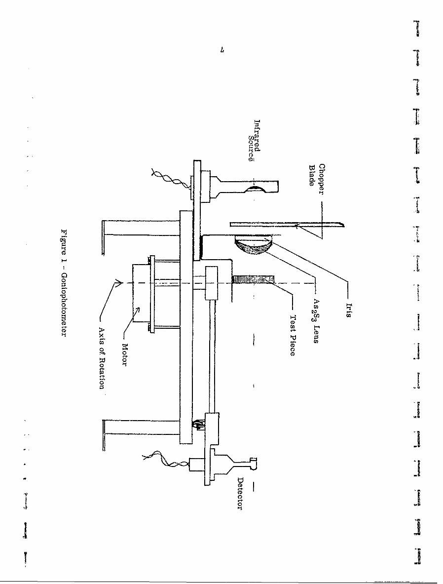
goniophotometer table has been constructed for use on the existing equipment and
is now ready for the evaluation of suitable samples. This table is motorized and
is designed to minimize stray light problems, so that the results should be both
more accurately and more quickly recorded than with the previous goniophotometer.
Figure 1 shows a diagram of the new attachment.
The optical evaluation equipment is based around a Perkin-Elmer Model 13
Spectrophotometer. This spectrophotometer was overhauled at the beginning of the
program. The delivery of a KBr prism, to extend the range beyond the 14 micron
limit of the present NaCl prism, is now being awaited.
The basic spectrophotometer was used to record the spectral transmission
of the three bulk samples of Servo glass, the results of which are shown in Figure 2.
6
i
oco
ctpt
0 00
0T
t'
-Di
1 1'Y a

S
Per Cent Transmission -'
-Co
4N
" II I" I I
c-, 0
x N
(D0 x
ii
0DM
//1 /
co II
'-- I
t--*-/D
Go / (n,~ w, 80
oeiD~ID'C

There are instrumental uncertainties in the recording of these transmission curves
since the samples were of high refractive index material 0.4 inch thick. This
causes serious defocusing in the sample beam without compensating, equally, the
reference beam of the instrument. Sample 62-91B shows evidence of microscopic
bubbles which might explain the overall decrease in transmission, but the absence
of a 12.7 nic con absorption in this glass is not adequately understood. It is
considered that this sample may have been an experimental one to eliminate the
presence of As20 3 . Consequently the overall spectral transmission figures must
be regardet' as the minimum, and in practice may be a little greater than recorded.
This wilL be confirmed with the radiation pattern recording equipment. It is
noteworthy that the samples ordered from Servo Corporation will be processed to
minimize the 12.7 micron absorption and should show the higher transmission
values of Figure 2 with transparency in the 13 micron region.
D. Fiber Drawing Experiments
The small samples of Servo glasses 62-73B, 62-77B and 62-91B were
obtained from the sponsor early in this program. It was anticipated that more
careful environmental control was required in the drawing of these gi .sses than
previously provided for the arsenic-sulphur glasses but it was considered valuable
to proceed with fiber drawing experiments without this additional provision. The
following combinations of glasses were used in these experiments:
Coating Glass Core Glass
62-73 B 62-77 B62-91B 62-77 B
Preliminary experiments were conducted with the arsenic-sulphur glasses. The
9

results showed that the core glass did not flow as readily from the nozzle as the
coating glass. This was attributed to the fact that the two cru'2ibles, being
approximately one quarter cf the height of the crucibles used during th6 previous
year, were constrained to be too close in temperature. With the larger crucibles,
which were used earlier with success, the upper crucible was maintained about
1000F hotter than the lower crucible to provide the viscosity differences necessary
to bring the core glass down the longer nozzle tube and maintain reasonable fiber
core to coat ratios. The nozzles were redesigned before the arsenic-seenitum-
tellurium glasses were used so that the constriction through which the coating glass
would flow was proportionately narrower. The three samples of arsenic-selenium-
tellurium glass used in this work %ere not optimally chosen for core-coat
compatibility and the differences in softening point proved to be greater than could
be tolerated with the small compact crucible design. In this c-rucible design the
temperatures in the core and coating glass reservoirs are equal (see Figure 3).
Another factor which is of importance in the results obtained in this work is the
short distance between core glass reservoir and nozzle, resulting in low hydr-
static pressure at the nozzle. This hydrostatic pressure is important when the
crucible nozzles are heated, since it ensures that the glass descends in a solid
plug which replaces all the air in the nozzle.
The most important observation in this preliminary work was the existence
of many seeds in the drawn fibers, These seeds were oxidation particles which
had occurred either at the surface of the reservoir melt, on the surface of each
piece of cullet as it was melted at the beginning of the operation, or within the
10
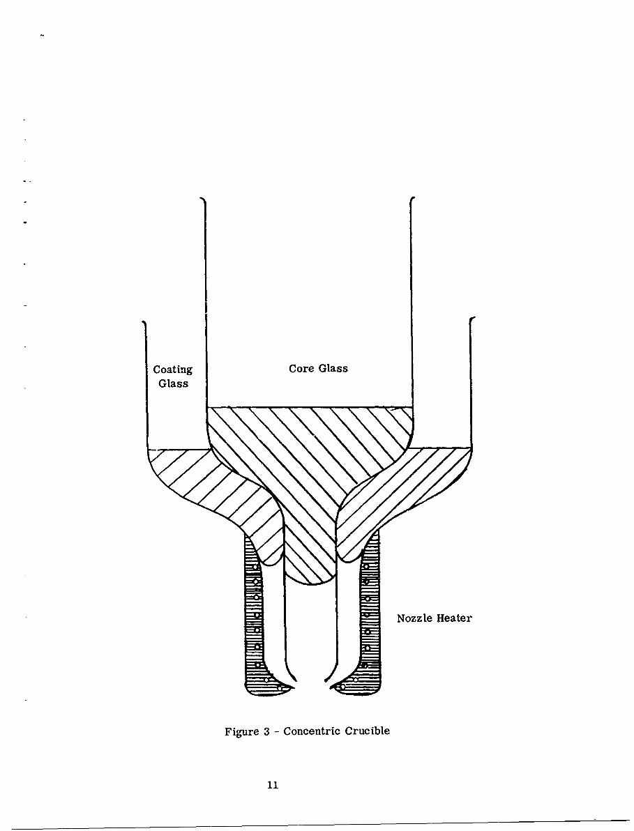
Coating Core GlassGlass
Nozzle Heater
Figure 3 - Concentric Crucible
11

nozzle itself before the glass had reached the lower end of the down tubes. Melts
62-73 B and 62-77B both drew into fine, flexible, comparatively strong fibers and
it is anticipated that the vitrification problems will not therefore be serious.
However with glass 62-91B, after severe thermal cycling, devitrification occurred
in substantial portions of the reservoir in the crucible. information is awaited from
Servo regarding this phenomenon since it may limit the utility of this particular glass
in the fiber optics processes.
It may be concluded from this work that the temperatures of the two crucibles
must be independent and that careful atmospheric control is of the utmost importance.
Consequently the first, larger crucible to be constructed will have separate heating
tapes for each half of the crucible, together with a third nozzle heater, each of
which will be controlled by a separate temperature regulator. The crucibles will
be mounted inside a glass bell jar in which a slight positive pressure of pure
nitrogen will be maintained. A controlled flow of nitrogen will be directed from
the bell jar into the nozzle area in an attempt to prevent oxidation within the
nozzles. The results of future woi k in which this technique will be used will be
reported as they become available.
12

IlI. FUTURE PLANS
The fiber drawing machine, the optical evaluation equipment and the first
fiber production crucible will be completed within the next month. The glass
samples from the Servo Corporation should arrive in two weeks, at which time the
evaluation of these materials for their fiber optics drawing properties under
suitably controlled conditions will be initiated. These evaluations should be
completed during the next quarter and final decisions will be made on two or
three glass combinations to be used during the remainder of this program. The
.- ~- optical evaluation equipment will be used to record data on thick bulk glass
samples as well as on fiber samples as they become available.
13

r
I
ftAPPENDIX
FFAR INFRARED FIBER OPTICS MATERIALS SURVEY
TIrI
FFVF'FFI.II1 15
APPENDLX
kU) FAR INFRARED FIBER OPTICS MATERIALS SURVEY
The properties of the As-S series of glasses are well known and have been
widely reported. The infrared glasses considered in this survey must primarily
satisfy the criterion of a longer infrared transmission range than these As-S
series.
Oxide glasses have not been considered for this work since none of these
is known to transmit to 7 microns even in very thin sections. In thicknesses of
over 1 cm, few exhibit low absorption in the 2.7 to 6 micron range.
The discussions of the many non-oxide glass forming systems are derived
from a variety of sources and, consequently, though some of the conclusions will
be quantitative, some will only be qualitative. In addition to this, the techniques
of preparing the glass samples and of recording the spectral transmission are by
no means standard and the consequent variations between different sources for
data on the same samples preclude serious quantitative conclusions.
Another feature of the transmission curves of these developmental glasses
is the apparent effect of scattering, both of the Rayleigh and Mie type, which
reduces the measured transmission. Whether this is in fact scattering, and if it
is, whether the causes can be eliminated by more sophisticated preparation
techniques, are not disc! -sed in the majority of cases,
1. As-S (Ref t;;' es 1 and 2) - These glasses were used in Reference 1
and are the bazsis f.-:.in which improvements are to be made in this program,
2. (R-: (deference 3 and 4) - This glass has the same order of transmission
17

range as the As-S glasses. It is of no use beyond 11 microns, with strong indications
of high reflectance and scattering effects at shorter wavelengths. Reference 4
shows the absorption coefficients of Ge 2 S3which are in excess of 10 cm - 1 at 12
microns and beyond. Below 11 microns, the coefficients are low.
3. As-S-Cl/Br/I (References 5 and 6) - Reference 5 gives detailed data
on these glasses. They exhibit an absorption at 8 microns in common with As-S
glasses and, between 8 and 14 microns, the general transmission profile is
comparable to that for As 2 S3 . Although minor differences exist, notably in the
positions of the absorption bands, it is evident that the glasses will be of negligibly
better optical quality than As 2 S3 when used with pa,,.th lengths of 1cm or more. The
absorption coefficient of these glasses is quoted to be about 20 cm - 1 at 12 microns
and) from the curves, it is not less than 5 cm - 1 at wavelengths of more than 8 microns.
Reference 6 shows more data on the As-,S-Br glass but, since thisi is shown
qualitatively for a sample thickness of only 1 mm, it is of little value for this study.
4. As-S-Sb (Reference 7) - The transmission zurves of this reference are
somewhat diagrammatic and are for sample .hicknesses of less than 2 mm. This
glass shows increasing absorption from 9 microns onward which is to be anticipated
from the presence of the As-S bonding.
5. As-S-Te (Reference 7) - The comments for the preceding glass apply
to this one also.
6. Ge-P-S (Reference 4) -. The absorption coefficients for these glasses
are well above 10cm - 1 over the wavelength range 8 to 14 microns so are patently
not suitable. As the phosphorus content approaches zero, (c.f. comments on
Ge 2 S3 ) the transmission range extends, A further problem with glasses that
18
contain phosphorus is that the presence of free phosphorus renders the glasses
chemically unstable.
7. Se (References 3 and 8) - Selenium exists in an amorphous form up to
35 0 C at which temperature It melts. Although the infrared transmission is good
(CC less than 0.5 cm - 1 ) to beyond 20 microns with the exceptior, of small bands at
13.5 and 20.5 microns, the low softening point precludes its use in this work in
environments of up to 1000C.
8. Ge-Se (References 9and 3) - Reference 3 shows two glasses from this
system to be, in 2"rnm thicknesses, absorption free over the range 3 to 15 microns
except for a moderate absorption at 13 microns. They postulate that this is the
13.6 micron band of Se shifted by the addition of Ge. Reference 9 also deseribes
these glasses but allocates an absorption coefficient of up to 20cm.71 at 13
microns and above 5 cm - 1 at longer wavelengths. Reference 3 postulates that
the 13 micron band may be accentuated by the presence of Gc0 2 which does
absorb at this wavelength. This is partly supported by the work on the As-Se-Ge
system which will be described below.
9. Ge-Se-TI/Sb/Bi (Reference 3) - The results of these glasses, all
with less than 5 per cent of the third co.stituent, are close to those for the Ge-Se
system. Worthy of note is the reported near absence of the 13 micron band for
a 1.8mm thickness of Ge-Se-Tl whicb become. excessively strong on the addition
of 0.025 per cent 02.
10. As-Se,As-Se-Te (References P and 11) - The As-Se glasses are special
cases of the three component sy ,c m As-Se-Te Reference 10 gives the greatest
19
detail on this system and the conclusions are largely confirmed by other
investigations. The glasses generally are absorption free from 3 to 12 microns.
A narrow band is centered at 12 7 and a wide one at 16 microns.
If the 12.7 band could be eliminated, some of the glasses should have
absorption coefficients of less than 0.5 cm - 1 over the range 2 to 13+ microns.
Reference 10 reports work aimed at eliminating the 12.7 micron baud and, attribute it to
As203, This last assumption is justified and is supported by References 3 and
11. The As-Se glasses appear to lose the 12.7 band more readily than the
As-Se-Te glasses, two of which are reported in Reference 10 which show no
band structure from 2 to 15 microns.
The glasses described in this reference appear to possess a uniform
absorption coefficient which varies very little over the range 2 to 15 microns.
This non-dependence of the absorption coefficient on wavelength over 3 octaves
strongly suggests scattering effects or inaccuracies in the transmission and
reflection measurements--hopefully the latter,
11. As-S-Se (References 10and I1),As-S-Se-Tl (Reference 7), As-S-Se-Te
(Reference 12) - All these grasses show transmission characteristics between
those for As-S and As-Se as would be predicted. The As-Se glasses that do not
contain sulphur are, in general, more suitable than these.
12. As-S-TI -- Reference 13 gives great detail on the optical evaluation
of this glass. The introduction to tl.Ls article describes the glass as "optically
clear frcm I to 23 microns in wavelength", However, on closer examination, it
is seen that they really mean that the absorption coefficient is at least 10cm - 1
up to 10 microns beyond which it rises rapidly'
20

13. As-Se-Te-Cu/Ag/Sb/Cd/Bi (Reference 10) - The last two are not
stable glasses and the other three are nowhere as transmissive as the base glasses
As-Se and As-Se-Te.
14. As-Sb-Se (Reference 7) - This reference, using thin samples, claims
that this glass gives good transmission of over 70 per cent from 2 to 18 microns
with a single absorption at 13 microns. Although the data may be partially
suspect, this could be of interest.
15. As-Se.-TI (Reference 7) - Absorptions up to 6 microns with fair
transmission from 6 to 18 microns. No deep absorptions are evident in the latter
range, but the transmission curve is not flat which implies some absorption.
16. Ge-As-Se (References 3 and 10) - Both the Ge-Se and As-Se systems
produce glasses which possess only one absorption, that at 12 to 14 microns. The
combination of these two binary systems results in a strong absorption at 12 to
14 microns and a weak one at 8. Reference 10 demonstrates that the 8 micron
band can be reduced to negligible proportions in a 2mm path length but the 12 to
14 band, though itcanbe diminished, couldnotbe eliminated. GeO 2 absorbs at 8 and
12 to 14 microns and As 2 0 3 absorbs at 13 microns. It is reasonable to assume
that the absorptions in the Ge-As-Se glass are primarily due to these oxides
together with a fundamental absorption at 13 microns (c.f. Se).
17. Ge-As-Te (Reference 4) - One glass shown in this reference has a
curve similar to the above but with the absorption narrowed and centered between
13 and 14 microns; otherwise, it is clear from 3 to i8 microns. Two similar
glasses show absorption coefficients which are never lower than lcm- 1 . These
latter show a strong wavelength dependence which is reminiscent of Rayleigh
21

scattering. These latter glasses also show absorption peaks at 11 microns, and
one of them at 6 microns. Clearly the data here is not self consistent- All that
can be deduced is that there is an absorption at 13 microns and the absorption
coefficient is probably less than 1 cm - 1 outside this band over the range 5 to 18
microns
18. Ge-P-Se (Reference 4) - The absorption coefficients for this glass
are about 5 cm - 1 from 4 to 16 microns, with no deep absorptions in that range,
However, this is still fairly absorbant for our uses and, besides, the dangers of
phosphorus bearing glasses are relevant for this glass.
19. Si-P-Te (Reference 4) - The absorption coefficients are between 5 and
10 cm - 1 over the range 4 to 18 microns with a slight absorption (5 cm - 1 ) at 13 to
14 niirons.
20. Si-S-Sb (Reference 4) - Not chemically stable.
21. Si-Se-Sb (Reference 4) - Strong absorptions at 9, 12 and 16 microns.
At the absorptiorEs, the coefficient rises to more than 20cm -1
22, Si-As-Te (Reference 14) - The absorption coefficient is between 5 and
10cm 1 with the exception of bands at 10 and 14 microns,
23. Si-As-Te-Sb (Reference 14) - For some reason, this glass appears
to be less absorbing than the previous one, showing an absorption coefficient of
less than I cm - 1 from 2 to 12 microns rising to 5 cm - 1 at the 14 micron absorption.
CONCLUSIONS
Based on the prerequisite that the selected glasses should represent a
significant improvement in spectral transmission range over the As-S glasses
22

(No. 1), the followin g conclusions are evident,
1. Systemsi Nos. 2, 3, 4, 5, 6, 12 and 21 represent no improvement over
* No. 1; thbrefore, they will not be considered further,
2. Systems '7, 18 and 20 will not be considered further due to impracticable
thermal or chemical properties.
3. Systems 13, 15 and 19 show some improvement over No. I but are all
surpassed by similar, usually simpler systems so, ii possible, these
will be -used as the least desirable possibilities.
4. Systems 8, 9, 10, 14, 16, 17, 22 and 23 emerge as those which should
receive more examination than the preceding systems. Some of these
represent small improvements over the As-S glasses and some seem
more promising.
Systems 8 and 9, Ge-Se with or without small additions of other elements,
will be considered together. There is some disagreement on the spectral trans-
mission beyond 12 microns although, up to that wavelength, the glasses have low
absorptions. Questions are: How much of the 13 microns absorption is due to
GeO2? Why is there no 13 micron absorption in the Ge-Se-Tl glass of Reference
3? If the 13 nicron absorption is due to GeO 2 and can be eliminated, the
absorption coefficients should be low from 3 to 15 microns.
System 10 is the one which has received the major attention of the Servo
Corporation. The comments on this glass are similar to those for the preceding
system, the absorption at 12.7 microns has been demonstrated to be caused by
As 20 3 and has been eliminated in some melts. If this elimination can be
maintained in the fiber drawing process, this material can be useful over the range
23
2 to 15 microns. One possible problem is the existence of a small but constant
absorption coefficient. The cause of this is unknovn but it is thought that it is
most likely to be caused by slight errors in the refractive index and/or absolute
spectral transmission measurements,
On the assumption that glasses can be obtained with no bulk 12- 7 absorption,
the above two problems can only be evaluated on an experimental trial. This
glass forming system has the advantage of availability which, if it is not surpassed
in properties, makes it a possible good choice.
System 14 appears in a somewhat diagrammatic transmission curve, to
have potential. However, if this is not borne out by other experimenters in written
correspondence, this should be dropped. The reasons for this are. The only
reported investigation is Russian, so supply, consultation on fabrication processes
or confirmation of results are out of the question; the data is not quantitative,
meaning that detailed conclusions on actual transmission are suspect; and
from an intuitive point of view, the As-Se glass should, if anything, be better
than the As-Se-Sb glass in transmission range due to the smaller number of
possible configurations of molecular arrangement in the former, leading to
fewer absorptions and less severe perturbations,
System 16 is the result of adding Systems 8 and 10. Consequently, it is to
be expected that the resultant absorptions will be at least as numerous and as
deep as those in the two constituents. This is in fact confirmed, the major
absorption is at 1.2 to 14 microns The exploration of this system should await
the results of producing systems 8 and 10 with no absorptions in the 12 to 14
micron range. It might then be possible to produce this system with the same
24

transmission range but otherwise with different properties.
System 17 suffers primarily from a constant background absorption which
is not explained. if this were riot present, the glass should be usable over the
range 3 to 18 microns with an absorption at 13 microns . The cause of this
absorption is also not investigated but in the light of work performed by other
investigators, an oxide impurity might be suspected. Further inquiries as to the
cause of this absorption and the constant background absorption are worth making.
Systems 22 and 23 show an example of why the data should be handled
judiciously, The Se-As--Te glass as it stands (22) is least useful of this
first selection of glasses but the addition of a small quantity of Sb apparently
radically changes the situation (N.B., Sb did this once before, viz. 14). Further
elucidation should be sought.
RESULTS
1. Systems 8 and 9 (Ge-Se with additions). Through correspondence,
Dr. J. A. Savage of Royal Radar Establishment, Malvern, England, informs us
that he has produced an As-Se-Ge glass which is non-absorbing from 1.5 to 15+
microns with the exception of a small band at 4.5 microns. He is in the process
of persuading an English company to undertake its manufacture but feels that none
will be available in the near future. His enclosed transmission curve is shown in
Figure 2.
2. Systems 10, As-Se-(Te). Samples ordered from Servo C:,rporation.
3. Systems 14, 22 and 23. The data of Reference 7 with re spEct to
System 14 is considered suspect. Although it was not able to prove 11his, the general
25

rule that the addition of further components to a glass forming system should
increase the complexity of the infrared absorption spectrum is sufficient to make
further investigation nct worth pursuing.
No explanation has been offered for the better transmission range of
Systbm 23 over that of System 22. This type of cross comparison of experimental
results is very rarely performed and when it is, anomalies such as this are often
difficult to solve. This point will be pursued.
4. It appears that Ge-As-Se and Ge-Se systems are being investigated
together. The results mentioned above from Royal Radar Establishment hold
promise for the Ge-As-Se glasses. Although no glasses from this system are
currently available in such a high quality, a careful w,-atch will be kept on progress
in this area,
26

REFERENCES
1. Kapany and Simms, "Infrared Fiber Optics Investigations", AL-TDR-64-98,Optics Technology, Inc., Belmont, California, Contract AF 33(657)-11480,and Kapany and Simms, "Fiber Optics. XI Infrared Region", paper presentedat the Optical Society of America Spring Meeting, Washington, D. C. (J. Opt.Soc. Am., 54 4, (1964) Abstract WG 17).
2. Servo Corporation of America, data sheet on "Servofrax".
3. Savage and Nielson, "Preparation of Glasses Transmitting in the infraredBetween 8 and 15 Microns", Phys. Chem. Glasses, _5, 3 (June 1964).
4. Second Semi-Annual Technical Report for "New High Temperature InfraredTransmitting Glasses", Texas Instruments, Dallas, ONR Contract Nonr 3810(00).
5. Deeg, "Physical Properties of Glasses in the System Arsenic-Sulpliur-Halogen",Advances in Glass Technology, Plenum Press, New York), 1962.
6, Fischer and Mason, "Properties of an As-S-Br Glass", J. Opt. Soc. Am.,52, 6, p. 721, (June 1962).
7. Kolomiets and Pavolv. "Vitreous Semiconductors Vill i, Fiz. Tverdogo Tela.2, 4, (April 1960).
8. Ssmiannual Technical Summary Report,. "Properties of Glasses Transmittingin the 3 to 5 and 8 to 14 Micron Window", Servo Corporation of America,ONR Contract Nonr 4212(00).
9. Hilton, J rues and Brau. "New High Temperature Infrared TransmittingGlasses", Presented to the 10th IRIS at Fort Monmouth, New Jersey,October 1. 1963.
10. "Investigation of Long Wavelength infrared Transmitting Glasses", ASD-TDR-63-552, Servo Corporation of America, Contract AF 33(657)-8560, June 1963.
11. Vashko, et al, "Absorption Spectra of Glasses of the System As 2 S3 - As 2 Se 3 ",Opt. Spectr. 12, 2, p. 149 (1962).
. I'
12. Stierwalt, Bernstein and Kirk, "Measurement of the Infrared SpectralAbsorbtance of Optical Materials", Applied Optics., 2, 11, (November 1963).
13. McDermott, Powell and Stack, "The Optical Constants of 30% As - 34% S -36% TI", IR Phys , 1, p. 167 (1961).
14. Hilton and Brau, "New High Temperature Infrared Transmitting Glasses",IR Phys., 3, p. 69 (1963).


