International Journal of Science and Research (IJSR) ISSN (Online): 2319-7064 Impact Factor (2012): 3.358 Volume 3 Issue 11, November 2014 www.ijsr.net Licensed Under Creative Commons Attribution CC BY Longitudinal Stress Analysis of Buried Pipes under Expansive Soils Yves Elie Abou Rjeily 1 , Michel Farid Khouri 2 1 Research Engineer at Lebanese University, Faculty of Engineering, Branch II, Lebanon 2 Department of Civil Engineering, Branch II, Lebanese University, Lebanon Abstract: Factors leading to buried pipe failures have been closely correlated to climate, location and surrounding soil type. Even though failures due to expansive soil movements are a major problem for water and gas pipe networks all over the world; limited research has been done to study the possible failure mechanisms. This article generates a simplified analytical method based on beam differential equation to evaluate the internal stresses induced in buried pipes subjected to swelling pressure and deformation of surrounding soils. Comparisons of the suggested analytical method and the results of the combined finite element model with the laboratory results done at Queensland University of Technology show the accuracy of the suggested method. Keywords: Underground pipes; expansive soils; swelling pressure and potential; spring and constitutive law; FEM model; laboratory evaluation 1. Introduction Pipes are the most delicate components in any process plant. They are subjected to various kinds of loads, intentional and/or unintentional. It is very important to consider all potential loads that a piping system would encounter during operation as well as during other stages in the life cycle of a process plant. Ignoring any such load in the design can lead to inadequate construction and eventual failure of the system [1]. The required wall thickness for pipe design is usually based on maximum allowable hoop stress subjected to various pressures.The factors that lead to buried pipe failures have been identified as corrosion, internal pressure, traffic loading, thermal stress due to pipe temperature, bending due to poor bedding and forces produced by swelling/shrinking clay [2-3]. Previous work data [4] indicates that there is a close correlation between increased pipe failure rates, climate and soil type. Furthermore, some field instrumentation done in Canada [5] for a water pipe buried in expansive soils showed that after installation, the reactive soil exerts a swelling load on the pipe which can be very dangerous to the piping system. Limited research has been done to examine the possible failure mechanisms of pipes buried in reactive soils. A study by Kassiffet. al. [6] on the measurement of stresses in the field found that high stresses induced by swelling cause pipe failure. This type of failure has become a major concern to most water and gas utilities; it can produce negative social, environmental and economic impacts to the community, and the cost of maintenance of pipe networks mounts to billions of dollars worldwide. [7] This means that there is a clear need for new research to minimize the maintenance cost for water and gas industry that will lead to an advanced system of analysis and design in order to minimize pipe failure. The objective of this work is to generate a simplified differential equation, check it with the finite element model and with the laboratory results. 2. Swelling Pressure The uplift force of a buried pipe is caused by the soil swelling pressure acting on the bottom of the pipe. Shrinking and swelling of unsaturated expansive clays in response to water content changes is a very well-known phenomenon; it is a common geotechnical causes for civil infrastructure damage .Consequently, assessing the swelling pressure is an important step to properly design these systems and evade their damages and consequences. Expansive soils contain clay minerals such as montmorillonite, vermiculite, and illite that expand when they are hydrated and shrink when they are exposed to drying. Montmorillonite is considered to be the predominant clay mineral associated with expansiveness and can be found in most expansive soils [8]. Swelling pressure can be predicted using three different methods, one of them is qualitative while the others are quantitative. 1. Qualitative method based on indirect predictions correlations, given by tables and related to expansive soil properties. 2. Measurement of swell potential and swelling pressure by the evaluation of soil volume changes while pressure induced by the expansive soil is measured with laboratory tests. 3. Empirical expressions, developed by several researchers, relate the swelling parameters to the soil geotechnical parameters that are determined in laboratory tests. These expressions should either be reformulated or checked for the local conditions. 3. Stress-Strain Interaction Equation For the investigation of the Stress-Strain interaction equation, multiple tests could be done in the laboratory. These tests are: the Combined swell pressure-swell heave tests, the Multi-stepped swell heave tests, and the Huder Amberg swell tests. Using these tests, Grob [10] generated a Paper ID: OCT141632 2592
Transcript
International Journal of Science and Research (IJSR) ISSN (Online): 2319-7064
Impact Factor (2012): 3.358
Volume 3 Issue 11, November 2014 www.ijsr.net
Licensed Under Creative Commons Attribution CC BY
Longitudinal Stress Analysis of Buried Pipes under Expansive Soils
Yves Elie Abou Rjeily1, Michel Farid Khouri2
1Research Engineer at Lebanese University, Faculty of Engineering, Branch II, Lebanon
2Department of Civil Engineering, Branch II, Lebanese University, Lebanon
Abstract: Factors leading to buried pipe failures have been closely correlated to climate, location and surrounding soil type. Even though failures due to expansive soil movements are a major problem for water and gas pipe networks all over the world; limited research has been done to study the possible failure mechanisms. This article generates a simplified analytical method based on beam differential equation to evaluate the internal stresses induced in buried pipes subjected to swelling pressure and deformation of surrounding soils. Comparisons of the suggested analytical method and the results of the combined finite element model with the laboratory results done at Queensland University of Technology show the accuracy of the suggested method. Keywords: Underground pipes; expansive soils; swelling pressure and potential; spring and constitutive law; FEM model; laboratory evaluation 1. Introduction Pipes are the most delicate components in any process plant. They are subjected to various kinds of loads, intentional and/or unintentional. It is very important to consider all potential loads that a piping system would encounter during operation as well as during other stages in the life cycle of a process plant. Ignoring any such load in the design can lead to inadequate construction and eventual failure of the system [1]. The required wall thickness for pipe design is usually based on maximum allowable hoop stress subjected to various pressures.The factors that lead to buried pipe failures have been identified as corrosion, internal pressure, traffic loading, thermal stress due to pipe temperature, bending due to poor bedding and forces produced by swelling/shrinking clay [2-3]. Previous work data [4] indicates that there is a close correlation between increased pipe failure rates, climate and soil type. Furthermore, some field instrumentation done in Canada [5] for a water pipe buried in expansive soils showed that after installation, the reactive soil exerts a swelling load on the pipe which can be very dangerous to the piping system. Limited research has been done to examine the possible failure mechanisms of pipes buried in reactive soils. A study by Kassiffet. al. [6] on the measurement of stresses in the field found that high stresses induced by swelling cause pipe failure. This type of failure has become a major concern to most water and gas utilities; it can produce negative social, environmental and economic impacts to the community, and the cost of maintenance of pipe networks mounts to billions of dollars worldwide. [7] This means that there is a clear need for new research to minimize the maintenance cost for water and gas industry that will lead to an advanced system of analysis and design in order to minimize pipe failure. The objective of this work is to generate a simplified differential equation, check it with the finite element model and with the laboratory results.
2. Swelling Pressure The uplift force of a buried pipe is caused by the soil swelling pressure acting on the bottom of the pipe. Shrinking and swelling of unsaturated expansive clays in response to water content changes is a very well-known phenomenon; it is a common geotechnical causes for civil infrastructure damage .Consequently, assessing the swelling pressure is an important step to properly design these systems and evade their damages and consequences. Expansive soils contain clay minerals such as montmorillonite, vermiculite, and illite that expand when they are hydrated and shrink when they are exposed to drying. Montmorillonite is considered to be the predominant clay mineral associated with expansiveness and can be found in most expansive soils [8]. Swelling pressure can be predicted using three different methods, one of them is qualitative while the others are quantitative. 1. Qualitative method based on indirect predictions
correlations, given by tables and related to expansive soil properties.
2. Measurement of swell potential and swelling pressure by the evaluation of soil volume changes while pressure induced by the expansive soil is measured with laboratory tests.
3. Empirical expressions, developed by several researchers, relate the swelling parameters to the soil geotechnical parameters that are determined in laboratory tests. These expressions should either be reformulated or checked for the local conditions.
3. Stress-Strain Interaction Equation For the investigation of the Stress-Strain interaction equation, multiple tests could be done in the laboratory. These tests are: the Combined swell pressure-swell heave tests, the Multi-stepped swell heave tests, and the Huder Amberg swell tests. Using these tests, Grob [10] generated a
International Journal of Science and Research (IJSR) ISSN (Online): 2319-7064
Impact Factor (2012): 3.358
Volume 3 Issue 11, November 2014 www.ijsr.net
Licensed Under Creative Commons Attribution CC BY
logarithmic approach for a one-dimensional swelling model shown in Figure 1. The stress – strain equation is:
Ɛ𝑧𝑧𝑞𝑞 = −𝐶𝐶𝑏𝑏 . lg( 𝜎𝜎𝑧𝑧
𝜎𝜎𝑧𝑧0 ), (1)
Ɛ𝑧𝑧𝑞𝑞 is the strain at the top of the expansive soil layer, 𝜎𝜎𝑧𝑧 is the stress induced at the top of the expansive soil layer, 𝜎𝜎𝑧𝑧0is a maximum value, which over presses the swelling completely, and 𝐶𝐶𝑏𝑏 relates the swelling to the vertical stress. The swelling pressure does not increase for lower compressive stresses than a minimum value σc. Both parameters Cb and σz0 of the swelling model are determined from laboratory tests.
Figure 1.1: D swelling model according to Grob1972
4. Beam Differential Equation A pipe span supported from both ends of reactive soil, would sag between these supports due to the lateral load acting on it.According to previous work and during periods of hot and dry weather, reactive clay soils shrink due to reduction in moisture content which cause loss of support for a pipe. On the other hand, during the winter or wet periods, the soil swells exerting upward pressure on the pipe. Also, the pipe cross sectional bending moment is directly proportional to the pipe curvature and this relationship provides information that is necessary for design against
failure due to bending. Consequently, to develop a design method that takes into considerations the bending moment created from swelling soils effect, an analytical equation based on the differential equation of beam theory was developed. Using Euler-Bernoulli equation between the pipe deflection and the applied load acting on it, with EI constant, the equation is:
𝐸𝐸𝐸𝐸 𝑑𝑑4𝑦𝑦(𝑥𝑥)𝑑𝑑𝑥𝑥 4 = 𝑞𝑞 (2)
The curve y(x) describes the deflection of the pipe in the y positive direction at some position x where the pipe is modelled as a one-dimensional beam;q is the total distributed load acting on the pipe which can be the overburden pressure of the cover soil acting downward or the swelling pressure of the expansive soil acting upward. The overburden pressure 𝑄𝑄𝑠𝑠 which is the surcharge load due to cover soil, is a constant downward pressure that is equal to the self-weight of cover soil,
𝑄𝑄𝑠𝑠 = 𝜌𝜌𝑏𝑏 . ℎ.𝐷𝐷𝑝𝑝 (3) Where ρb is the bulk density, h is the depth of the pipe and Dp is the pipe external diameter. 4.1Expansive Soil Pressure From Grob logarithmic equation (1), it can be noticed that the swelling pressure is variable force acting on the pipe; it depends on its deflection. Consequently, the objective is to model the deflection of a pipe subjected to a transversal load that is variable with deflection. Moreover, the swelling strain profile Ɛ𝑧𝑧
𝑞𝑞can be obtained by dividing the deflected profile of the pipe by the thickness of the expansive soil layer below the pipe as can be seen in Figure 2:
Ɛ𝑧𝑧𝑞𝑞 = 𝑦𝑦(𝑥𝑥)
𝐻𝐻𝑎𝑎= −𝐶𝐶𝑏𝑏 . 𝑙𝑙𝑙𝑙 � 𝜎𝜎𝑧𝑧
𝜎𝜎𝑧𝑧0� (4)
Where, 𝑦𝑦(𝑥𝑥) is the upward deflection of the pipe Ha represents the thickness of the expansive soil below the pipe
Figure 2: Swelling pressure acting on a deflected buried pipe
The load pattern can now be converted to a distributed load along the pipe length, and can be presented as follows:
𝑄𝑄𝑔𝑔 = 𝜎𝜎𝑧𝑧0 .𝐷𝐷𝑝𝑝 . 10−𝑦𝑦 (𝑥𝑥)𝐻𝐻𝑎𝑎 .𝐶𝐶𝑏𝑏 (5)
where 𝑄𝑄𝑔𝑔 is the load that is converted to a distributed load along the pipe length.
International Journal of Science and Research (IJSR) ISSN (Online): 2319-7064
Impact Factor (2012): 3.358
Volume 3 Issue 11, November 2014 www.ijsr.net
Licensed Under Creative Commons Attribution CC BY
4.2 Differential Equation Considering upward positive then y(x) and swelling loads are positive, while overburden pressure is negative. Consequently, the beam equation should have the following form:
𝐸𝐸𝐸𝐸 𝑑𝑑4𝑦𝑦(𝑥𝑥)𝑑𝑑𝑥𝑥 4 = 𝑄𝑄𝑔𝑔 − 𝑄𝑄𝑠𝑠 (6)
Replacing the load pressures from equations (3) and (5), the differential equation that describes the deflection shape of a buried pipe under an expansive soil is as follows:
𝐸𝐸𝐸𝐸 𝑑𝑑4𝑦𝑦(𝑥𝑥)𝑑𝑑𝑥𝑥 4 − 𝜎𝜎𝑧𝑧0 .𝐷𝐷𝑝𝑝 . 10
−𝑦𝑦(𝑥𝑥)𝐻𝐻𝑎𝑎 .𝐶𝐶𝑏𝑏 = − 𝜌𝜌𝑏𝑏 . ℎ.𝐷𝐷𝑝𝑝 (7)
4.3 Boundary Conditions Pipes sitting on expansive soils and connected from both sides to non-active soils can neither be considered pinned nor fixed since a permissible displacement has to be allowed in the transversal direction of the pipe. This means that in order to define the real behaviour of the pipe at these points, the reaction of the adjacent soil and the continuity of the pipe at its ends has to be introduced. This continuity is introduced as a differential equation that describes the interaction between soil and pipe at both ends.
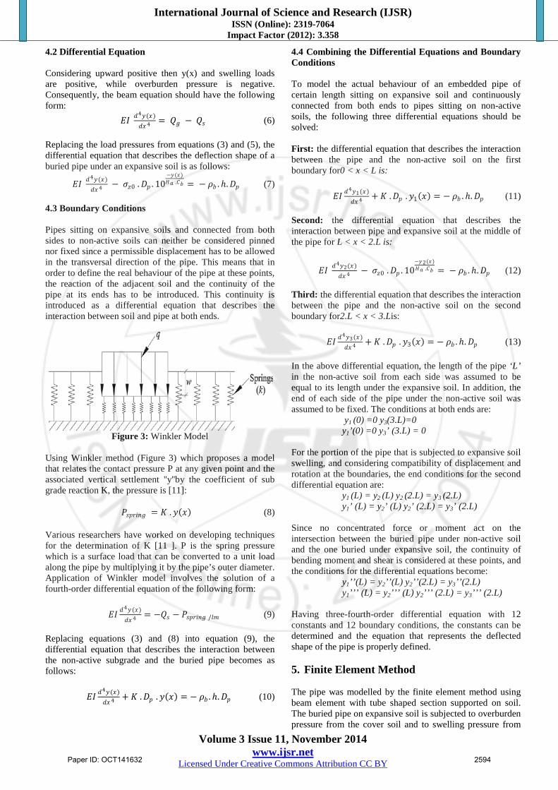
Figure 3: Winkler Model
Using Winkler method (Figure 3) which proposes a model that relates the contact pressure P at any given point and the associated vertical settlement ''y''by the coefficient of sub grade reaction K, the pressure is [11]:
𝑃𝑃𝑠𝑠𝑝𝑝𝑠𝑠𝑠𝑠𝑙𝑙𝑔𝑔 = 𝐾𝐾 . 𝑦𝑦(𝑥𝑥) (8) Various researchers have worked on developing techniques for the determination of K [11 ]. P is the spring pressure which is a surface load that can be converted to a unit load along the pipe by multiplying it by the pipe’s outer diameter. Application of Winkler model involves the solution of a fourth-order differential equation of the following form:
Replacing equations (3) and (8) into equation (9), the differential equation that describes the interaction between the non-active subgrade and the buried pipe becomes as follows:
4.4 Combining the Differential Equations and Boundary Conditions To model the actual behaviour of an embedded pipe of certain length sitting on expansive soil and continuously connected from both ends to pipes sitting on non-active soils, the following three differential equations should be solved: First: the differential equation that describes the interaction between the pipe and the non-active soil on the first boundary for0 < x < L is:
In the above differential equation, the length of the pipe ‘L’ in the non-active soil from each side was assumed to be equal to its length under the expansive soil. In addition, the end of each side of the pipe under the non-active soil was assumed to be fixed. The conditions at both ends are:
y1 (0) =0 y3(3.L)=0 y1’(0) =0 y3’ (3.L) = 0
For the portion of the pipe that is subjected to expansive soil swelling, and considering compatibility of displacement and rotation at the boundaries, the end conditions for the second differential equation are:
Since no concentrated force or moment act on the intersection between the buried pipe under non-active soil and the one buried under expansive soil, the continuity of bending moment and shear is considered at these points, and the conditions for the differential equations become:
Having three-fourth-order differential equation with 12 constants and 12 boundary conditions, the constants can be determined and the equation that represents the deflected shape of the pipe is properly defined. 5. Finite Element Method The pipe was modelled by the finite element method using beam element with tube shaped section supported on soil. The buried pipe on expansive soil is subjected to overburden pressure from the cover soil and to swelling pressure from
International Journal of Science and Research (IJSR) ISSN (Online): 2319-7064
Impact Factor (2012): 3.358
Volume 3 Issue 11, November 2014 www.ijsr.net
Licensed Under Creative Commons Attribution CC BY
the expansive soil.On the other hand, the surcharge load due to cover soil is a constant downward pressure and is modeled as a downward constant force equal to the self-weight of the cover soil calculated from eq. (3). The soil-swelling pressure is a variable force depending on the deflection of the pipe, while the deflection itself is a consequence of this variable force acting on the pipe. An iterative procedure could have been applied in order to match the predicted with the assumed deflection under the same load. However, the modelling of the swelling soil is done using a spring element subjected to expansive soil pressure. The spring used in “Autodesk Robot Structural Analysis Professional 2013” will act opposite to the swelling
pressure, with rigidity equal to the reduction of soil swelling pressure per deflection unit. The model that describes the soil swelling pressure turns to be an upward constant load acting on the pipe combined with a series of springs that work in the opposite direction to reduce the total load until it is equal to the reduced swelling pressure after deflection. Using the spring to account for the reduction of swelling pressure, the total expansive force will be:
𝑄𝑄𝑔𝑔 = 𝑄𝑄𝑔𝑔0 − 𝑄𝑄𝑠𝑠𝑝𝑝𝑠𝑠𝑠𝑠𝑙𝑙𝑔𝑔 (14) and the constitutive law of the spring, shown in Figure 4, should be of the following form:
Figure 4: Constitutive law of the spring used in modeling the swelling pressure.
To properly define the swelling pressure, springs are distributed on a finite number of nodes separated by 1 m. 5.3The boundary conditions The springs are introduced as non-linear elements working only in compression to describe the behaviour of the non-active soil under pressure:
The constitutive law of a spring is introduced in the FEM software and is shown in Figure5.
Figure 5: Constitutive law of the spring replacing the non-active subgrade.
These springs are distributed on a finite number of nodes separated by 1 m and localized on the two elements subjected to non-active soil. 6. Comparison of Results Comparing results of the two methods (Beam differential equation & Finite Element Method), iterative numerical procedure was employed using mathematical solver for differential equations ''NDSolve'' on ''Wolfram Mathematic a
8'' program to determine the deflection of a buried Polyethylene pipe. Applying the above differential equation and finite element method for a pipe length of 15m with 5m under reactive soil gives the plot of the displacement function after equilibrium between swelling pressure and pipe deflection is satisfied. Figure 6 shows the displacement of the pipe using the Beam Differential Equation and using the Finite Element Method.
International Journal of Science and Research (IJSR) ISSN (Online): 2319-7064
Impact Factor (2012): 3.358
Volume 3 Issue 11, November 2014 www.ijsr.net
Licensed Under Creative Commons Attribution CC BY
Figure 6: Displacement plot of the pipe deflection function for the suggested Beam Differential Equation and the Finite
Element Method. Having the deflection function, the bending moment (Figure 7), shear (Figure 8) and the total applied loads (Figure 9), acting on the pipe can be calculated.
Figure 7: Bending moment plot of the pipe for the
suggested Beam Differential Equation and the Finite Element Method.
Figure 8: Shear plot of the pipe for the suggested Beam
Differential Equation and the Finite Element Method
Figure 9: Total applied load plot of the pipe for the suggested Beam Differential Equation and the Finite
Element Method. Comparing the results of the differential equation with the results obtained using the finite element method (Figures 6-9),it can be clearly noticed that the shapes and the values are very close. This proves the accuracy and assures the validity of the suggested model that describes the real behaviour of buried pipes under expansive soil. 7. Results and Analysis Once the validity of our model was assured, FEM can be used to evaluate various geometrical pipe dimensions and determine loads and stresses generated at any pipe section subjected to swelling pressure. Example: A polyethylene pipe having a diameter of 1m, wall thickness of 5cm, and a length of 90m (30 m in the middle are subjected to expansive soil), was modeled with overburden pressure of 2T/lm and a supposed maximum swelling pressure of 5T/lm. Modelling the pipe and applying the boundary conditions and loads acting on the pipe as described before give the results presented in Figures 10 and 11. Figure 10 shows the plot of the displacement function; for the 30 m expansive soil, notice that the maximum value is distributed over a wide range and at both intersections with non-active soil the pipe is under significant rotation.
International Journal of Science and Research (IJSR) ISSN (Online): 2319-7064
Impact Factor (2012): 3.358
Volume 3 Issue 11, November 2014 www.ijsr.net
Licensed Under Creative Commons Attribution CC BY
Figure 10: Plot of the displacement of the pipe subjected to expansive soil.
Based on displacement results and as expected, the maximum swelling deformation of the expansive soil under the overburden pressure is achieved at the middle region of the pipe length; this explains why the pipe deflection is at constant level. Moreover, and in this region, the pipe undergoes a significant deflection which becomes constant in the middle region due to the fact that the swelling pressure is compensated by the overburden pressure of the cover soil. Proceeding with the analysis, loads and stresses diagrams are plotted in Figure 11(a) and (b).
(a) Loads acting on the buried pipe
(b) Stresses acting on the buried pipe
Figure 11: Plots of loads and stresses induced in a buried pipe under expansive soil.
The results of these diagrams assure the validity of the analysis. Notice that all stresses and reactions induced in the pipe are concentrated near the boundaries while in the middle region the loads and stresses are very small. In addition and at the boundaries, the bending moment and shear reach their highest values and change from one sign to the opposite sign which describes the behaviour of the pipe pulled by the swelling soil pressure while on the other side it is blocked from rotation by the sub grade reaction. 8. Comparison with Laboratory Results The applicability of these models was tested by comparing results to real measured values at the laboratory in Queensland University of Technology (QUT), Brisbane Australia, on a two meters long polyethylene pipe buried in reactive clay in a box under laboratory conditions [12]. This laboratory experimental result of a polyethylene pipe tested in an instrumented model box filled with reactive clay soil collected from Merri Creek in Victoria, Australia, presents pipe displacements measured using a specially developed device and soil moisture and suction measurements during soil wetting. Swelling soil and pipe properties were obtained from multiple laboratory test procedures, and introduced as parameters to our model. Values used in the experiment and in the model are: Symbol Description Value Unit
E Young modulus of the High density
polyethylene 70000 t/m2 Dp Pipe external diameter 0.11 m Di Pipe internal diameter 0.085 m σz0 Swelling pressure acting on the pipe 9.81 t/m2 Ha Thickness of swelling soil below the pipe 0.43 m ρb Bulk density of soil 1.15 t/m3 h Depth of the pipe below ground surface 0.2 m
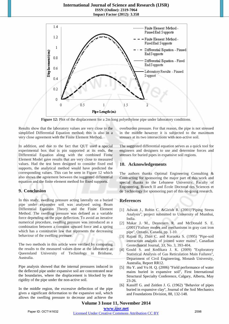
It was observed that the pipe underwent substantial deformation as the soil swelled with the increase of moisture content, and the distribution of measured internal pipe deflection shows significant upward bending of a pipe buried in reactive soil. Since the pipe is installed in an instrumented model box totally filled with reactive clay soil, and the lateral displacement of the pipe is blocked at its ends and the boundary behavior of the pipe in this case acts in a manner close to having a pin supports. Figure 12 shows the laboratory measured displacement of the polyethylene pipe buried in reactive clay compared with the suggested Differential Equation solutions and the combined Finite Element Model for pinned and fixed supports.
International Journal of Science and Research (IJSR) ISSN (Online): 2319-7064
Impact Factor (2012): 3.358
Volume 3 Issue 11, November 2014 www.ijsr.net
Licensed Under Creative Commons Attribution CC BY
Figure 12: Plot of the displacement for a 2m long polyethylene pipe under laboratory conditions.
Results show that the laboratory values are very close to the simplified Differential Equation method; this is also in a very close agreement with the Finite Element Method. In addition, and due to the fact that QUT used a special experimental box that is pin supported at its ends, the Differential Equation along with the combined Finite Element Model gave results that are very close to measured values. Had the test been designed to consider fixed end supports, the analytical method would have predicted the corresponding values. This can be seen in Figure 12 which also shows the agreement between the suggested differential equation and the finite element method for fixed supports. 9. Conclusion In this study, swelling pressure acting laterally on a buried pipe under expansive soil was analysed using Beam Differential Equation Theory and the Finite Element Method. The swelling pressure was defined as a variable force depending on the pipe deflection. To avoid an iterative numerical procedure, swelling pressure was introduced as a combination between a constant upward force and a spring which has a constitutive law that represents the decreasing behaviour of the swelling pressure. The two methods in this article were verified by comparing the results to the measured values done at the laboratory at Queensland University of Technology in Brisbane, Australia. Pipe analysis showed that the internal pressures induced in the deflected pipe under expansive soil are concentrated near the boundaries, where the displacement is blocked by the rigidity of the pipe under the non-active soil. In the middle region, the excessive deflection of the pipe gives a significant deformation to the expansive soil, which allows the swelling pressure to decrease and achieve the
overburden pressure. For that reason, the pipe is not stressed in the middle however it is subjected to the maximum stresses at its two intersections with non-active soil. The suggested differential equation serves as a quick tool for engineers and designers to use and determine forces and stresses for buried pipes in expansive soil regions. 10. Acknowledgements The authors thanks Optimal Engineering Consulting & Contracting for sponsoring the major part of this work and special thanks to the Lebanese University, Faculty of Engineering, Branch II and École Doctoral des Sciences et de Technology for sponsoring part of this on-going research. References
[1] Adwait J., Robin C. &Girish R. (2001)''Piping Stress
Analysis'', project submitted to University of Mumbai, India.
[2] Makar J. M., Desnoyers R. and McDonald S. E. (2001)''Failure modes and mechanisms in gray cast iron pipe'', Ontario, Canada, pp. 1-10.
[3] Rajani B., Zhan C. and Kuraoka S. (1995) ''Pipe-soil interaction analysis of jointed water mains'', Canadian Geotechnical Journal, 33, No. 3, 393-404.
[4] Gould S. and Kodikara J. K. (2009) ''Exploratory Statistical Analysis of Gas Reticulation Main Failures'', Department of Civil Engineering, Monash University, Australia, Report RR12.
[5] Hu Y. and Vu H. Q. (2006) ''Field performance of water mains buried in expansive soil'', First International Structural Specialty Conference, Calgary, Alberta, May 23-26.
[6] Kassiff G. and Zeitlen J. G. (1962) ''Behavior of pipes buried in expansive clay'', Journal of the Soil Mechanics and Foundations Division, 88, 132-148.
International Journal of Science and Research (IJSR) ISSN (Online): 2319-7064
Impact Factor (2012): 3.358
Volume 3 Issue 11, November 2014 www.ijsr.net
Licensed Under Creative Commons Attribution CC BY
[7] WSAA (2008) ''Australian Urban Water Industry'', Water Services Association of Australia, Report card 2007/2008.
[8] Snethen R. (1975) ''A review of engineering experience with expansive soil in highway subgrads'', U.S. army engineering waterways experiment station.
[9] P.-A. von Wolffersdorff & S. Fritzsche (2003) ''Laboratory swell tests on over consolidated clay and diagenetic solidified clay rocks'' Proc. Int. Symp. Geo Technical Measurements and Modelling (GTMM) in Karlsruhe. Ed. O. Natau, E. Fecker, E. Pimentel. A.A. Balkemaa Publishers. pp. 407 – 412
[10] Grob, H. (1972) ''Schwelldrucim Belchentunnel'', In Proceedings of the International Symposium on Underground Openings, Lucerne, Switzerland, pp. 99– 119.
[11] Vesic A. S. (1973) "Slabs on elastic subgrade and Winkler's hypothesis", Eighth International Conference on Soil Mechanics and Foundation Engineering, Moscow, Russia.
[12] Gallage, ChamindaPathma Kumara, Kodikara, Jayantha, & Chan, Derek (2011) Response of a plastic pipe buried in expansive clay. Proceedings of the ICE – Geotechnical Engineering 165(1), pp. 45-57.
[13] Søren H. and Yong B. (1999) ''Bending Moment Capacity of Pipes'', American Bureau of Shipping Offshore Technology Department Houston, Texas USA.
Author Profile Eng. Yves E. AbouRjeily, received his engineering diploma from The Lebanese University, Faculty of Engineering, Branch II, received his Masters from The Lebanese University, École Doctoral des Sciences et de Technologie, and Université de Lille1-Sciences et Technologie. Prof. Michel F. Khouri received his Ph.D. from The University of Michigan, Ann Arbor, in 1989. Since 1993, he is a professor of Civil Engineering at the Lebanese University, Faculty of Engineering, Branch II. Since 2011, he is serving as the Chairman of the Civil Engineering Department; he is also served in the same position from 1997 till 2002 and from 2004 till 2008. He has written many articles in the area of Finite Element Analysis, Structural Dynamics and Shell Analysis.