LONGONI ENGINEERING SRL OPERATING AND MAINTENANCE Ed. 09/2010 Rev. 1 INSTALLATION, OPERATION AND MAINTENANCE OF A SHELL AND TUBE HEAT EXCHANGERS 1‐12 INDEX 1.1 Classification of heat exchangers and components 1.2 Purpose and scope of manual 1.3 General instructions 1.4 Notes for Installation 1.5 Notes for operation 1.6 Note for maintenance 2.1 Purpose and scope 2.2 General Precautions 2.3 Operating procedures for starting and stopping 3.1 Operational procedures for disassembly and cleaning 3.2 Models 3.3 Patterns of disassembly and cleaning 3.4 Warning to disassembly of tube bundles 3.5 Instructions for cleaning the tube bundles In the following pages you will find all the information necessary for the proper use and proper maintenance of your heat exchanger
Transcript
LONGONI ENGINEERING SRL
OPERATING AND MAINTENANCE Ed. 09/2010 Rev. 1
INSTALLATION, OPERATION AND MAINTENANCE OF A SHELL AND TUBE HEAT EXCHANGERS
1‐12
INDEX
1.1 Classification of heat exchangers and components
1.2 Purpose and scope of manual
1.3 General instructions
1.4 Notes for Installation
1.5 Notes for operation
1.6 Note for maintenance
2.1 Purpose and scope
2.2 General Precautions
2.3 Operating procedures for starting and stopping
3.1 Operational procedures for disassembly and cleaning
3.2 Models
3.3 Patterns of disassembly and cleaning
3.4 Warning to disassembly of tube bundles
3.5 Instructions for cleaning the tube bundles
In the following pages you will find all the information necessary for the proper use and proper maintenance of your heat exchanger
LONGONI ENGINEERING SRL
OPERATING AND MAINTENANCE Ed. 09/2010 Rev. 1
INSTALLATION, OPERATION AND MAINTENANCE OF A SHELL AND TUBE HEAT EXCHANGERS
2‐12
1.1 CLASSIFICATION OF HEAT EXCHANGERS AND COMPONENTS
The following figure shows the traditional nomenclature used to identify the main types of heat exchangers and their components.
LONGONI ENGINEERING SRL
OPERATING AND MAINTENANCE Ed. 09/2010 Rev. 1
INSTALLATION, OPERATION AND MAINTENANCE OF A SHELL AND TUBE HEAT EXCHANGERS
3‐12
1.1.2 Type heat exchangers and components
1 Head ‐ flat cover 21 External floating cover
2 Head ‐ bent cover 22 Floating tubesheet
3 Bonnet flange 23 Flange gasket press
4 Flat cober 24 Gasket
5 Flange on head 25 Ring gasket press
6 Fixed tube sheet 26 Ring
7 Tubes 27 Tie rods and spacers
8 Shell 28 Support buffle
9 Shell cover 29 Plate break flow
10 Flange of shell 30 Longitudinal buffle
11 Flange of shell side head 31 Divisor
12 Flange on shell 32 Vent
13 Flange of the shell cover 33 Drain
14 Expansion Joint 34 Attack tools
15 Floating tubesheet 35 Saddles Support
16 Floating Covers 36 Lifting plugs
17 Flange of floating covers 37 Support brackets
18 Ring floating lids 38 Weir
19 Ring into two halves 39 Level attack
20 Against sliding flange
LONGONI ENGINEERING SRL
OPERATING AND MAINTENANCE Ed. 09/2010 Rev. 1
INSTALLATION, OPERATION AND MAINTENANCE OF A SHELL AND TUBE HEAT EXCHANGERS
4‐12
LONGONI ENGINEERING SRL
OPERATING AND MAINTENANCE Ed. 09/2010 Rev. 1
INSTALLATION, OPERATION AND MAINTENANCE OF A SHELL AND TUBE HEAT EXCHANGERS
5‐12
LONGONI ENGINEERING SRL
OPERATING AND MAINTENANCE Ed. 09/2010 Rev. 1
INSTALLATION, OPERATION AND MAINTENANCE OF A SHELL AND TUBE HEAT EXCHANGERS
6‐12
1.2 PURPOSE AND SCOPE OF MANUAL
This manual is designed as a support and guidance for staff use and maintenance of shell and tube heat exchangers
This manual should be read carefully before beginning installation of any heat exchanger tube bundle of Longoni engineering srl in order to ensure proper implementation and better operation.
Note: In this manual are given general guidelines. Customer care will be the responsibility of implementing the instructions, taking into account: ‐ plant where the equipment will be installedTrascrizione fonetica ‐ the specific process ‐ specific maintenance procedures
1.3 GENERAL INSTRUCTION
The performance efficiency of operation of heat transfer equipment, operating life and the absence of problems during the operation, depend in general on the following factors: ‐ Adequate thermal design and mechanical ‐ Adequate arrangements for installation, including plans for the supports and the piping connection ‐ Method of operation ‐ Accuracy of cleaning and maintenance ‐ Adequacy of material, labor and tooling used for maintenance and repairs. Performance problems can be attributed to one or more of the following factors
‐ Exchanger fouling ‐ Operating conditions different from those of project ‐ stagnation of air, gases or liquids ‐ Wrong connection of pipes ‐ Corrosion of internal components ‐ Application of incorrect or faulty storage before installation.
1.4 WARNING INSTALLATION
Upon receipt of the exchanger, check the integrity of same in order to verify that no damage occurred during transit, waiting for the installation to store the heat exchanger in an appropriate manner, preferably in a covered and heated area. If the heat exchanger remains stored for a period exceeding 30 days, you should take precautions to avoid oxidation, dirt and contamination by foreign bodies both internally and externally. After a long period of storage in the warehouse, an inspection is needed before installation of the heat exchanger in order to verify its integrity, you may need to replace the seals.
LONGONI ENGINEERING SRL
OPERATING AND MAINTENANCE Ed. 09/2010 Rev. 1
INSTALLATION, OPERATION AND MAINTENANCE OF A SHELL AND TUBE HEAT EXCHANGERS
7‐12
During the installation, set up in the heat exchanger in order to allow the connection of pipes without force. Before connecting the pipes, remove the protection of openings, carefully check all access openings to remove any debris. Do not expose to the atmosphere the interior passages of the heat exchanger, as humidity and pollutants can penetrate into the heat exchanger and possible damage and / or failures.
For heat exchangers, shell and tube removable, leaving sufficient space to allow the extraction of the beam. For heat exchangers, shell and tube drive, leave enough space for maintenance and cleaning on one side and leave enough space for the 'replacement of the pipes. In order to allow the isolation of the heat exchanger in order to permit cleaning and maintenance, install the valves and by‐pass on the pipes. In order to prevent and / or remove any trapped air or gas, both to cloak the side pipes, you should install air release valves. Achieving adequate support for mounting the heat exchanger to prevent sagging and deformations that may affect the mechanical efficiency of the heat exchanger. Fix the heat exchanger so that it has freedom of movement due to the lengthening of expansion. Install the appropriate control devices, control and related devices and / or safety alerts over or under temperature, pressure, etc.. In the heat exchangers and steam condensation usually occur the perfect drainage of condensate. Connect the equipment to the ground.
1.5 NOTE FOR OPERATION
Before the operation to ensure the cleanliness of the interior of the system to avoid clogging the pipes or the shell side. We recommend the use of settling tanks or filters installed on the supply pipes to remove debris. Open the vents before starting, begin gradually put into operation in accordance with the procedures of starting and stopping that will be specified later. Once the system completely filled with process fluids close the vents. All the bolts with the seal of the joints, should be further tightened once the heat exchanger has reached operating temperature to avoid any losses from the seals. Do not operate the heat exchanger at temperatures and pressures other than those listed on the nameplate or on the declaration of conformity. Do not use fluids other than those indicated, since the use of fluids other than those for which the equipment was designed and built could trigger corrosion or erosion that could affect the mechanical efficiency of the device. In heat exchangers that work in the condensation of hot fluids, to prevent water hammer, is starting down that the condensation must be drained completely by the heat exchangers. Avoid fluctuations in fluids in the exchangers, since these fluctuations could cause vibrations that could compromise the functionality of the device and the mechanical strength. At the time of the stop, drain all fluids, to avoid stagnation of fluids that may freeze in the cold or trigger corrosion. Use common sense and make any reference to procedures for commissioning of the plant where the device is inserted
LONGONI ENGINEERING SRL
OPERATING AND MAINTENANCE Ed. 09/2010 Rev. 1
INSTALLATION, OPERATION AND MAINTENANCE OF A SHELL AND TUBE HEAT EXCHANGERS
8‐12
1.6 MAINTENANCE NOTES
To keep in perfect condition and ensure the best operating conditions of a heat exchanger is a good idea to carry out maintenance and cleaning. Trip times vary depending on the type of fluid, impurities or deposits present, the operating temperature, the user will have to adjust according to our experience and based on a few easily identifiable parameters, the yield of heat exchanger, which decreases or the pressure drop of the fluid increases are symptoms that indicate that the heat exchanger needs cleaning. Increasing the thickness of the deposits also increases the difficulty of cleaning. Failure to clean the pipes, and the resulting scale deposits can cause a different heat output of the tubes, also adjacent, and this can lead to different thermal expansion between tubes with a possible subsequent collapse. Never remove the covers of the mantle or floating heads without first stopping the plant, removing all pressure equipment and empty without him. For all maintenance and cleaning, use appropriate personal protective equipment based on the fluid contained in the heat exchanger and, if necessary ventilation. To clean or inspect the inside of the tubes removed lids only necessary on the tube side, for cleaning the outside of the tubes is necessary to extract the tube. Caution, not all heat exchangers are removable in this case usually proceeds with a chemical cleaning (using a product that does not affect the materials) circulating in the mantle a product that washes the surface. E 'by the customer decide which type of heat exchanger is best suited to their needs to use. To detect cracks and corrosion in the pipes or leaks in the connections between pipes and tube plate, you should take the following steps: ‐ Remove the caps from the tube side,
‐ Pressurize the mantle, not to exceed the maximum test pressure, using a cold liquid (preferably water), ‐ Observe expanding or welding of the tubes and the adjacent areas, the inner tubes and tube plate
For certain types of heat exchangers is necessary to use the rings and gaskets test. To revert to the tightness of a pipe is leaking at the fitting on the tube plate, if the seal is effected by expansion of the tube by rolling expansion, restore the sealing mandrel tube, sometimes after a leaky pipe mandrel is needed chuck (not excessively), also the adjacent tubes, if the seal is welded between tube and plate, you must restore the weld (use the same type of pipe material and the plate). All these operations must be carried out by competent personnel and suitable equipment. In case of removal of the heat exchanger at the time of replacement, consider replacing old gaskets with new gaskets, seals during assembly and are crushed and deformed during use tend to become brittle. E 'recommended the use of bolts and nuts to match the new specifications of existing ones. 2 PROCEDURE FOR STARTING AND STOPPING OF SHELL AND TUBE HEAT EXCHANGER
2.1 PURPOSE AND SCOPE
LONGONI ENGINEERING SRL
OPERATING AND MAINTENANCE Ed. 09/2010 Rev. 1
INSTALLATION, OPERATION AND MAINTENANCE OF A SHELL AND TUBE HEAT EXCHANGERS
9‐12
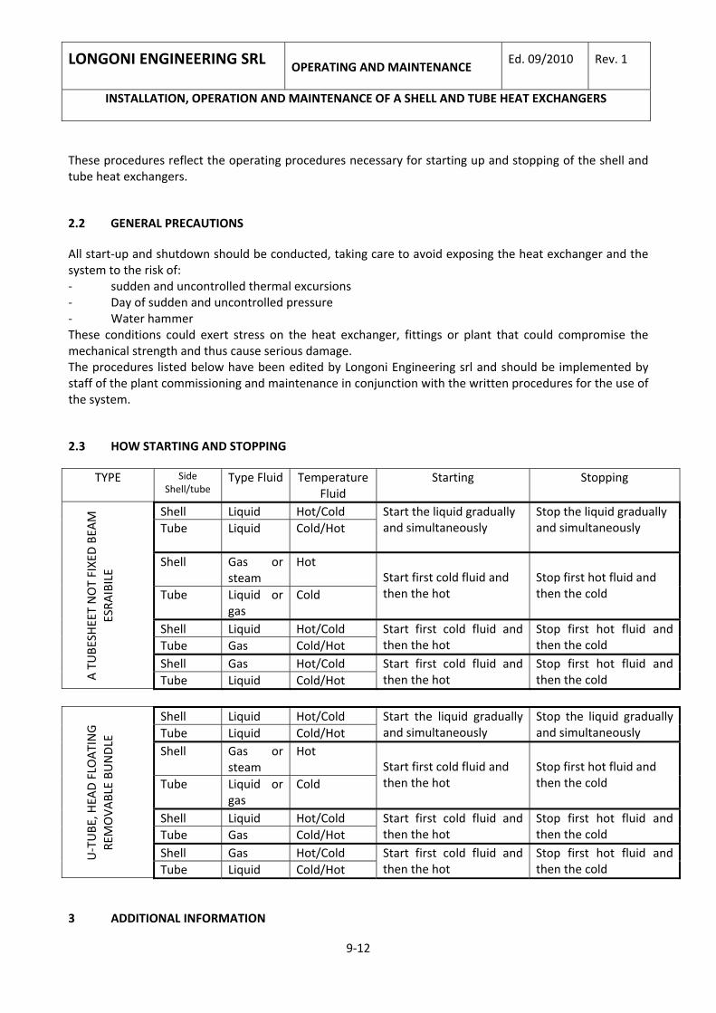
These procedures reflect the operating procedures necessary for starting up and stopping of the shell and tube heat exchangers.
2.2 GENERAL PRECAUTIONS
All start‐up and shutdown should be conducted, taking care to avoid exposing the heat exchanger and the system to the risk of: ‐ sudden and uncontrolled thermal excursions ‐ Day of sudden and uncontrolled pressure ‐ Water hammer These conditions could exert stress on the heat exchanger, fittings or plant that could compromise the mechanical strength and thus cause serious damage. The procedures listed below have been edited by Longoni Engineering srl and should be implemented by staff of the plant commissioning and maintenance in conjunction with the written procedures for the use of the system.
2.3 HOW STARTING AND STOPPING
TYPE Side Shell/tube
Type Fluid Temperature Fluid
Starting Stopping
Shell Liquid Hot/Cold Tube Liquid Cold/Hot
Start the liquid gradually and simultaneously
Stop the liquid gradually and simultaneously
Shell Gas or steam
Hot
Tube Liquid or gas
Cold Start first cold fluid and then the hot
Stop first hot fluid and then the cold
Shell Liquid Hot/Cold Tube Gas Cold/Hot
Start first cold fluid and then the hot
Stop first hot fluid and then the cold
Shell Gas Hot/Cold
A TUBE
SHEET NOT FIXED BEA
M
ESRA
IBILE
Tube Liquid Cold/Hot Start first cold fluid and then the hot
Stop first hot fluid and then the cold
Shell Liquid Hot/Cold Tube Liquid Cold/Hot
Start the liquid gradually and simultaneously
Stop the liquid gradually and simultaneously
Shell Gas or steam
Hot
Tube Liquid or gas
Cold Start first cold fluid and then the hot
Stop first hot fluid and then the cold
Shell Liquid Hot/Cold Tube Gas Cold/Hot
Start first cold fluid and then the hot
Stop first hot fluid and then the cold
Shell Gas Hot/Cold U‐TUBE
, HEA
D FLO
ATING
REMOVA
BLE BU
NDLE
Tube Liquid Cold/Hot Start first cold fluid and then the hot
Stop first hot fluid and then the cold
3 ADDITIONAL INFORMATION
LONGONI ENGINEERING SRL
OPERATING AND MAINTENANCE Ed. 09/2010 Rev. 1
INSTALLATION, OPERATION AND MAINTENANCE OF A SHELL AND TUBE HEAT EXCHANGERS
10‐12
In all operations starting and stopping the flow of fluids should be adjusted so as to avoid sudden changes in temperature of the heat exchanger regardless of whether the tube is removable or not. You should not use ON‐OFF valves but modular valves. You can start before the hot fluid and then the cold but avoiding the cold fluid in contact with hot surfaces tends to evaporate.
3.1 METHODS 'FOR THE REMOVAL AND CLEANING OPERATIVE
Dismantling and cleaning of heat exchangers is a simple task to be performed by qualified personnel using appropriate personal protective equipment and apply appropriate protection systems also based on the fluid in the heat exchanger. Dismantling and cleaning can vary depending on the type of equipment, will be summarized to the following types of heat exchangers and the disassembly and cleaning procedures associated with them.
3.2 MODELS
A U‐Tube Bundle
B Fixed Tubesheet
C Packed Floating Tubesheet
With Lantern ring
LONGONI ENGINEERING SRL
OPERATING AND MAINTENANCE Ed. 09/2010 Rev. 1
INSTALLATION, OPERATION AND MAINTENANCE OF A SHELL AND TUBE HEAT EXCHANGERS
11‐12
D Floating Head
E Type Reboiler
F Type Reboiler
3.3 SCHEDULE OF DISASSEMBLY AND CLEANING
Type Disassembly Cleaning
A ‐unscrew the bolts ‐Remove the head ‐Extract the bundle
‐Clean the inside of the tubes chemically ‐Clean the outside of mechanically or with cleaning solution to soak
B ‐unscrew the bolts ‐Remove both the heads
‐Clean the inside of the tubes through scovolatura ‐Clean the outside of the tubes by circulating a cleaning solution in the mantle
C ‐unscrew the bolts ‐Remove the head ‐ Remove the seals and sealing ring
‐Clean the inside and outside of mechanically or with cleaning solution to soak
D ‐unscrew the bolts ‐ Remove the cap and the floating ring ‐Extract the bundle
‐Clean the outside of mechanically or with cleaning solution to soak
E ‐unscrew the bolts ‐Remove the head ‐Extract the bundle
‐Clean the inside of the tubes chemically‐Clean the outside of mechanically or with cleaning solution to soak
OPERATING AND MAINTENANCE
Ed. 09/2010 Rev. 1 LONGONI ENGINEERING SRL
INSTALLATION, OPERATION AND MAINTENANCE OF A SHELL AND TUBE HEAT EXCHANGERS
12‐12
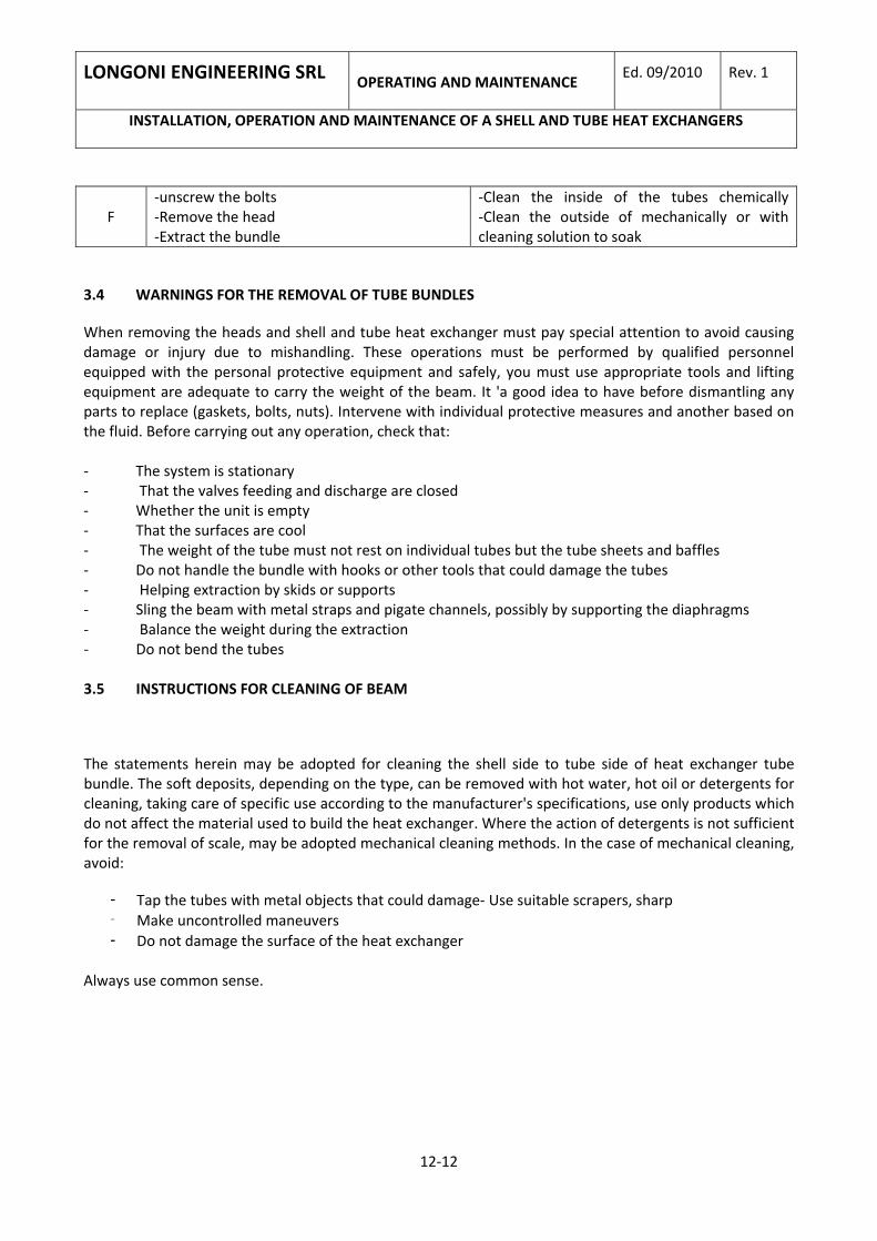
F ‐unscrew the bolts ‐Remove the head ‐Extract the bundle
‐Clean the inside of the tubes chemically‐Clean the outside of mechanically or with cleaning solution to soak
3.4 WARNINGS FOR THE REMOVAL OF TUBE BUNDLES
When removing the heads and shell and tube heat exchanger must pay special attention to avoid causing damage or injury due to mishandling. These operations must be performed by qualified personnel equipped with the personal protective equipment and safely, you must use appropriate tools and lifting equipment are adequate to carry the weight of the beam. It 'a good idea to have before dismantling any parts to replace (gaskets, bolts, nuts). Intervene with individual protective measures and another based on the fluid. Before carrying out any operation, check that: ‐ The system is stationary ‐ That the valves feeding and discharge are closed ‐ Whether the unit is empty ‐ That the surfaces are cool ‐ The weight of the tube must not rest on individual tubes but the tube sheets and baffles ‐ Do not handle the bundle with hooks or other tools that could damage the tubes ‐ Helping extraction by skids or supports ‐ Sling the beam with metal straps and pigate channels, possibly by supporting the diaphragms ‐ Balance the weight during the extraction ‐ Do not bend the tubes 3.5 INSTRUCTIONS FOR CLEANING OF BEAM
The statements herein may be adopted for cleaning the shell side to tube side of heat exchanger tube bundle. The soft deposits, depending on the type, can be removed with hot water, hot oil or detergents for cleaning, taking care of specific use according to the manufacturer's specifications, use only products which do not affect the material used to build the heat exchanger. Where the action of detergents is not sufficient for the removal of scale, may be adopted mechanical cleaning methods. In the case of mechanical cleaning, avoid:
- Tap the tubes with metal objects that could damage‐ Use suitable scrapers, sharp - Make uncontrolled maneuvers - Do not damage the surface of the heat exchanger