Loop Antenna Boosts AM Radio Reception of Weak Signals No batteries or electrical connection required! The tuned-loop antenna works to improve reception in the AM broadcast band of most any radio it is placed against. With the exception of the wire, it is built entirely from items that are commonly found in a household or may be procured at little or no expense. Similarly, its construction requires no special skills or tools. In fact, youngsters above the age of eight may find this project to be an outlet for their creativity. Note that this project must be spread over two days in order to let glue dry. How it works When tuned to the frequency of a radio signal being broadcast, the loop antenna reacts to the oscillating magnetic field of the radio wave, resulting in a weak electrical current flowing through the multiple turns of wire. This small electrical current, which might be viewed as having being “concentrated” by the coil, may then be inductively coupled into the built-in AM “loopstick” antenna of a radio placed next to it. This occurs because the radio's antenna also contains many turns of wire, and the two windings are able to react with one another, even though separated by a significant gap. The net result is that the radio signal gathered by the loop antenna serves to add to that received by the radio's (generally smaller) internal antenna, resulting in stronger reception. To achieve maximum results, the loop obviously must be placed in the position that achieves the best coupling, which will vary between radios and therefore is a matter of experimentation. The degree of improvement in reception that can be accomplished also depends on the radio, with more compact models generally displaying the largest improvement due to the small size of their built-in antenna. The loop only works with signals in the AM broadcast band, and more specifically, with frequencies that are on the upper portion of the radio dial. This latter restriction is simply due to the limits of the homemade tuning capacitor, which does not have the capacity needed to tune across the entire band. This adjustable capacitor, which is connected between the ends of the coil of wire, is what completes the electrical circuit for the radio waves and allows resonance to be achieved at the selected frequency. It is the resonance with the radio wave which this “tuned circuit” creates that boosts the amount of current flowing through the wire and thereby the signal received on the adjacent radio. Materials needed Empty breakfast cereal box, 7.5” x 11.25” or larger Small piece of paper Water-soluble “white” or “school” glue Cellophane tape Aluminum foil (2” length or longer and width of the roll) 2 plastic drinking straws (straight style preferred) Crayon, wax candle or small piece of waxed paper 75 feet or more of small-gauge, insulated wire (see instructions) Tools needed 12” ruler (or tape measure, plus a straightedge) Pencil (preferably with an eraser) Scissors Old toothbrush Stapler (ordinary type for paper) Small wire cutters (optional)
Transcript
Loop Antenna Boosts AM Radio Reception of Weak SignalsNo batteries or electrical connection required!
The tuned-loop antenna works to improve reception in the AM broadcast band of most any radio it is placed against. With the exception of the wire, it is built entirely from items that are commonly found in a household or may be procured at little or no expense. Similarly, its construction requires no special skills or tools. In fact, youngsters above the age of eight may find this project to be an outlet for their creativity. Note that this project must be spread over two days in order to let glue dry.
How it worksWhen tuned to the frequency of a radio signal being broadcast, the loop antenna reacts to the oscillatingmagnetic field of the radio wave, resulting in a weak electrical current flowing through the multiple turns of wire. This small electrical current, which might be viewed as having being “concentrated” by the coil, may then be inductively coupled into the built-in AM “loopstick” antenna of a radio placed next to it. This occurs because the radio's antenna also contains many turns of wire, and the two windings are able to react with one another, even though separated by a significant gap. The net result is that the radio signal gathered by the loop antenna serves to add to that received by the radio's (generally smaller) internal antenna, resulting in stronger reception. To achieve maximum results, the loop obviously must be placed in the position that achieves the best coupling, which will vary between radios and therefore is a matter of experimentation. The degree of improvement in reception that can beaccomplished also depends on the radio, with more compact models generally displaying the largest improvement due to the small size of their built-in antenna. The loop only works with signals in the AM broadcast band, and more specifically, with frequencies that are on the upper portion of the radio dial. This latter restriction is simply due to the limits of the homemade tuning capacitor, which does nothave the capacity needed to tune across the entire band. This adjustable capacitor, which is connected between the ends of the coil of wire, is what completes the electrical circuit for the radio waves and allows resonance to be achieved at the selected frequency. It is the resonance with the radio wave which this “tuned circuit” creates that boosts the amount of current flowing through the wire and thereby the signal received on the adjacent radio.
Materials neededEmpty breakfast cereal box, 7.5” x 11.25” or largerSmall piece of paperWater-soluble “white” or “school” glueCellophane tapeAluminum foil (2” length or longer and width of the roll)2 plastic drinking straws (straight style preferred)Crayon, wax candle or small piece of waxed paper75 feet or more of small-gauge, insulated wire (see instructions)
Tools needed12” ruler (or tape measure, plus a straightedge)Pencil (preferably with an eraser)ScissorsOld toothbrushStapler (ordinary type for paper)Small wire cutters (optional)
Other itemsFlat work surface that is washableWaxed paper or plastic wrapOld toothbrushBooks (to provide weight)Picture or photograph (for optional customization)
PreparationDue to the thin nature of the cardboard and the desirability of having an exposed surface that is blank, rather than printed, you will be gluing two pieces cut from the box together. As this process can be messy, it is recommended it be done on a washable, flat surface such as a kitchen table or countertop. In addition, the glued pieces must be held down flat while the glue dries. Therefore, you will want to have some large, hardcover books or something similar readily available that can be used to provide weight. These may be protected from damage by placing a sheet of waxed paper or plastic wrap between them and the cardboard. If you are using poster-board in place of a cereal box, the steps outlined in the initial construction may be skipped.
The loop antenna you create can be decorated to resemble a picture frame if you wish, and can optionally have a cardboard support to keep it upright (see figures 8 & 9). If you wish to go this route, follow the instructions for saving and gluing together the side panels cut from the cereal box.
Initial Construction (day 1)1. Carefully cut open the empty cereal box so you have two rectangular pieces of cardboard (the
front and back of the box) that measure approximately 7-1/2 inches by 11-1/4 inches. Larger is okay, as the excess may be trimmed off later. You should save either the top or bottom of the box as well as the two side pieces, if you'll be building the optional stand (see figure 1).
2. With the printed portion of both the front and back of the box (and that of the two side panels, ifsaved) on a flat surface facing up, apply the water-based glue over each surface and spread it around evenly with a finger or an old toothbrush. Be sure to spread glue all the way to the very edges of the cardboard.
3. Carefully place the front of the box, printed portion facing down, on top of the matching back piece. Also do this with the side panels (if you will be creating a stand). Try to get the edges of each piece aligned as best you can, then run your hand over the entire top while applying pressure in order to squeeze the two pieces of cardboard tightly together.
4. Use a paper towel or napkin to wipe off any excess glue that may have oozed out and move the assembled pieces to a flat surface where they will not be in the way while the glue dries for a day. It's best to keep the pieces flat and pressed together by stacking some books on top, which can be protected from damage by first placing a piece of waxed paper or plastic wrap over the cardboard surfaces.
5. Use a damp sponge, wash cloth or paper towel to clean up any glue left on the work surface, as needed.
Preparing the cardboard form (day 2)1. After allowing at least 20 hours of drying time, the two pieces of cardboard may be retrieved
and work on the project resumed. If made, the assembly from the two side panels of the cereal box can be set aside for the time being. Use figure 2 as a reference for the following steps.
2. Cut the assembly consisting of the front and back pieces of the box (or poster-board) to 7-1/2” by 11-1/4” as needed.
3. Using a ruler or tape measure in conjunction with a straightedge, mark with a pencil an inch in from the beginning and end of each of the four edges of the cardboard (8 marks total).
4. Draw a pencil line between the points along each edge to form a rectangle. Also draw a line between the very tip of each of the four corners of the cardboard and those of the rectangle just drawn.
5. With the ruler or tape measure placed against a long edge of the cardboard, make pencil marks at the following points: 2-1/8”, 2-1/4”, 3-1/4”, 3-3/8”, 4-3/8”, 4-1/2”, 5-1/2”, 5-5/8”, 6-5/8”, 6-3/4”, 7-3/4”, 7-7/8”, 8-7/8”, 9”.
6. Repeat the previous step with the ruler or tape measure placed against the opposite edge of the cardboard (the other long edge).
7. With the ruler or tape measure placed against a short edge of the cardboard, make pencil marks at the following points: 2”, 2-1/8”, 3-1/8”, 3-1/4”, 4-1/4”, 4-3/8”, 5-3/8”, 5-1/2”.
8. Repeat the previous step with the ruler or tape measure placed against the opposite edge of the cardboard (the other short edge).
9. Using a ruler or straightedge, connect the marks you made on opposite edges of the cardboard with pencil lines that go between the outer edge of the cardboard and the lines forming the innerrectangle. In other words, you don't need to draw any lines through the inner rectangle. You willinstead be making 44 short lines that are 1” in length (see figure 2).
10. Find the diagonal lines you initially drew at the 4 corners (points) of the cardboard. Using scissors, make a cut 1/16th of an inch to either side of this line, just long enough to reach the edge of the drawn rectangle. This will result in a narrow piece of cardboard an eighth of an inchwide that can then be removed. Wire cutters work well for snipping the far end.
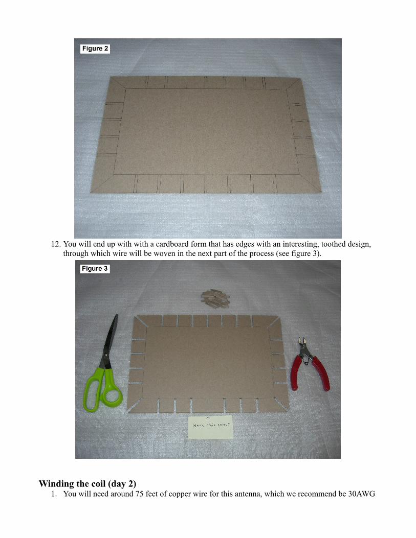
11. Using the short lines drawn in previous steps as a guide, use scissors to cut out all but one of the1/8” wide strips along the perimeter of the cardboard. The exception will be the center-most strip on one of the long edges. Leave this particular “tooth” doubly wide as we will need an oddnumber of them in order to weave the wire properly in a later step. To clarify, you are removing the cardboard from the narrow spaces between lines.
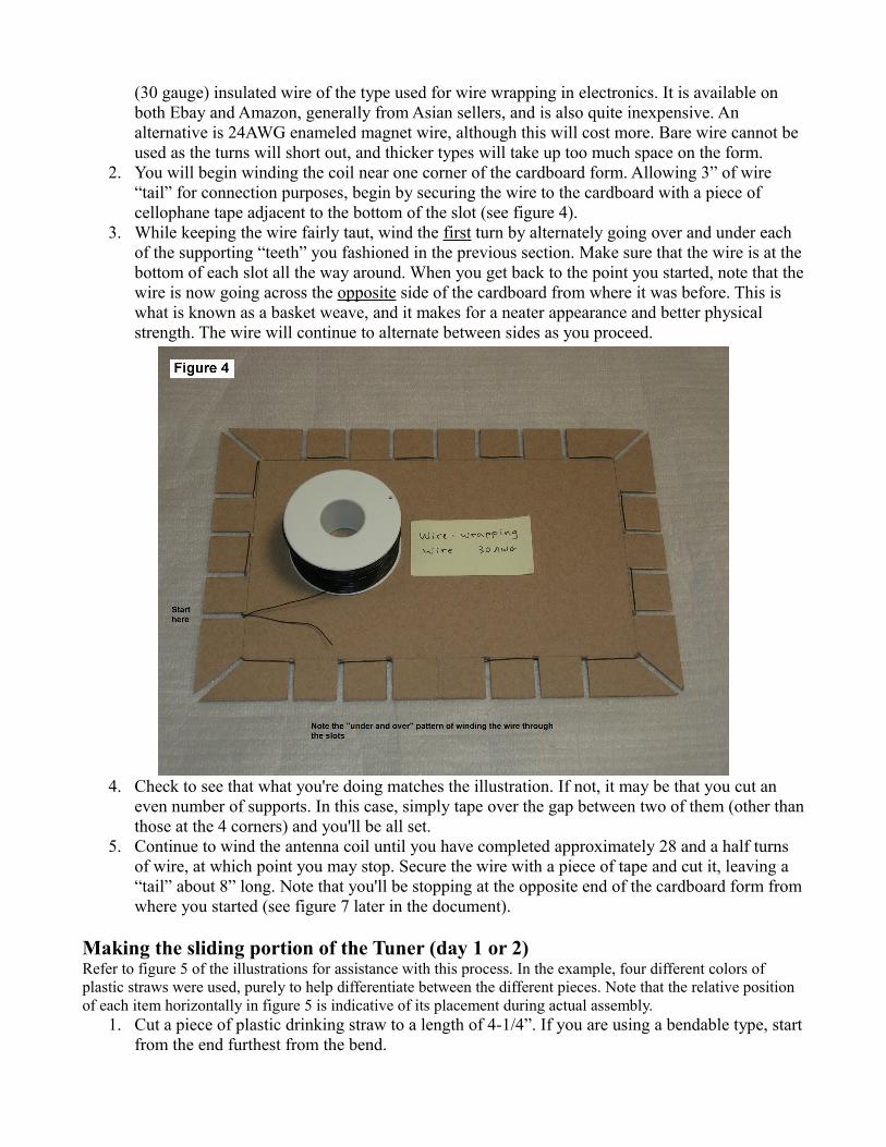
12. You will end up with with a cardboard form that has edges with an interesting, toothed design, through which wire will be woven in the next part of the process (see figure 3).
Winding the coil (day 2)1. You will need around 75 feet of copper wire for this antenna, which we recommend be 30AWG
(30 gauge) insulated wire of the type used for wire wrapping in electronics. It is available on both Ebay and Amazon, generally from Asian sellers, and is also quite inexpensive. An alternative is 24AWG enameled magnet wire, although this will cost more. Bare wire cannot be used as the turns will short out, and thicker types will take up too much space on the form.
2. You will begin winding the coil near one corner of the cardboard form. Allowing 3” of wire “tail” for connection purposes, begin by securing the wire to the cardboard with a piece of cellophane tape adjacent to the bottom of the slot (see figure 4).
3. While keeping the wire fairly taut, wind the first turn by alternately going over and under each of the supporting “teeth” you fashioned in the previous section. Make sure that the wire is at thebottom of each slot all the way around. When you get back to the point you started, note that thewire is now going across the opposite side of the cardboard from where it was before. This is what is known as a basket weave, and it makes for a neater appearance and better physical strength. The wire will continue to alternate between sides as you proceed.
4. Check to see that what you're doing matches the illustration. If not, it may be that you cut an even number of supports. In this case, simply tape over the gap between two of them (other thanthose at the 4 corners) and you'll be all set.
5. Continue to wind the antenna coil until you have completed approximately 28 and a half turns of wire, at which point you may stop. Secure the wire with a piece of tape and cut it, leaving a “tail” about 8” long. Note that you'll be stopping at the opposite end of the cardboard form fromwhere you started (see figure 7 later in the document).
Making the sliding portion of the Tuner (day 1 or 2)Refer to figure 5 of the illustrations for assistance with this process. In the example, four different colors of plastic straws were used, purely to help differentiate between the different pieces. Note that the relative position of each item horizontally in figure 5 is indicative of its placement during actual assembly.
1. Cut a piece of plastic drinking straw to a length of 4-1/4”. If you are using a bendable type, startfrom the end furthest from the bend.
2. Tear off a length of aluminum foil that is at least 2” long and the width of the roll. From this, cuta piece that is 4” wide and 1-1/2” long.
3. With the foil placed on a flat surface, use finger pressure to smooth it out and make it nice and thin.
4. Align one of the short edges of the foil with the right end of the straw and with the long edge of the foil centered down the length of the straw, fasten the two together near the middle with a small piece of cellophane tape.
5. Tightly roll the foil around the straw and secure the loose edge with two small pieces of tape. One should be placed at the end where the straw is still exposed and should overlap both foil and plastic in order to keep the foil from sliding on the straw. The other piece of tape should go about an inch in from the other end of the straw that is covered with foil. It is important that the last ¾ of an inch be kept free from tape or other insulating material, as an electrical connection will be made here later on.
6. Cut a piece from the second straw that is 3-1/2” long. If you are using a bendable type, once again start from the end furthest from the bend.
7. Using scissors, slit lengthwise up this piece of straw so that it can be enlarged. Using a finger tohold one end open, slide this new piece over the foil-covered one you made in the previous step.Align the end of this “cover” with the end of the first piece that has the quarter inch of straw showing beyond the foil.
8. Dispense a piece of tape that is roughly 4” long. Line one end of it up with the end of the “cover” you just made from which the foil-covered straw protrudes and straddling the slit, tape both sections of the split straw and the foil underneath together. Trim off all but 1/4” of the excess tape that hangs off the end of the assembly. Now, using a pencil, tuck the remaining “tail” of tape up inside the straw and press it against the inner wall. This will avoid having an edge of tape that could flip up and cause problems when the straw is slid in and out.
Making the fixed portion of the Tuner (day 1 or 2)1. Take one of the remaining pieces of straw and cut it to a length of 4-1/2”. Using the scissors, slit
this lengthwise so it can be expanded.2. From a sheet of paper, cut a piece 5” long and 1/2” wide. This will be used as a temporary
spacer. If the particular drinking straws you are using happen to be quite small in diameter, reduce the width of this spacer to 3/8”.
3. Use a crayon, wax candle or piece of waxed paper to lightly rub some wax along both sides of the paper spacer, as well as along the sliding portion of the tuner assembly you created earlier. However, do not put any wax on the exposed aluminum foil at the end where the electrical connection will be made. The wax will help things slide more easily.
4. Place the sliding portion made earlier on the work surface in front of you with the paper spacer balanced lengthwise on top of it. You may wish to work the paper into a “U” shape with your fingers to help it stay in place. Next, using a finger to hold one end of the newly-split straw wide open, place it over the slider assembly and paper spacer in order to form a cover, similar towhat was done earlier.
5. Slide the cover so that one end is 7/8” away from the end of the slider that has the exposed foil. Note that the other end of the split straw will extend about an inch beyond the slider and being unsupported, will exhibit a sort of taper. Try to have all of the paper spacer covered by the strawand not sticking out of the slit.
6. Cut a piece of foil 4-1/4” long and 1-1/2” high and smooth it out with your fingers as done previously.
7. Align one of the short edges of the foil with the far (tapered) end of the straw and with the long edge of the foil centered down the length of the straw, fasten the two together near the center with a small piece of cellophane tape, being sure that the tape does not go into the area exposed by the slit, where it would interfere with the movement of the slider.
8. Tightly roll the foil around the straw and secure the loose end with two small pieces of tape. One should be placed near the end closest to the slider and the other piece about an inch in fromthe tapered end of the straw. Again, it is important that the last ¾ of an inch of the foil be kept free from tape or other insulating material, as an electrical connection will be made here later on.
9. Cut the remaining piece of straw to 3-1/2” and slit it lengthwise. If you come up a little short onlength, just use what is available. Using a finger to hold one end of the newly-split straw wide open, place it over the assembly just made in order to form a cover, similar to what had been done twice before. Position the split straw so that one end is an inch in from the (tapered) end ofthe tuner. You may use a piece of tape to fasten the two edges of the split to the foil underneath, but do not extend it beyond the ends of the straw as doing so could interfere with the electrical connection at one end, or free movement of the slider at the other.
10. Remove the temporary paper spacer by pulling it out. You may find it easier to do this if you pull the slider part way out, but be careful not to pull it out fully as it will be difficult to reinsert.Finally, grasp the foil ends of the completed piston tuner assembly and check to see that the twosections slide easily with some resistance.
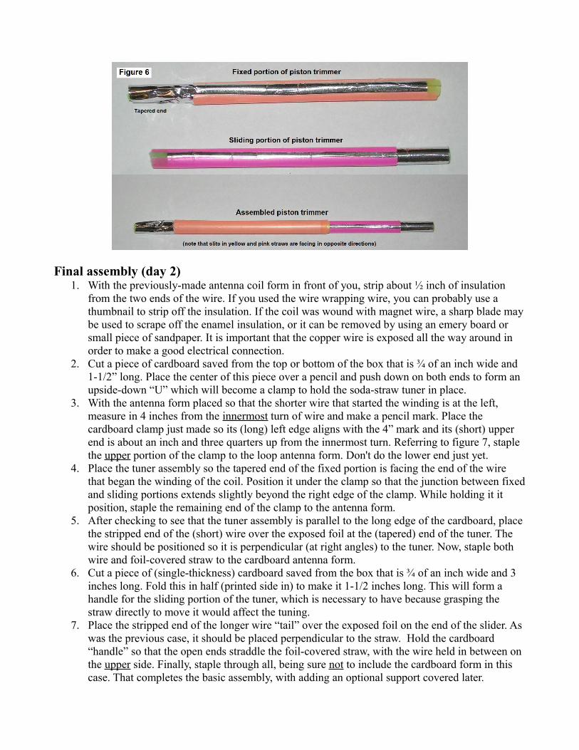
Although you'd generally not want to take the two sections apart, the upper portion of figure 6 shows how each will look when completed. The interaction between the pieces of foil in the two sections is what allows the loop to be tuned to a specific frequency. Electrical capacity increases as the amount of foil from the sliding portion in close proximity to the foil on the fixed portion increases. This lowers the tuned frequency and the opposite will be true as the amount of interaction decreases as the sections are pulled apart.
Final assembly (day 2)1. With the previously-made antenna coil form in front of you, strip about ½ inch of insulation
from the two ends of the wire. If you used the wire wrapping wire, you can probably use a thumbnail to strip off the insulation. If the coil was wound with magnet wire, a sharp blade maybe used to scrape off the enamel insulation, or it can be removed by using an emery board or small piece of sandpaper. It is important that the copper wire is exposed all the way around in order to make a good electrical connection.
2. Cut a piece of cardboard saved from the top or bottom of the box that is ¾ of an inch wide and 1-1/2” long. Place the center of this piece over a pencil and push down on both ends to form an upside-down “U” which will become a clamp to hold the soda-straw tuner in place.
3. With the antenna form placed so that the shorter wire that started the winding is at the left, measure in 4 inches from the innermost turn of wire and make a pencil mark. Place the cardboard clamp just made so its (long) left edge aligns with the 4” mark and its (short) upper end is about an inch and three quarters up from the innermost turn. Referring to figure 7, staple the upper portion of the clamp to the loop antenna form. Don't do the lower end just yet.
4. Place the tuner assembly so the tapered end of the fixed portion is facing the end of the wire that began the winding of the coil. Position it under the clamp so that the junction between fixedand sliding portions extends slightly beyond the right edge of the clamp. While holding it it position, staple the remaining end of the clamp to the antenna form.
5. After checking to see that the tuner assembly is parallel to the long edge of the cardboard, place the stripped end of the (short) wire over the exposed foil at the (tapered) end of the tuner. The wire should be positioned so it is perpendicular (at right angles) to the tuner. Now, staple both wire and foil-covered straw to the cardboard antenna form.
6. Cut a piece of (single-thickness) cardboard saved from the box that is ¾ of an inch wide and 3 inches long. Fold this in half (printed side in) to make it 1-1/2 inches long. This will form a handle for the sliding portion of the tuner, which is necessary to have because grasping the straw directly to move it would affect the tuning.
7. Place the stripped end of the longer wire “tail” over the exposed foil on the end of the slider. As was the previous case, it should be placed perpendicular to the straw. Hold the cardboard “handle” so that the open ends straddle the foil-covered straw, with the wire held in between on the upper side. Finally, staple through all, being sure not to include the cardboard form in this case. That completes the basic assembly, with adding an optional support covered later.
Testing/using the loop antenna1. Tune the AM radio to a weak station between 1250KHz and 1710KHz and rotate it to obtain the
strongest reception.2. Place the loop antenna an inch or so away from the radio and at a 45 degree angle to one end.
Hold it upright in the vertical orientation by a corner so your fingers aren't in close proximity to the wire, which will affect the tuning.
3. With your free hand, grasp the cardboard handle of the piston trimmer and move it in and out until you obtain either a peak or a null in the signal. If the latter, you may need to move the antenna to a different position as it is canceling the signal, rather than boosting it. Keep your fingers away from the wire when tuning to avoid affecting the reception.
4. Once a clear peak has been obtained, experiment with moving the antenna to different positions around the radio and adjust the proximity to it to see if further improvement in the signal strength can be obtained. Every radio is likely to be different in this respect and the most dramatic improvement in reception is likely to be achieved with radios that have a small internal antenna, such as pocket portables.
5. The sliding trimmer will need to be adjusted for a new peak whenever the radio is tuned to a different frequency.
6. An improvement in locally-generated interference can sometimes be had with the loop placed ina particular position. In some circumstances, the signal-to-noise ratio can be improved by simply reversing the side of the loop that is facing the radio.
Optional support attachmentThere's no reason your loop antenna can't have some class. You can turn it into a self-standing pseudo-picture frame by gluing a hinged, cardboard support to the back and attaching a picture or drawing to the front. See the illustrations to get an idea of how it was done on the example wound with enameled magnet wire. The support measures 1-3/4” wide and 7-1/4” long and is positioned with its lower edge even with the bottom of the form. If
need be, the wire from the coil may be taped to the back of the support to act as a “tether” and keep it from extending too far back.