84
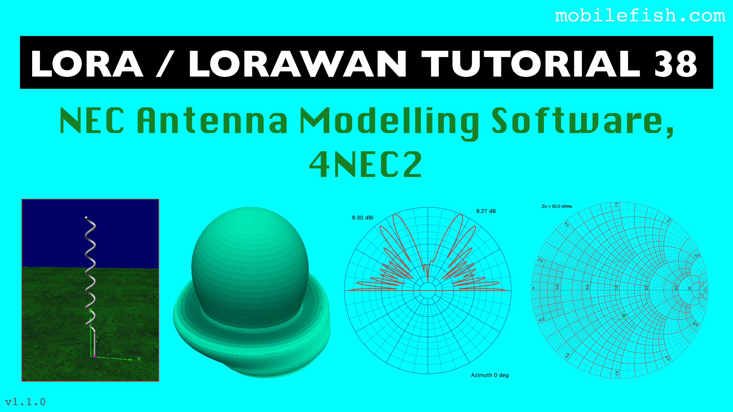
LORA / LORAWAN TUTORIAL 38 mobilefish.com NEC Antenna Modelling Software, 4NEC2 v1.1.0
LORA / LORAWAN TUTORIAL 38mobilefish.com
NEC Antenna Modelling Software, 4NEC2
v1.1.0

INTROmobilefish.com
• In this tutorial I will explain what a NEC antenna modelling software is and how to use the 4NEC2 antenna modelling software.

WHAT IS THE PURPOSE OF ANT. MODELLING S/Wmobilefish.com
• On Internet and YouTube you can find tutorials how to build certain antennas.
• But often I wonder what is the performance of these antennas? What if I use a slightly different wire diameter or slightly change the length of a particular wire? Will these changes impact the antenna performance significantly of not at all?
• Using an antenna modelling software can help you to answer these questions without having to build the actual antenna right away.
• NEC (Numerical Electromagnetics Code) is a popular antenna modelling system for wire and surface antennas and simulates the electromagnetic response of antennas and metal structures.
WHAT IS THE PURPOSE OF ANT. MODELLING S/Wmobilefish.com
• The accuracy of the calculation depends on how well you model the antenna and the information you provide with regard to the ground and wire conductivity.
• But be aware, in the real world using the actual antenna, the result will be slightly different compared to the simulation. This is caused by reflections, weather conditions, where the antenna is mounted etc.
WHAT IS THE PURPOSE OF ANT. MODELLING S/Wmobilefish.com
• For the LoRa/LoRaWAN tutorials I have build several simple antennas, which I will demonstrate in upcoming tutorials, and I have model these antennas. To my surprise most of these antennas behaves as predicted by the antenna modelling software.
• If you are planning to build your own antenna I highly recommend that you first model your antenna before actually building it. It will safe you time, money and frustration.
• For example I used a steel coat hanger with a 3 mm wire diameter to build an antenna. I spend 2 hours to remove the plastic coating and cutting the antenna elements to their correct lengths.
• When I finished building the antenna I used the N1201SA antenna analyser to check the VSWR.
WHAT IS THE PURPOSE OF ANT. MODELLING S/Wmobilefish.com
• The result was not great, my antenna has a VSWR of 3.
• I decided to use an antenna modelling software to check what I have done wrong.
• By changing certain antenna parameters in the model I concluded that I used the wrong wire diameter. Instead of 3 mm I should have used a wire diameter of 1.8 mm to get a VSWR less than 2.
• The antenna modelling software also provides the horizontal and vertical antenna radiation patterns. These radiation patterns are just as important as the VSWR.
• What if the main lobe is pointing upwards instead of sideways. If your sensors and gateways are located on a flat area than this antenna will not perform great.
NEC ANTENNA MODELLING SOFTWAREmobilefish.com
• Here are a few NEC antenna modelling software:
• EZNEC - Available for Windows. It has a free and a paid version. The free version has a 20 segments limit.http://www.eznec.com
• 4NEC2 - Available for Windows and its free. This tool has many options. https://www.qsl.net/4nec2/
• cocoaNEC - Available for MAC OSX and its free. This tool has limited options.http://www.w7ay.net/site/Applications/cocoaNEC/
NEC ANTENNA MODELLING SOFTWAREmobilefish.com
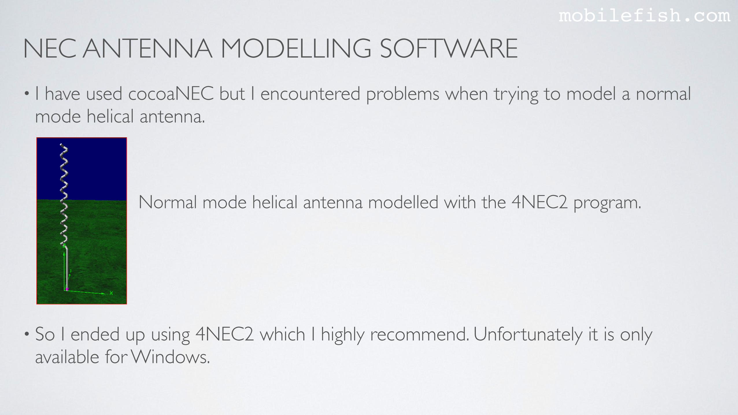
• I have used cocoaNEC but I encountered problems when trying to model a normal mode helical antenna.
• So I ended up using 4NEC2 which I highly recommend. Unfortunately it is only available for Windows.
Normal mode helical antenna modelled with the 4NEC2 program.
NECmobilefish.com
• The previous mentioned 3 antenna modelling software uses the NEC-2 (Numerical Electromagnetics Code) engine which does all the calculations.
• NEC was developed by the Lawrence Livermore National Laboratory in the 1970s and is an antenna modelling system for wire and surface antennas.
• More information about NEC-2: https://www.nec2.org
• The NEC2 documentation is composed of three sections:Part I: NEC Program Description - Theory, https://www.nec2.org/other/nec2prt1.pdfPart II: NEC Program Description - Code,http://www.radio-bip.qc.ca/NEC2/nec2prt2.pdfPart III: NEC User's Guide, https://www.nec2.org/other/nec2prt3.pdfPart III is the documentation you need.
NECmobilefish.com
• NEC2 quick reference:https://www.mobilefish.com/download/lora/nec2_quick_reference.pdf
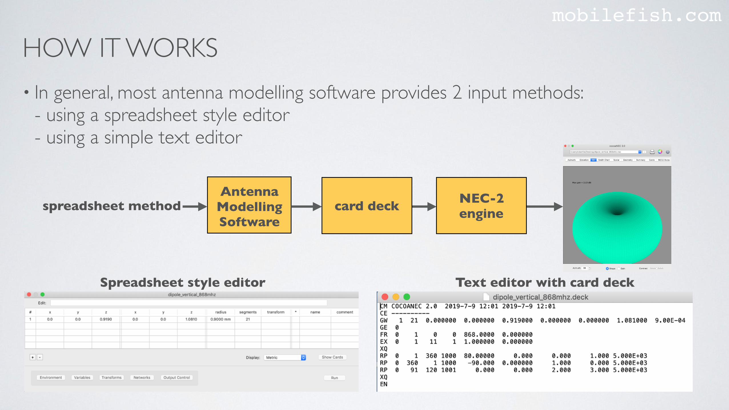
HOW IT WORKSmobilefish.com
• In general, most antenna modelling software provides 2 input methods:- using a spreadsheet style editor- using a simple text editor
AntennaModellingSoftware
spreadsheet method card deck NEC-2 engine
Spreadsheet style editor Text editor with card deck

HOW IT WORKSmobilefish.com
• There are antenna modelling software available (e.g. 4NEC2) where you can model the antenna by drawing it, using a Graphical User Interface (GUI).

mobilefish.com
4NEC2 ANTENNA MODELLINGDEMONSTRATION
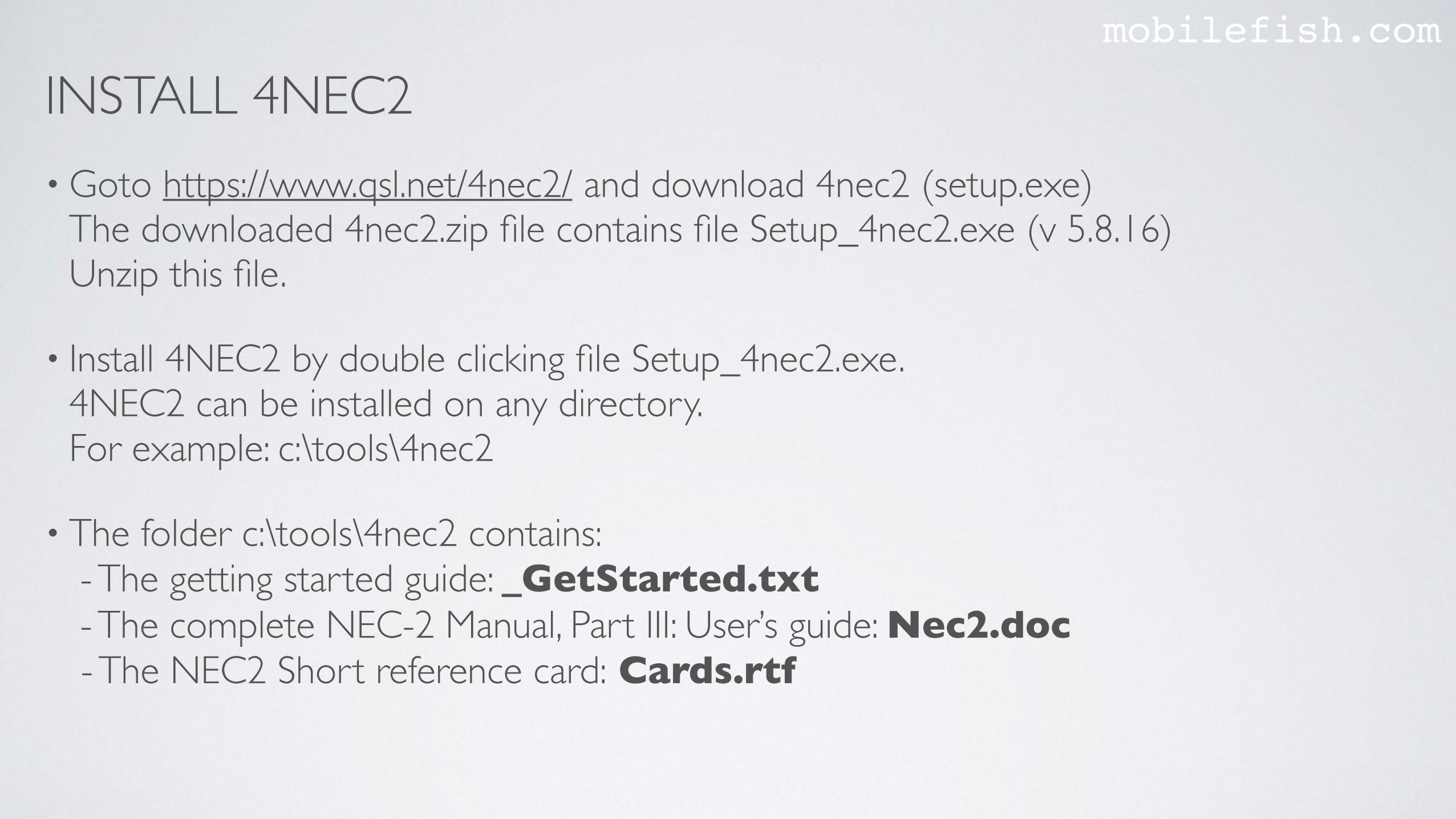
INSTALL 4NEC2mobilefish.com
• Goto https://www.qsl.net/4nec2/ and download 4nec2 (setup.exe)The downloaded 4nec2.zip file contains file Setup_4nec2.exe (v 5.8.16)Unzip this file.
• Install 4NEC2 by double clicking file Setup_4nec2.exe.4NEC2 can be installed on any directory.For example: c:\tools\4nec2
• The folder c:\tools\4nec2 contains: - The getting started guide: _GetStarted.txt - The complete NEC-2 Manual, Part III: User’s guide: Nec2.doc - The NEC2 Short reference card: Cards.rtf
INSTALL 4NEC2mobilefish.com
• The complete 4NEC2 help in document format 4nec2/exe/4nec2.rtf
• Many antenna model examples: 4nec2/models
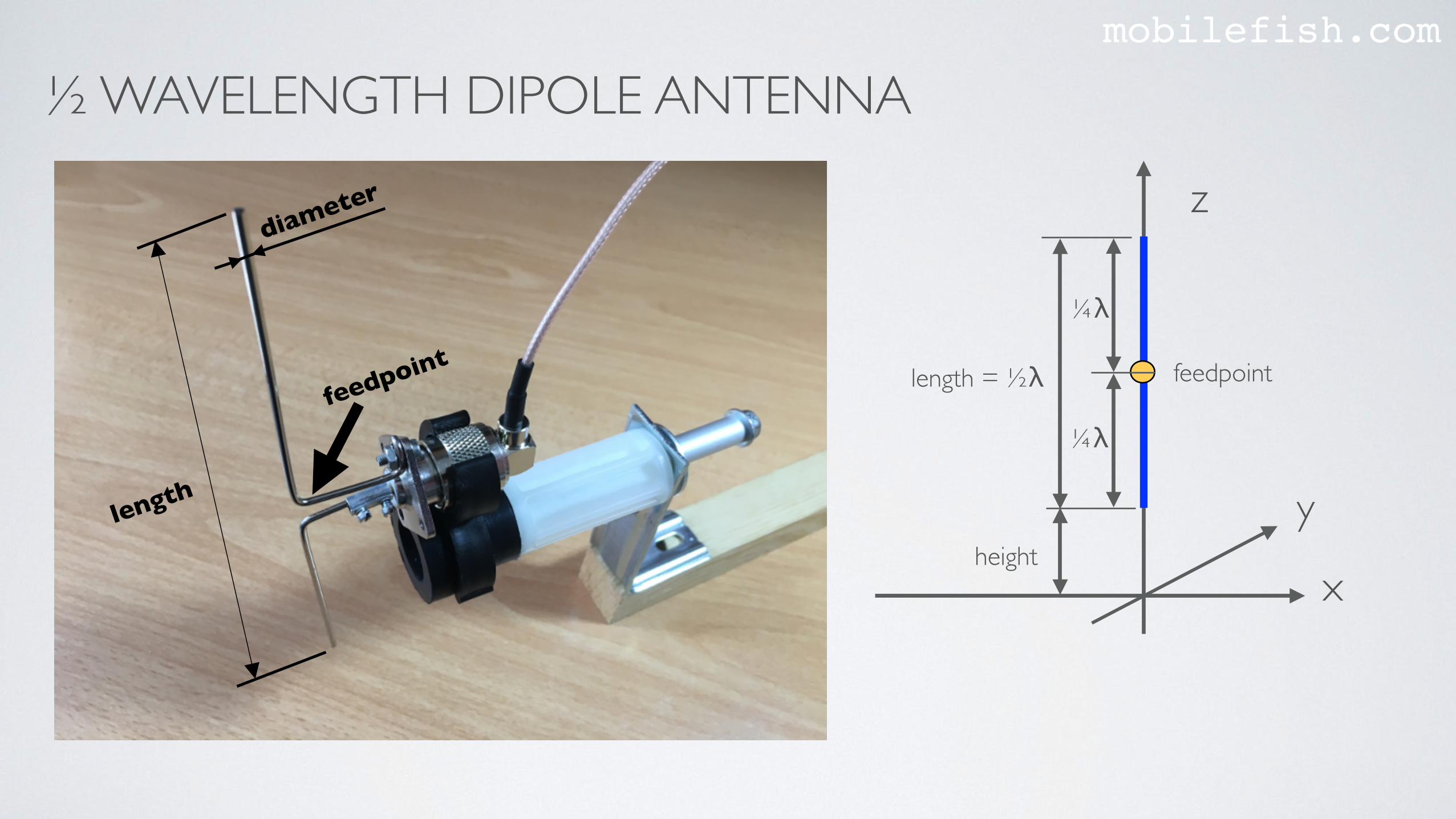
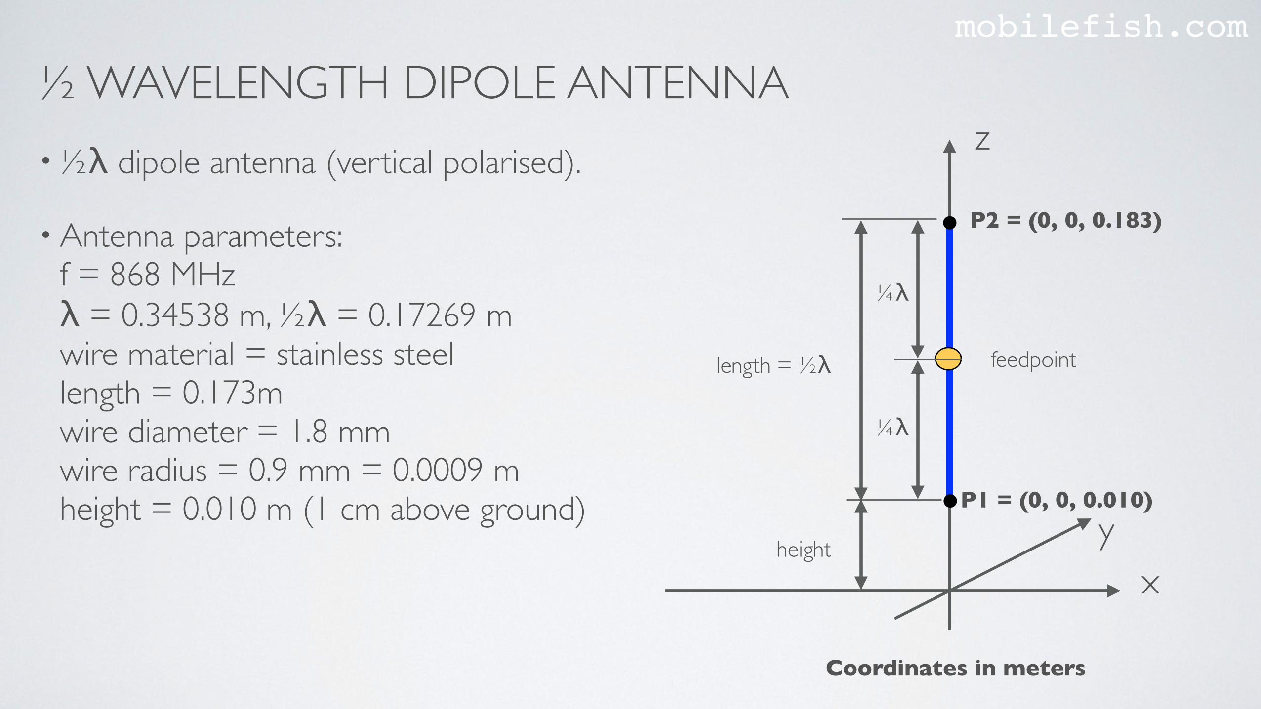
½ WAVELENGTH DIPOLE ANTENNAmobilefish.com
length
feedpoint
x
y
z
length = ½λ
height
feedpoint
¼λ
¼λ
diameter
½ WAVELENGTH DIPOLE ANTENNAmobilefish.com
•½λ dipole antenna (vertical polarised).
• Antenna parameters:f = 868 MHz λ = 0.34538 m, ½λ = 0.17269 m wire material = stainless steellength = 0.173mwire diameter = 1.8 mmwire radius = 0.9 mm = 0.0009 m height = 0.010 m (1 cm above ground) x
y
z
length = ½λ
height
feedpoint
¼λ
¼λ
P1 = (0, 0, 0.010)
P2 = (0, 0, 0.183)
Coordinates in meters
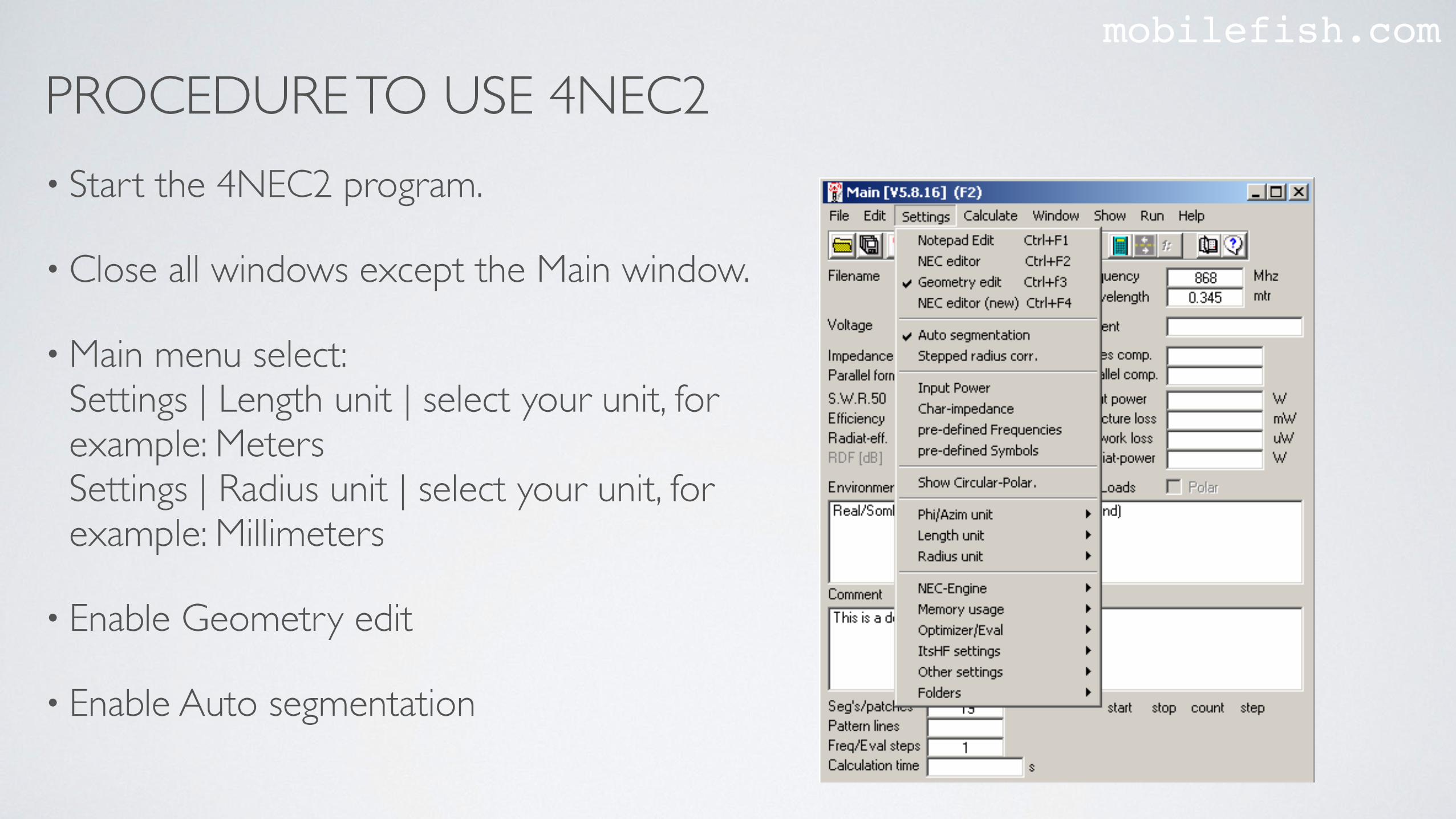
PROCEDURE TO USE 4NEC2mobilefish.com
• Start the 4NEC2 program.
• Close all windows except the Main window.
• Main menu select: Settings | Length unit | select your unit, for example: MetersSettings | Radius unit | select your unit, for example: Millimeters
• Enable Geometry edit
• Enable Auto segmentation
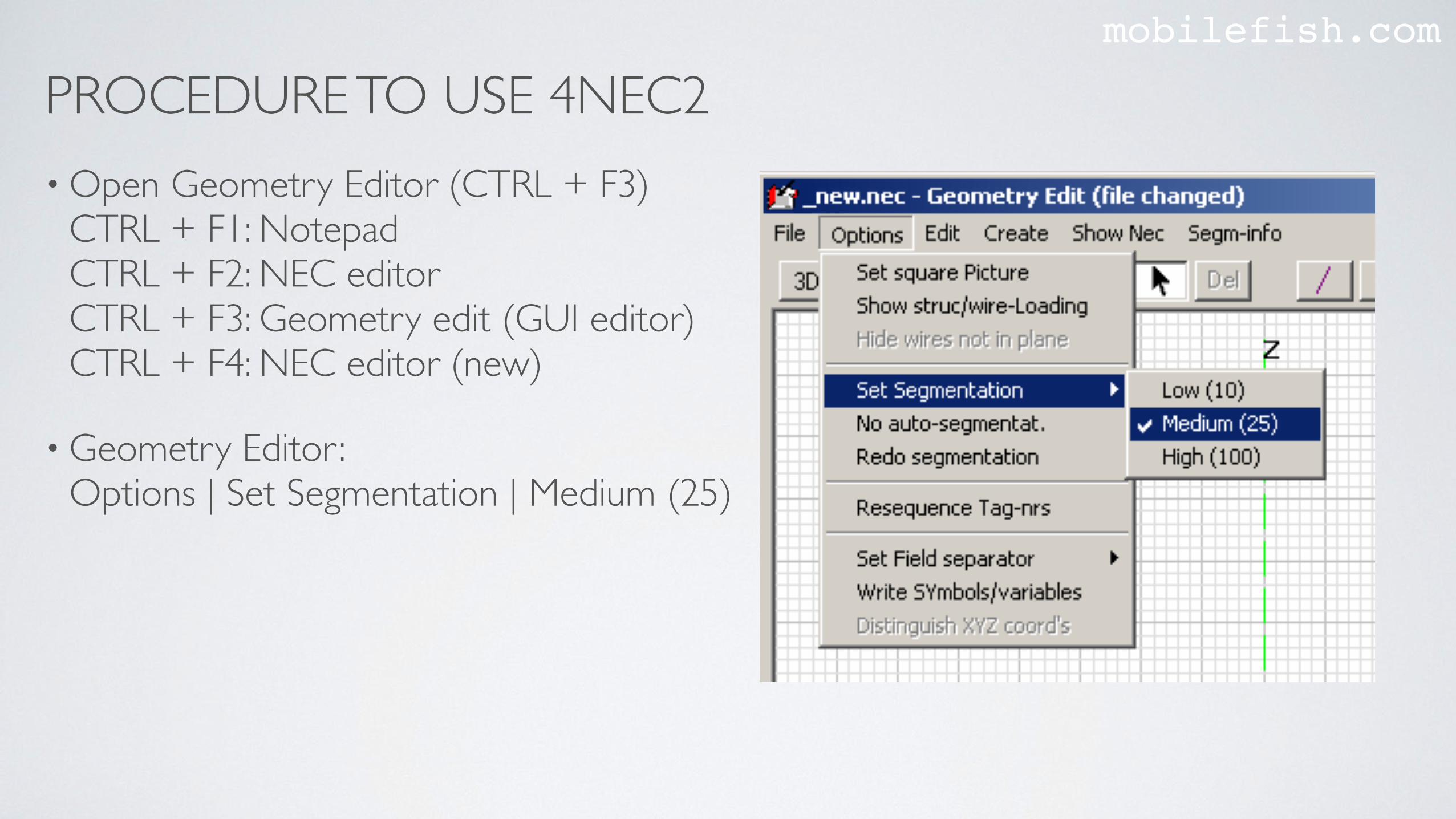
PROCEDURE TO USE 4NEC2mobilefish.com
• Open Geometry Editor (CTRL + F3) CTRL + F1: NotepadCTRL + F2: NEC editor CTRL + F3: Geometry edit (GUI editor) CTRL + F4: NEC editor (new)
• Geometry Editor :Options | Set Segmentation | Medium (25)
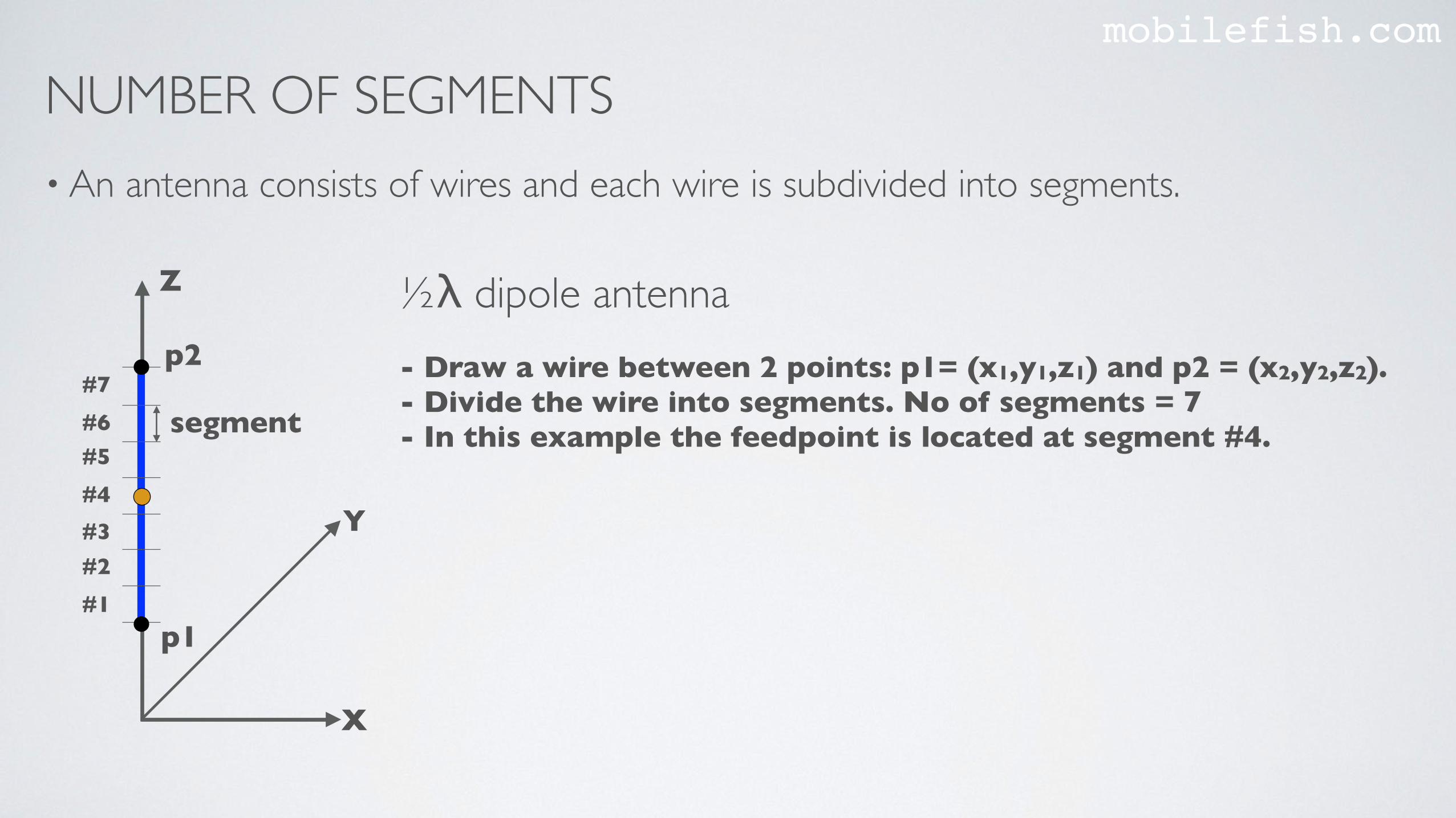
NUMBER OF SEGMENTSmobilefish.com
• An antenna consists of wires and each wire is subdivided into segments.
- Draw a wire between 2 points: p1= (x1,y1,z1) and p2 = (x2,y2,z2).- Divide the wire into segments. No of segments = 7- In this example the feedpoint is located at segment #4.
½λ dipole antennaZ
X
Y
p1
p2
segment
#1#2
#7#6#5#4#3
NUMBER OF SEGMENTSmobilefish.com
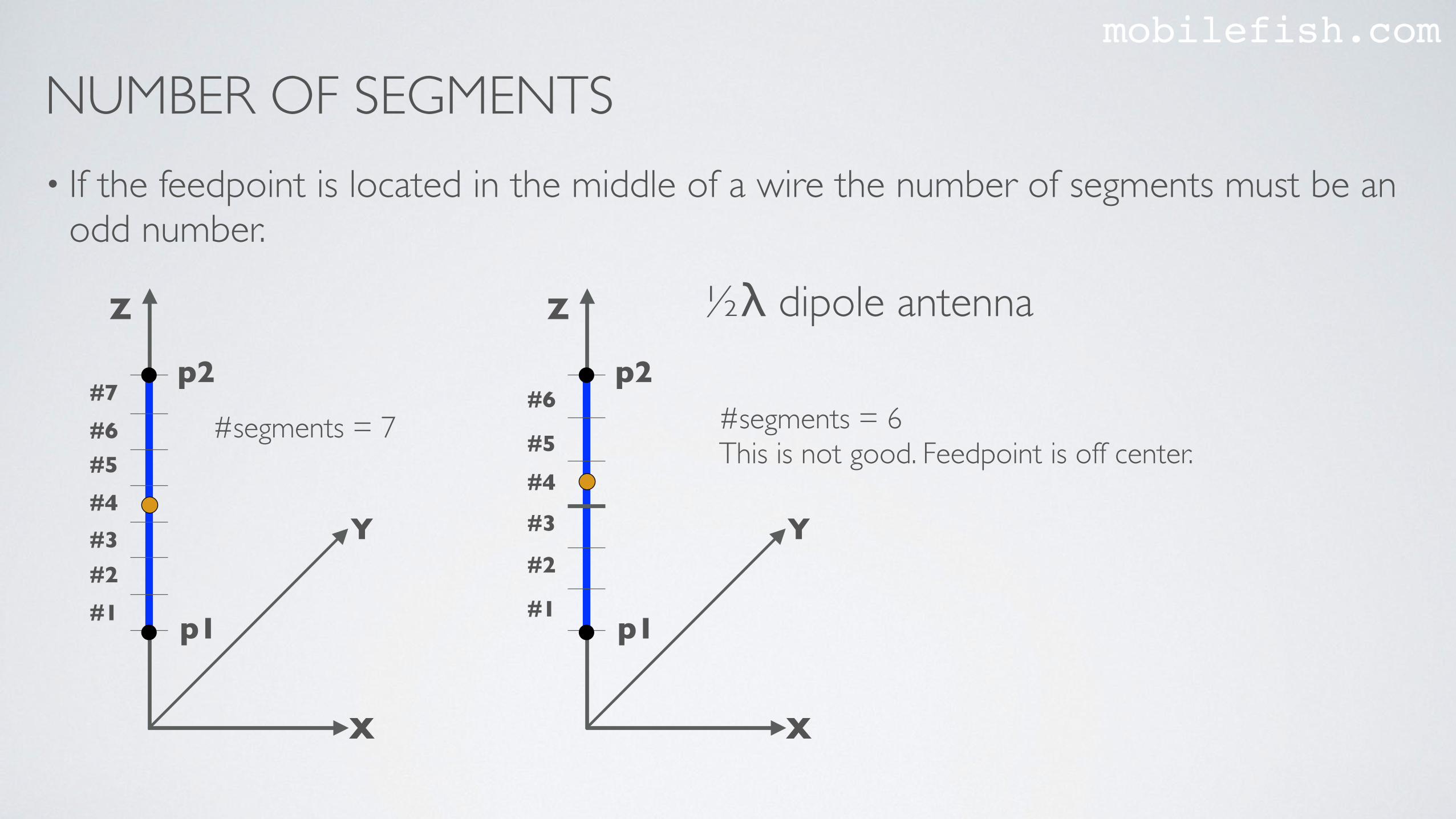
• If the feedpoint is located in the middle of a wire the number of segments must be an odd number.
Z
X
Y
p1
p2
#1
#2
#6
#5#4
#3
Z
X
Y
p1
p2
#1#2
#7#6#5#4#3
#segments = 7 #segments = 6This is not good. Feedpoint is off center.
½λ dipole antenna
NUMBER OF SEGMENTSmobilefish.com
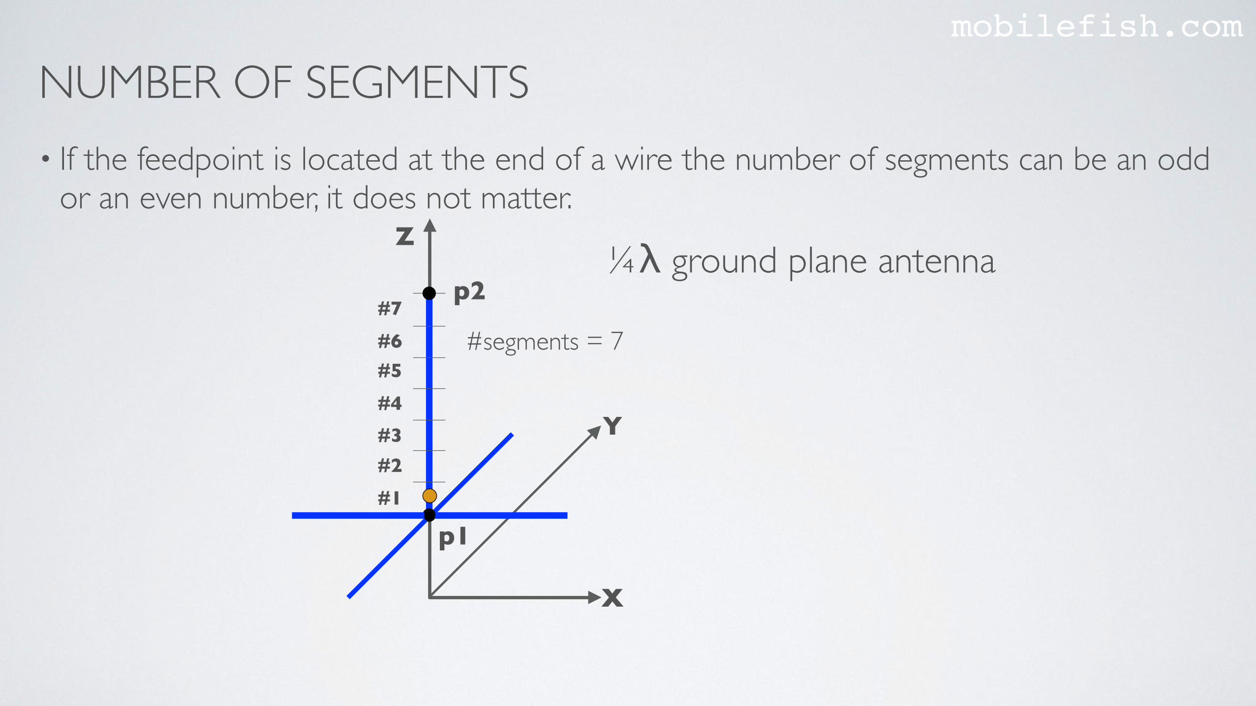
• If the feedpoint is located at the end of a wire the number of segments can be an odd or an even number, it does not matter.
Z
X
Y
p1
p2
#1#2
#7#6#5#4#3
#segments = 7
¼λ ground plane antenna
NUMBER OF SEGMENTSmobilefish.com
• You can let the 4NEC2 program to automatically calculate the number of segments.
• But you can do it yourself, but it is not recommended.There are certain rules you must follow.
• If the number of segments is too low the calculations are not accurate. If it is too high the calculations takes a lot of time.
NUMBER OF SEGMENTSmobilefish.com
• The length of each segment must be between 5% and 10% of the wavelength.
• If the ratio of segment length to wire radius is greater than 8 the NEC engine simulates the current flow in the wire as a very thin current thread. The NEC engine uses the default "Thin Wire Kernel” (Do not use EK card)
• If the ratio is between 2 and 8 the NEC engine should simulate the current to be evenly distributed on the circumference of the wire for a more accurate result. In this situation you should use the EK card (Extended Thin Wire Kernel).
• Never make the ratio go below 2.
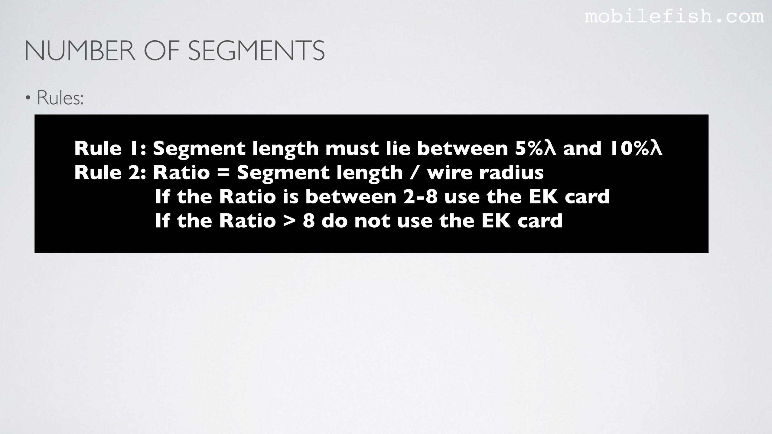
NUMBER OF SEGMENTSmobilefish.com
• Rules:
Rule 1: Segment length must lie between 5%λ and 10%λRule 2: Ratio = Segment length / wire radius If the Ratio is between 2-8 use the EK card If the Ratio > 8 do not use the EK card
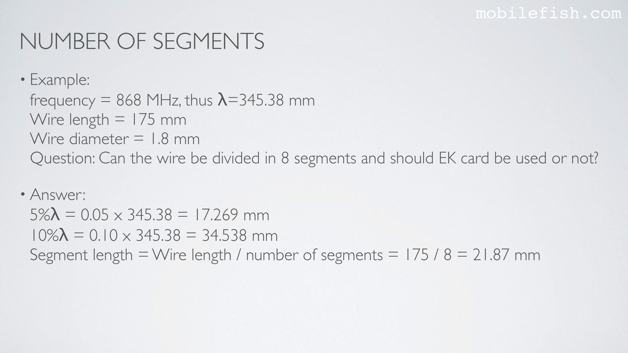
NUMBER OF SEGMENTSmobilefish.com
• Example: frequency = 868 MHz, thus λ=345.38 mmWire length = 175 mm Wire diameter = 1.8 mmQuestion: Can the wire be divided in 8 segments and should EK card be used or not?
• Answer:5%λ = 0.05 x 345.38 = 17.269 mm 10%λ = 0.10 x 345.38 = 34.538 mm Segment length = Wire length / number of segments = 175 / 8 = 21.87 mm
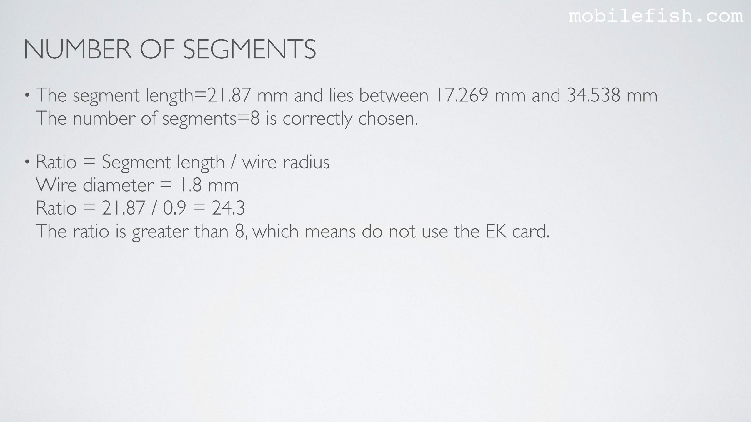
NUMBER OF SEGMENTSmobilefish.com
• The segment length=21.87 mm and lies between 17.269 mm and 34.538 mm The number of segments=8 is correctly chosen.
• Ratio = Segment length / wire radius Wire diameter = 1.8 mmRatio = 21.87 / 0.9 = 24.3The ratio is greater than 8, which means do not use the EK card.
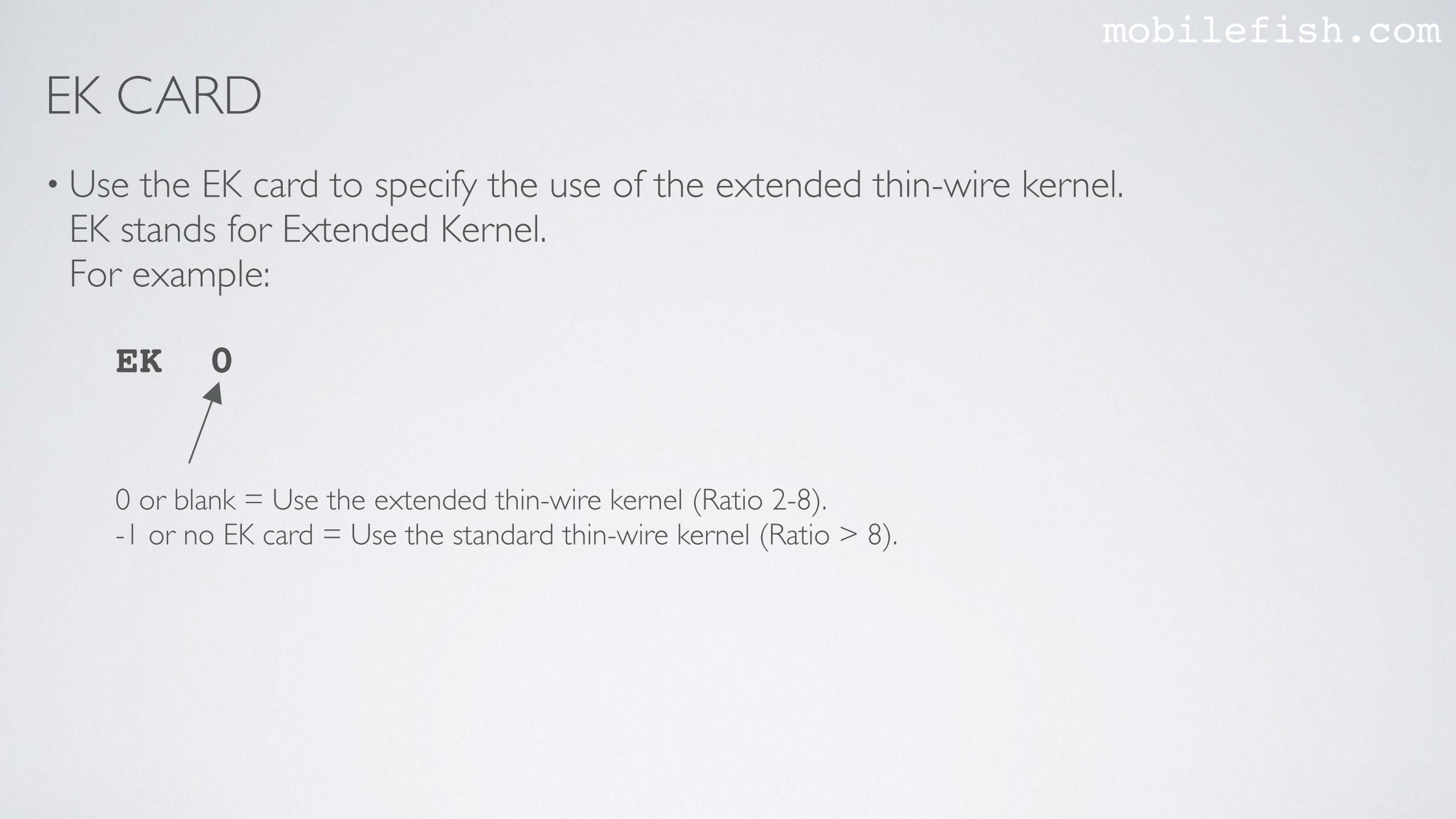
EK CARDmobilefish.com
• Use the EK card to specify the use of the extended thin-wire kernel. EK stands for Extended Kernel.For example:
0 or blank = Use the extended thin-wire kernel (Ratio 2-8).-1 or no EK card = Use the standard thin-wire kernel (Ratio > 8).
EK 0

PROCEDURE TO USE 4NEC2mobilefish.com
• Geometry Editor select:Options | No-auto-segmentation DO NOT SELECT Options | Set Field separator | TABOptions | Write Symbols / variables DO NOT SELECT File | New File | Save As | dipole_demo.nec
• Set display frequency: 868 MHz (Press Enter) Save file and open dipole_demo.nec

CE CARDmobilefish.com
• Use the CE card to specify the end of the comment section.CE stands for Comment End.For example:
CE
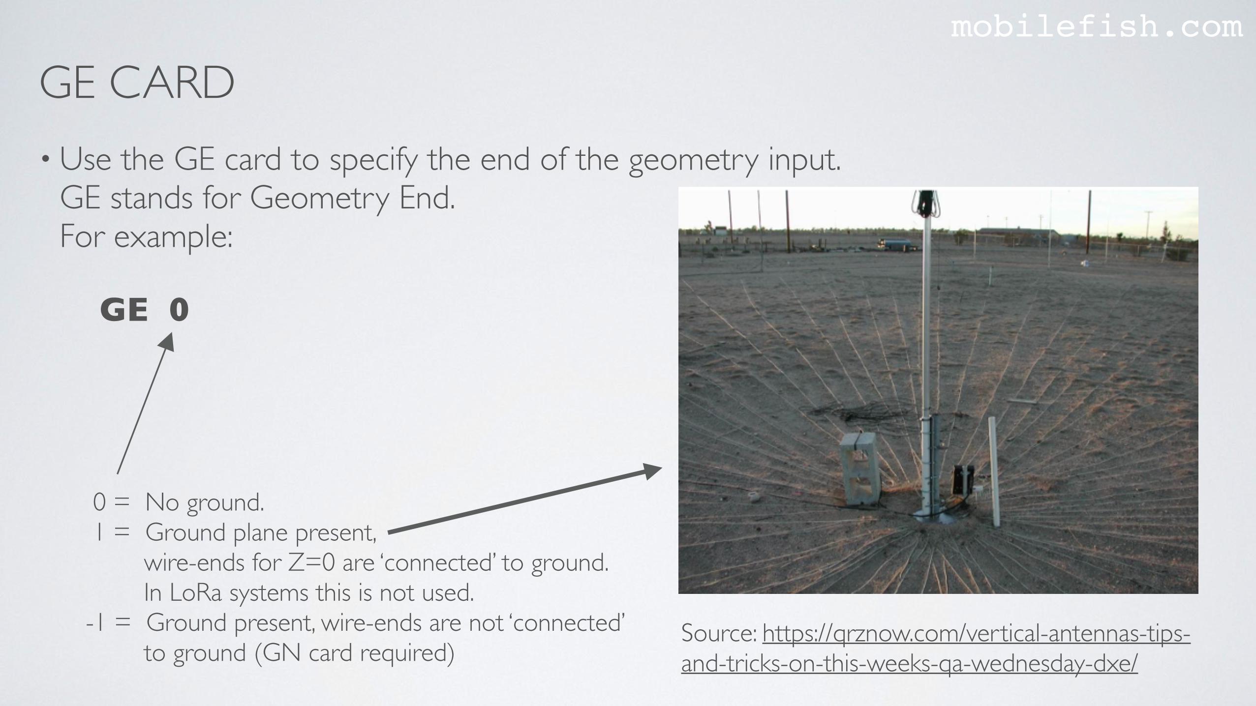
GE CARDmobilefish.com
• Use the GE card to specify the end of the geometry input. GE stands for Geometry End.For example:
GE 0
0 = No ground. 1 = Ground plane present, wire-ends for Z=0 are ‘connected’ to ground. In LoRa systems this is not used.-1 = Ground present, wire-ends are not ‘connected’ to ground (GN card required)
Source: https://qrznow.com/vertical-antennas-tips-and-tricks-on-this-weeks-qa-wednesday-dxe/
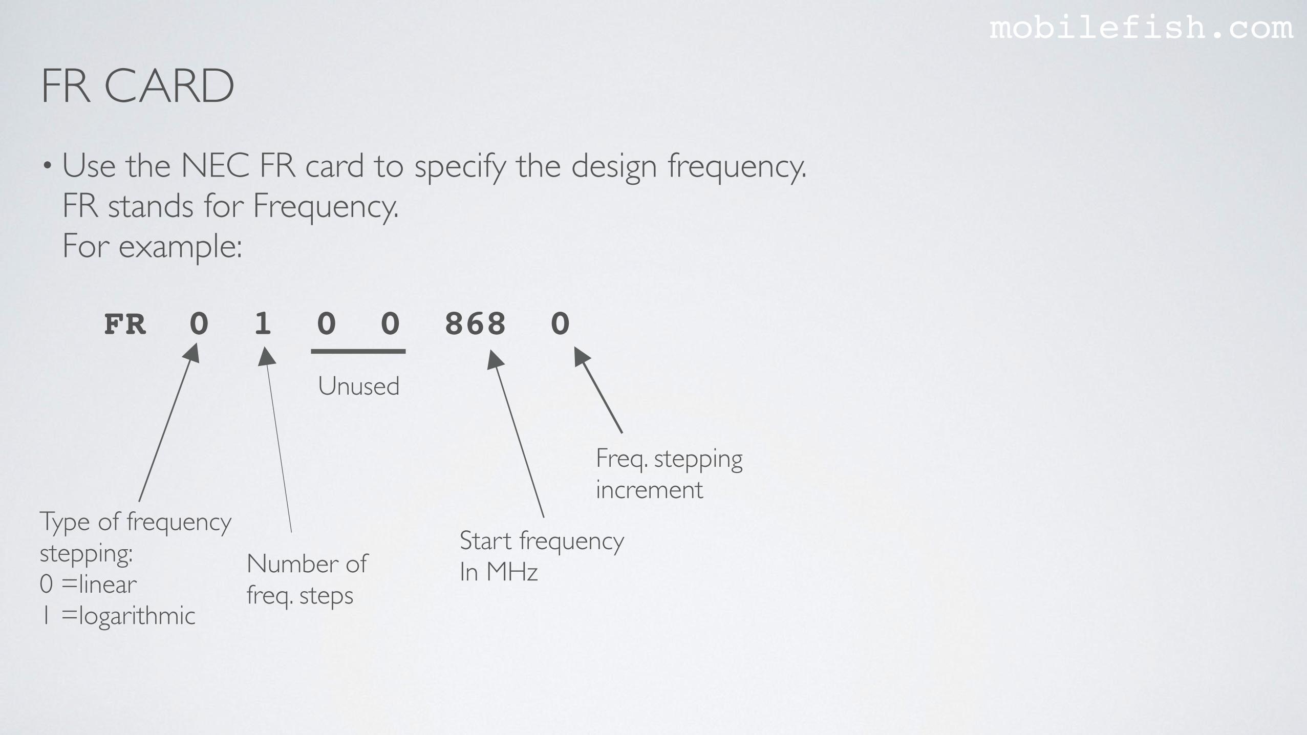
FR CARDmobilefish.com
• Use the NEC FR card to specify the design frequency. FR stands for Frequency.For example:
Unused
Number of freq. steps
Type of frequency stepping:0 =linear1 =logarithmic
FR 0 1 0 0 868 0
Start frequencyIn MHz
Freq. stepping increment
PROCEDURE TO USE 4NEC2mobilefish.com
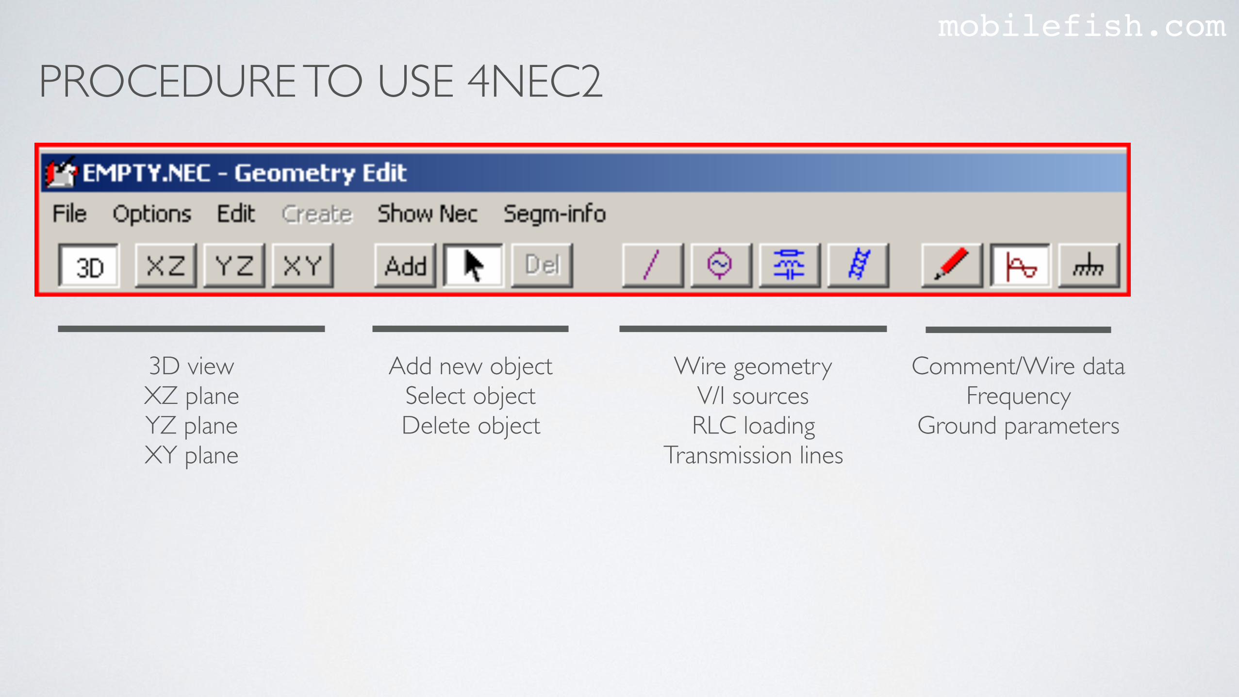
3D viewXZ planeYZ planeXY plane
Add new objectSelect objectDelete object
Wire geometryV/I sourcesRLC loading
Transmission lines
Comment/Wire dataFrequency
Ground parameters
PROCEDURE TO USE 4NEC2mobilefish.com
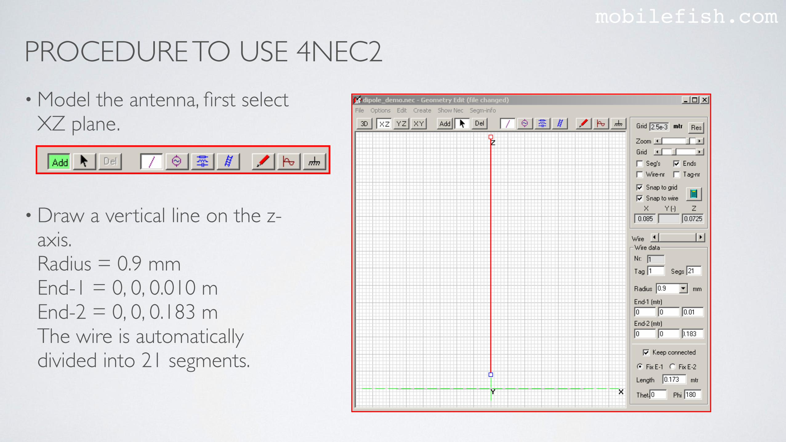
• Model the antenna, first select XZ plane.
• Draw a vertical line on the z-axis.Radius = 0.9 mmEnd-1 = 0, 0, 0.010 m End-2 = 0, 0, 0.183 m The wire is automatically divided into 21 segments.
PROCEDURE TO USE 4NEC2mobilefish.com
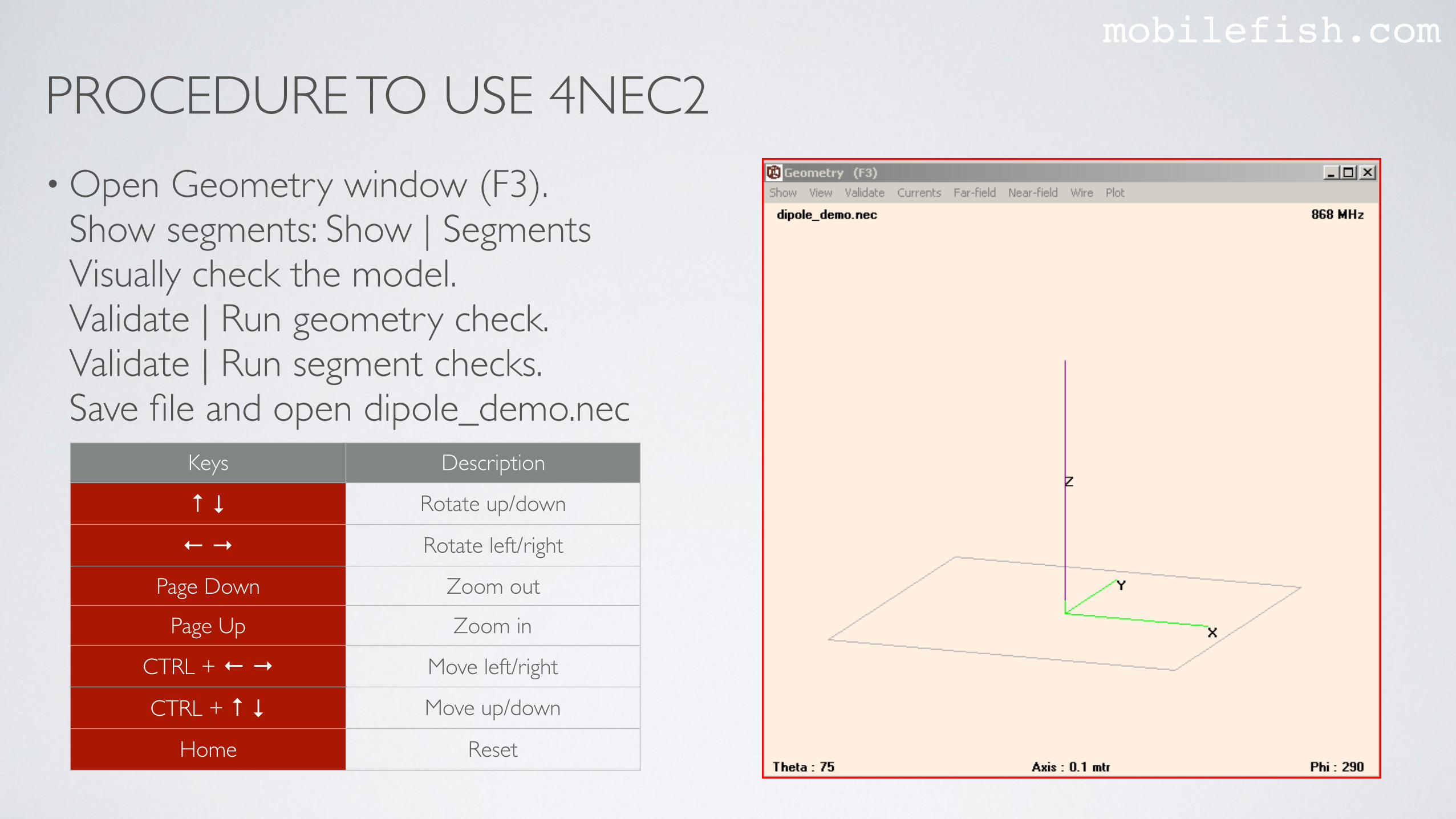
• Open Geometry window (F3).Show segments: Show | Segments Visually check the model.Validate | Run geometry check.Validate | Run segment checks.Save file and open dipole_demo.nec
Keys Description
↑ ↓ Rotate up/down
← → Rotate left/right
Page Down Zoom out
Page Up Zoom in
CTRL + ← → Move left/right
CTRL + ↑ ↓ Move up/down
Home Reset
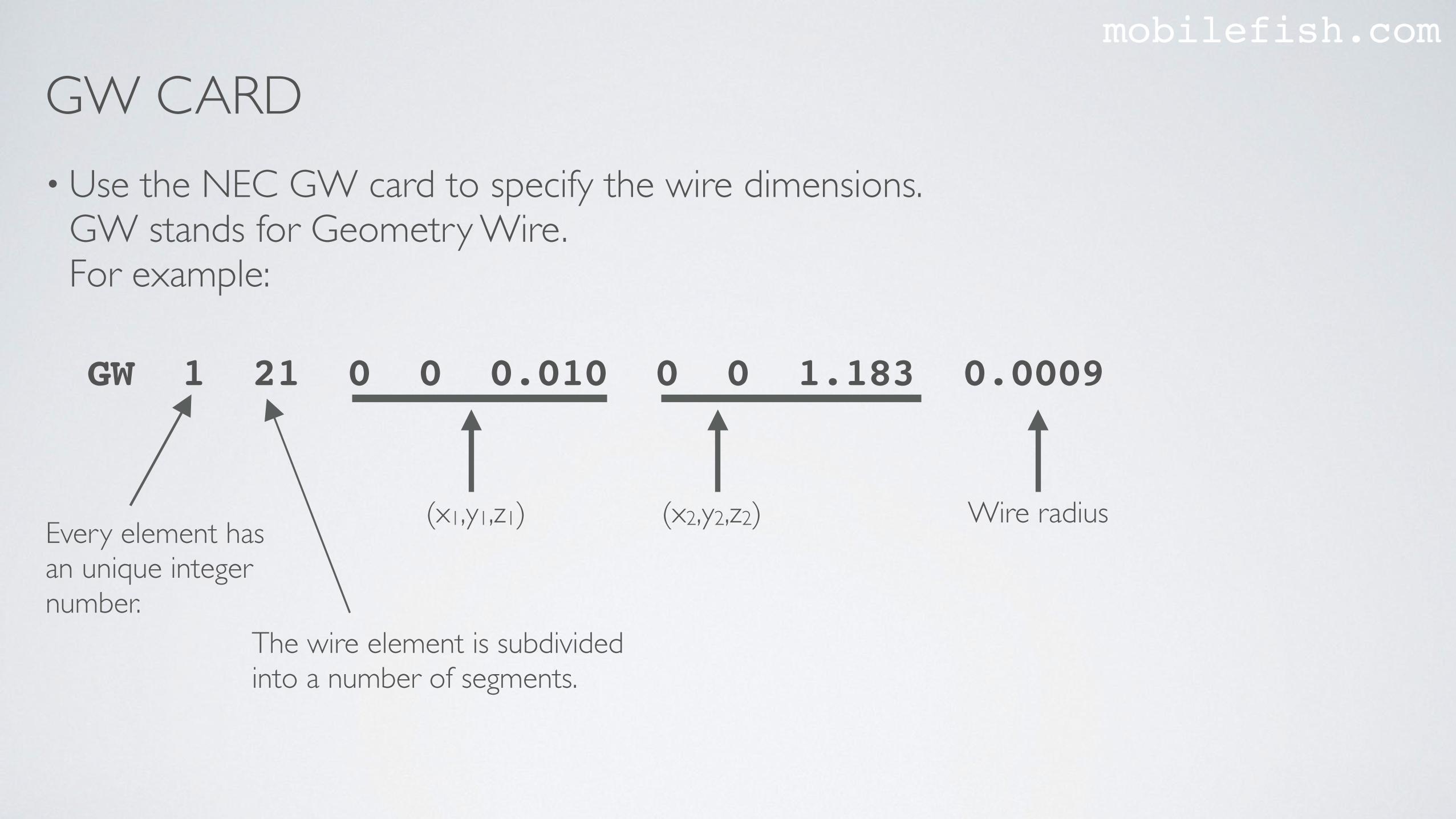
GW CARDmobilefish.com
• Use the NEC GW card to specify the wire dimensions.GW stands for Geometry Wire.For example:
(x1,y1,z1)
The wire element is subdivided into a number of segments.
Every element has an unique integer number.
GW 1 21 0 0 0.010 0 0 1.183 0.0009
(x2,y2,z2) Wire radius
PROCEDURE TO USE 4NEC2mobilefish.com
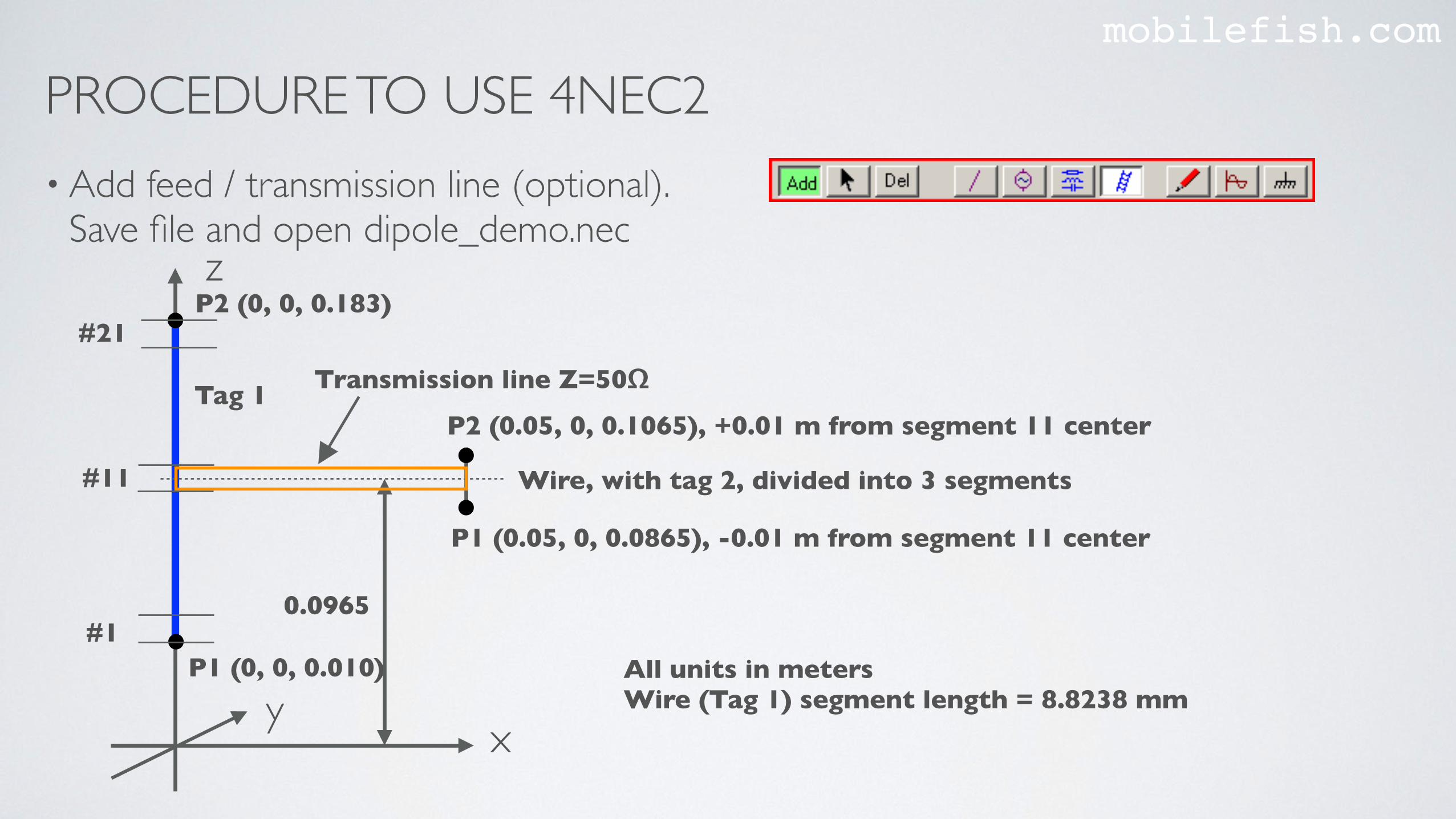
• Add feed / transmission line (optional). Save file and open dipole_demo.nec
xy
z
P1 (0, 0, 0.010)#1
#21
#11
P1 (0.05, 0, 0.0865), -0.01 m from segment 11 center
P2 (0, 0, 0.183)
P2 (0.05, 0, 0.1065), +0.01 m from segment 11 center
All units in metersWire (Tag 1) segment length = 8.8238 mm
0.0965
Wire, with tag 2, divided into 3 segments
Tag 1 Transmission line Z=50Ω
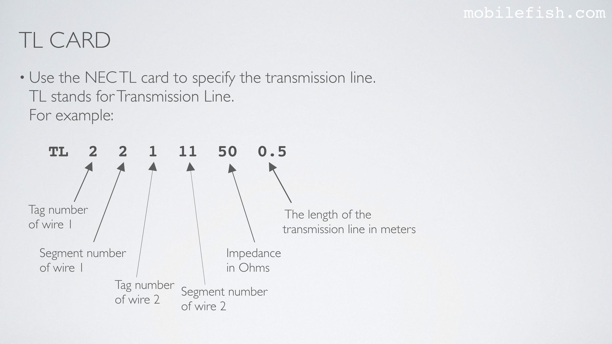
TL CARDmobilefish.com
• Use the NEC TL card to specify the transmission line.TL stands for Transmission Line.For example:
Segment numberof wire 1
Tag number of wire 1
TL 2 2 1 11 50 0.5
Impedance in Ohms
The length of the transmission line in meters
Tag number of wire 2 Segment number
of wire 2
PROCEDURE TO USE 4NEC2mobilefish.com
• In all my antenna models, I never model the transmission line. For demonstration purpose I have shown how this is done in case you need it. Delete the transmission line and wire tag 2.
PROCEDURE TO USE 4NEC2mobilefish.com
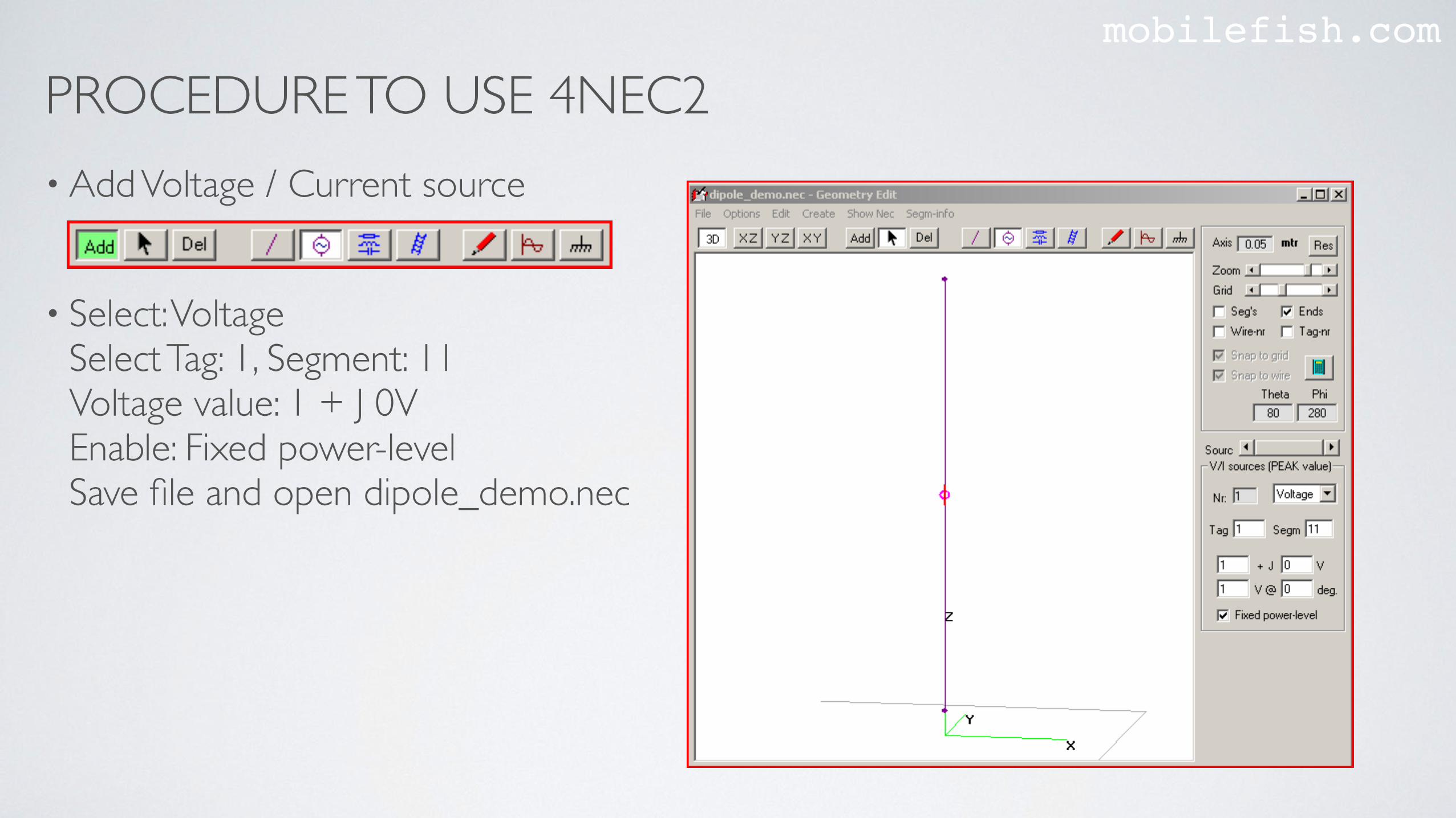
• Add Voltage / Current source
• Select: VoltageSelect Tag: 1, Segment: 11Voltage value: 1 + J 0V Enable: Fixed power-levelSave file and open dipole_demo.nec
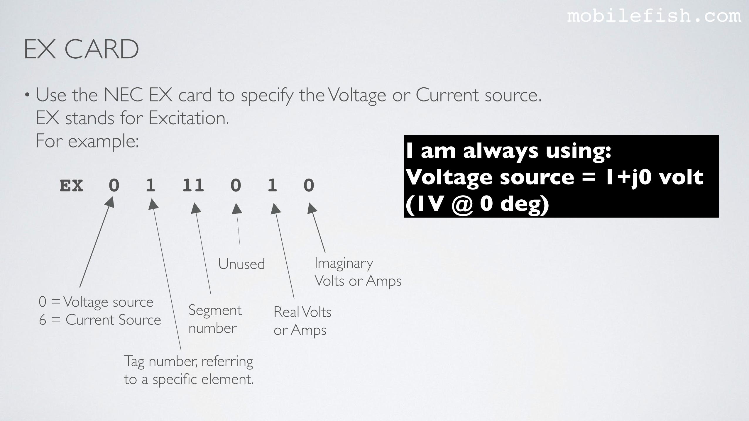
EX CARDmobilefish.com
• Use the NEC EX card to specify the Voltage or Current source.EX stands for Excitation.For example:
Unused
Tag number, referring to a specific element.
0 = Voltage source6 = Current Source Segment
number
EX 0 1 11 0 1 0
Real Volts or Amps
ImaginaryVolts or Amps
I am always using:Voltage source = 1+j0 volt (1V @ 0 deg)
PROCEDURE TO USE 4NEC2mobilefish.com
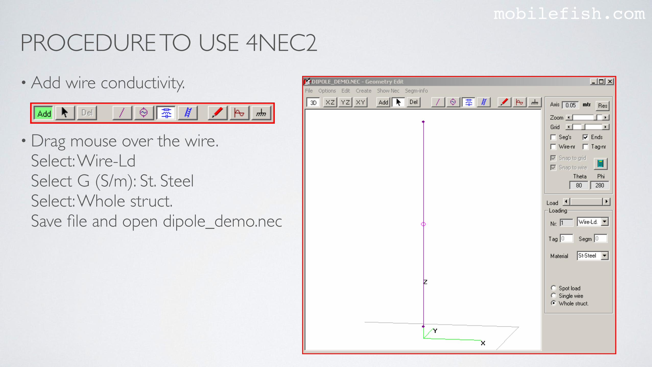
• Add wire conductivity.
• Drag mouse over the wire.Select: Wire-LdSelect G (S/m): St. Steel Select: Whole struct.Save file and open dipole_demo.nec
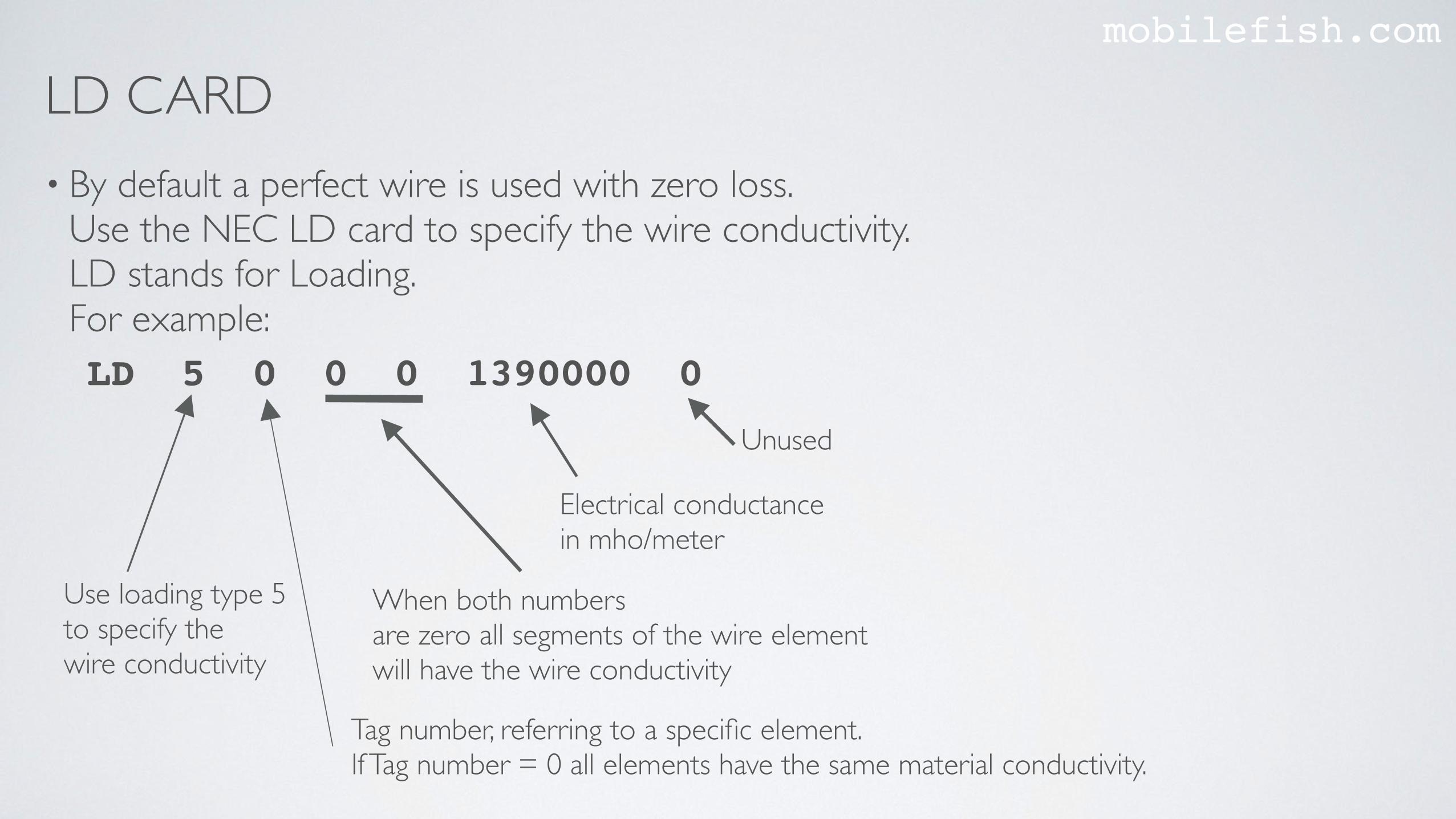
LD CARDmobilefish.com
• By default a perfect wire is used with zero loss.Use the NEC LD card to specify the wire conductivity.LD stands for Loading.For example:
Electrical conductancein mho/meter
Tag number, referring to a specific element.If Tag number = 0 all elements have the same material conductivity.
Use loading type 5 to specify the wire conductivity
When both numbers are zero all segments of the wire element will have the wire conductivity
LD 5 0 0 0 1390000 0
Unused
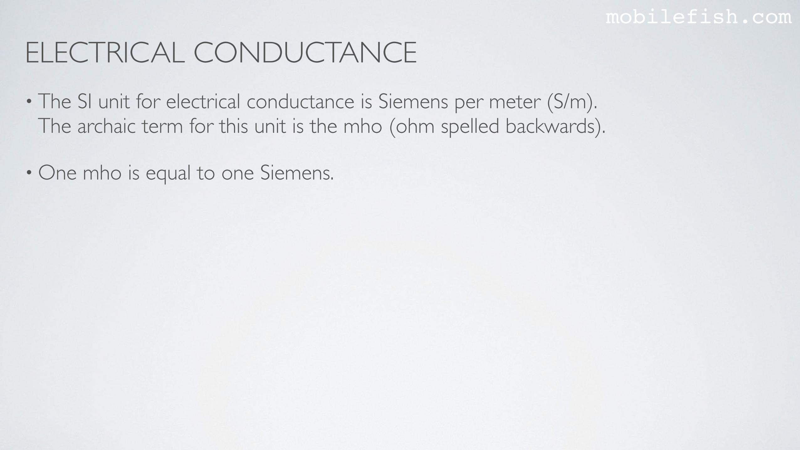
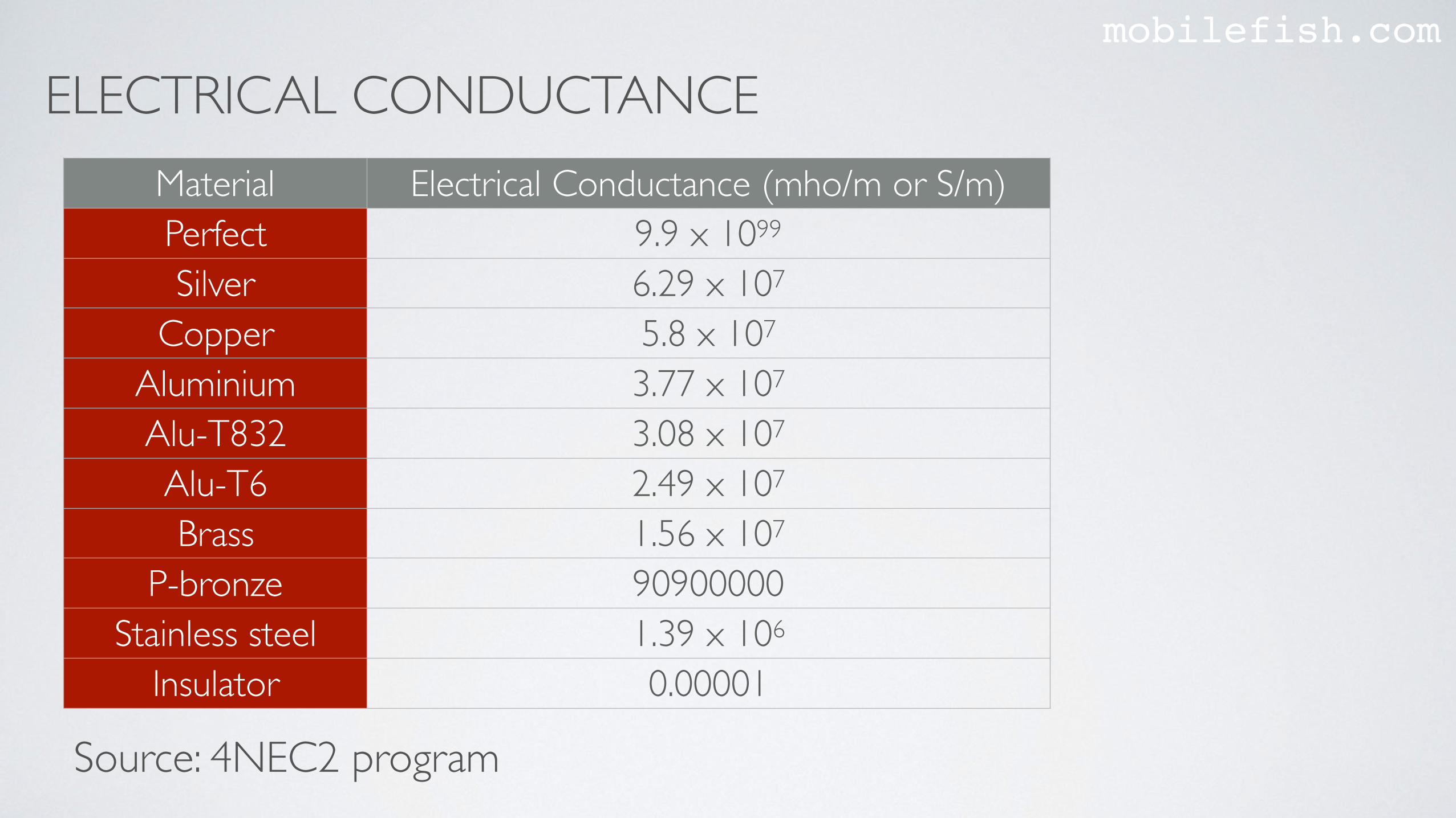
ELECTRICAL CONDUCTANCEmobilefish.com
• The SI unit for electrical conductance is Siemens per meter (S/m). The archaic term for this unit is the mho (ohm spelled backwards).
• One mho is equal to one Siemens.
ELECTRICAL CONDUCTANCEmobilefish.com
Material Electrical Conductance (mho/m or S/m)Perfect 9.9 x 1099
Silver 6.29 x 10⁷
Copper 5.8 x 10⁷
Aluminium 3.77 x 10⁷
Alu-T832 3.08 x 10⁷
Alu-T6 2.49 x 10⁷
Brass 1.56 x 10⁷
P-bronze 90900000Stainless steel 1.39 x 10⁶
Insulator 0.00001
Source: 4NEC2 program

PROCEDURE TO USE 4NEC2mobilefish.com
• Specify ground parameters
• Select Type: Real groundSelect: City industrial areaSave file and open dipole_demo.nec
PROCEDURE TO USE 4NEC2mobilefish.com
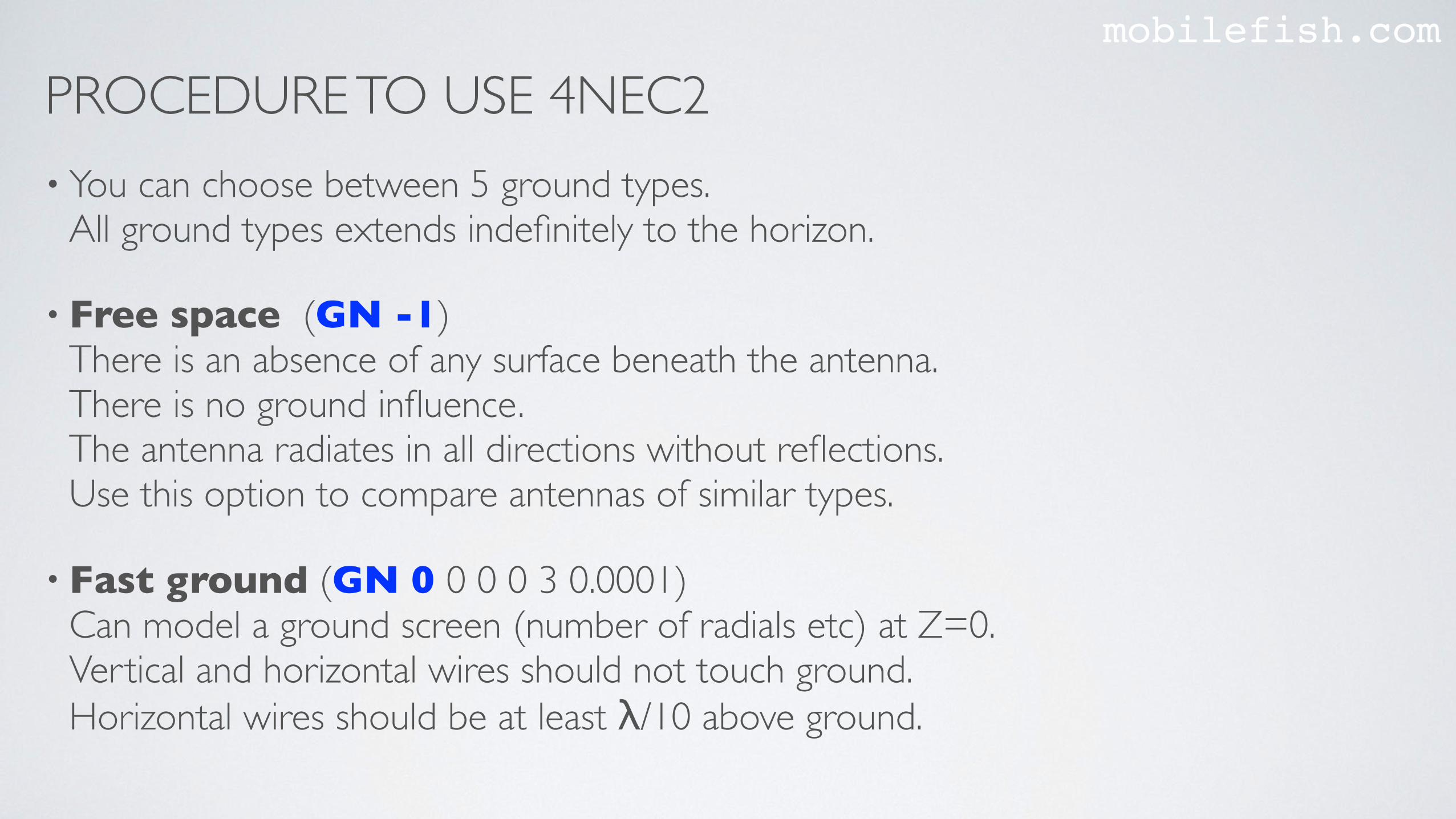
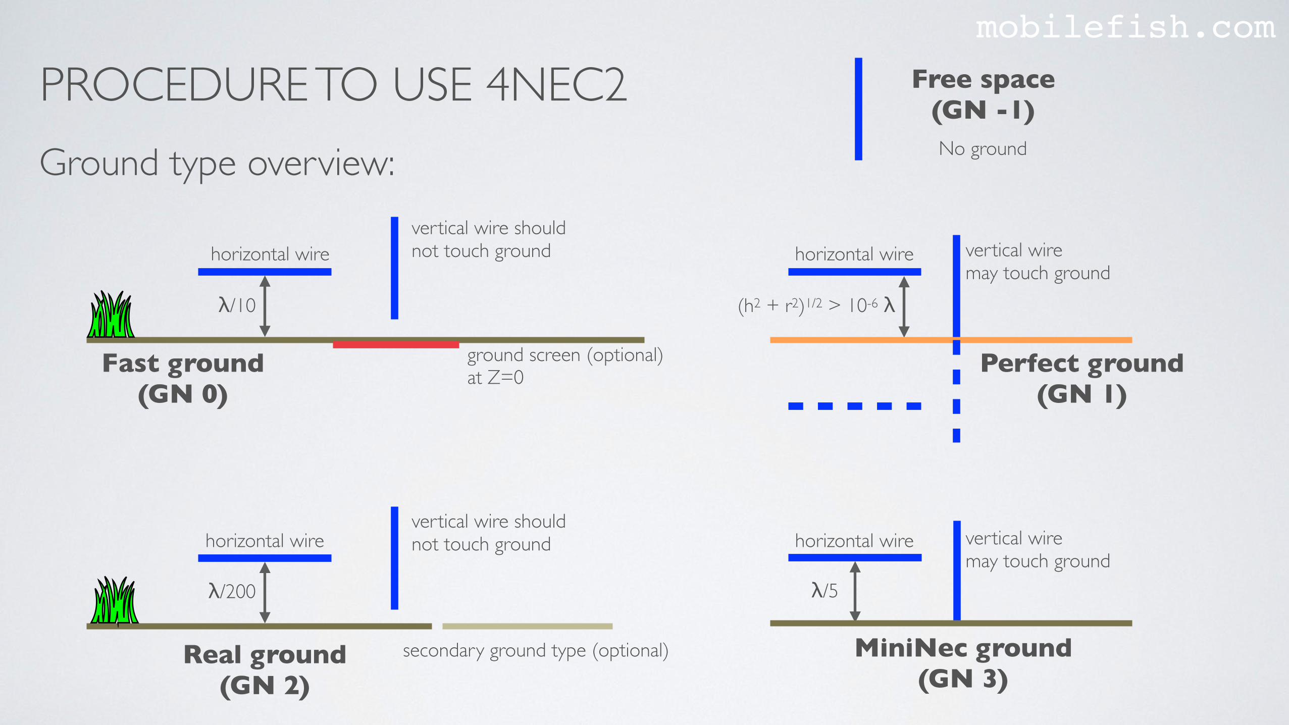
• You can choose between 5 ground types.All ground types extends indefinitely to the horizon.
• Free space (GN -1) There is an absence of any surface beneath the antenna. There is no ground influence. The antenna radiates in all directions without reflections.Use this option to compare antennas of similar types.
• Fast ground (GN 0 0 0 0 3 0.0001) Can model a ground screen (number of radials etc) at Z=0.Vertical and horizontal wires should not touch ground. Horizontal wires should be at least λ/10 above ground.
PROCEDURE TO USE 4NEC2mobilefish.com
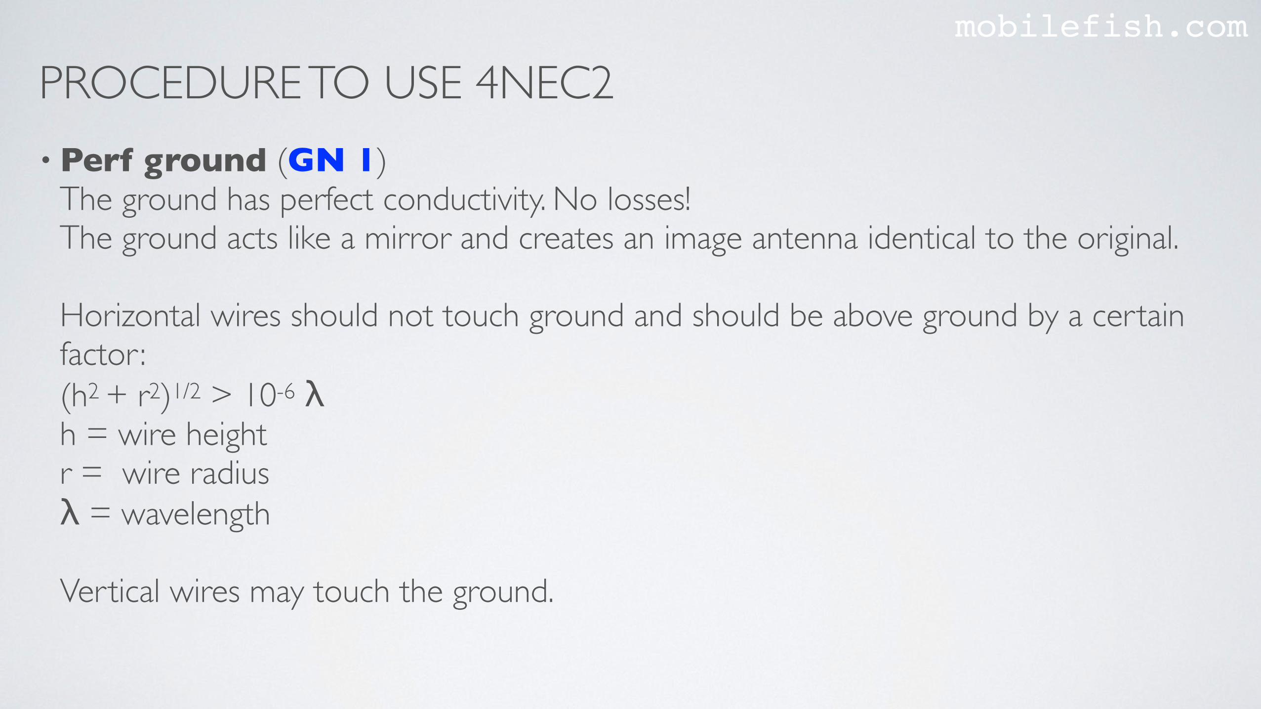
• Perf ground (GN 1) The ground has perfect conductivity. No losses!The ground acts like a mirror and creates an image antenna identical to the original.Horizontal wires should not touch ground and should be above ground by a certain factor : (h2 + r2)1/2 > 10-6 λh = wire heightr = wire radius λ = wavelength Vertical wires may touch the ground.
PROCEDURE TO USE 4NEC2mobilefish.com
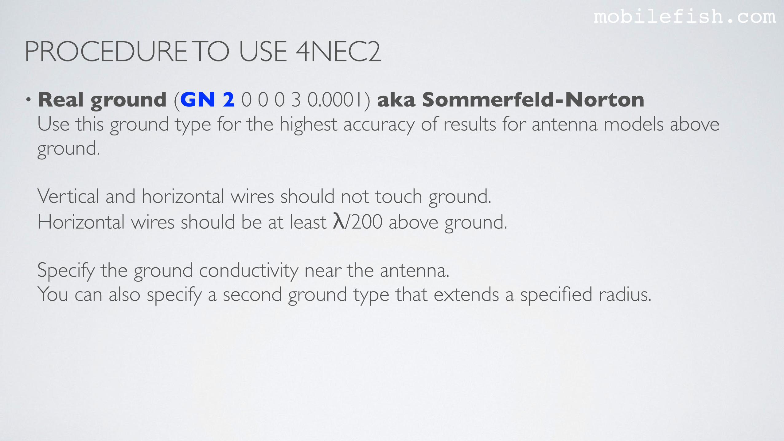
• Real ground (GN 2 0 0 0 3 0.0001) aka Sommerfeld-Norton Use this ground type for the highest accuracy of results for antenna models above ground. Vertical and horizontal wires should not touch ground. Horizontal wires should be at least λ/200 above ground.Specify the ground conductivity near the antenna. You can also specify a second ground type that extends a specified radius.
PROCEDURE TO USE 4NEC2mobilefish.com
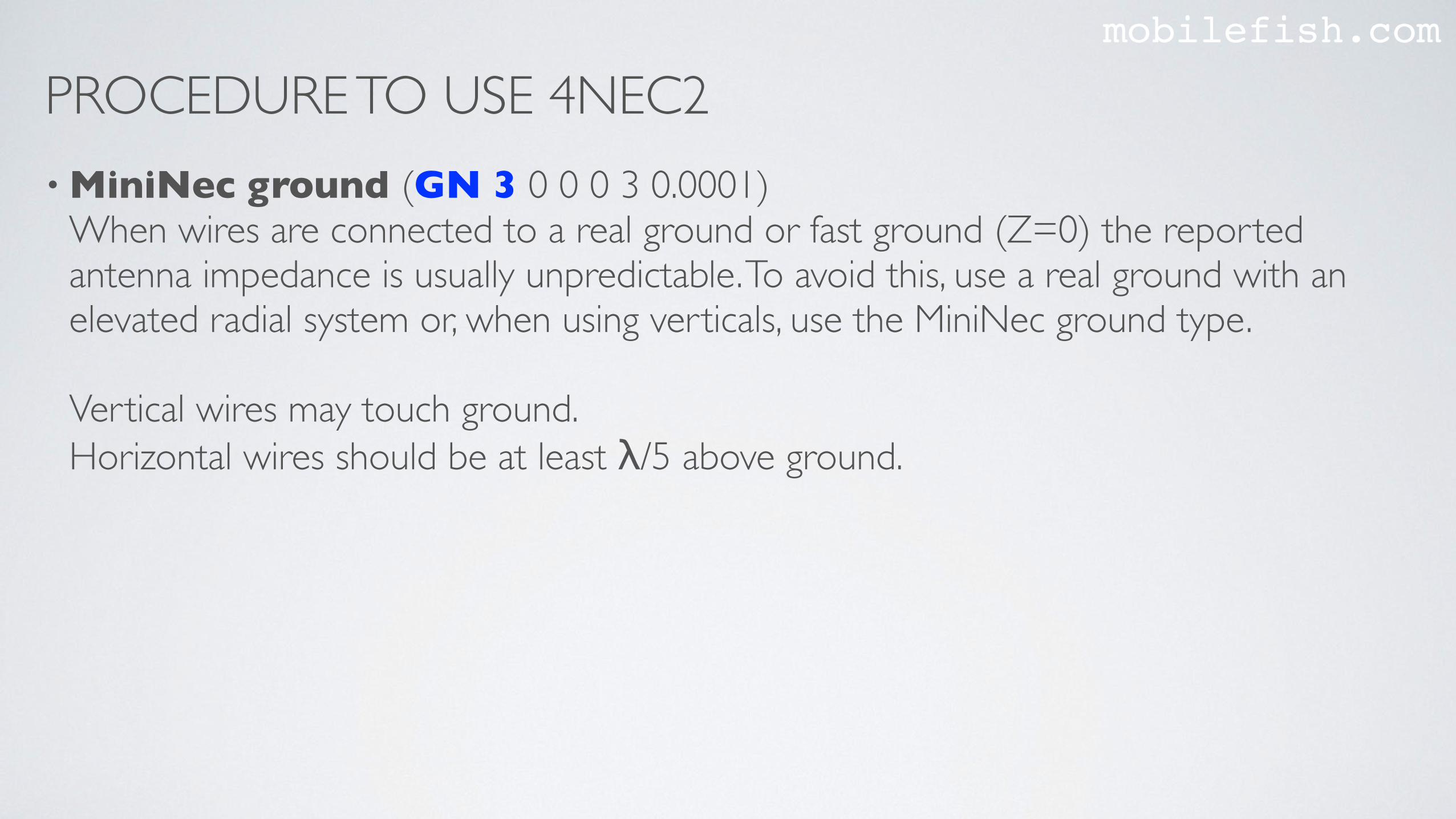
• MiniNec ground (GN 3 0 0 0 3 0.0001) When wires are connected to a real ground or fast ground (Z=0) the reported antenna impedance is usually unpredictable. To avoid this, use a real ground with an elevated radial system or, when using verticals, use the MiniNec ground type.Vertical wires may touch ground. Horizontal wires should be at least λ/5 above ground.
PROCEDURE TO USE 4NEC2mobilefish.com
Ground type overview:
λ/10
ground screen (optional) at Z=0Fast ground
(GN 0)
(h2 + r2)1/2 > 10-6 λ
λ/200
Real ground (GN 2)
MiniNec ground (GN 3)
Perfect ground (GN 1)
vertical wiremay touch ground
λ/5
vertical wiremay touch ground
vertical wire should not touch ground
vertical wire should not touch ground horizontal wirehorizontal wire
horizontal wire horizontal wire
secondary ground type (optional)
No ground
Free space (GN -1)
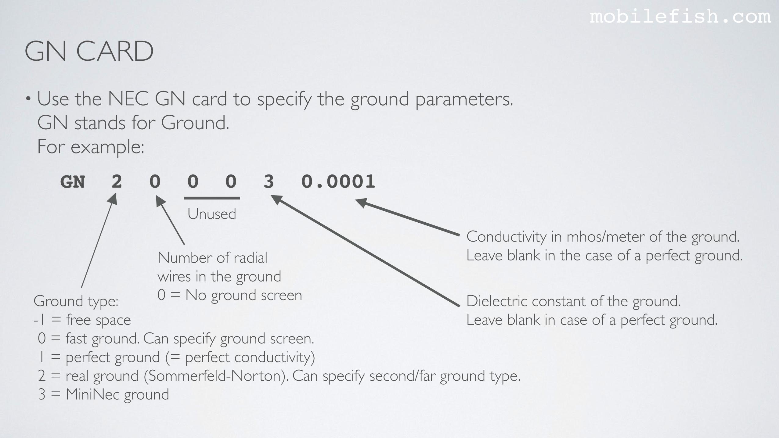
GN CARDmobilefish.com
• Use the NEC GN card to specify the ground parameters.GN stands for Ground.For example:
Unused
Number of radial wires in the ground0 = No ground screenGround type:
-1 = free space 0 = fast ground. Can specify ground screen. 1 = perfect ground (= perfect conductivity) 2 = real ground (Sommerfeld-Norton). Can specify second/far ground type. 3 = MiniNec ground
GN 2 0 0 0 3 0.0001
Dielectric constant of the ground.Leave blank in case of a perfect ground.
Conductivity in mhos/meter of the ground.Leave blank in the case of a perfect ground.

GN CARDmobilefish.com
• Free space: GN -1 Perfect ground: GN 1
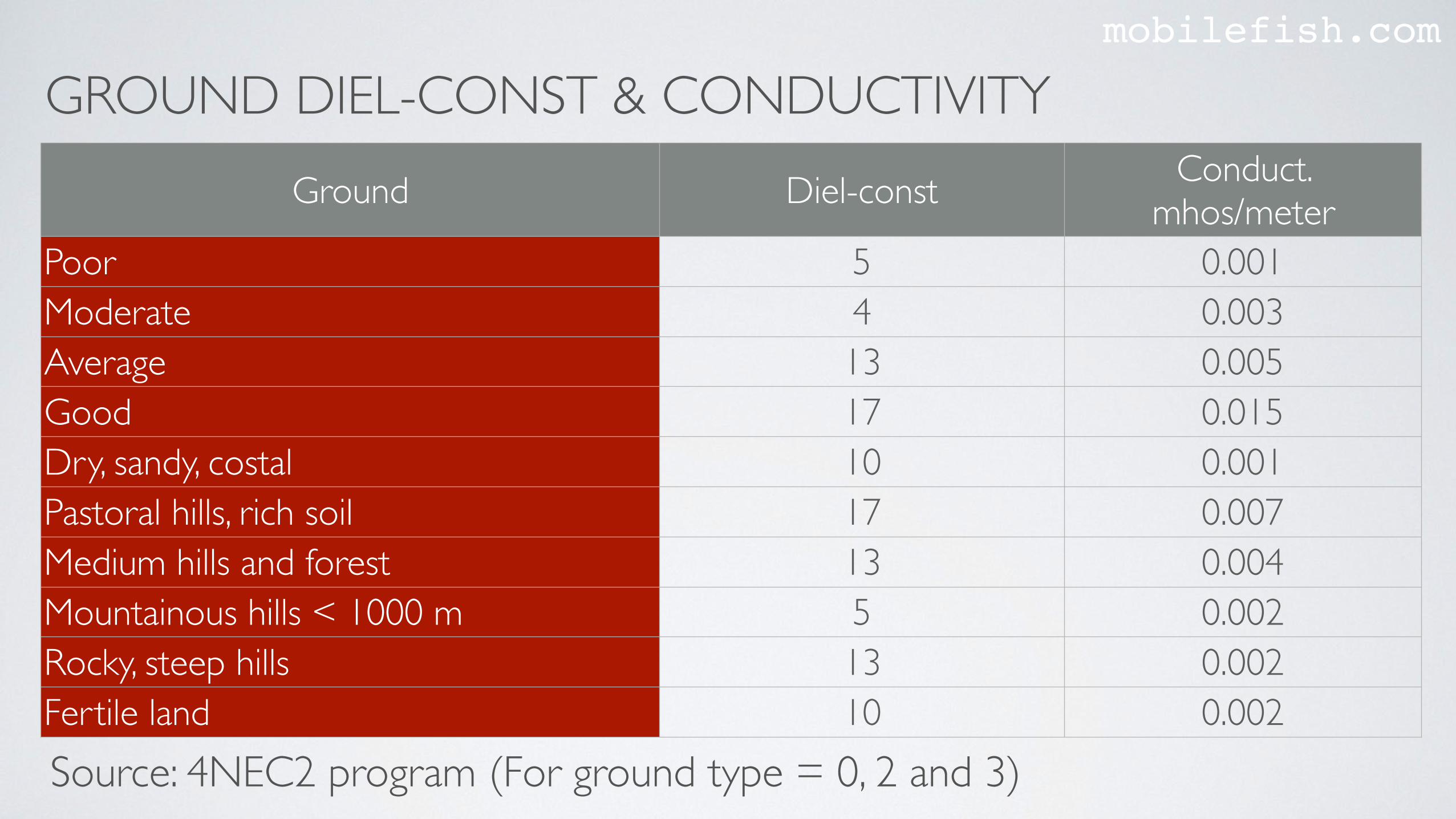
GROUND DIEL-CONST & CONDUCTIVITYmobilefish.com
Ground Diel-const Conduct. mhos/meter
Poor 5 0.001Moderate 4 0.003Average 13 0.005Good 17 0.015Dry, sandy, costal 10 0.001Pastoral hills, rich soil 17 0.007Medium hills and forest 13 0.004Mountainous hills < 1000 m 5 0.002Rocky, steep hills 13 0.002Fertile land 10 0.002Source: 4NEC2 program (For ground type = 0, 2 and 3)
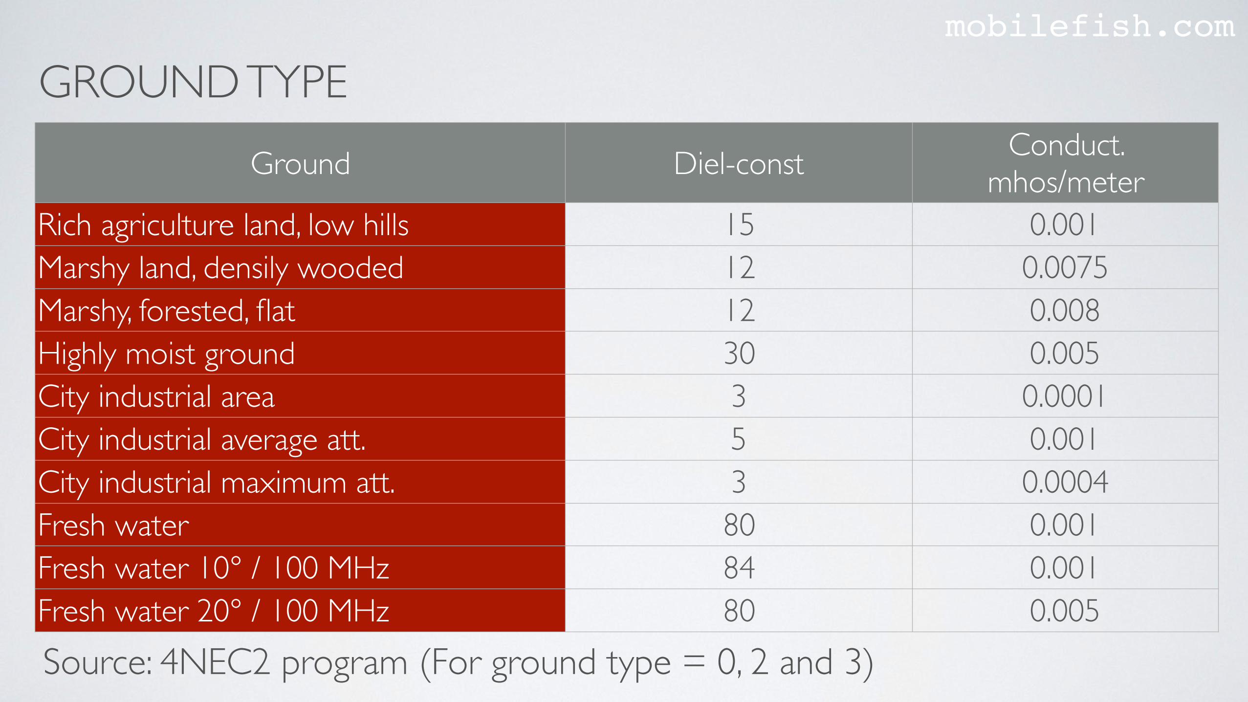
GROUND TYPEmobilefish.com
Ground Diel-const Conduct. mhos/meter
Rich agriculture land, low hills 15 0.001Marshy land, densily wooded 12 0.0075Marshy, forested, flat 12 0.008Highly moist ground 30 0.005City industrial area 3 0.0001City industrial average att. 5 0.001City industrial maximum att. 3 0.0004Fresh water 80 0.001Fresh water 10° / 100 MHz 84 0.001Fresh water 20° / 100 MHz 80 0.005Source: 4NEC2 program (For ground type = 0, 2 and 3)
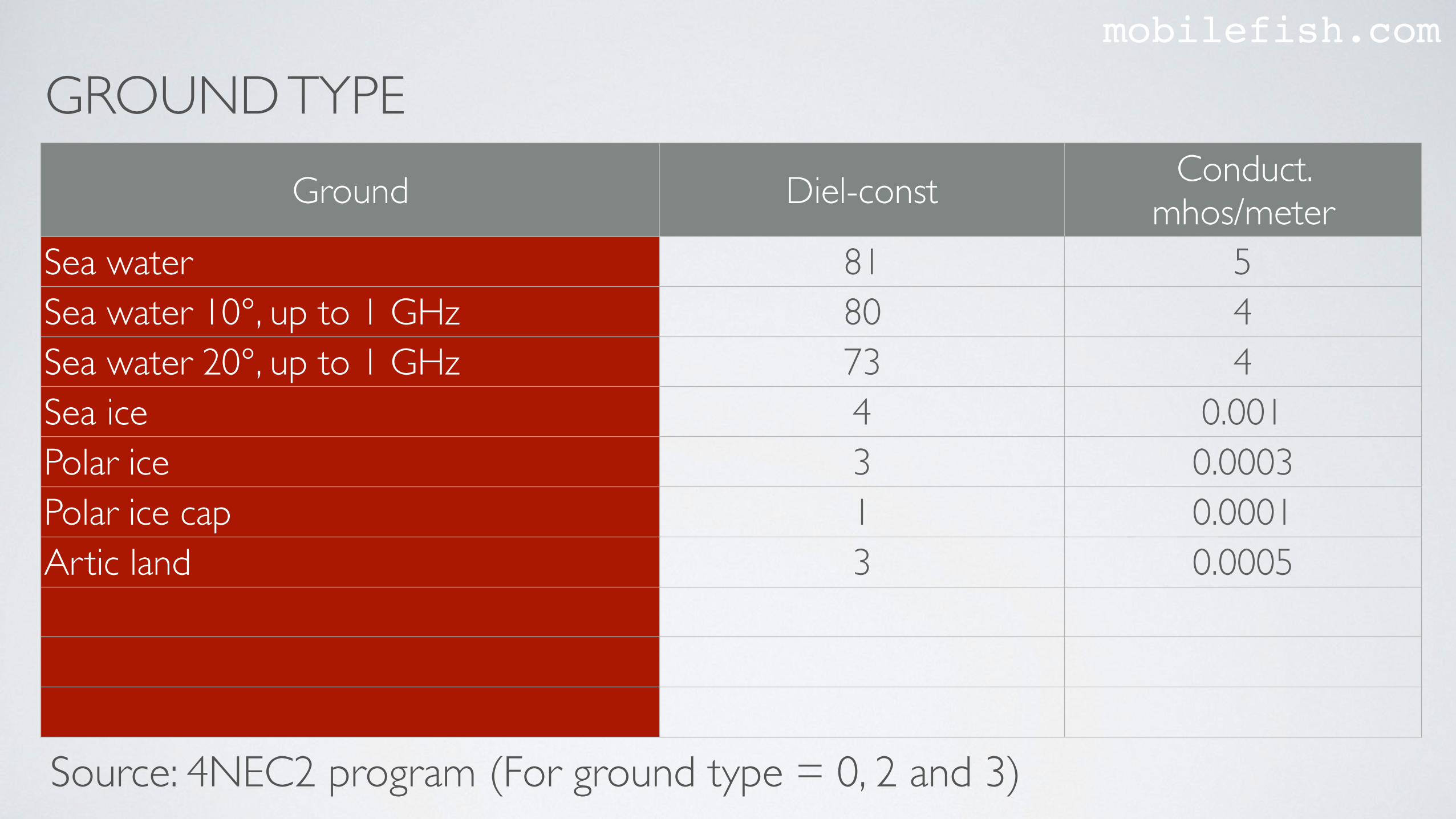
GROUND TYPEmobilefish.com
Ground Diel-const Conduct. mhos/meter
Sea water 81 5Sea water 10°, up to 1 GHz 80 4Sea water 20°, up to 1 GHz 73 4Sea ice 4 0.001Polar ice 3 0.0003Polar ice cap 1 0.0001Artic land 3 0.0005
Source: 4NEC2 program (For ground type = 0, 2 and 3)
PROCEDURE TO USE 4NEC2mobilefish.com
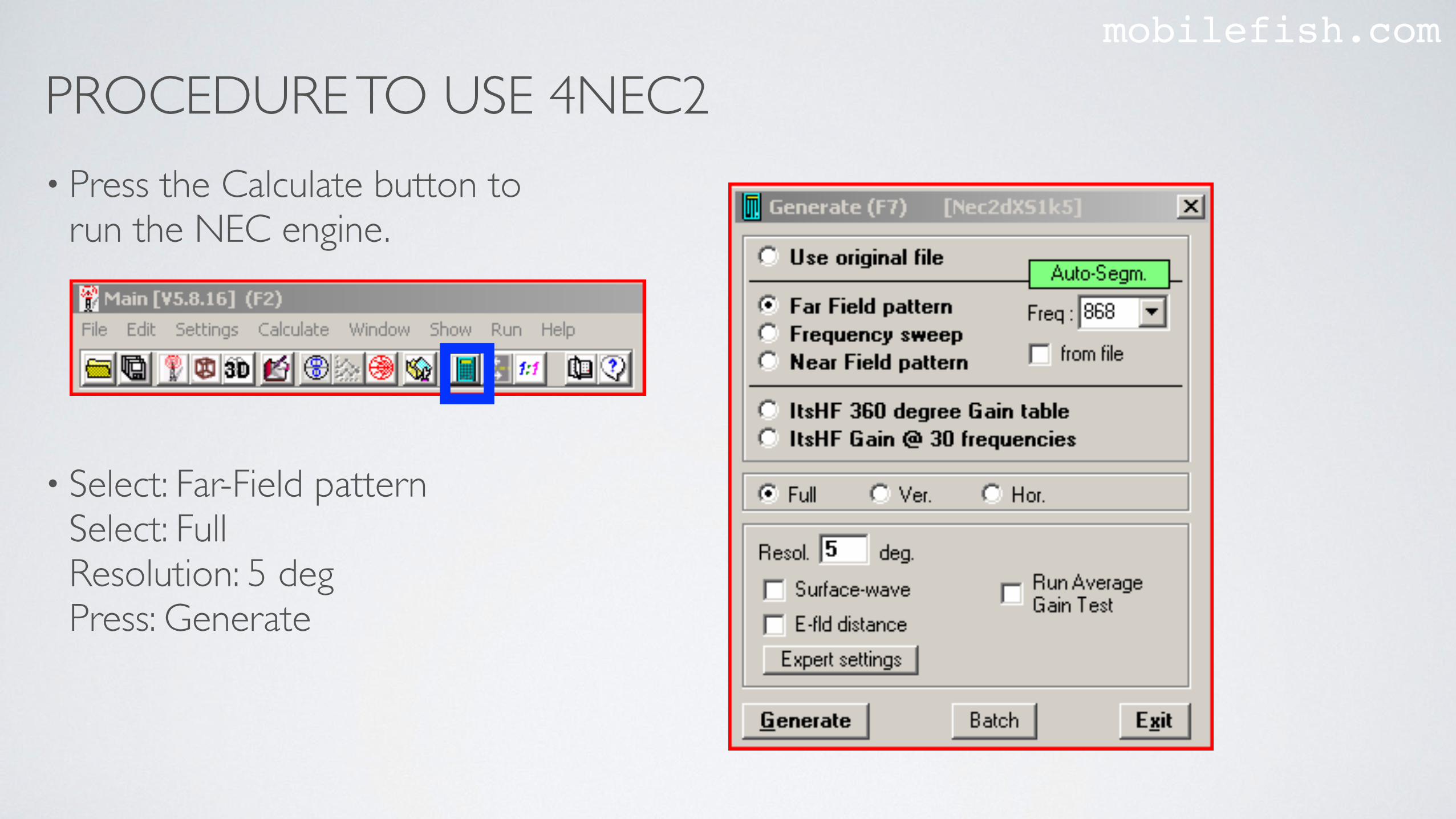
• Press the Calculate button to run the NEC engine.
• Select: Far-Field pattern Select: FullResolution: 5 degPress: Generate

PROCEDURE TO USE 4NEC2mobilefish.com
• In the Main window, you can see the calculated SWR.
PROCEDURE TO USE 4NEC2mobilefish.com
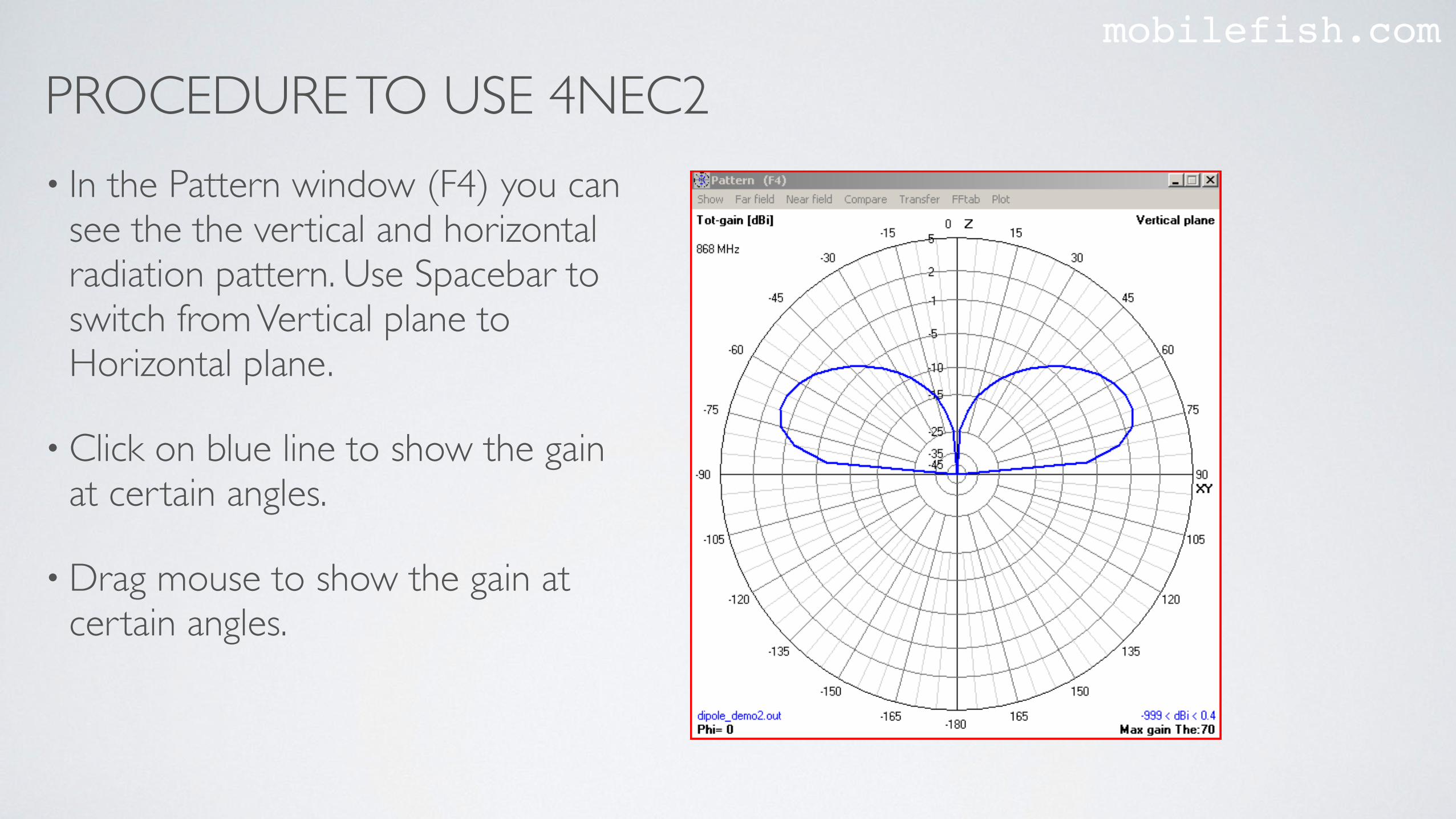
• In the Pattern window (F4) you can see the the vertical and horizontal radiation pattern. Use Spacebar to switch from Vertical plane to Horizontal plane.
• Click on blue line to show the gain at certain angles.
• Drag mouse to show the gain at certain angles.
AZIMUTH & ELEVATIONmobilefish.com
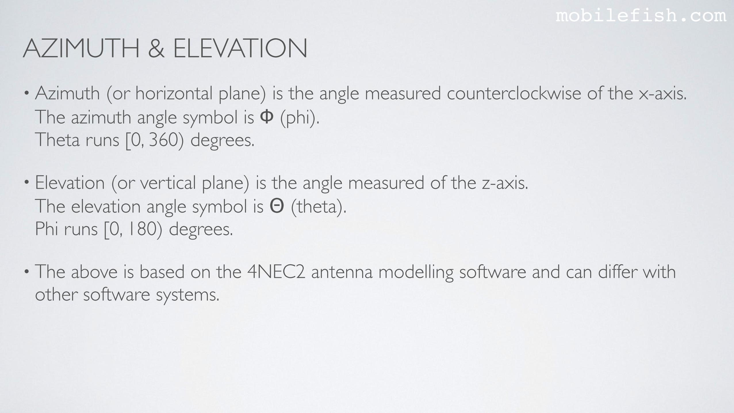
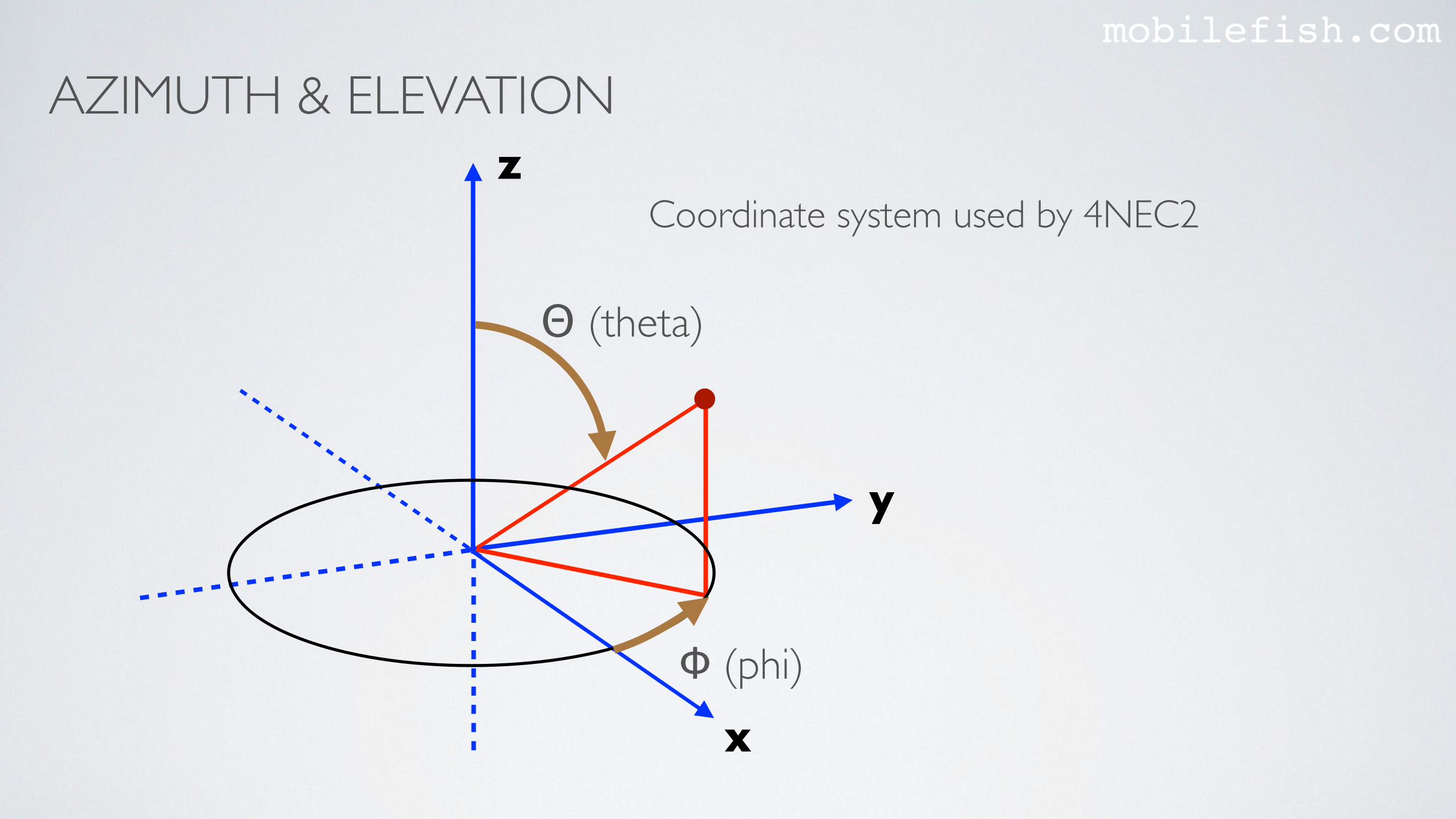
• Azimuth (or horizontal plane) is the angle measured counterclockwise of the x-axis. The azimuth angle symbol is Φ (phi).Theta runs [0, 360) degrees.
• Elevation (or vertical plane) is the angle measured of the z-axis. The elevation angle symbol is Θ (theta).Phi runs [0, 180) degrees.
• The above is based on the 4NEC2 antenna modelling software and can differ with other software systems.
AZIMUTH & ELEVATIONmobilefish.com
y
x
z
Φ (phi)
Θ (theta)
Coordinate system used by 4NEC2
AZIMUTH & ELEVATIONmobilefish.com
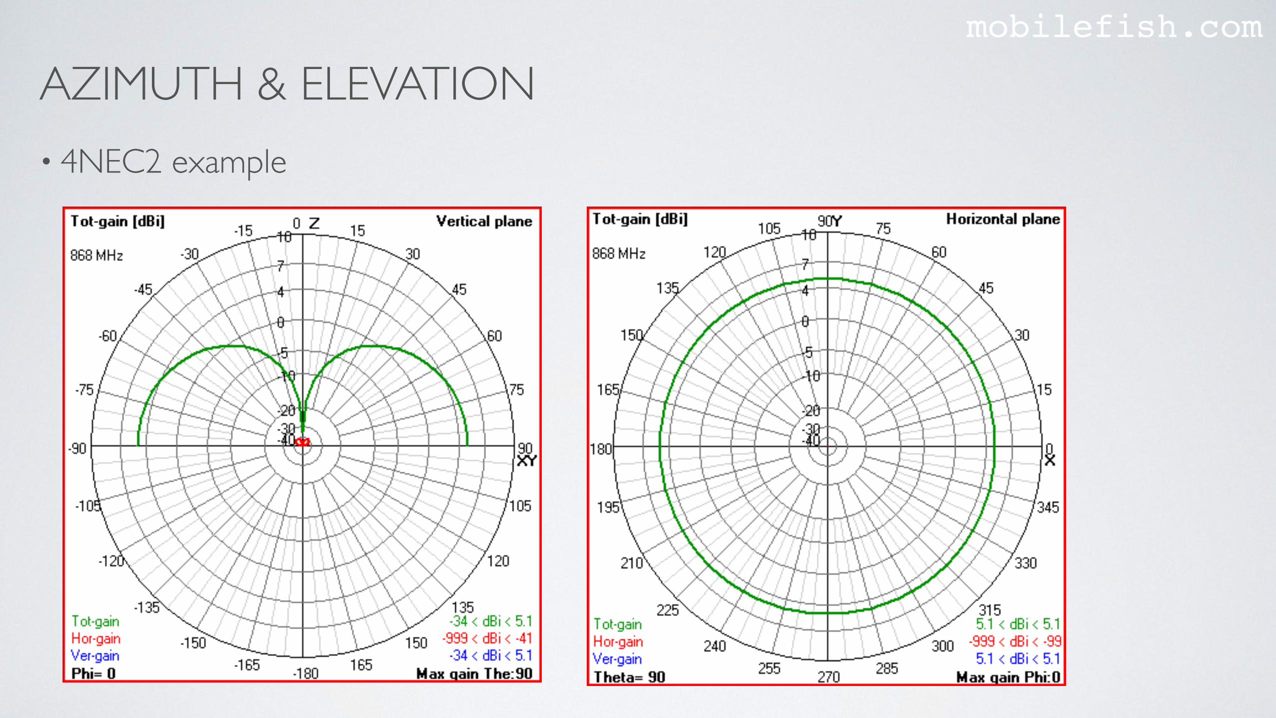
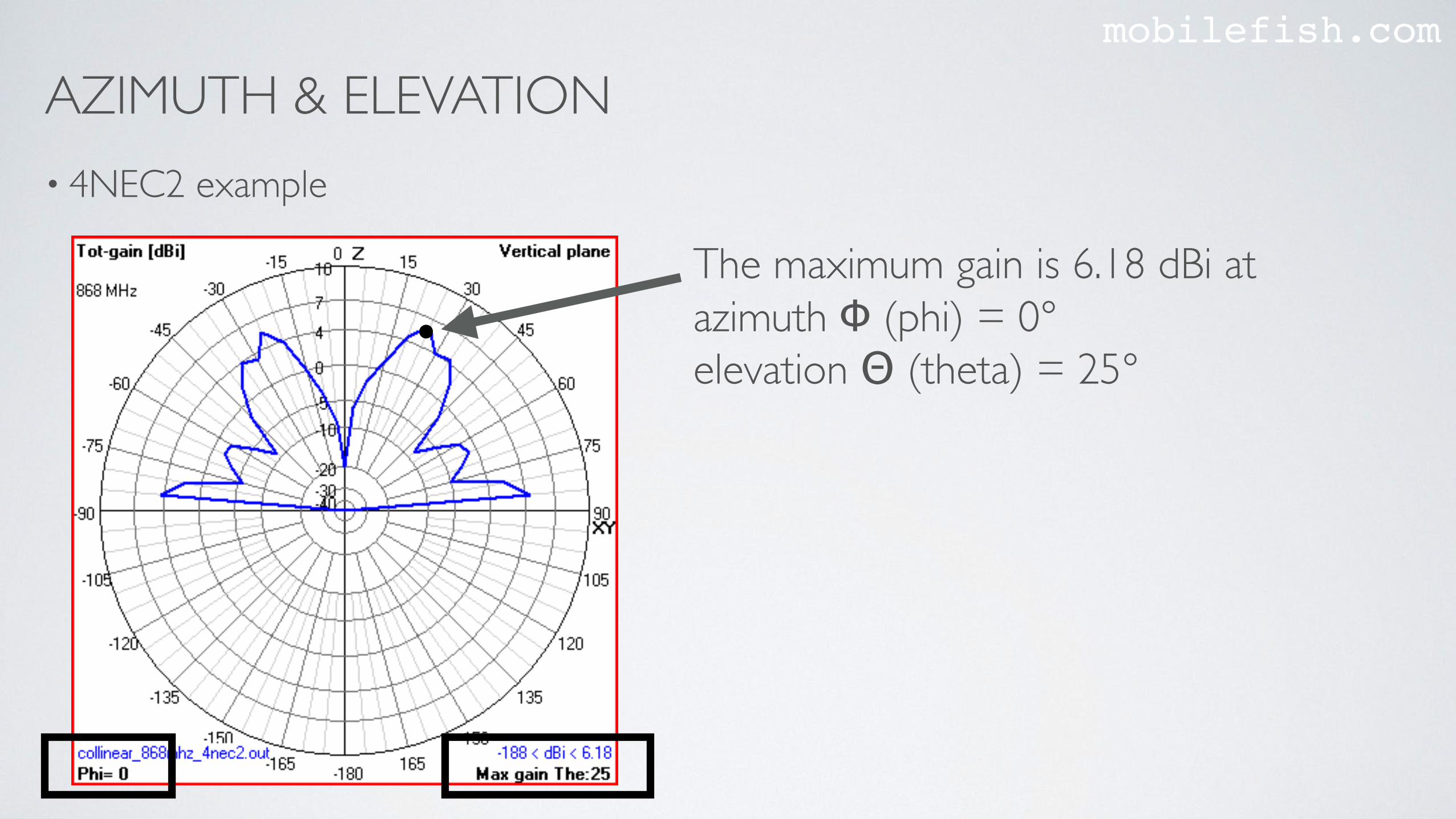
• 4NEC2 example
AZIMUTH & ELEVATIONmobilefish.com
• 4NEC2 example
The maximum gain is 6.18 dBi atazimuth Φ (phi) = 0°elevation Θ (theta) = 25°
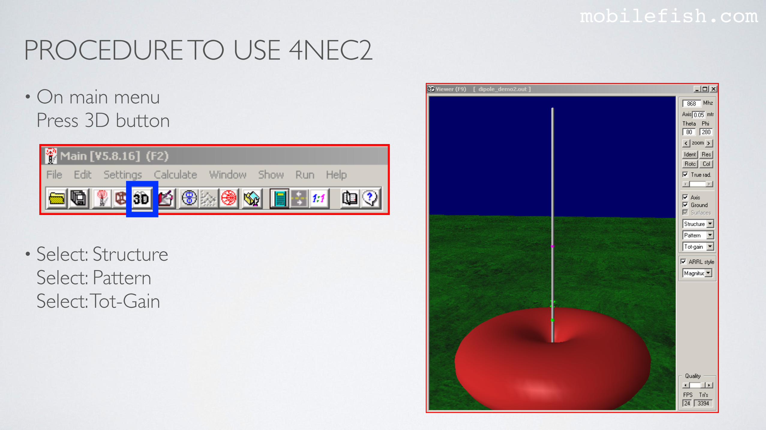
PROCEDURE TO USE 4NEC2mobilefish.com
• On main menu Press 3D button
• Select: Structure Select: Pattern Select: Tot-Gain
PROCEDURE TO USE 4NEC2mobilefish.com
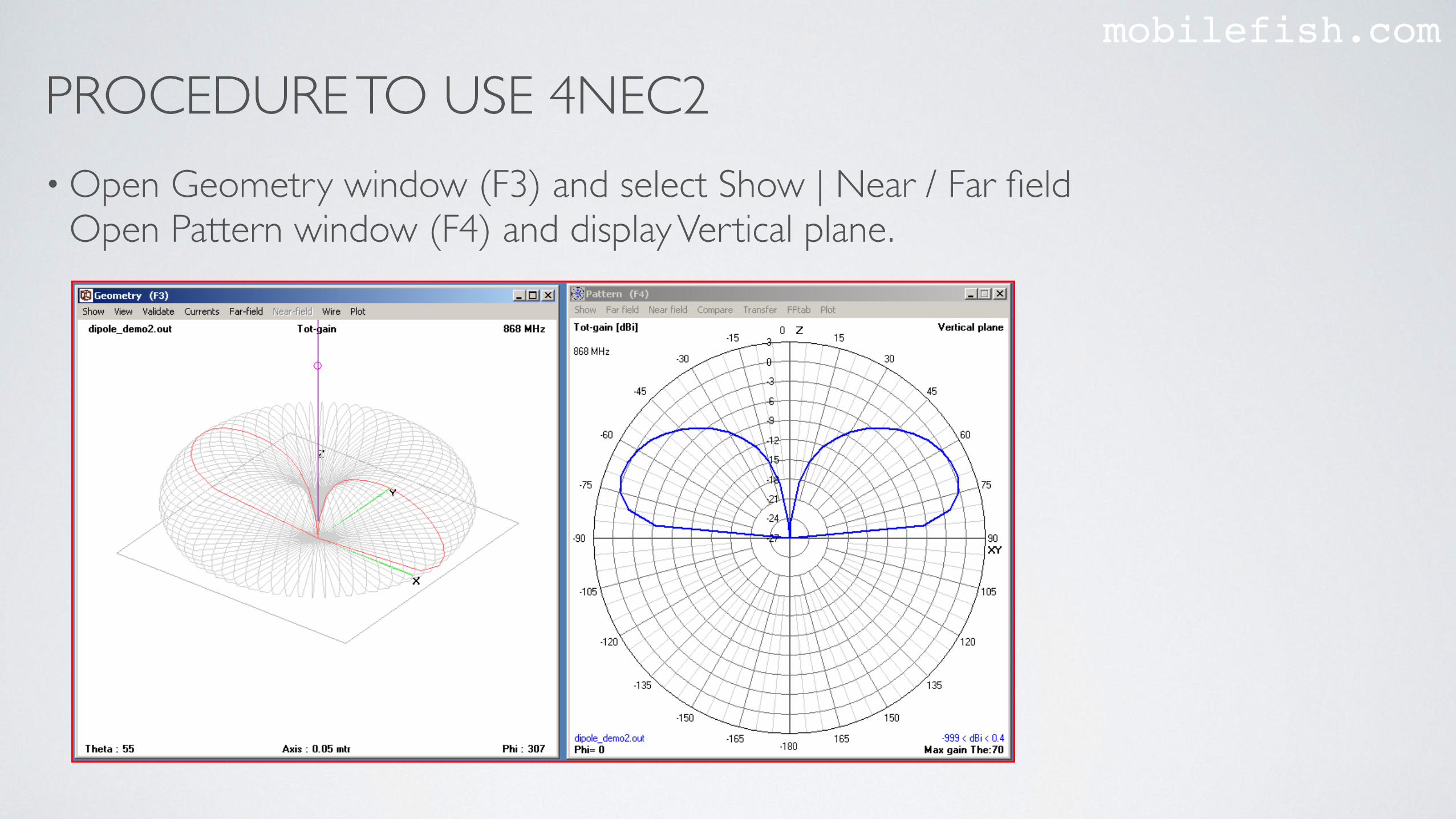
• Open Geometry window (F3) and select Show | Near / Far fieldOpen Pattern window (F4) and display Vertical plane.
PROCEDURE TO USE 4NEC2mobilefish.com
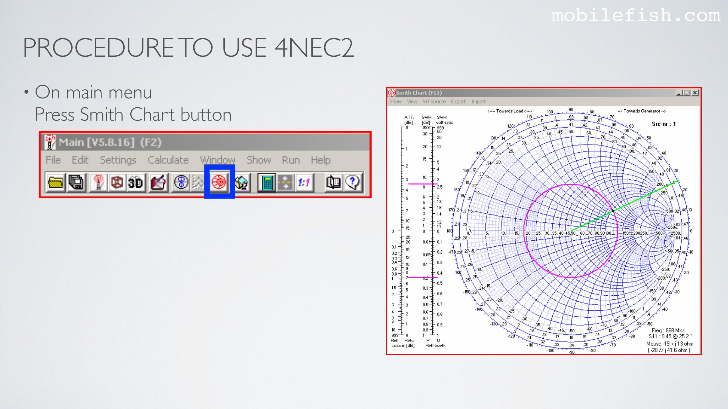
• On main menu Press Smith Chart button
PROCEDURE TO USE 4NEC2mobilefish.com
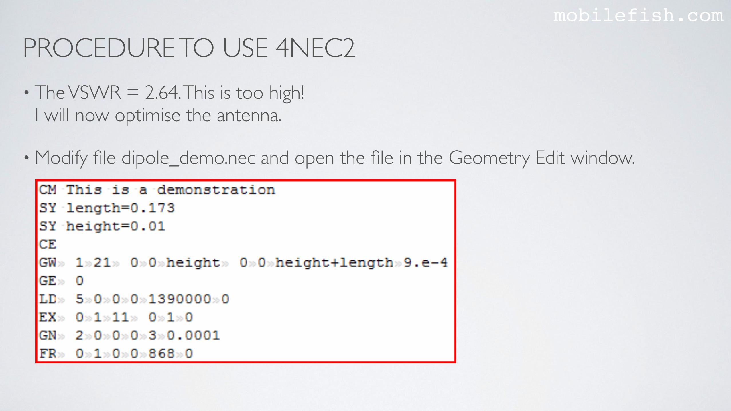
• The VSWR = 2.64. This is too high!I will now optimise the antenna.
• Modify file dipole_demo.nec and open the file in the Geometry Edit window.
PROCEDURE TO USE 4NEC2mobilefish.com
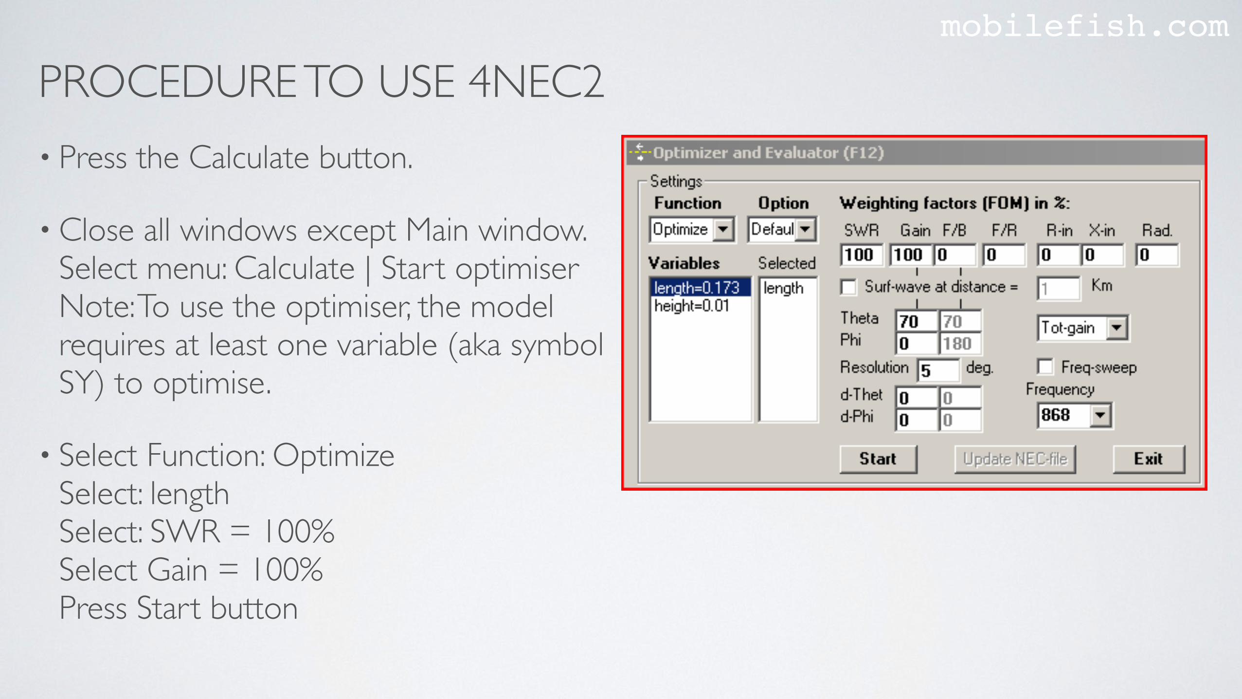
• Press the Calculate button.
• Close all windows except Main window.Select menu: Calculate | Start optimiserNote: To use the optimiser, the model requires at least one variable (aka symbol SY) to optimise.
• Select Function: OptimizeSelect: length Select: SWR = 100% Select Gain = 100% Press Start button
PROCEDURE TO USE 4NEC2mobilefish.com
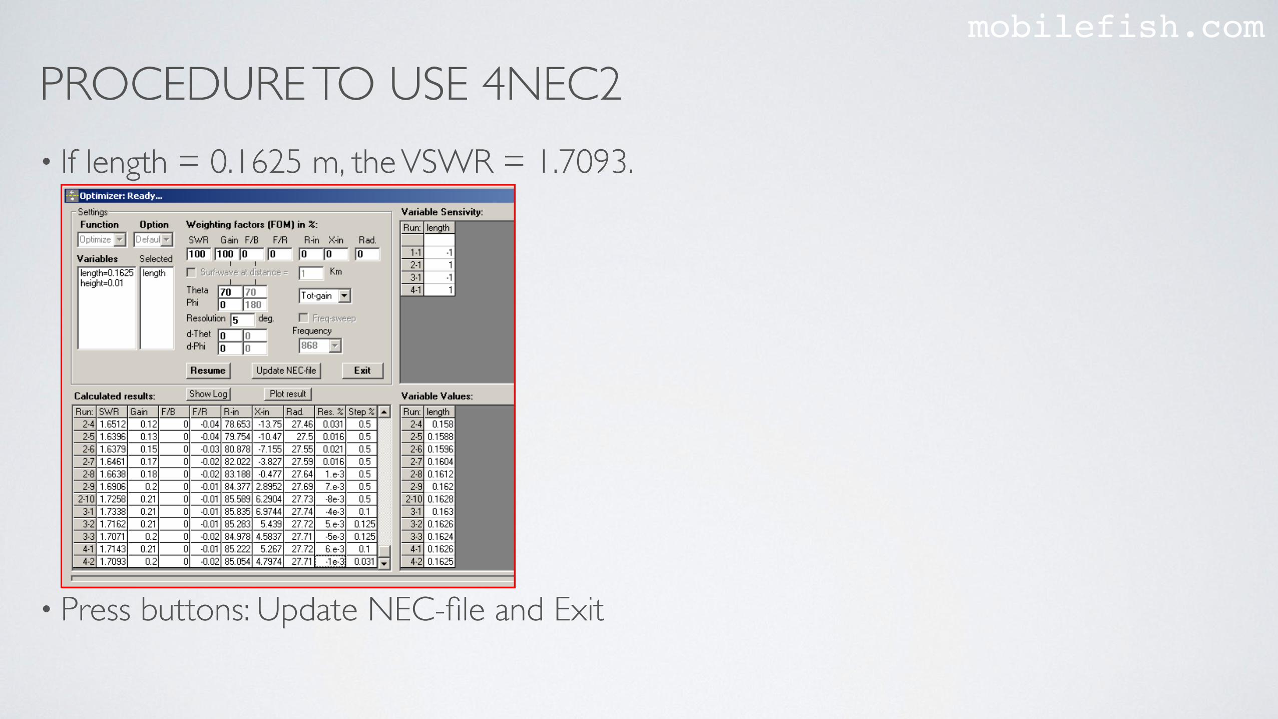
• If length = 0.1625 m, the VSWR = 1.7093.
• Press buttons: Update NEC-file and Exit
PROCEDURE TO USE 4NEC2mobilefish.com
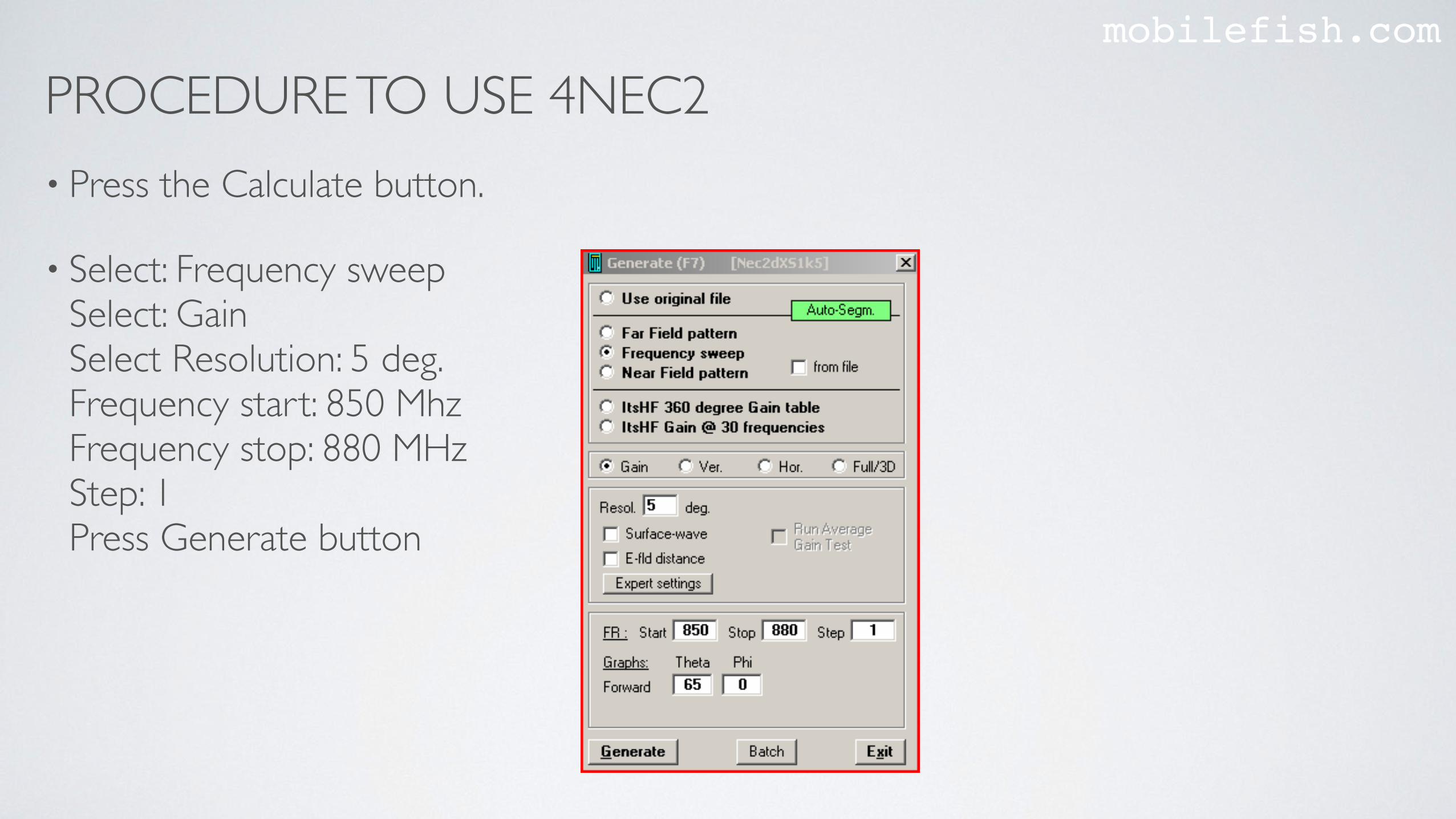
• Press the Calculate button.
• Select: Frequency sweepSelect: Gain Select Resolution: 5 deg.Frequency start: 850 MhzFrequency stop: 880 MHz Step: 1Press Generate button
PROCEDURE TO USE 4NEC2mobilefish.com
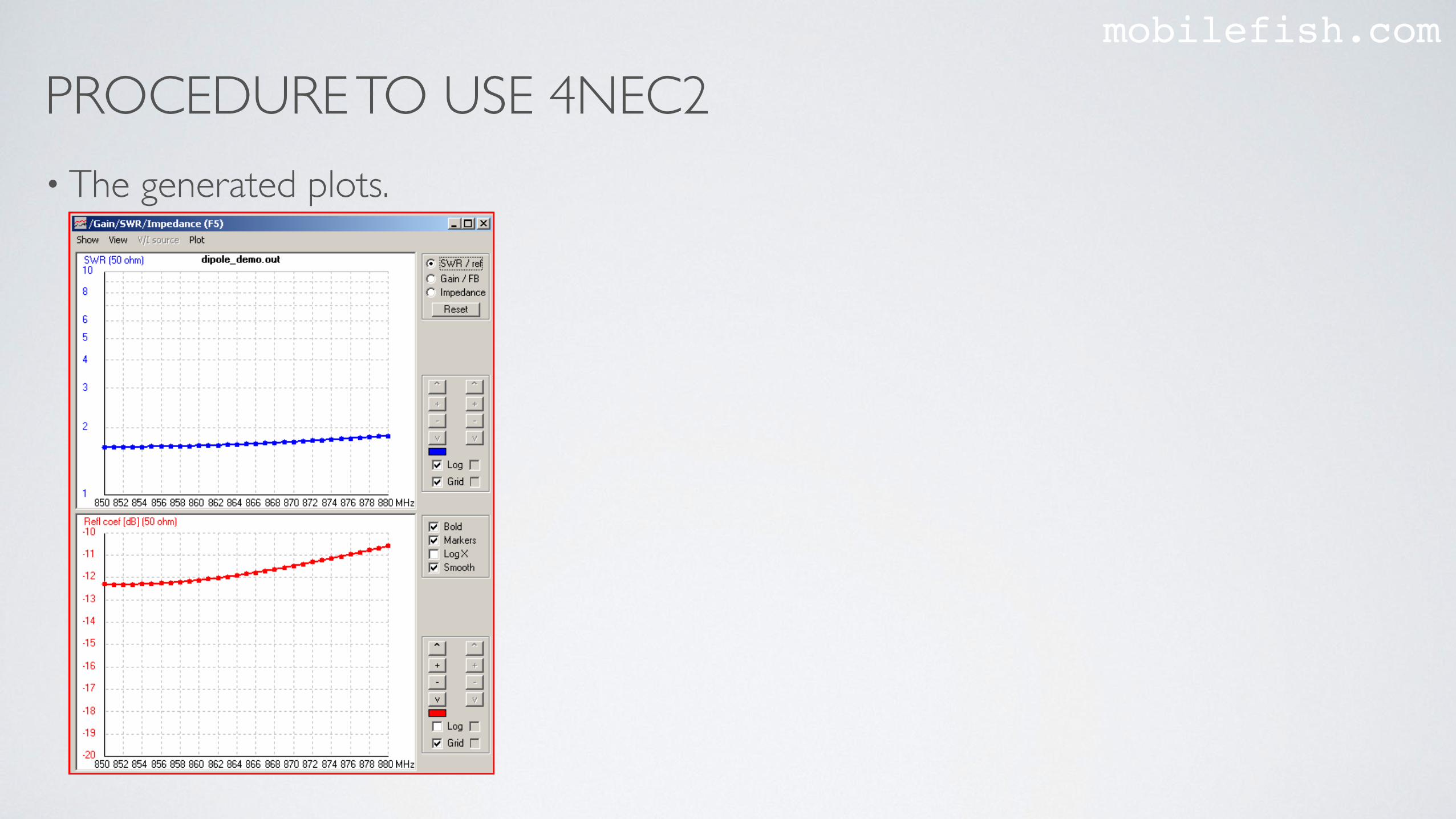
• The generated plots.
PROCEDURE TO USE 4NEC2mobilefish.com
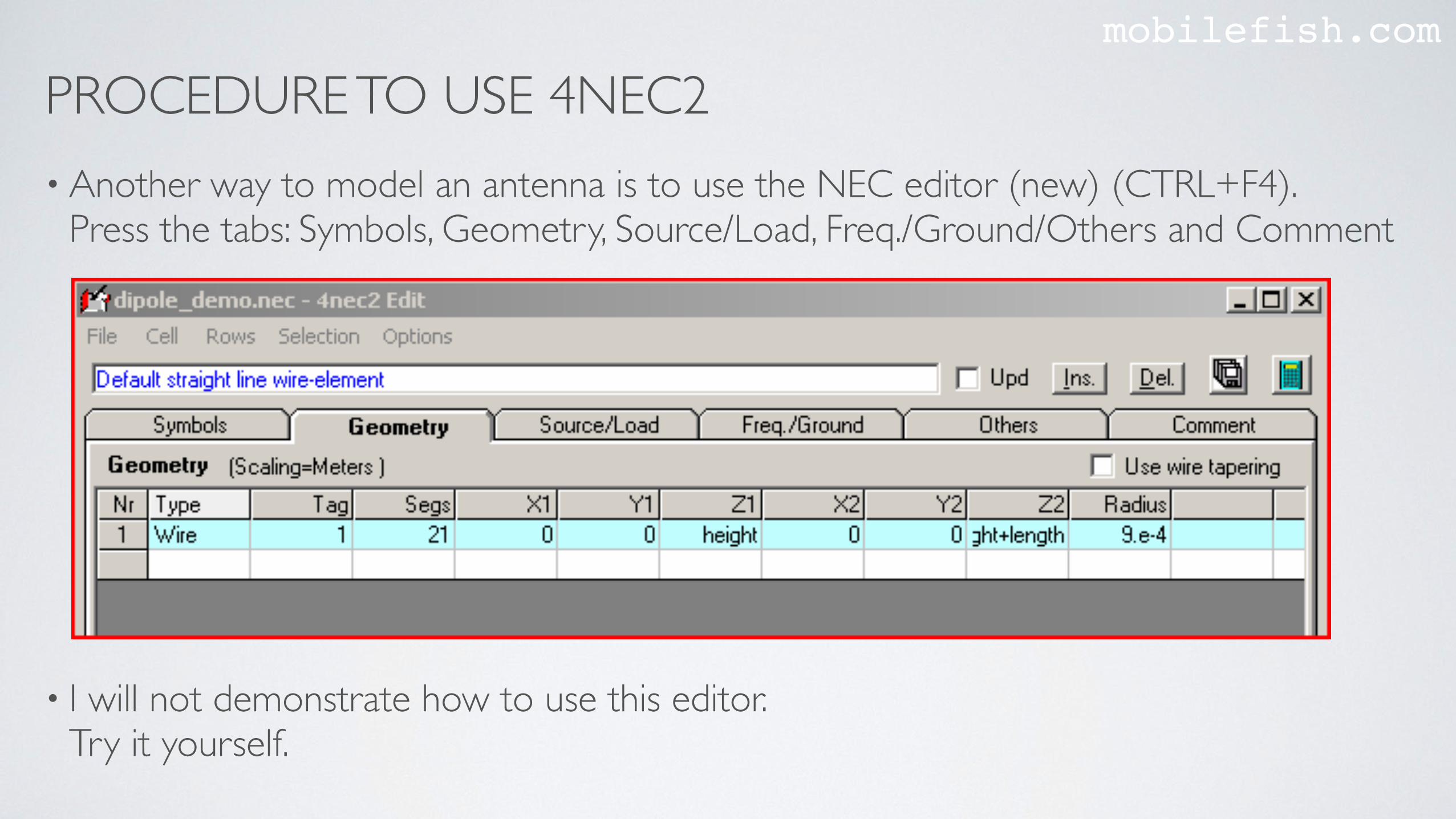
• Another way to model an antenna is to use the NEC editor (new) (CTRL+F4). Press the tabs: Symbols, Geometry, Source/Load, Freq./Ground/Others and Comment
• I will not demonstrate how to use this editor.Try it yourself.
PROCEDURE TO USE 4NEC2mobilefish.com
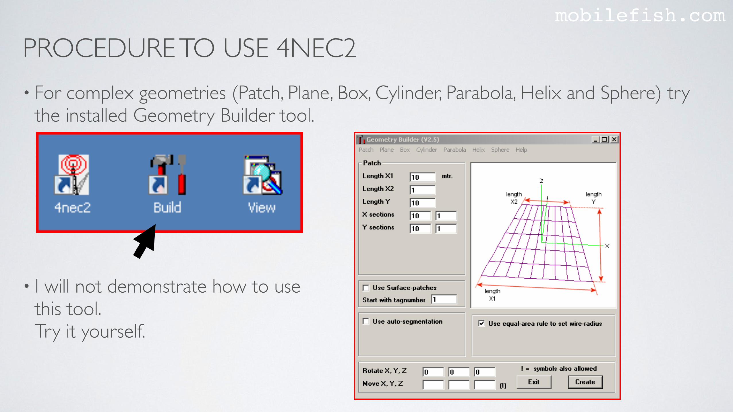
• For complex geometries (Patch, Plane, Box, Cylinder, Parabola, Helix and Sphere) try the installed Geometry Builder tool.
• I will not demonstrate how to use this tool.Try it yourself.
4NEC2 REMARKSmobilefish.com
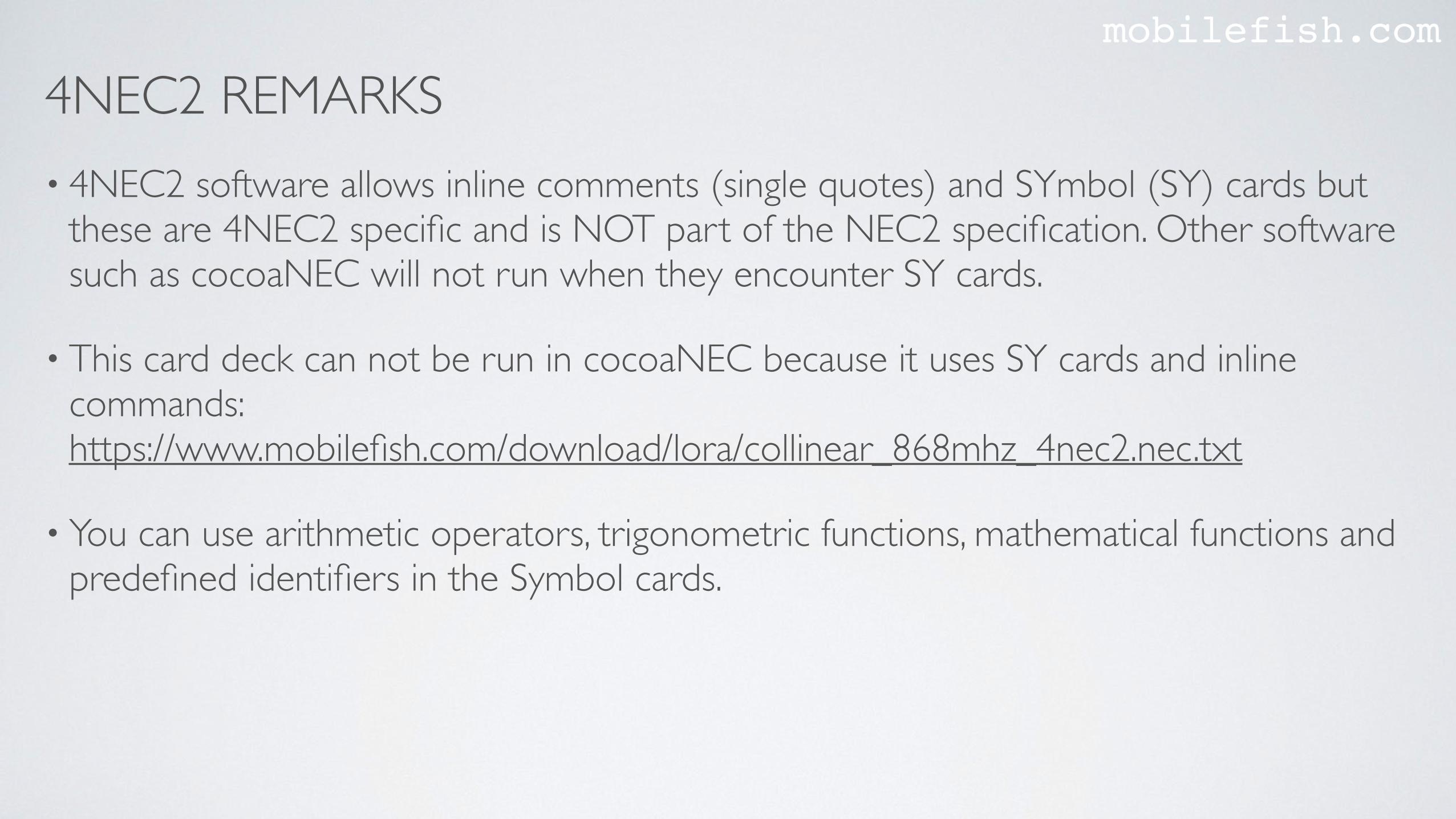
• 4NEC2 software allows inline comments (single quotes) and SYmbol (SY) cards but these are 4NEC2 specific and is NOT part of the NEC2 specification. Other software such as cocoaNEC will not run when they encounter SY cards.
• This card deck can not be run in cocoaNEC because it uses SY cards and inline commands:https://www.mobilefish.com/download/lora/collinear_868mhz_4nec2.nec.txt
• You can use arithmetic operators, trigonometric functions, mathematical functions and predefined identifiers in the Symbol cards.
4NEC2 REMARKSmobilefish.com
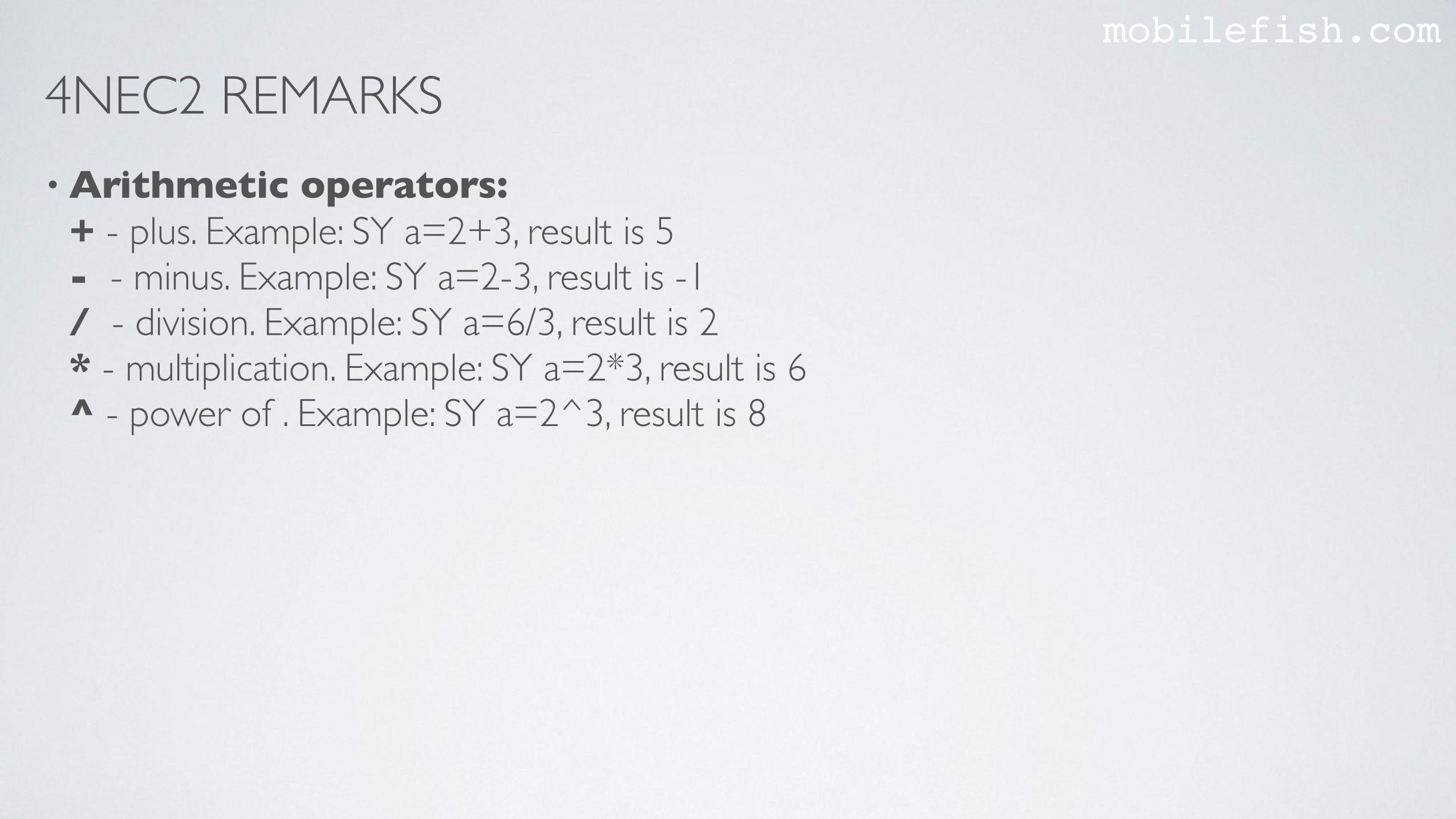
• Arithmetic operators:+ - plus. Example: SY a=2+3, result is 5 - - minus. Example: SY a=2-3, result is -1 / - division. Example: SY a=6/3, result is 2* - multiplication. Example: SY a=2*3, result is 6^ - power of . Example: SY a=2^3, result is 8
4NEC2 REMARKSmobilefish.com
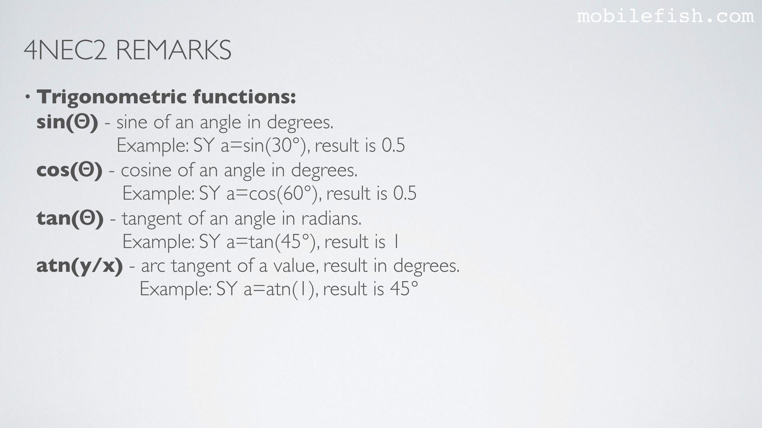
• Trigonometric functions:sin(Θ) - sine of an angle in degrees. Example: SY a=sin(30°), result is 0.5 cos(Θ) - cosine of an angle in degrees. Example: SY a=cos(60°), result is 0.5 tan(Θ) - tangent of an angle in radians. Example: SY a=tan(45°), result is 1 atn(y/x) - arc tangent of a value, result in degrees. Example: SY a=atn(1), result is 45°
4NEC2 REMARKSmobilefish.com
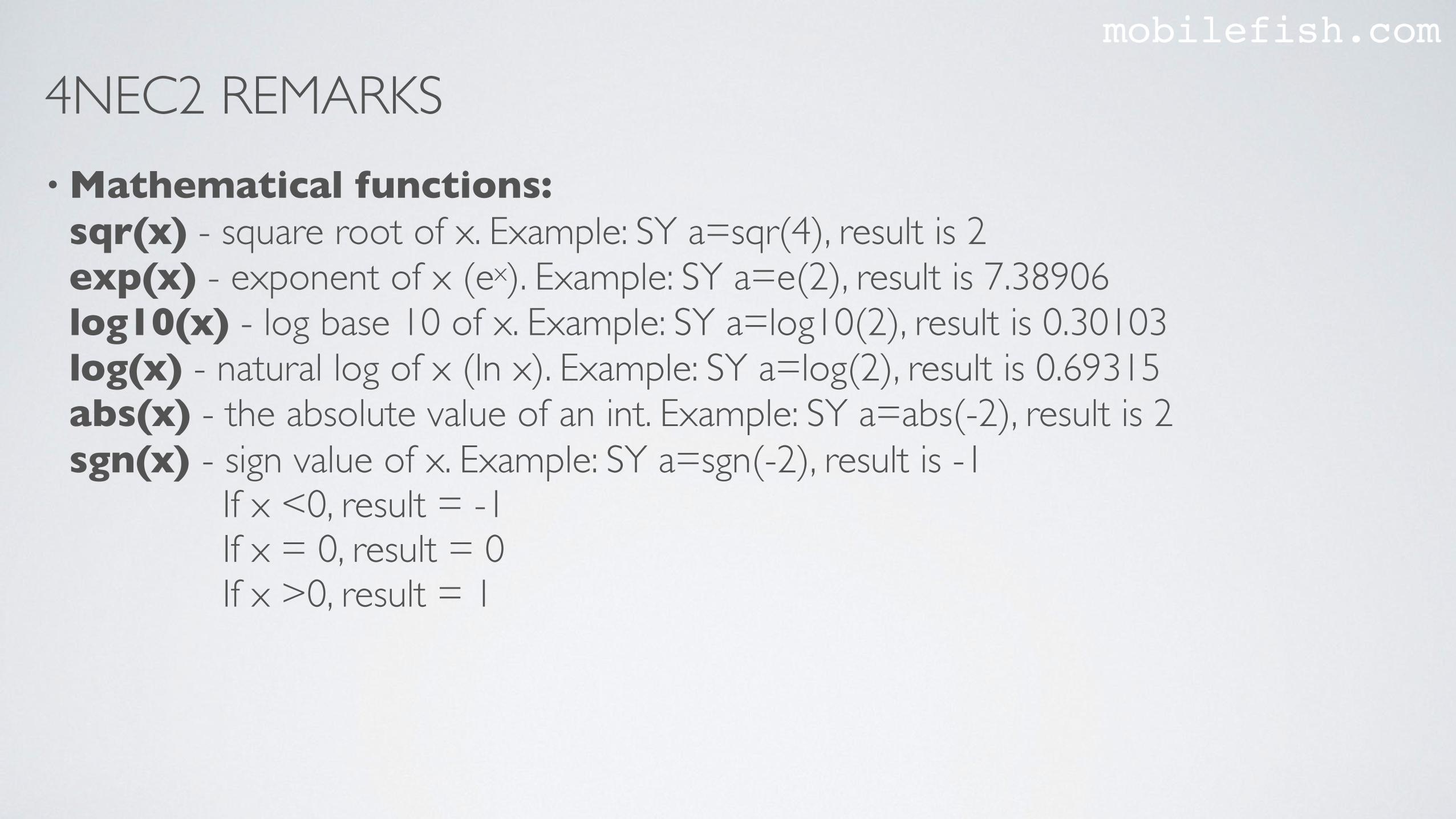
• Mathematical functions:sqr(x) - square root of x. Example: SY a=sqr(4), result is 2 exp(x) - exponent of x (ex). Example: SY a=e(2), result is 7.38906 log10(x) - log base 10 of x. Example: SY a=log10(2), result is 0.30103 log(x) - natural log of x (ln x). Example: SY a=log(2), result is 0.69315 abs(x) - the absolute value of an int. Example: SY a=abs(-2), result is 2 sgn(x) - sign value of x. Example: SY a=sgn(-2), result is -1 If x <0, result = -1 If x = 0, result = 0 If x >0, result = 1
4NEC2 REMARKSmobilefish.com
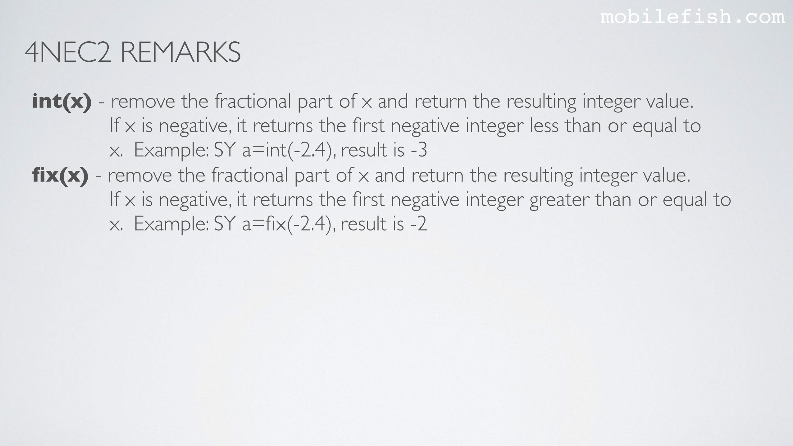
int(x) - remove the fractional part of x and return the resulting integer value. If x is negative, it returns the first negative integer less than or equal to x. Example: SY a=int(-2.4), result is -3 fix(x) - remove the fractional part of x and return the resulting integer value. If x is negative, it returns the first negative integer greater than or equal to x. Example: SY a=fix(-2.4), result is -2
4NEC2 REMARKSmobilefish.com
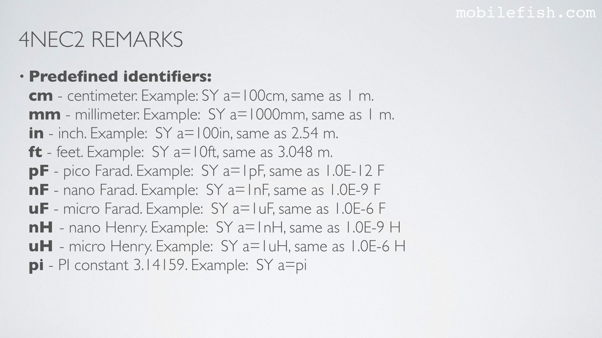
• Predefined identifiers:cm - centimeter. Example: SY a=100cm, same as 1 m.mm - millimeter. Example: SY a=1000mm, same as 1 m.in - inch. Example: SY a=100in, same as 2.54 m.ft - feet. Example: SY a=10ft, same as 3.048 m.pF - pico Farad. Example: SY a=1pF, same as 1.0E-12 FnF - nano Farad. Example: SY a=1nF, same as 1.0E-9 F uF - micro Farad. Example: SY a=1uF, same as 1.0E-6 FnH - nano Henry. Example: SY a=1nH, same as 1.0E-9 H uH - micro Henry. Example: SY a=1uH, same as 1.0E-6 H pi - PI constant 3.14159. Example: SY a=pi
4NEC2 REMARKSmobilefish.com
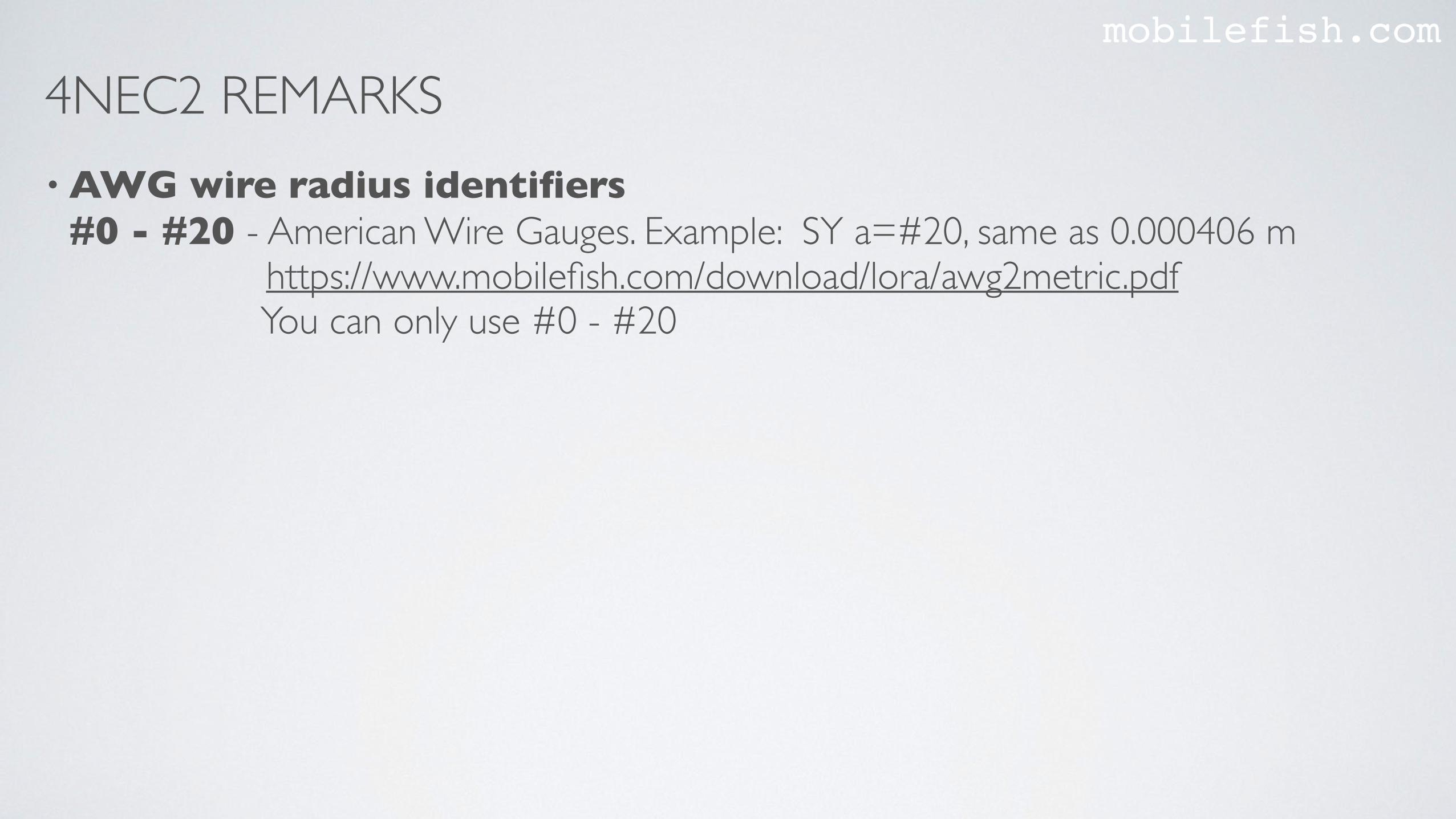
• AWG wire radius identifiers#0 - #20 - American Wire Gauges. Example: SY a=#20, same as 0.000406 m https://www.mobilefish.com/download/lora/awg2metric.pdf You can only use #0 - #20
4NEC2 REMARKSmobilefish.com
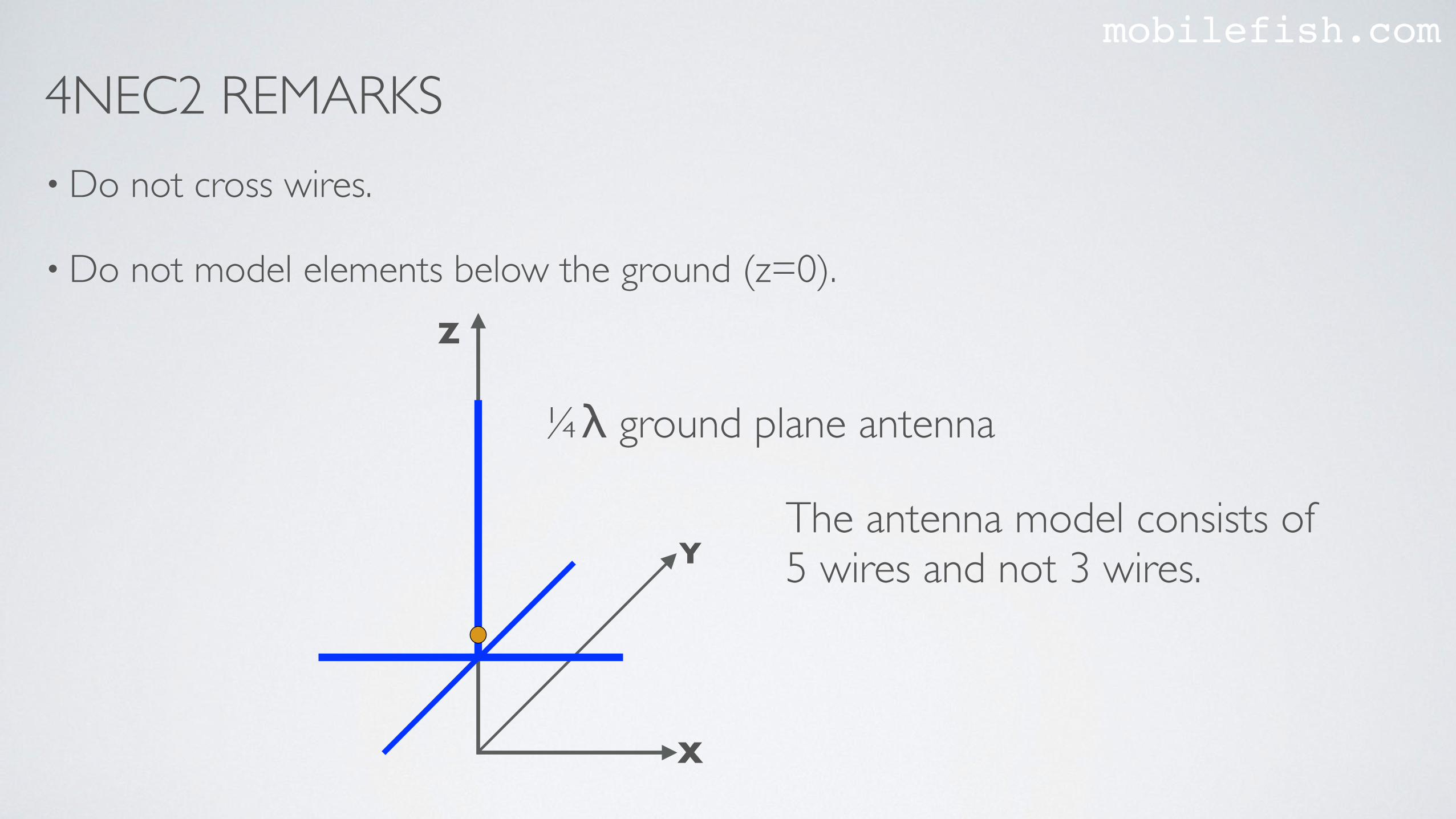
• Do not cross wires.
• Do not model elements below the ground (z=0).Z
X
Y
¼λ ground plane antenna
The antenna model consists of 5 wires and not 3 wires.
SOME INFORMATION ABOUT COCOANECmobilefish.com
• cocoaNEC has several limitations which other antenna modelling software does not have. For example: You can not model helixes in the spreadsheet, and helixes are not displayed in the 3D model.
• It is important to see all your antenna elements in 3D to verify if your antenna is correctly modelled.
• In cocoaNEC and 4NEC2 wire radius can be entered in American Wire Gauge format.For example: #12
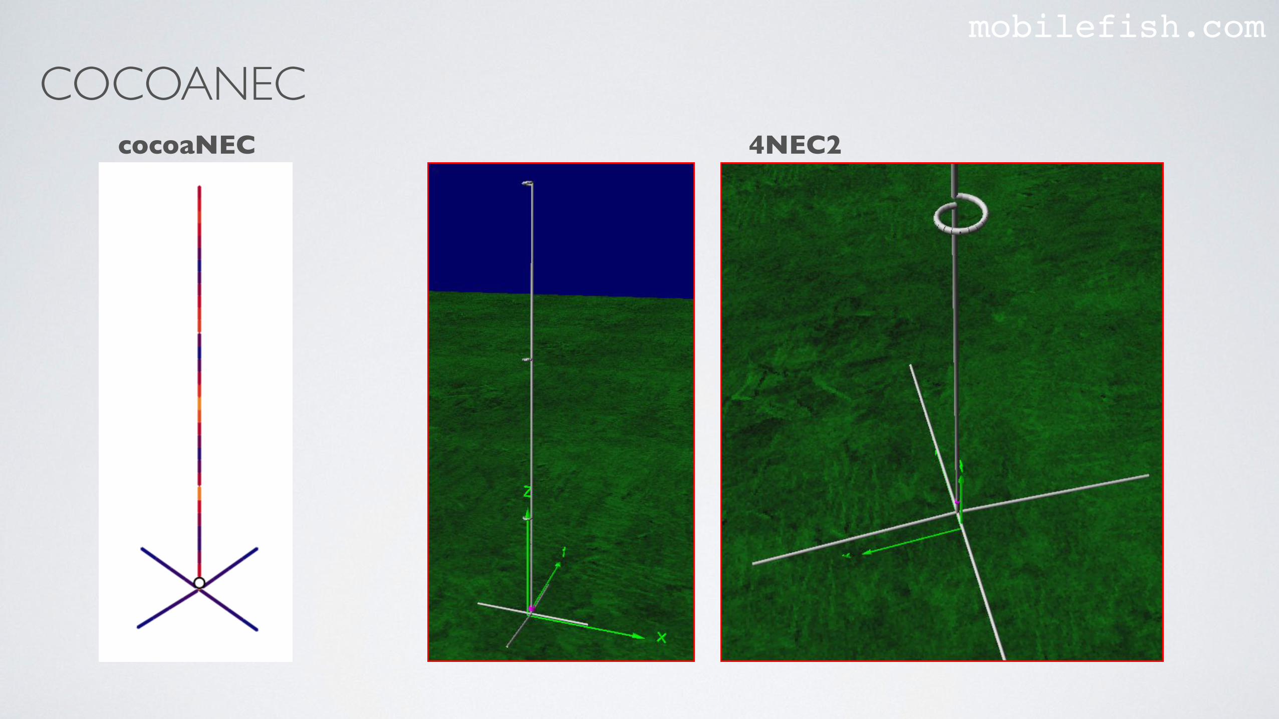
COCOANECmobilefish.com
cocoaNEC 4NEC2

MORE INFORMATIONmobilefish.com
• More information about 4NEC2:https://www.qsl.net/4nec2/


