LOV FRYER TECHNICAL REFERENCE MANUAL JAN 2008 Edition Introducing the LOV Fryer 1 The LOV Systems 2 M2007 11 RTI-equipped Systems 27 Board Replacement 32 Wiring Diagrams 34 Frymaster and Dean Technical Service 8700 Line Ave, Shreveport, LA 71106 Service Hotline: 800-551-8633 Website: www.frymaster.com *8196358*
Transcript
LOV F
RYER T
ECHNIC
AL
REFERENCE M
ANUAL
JAN 2008Edition
Introducing the LOV Fryer 1
The LOV Systems 2
M2007 11
RTI-equipped Systems 27
Board Replacement 32
Wiring Diagrams 34
Frymaster and Dean Technical Service8700 Line Ave, Shreveport, LA 71106Service Hotline: 800-551-8633Website: www.frymaster.com
*8196358*
LOV Technical Reference
�
The Low Oil Volume (LOV) fryer is a McDonald’s-only, feature-laden version of the RE fryer introduced in 2006. The enhancements found on the LOV fryer include:
• Low volume frypot —30 pounds (�5 liters) rather than 50 pounds (25 liters) of oil.
• Automatic top-off — the fryer automatically maintains an optimal oil level with a reservoir in the cabinet.
• M2007 computer — a sophisticated controller with multiple levels of programming.
• Automatic filtration — the fryer performs hands-free filtering at prescribed cook cycle counts or at prescribed times.
• Oil savings — The combination of a low-volume fry vat and oil automatically kept at a optimal level, reducing oil usage.
A similar fryer, the Protector, is available for the general market. It has the LOV’s auto top-off feature and the on-board oil reservoir, the smaller fry vat and the oil savings associated with smaller vat and the top-off feature.
Filtering using the CM7 computer on a Protector fryer is manual.
Introducing the Low Oil Volume FryerThe LOV fryer
M2007 Computer
Filter Light
Diagnostic LED Screen
Reset button
Replace JIB Light
JIB (behind right door)
The Protector Fryer
LOV Technical Reference
2
Auto Top Off
The core of the system is an automatic top-off board, which senses when the oil level is low and fills the pot to the top line.
The oil level is monitored by an RTD sensor in the frypot at the upper oil level. The oil is moved to the pot from a reservoir, called a JIB (Jug In Box), to the frypot with a small pump.
A circuit board, the ATO (Automatic Top Off), is located inside a box behind the JIB. It monitors the oil-level RTD and activates the pump when it senses an oil temperature drop of 60°F (33°C) below setpoint, indicating the oil has moved away from the sensor. The oil is pumped into a solenoid tree and the ATO opens the solenoid for the frypot that needs oil.
Oil is pumped into the tank until the ATO detects a temperature within 55°F (30°C) of setpoint.
The system is not suited to filling the frypot when it is empty and there are safeguards to prevent it from activating when the fryer is cold and the oil is resting at the lower position.
The system is not active until the oil in the frypot reaches 300°F (�49°C). That temperature is monitored by the probe. The activation of the system is handled by the fryer’s computer. In the McDonald’s system that is the M2007. The automatic top off system is also inactive during filter cycles.
The system works the same in McDonald’s gas and electric LOV systems and in the Protector fryer, which is made for the general market.
The level of the reservoir, or JIB, is monitored by the ATO and the M2007 computer. If a low oil condition is not rectified in 6 minutes, the low JIB light is illuminated on the front of the fryer.
The LOV Systems
LOW Oil RTD Oil top off
port
Auto Filtra-tion RTD
High limit
The solenoid tree and the pump, which move oil from the reservoir to the frypots, are visible above.
The ATO board controls the top off of the fry pots.
LOV Technical Reference
3
The ATO board is positioned in a box with the transformer, which provides power for the board. The box also may have a power switch, which allows the system to be shut off (switch removed in later models).
The reservoir, or JIB, rests behind the right door of the fryer. A light on the front of the fryer illuminates when the jug is empty.
Problem Probable Cause FixJIB light won’t illuminate.
Auto top off power switch is off. (switch removed in later models)No three-phase power in the contactor box/component box supplying the ATO box.Failed transformer in ATO box.Loose wire.
1.
2.
3.4.
Verify that the auto top off power switch is switched on. The switch is located behind the JIB on the left side of the auto top off control box. (switch removed in later models)Ensure power is present Check transformer output; replace if necessary.Check connection between JIB LED and J6 on ATO board.
1.
2.3.
4.
Only one vat tops off.
Failed solenoid.Loose wire connection.
1.2.
Check power to pump. A hot pump suggests a failed solenoid.Check wiring harnesses on ATO board and solenoids.
Oil trickles into the frypot from a port behind the elements in electric fryers. In gas fryers, it comes from a port on the foam deck. This part of the system is not designed to fill up the vat.
PortSensor
LOV Technical Reference
4
Problem Probable Cause FixNo vats topping off. Auto top off power switch off.
(removed in later models)ATO board power loss.Failed or over tightened pump.Failed transformer/harness.Probe temperature lower than setpoint.Oil viscosity too thick.Failed solenoid.Failed ATO board.
1.
2.3.4.5.
6.7.8.
Verify that the auto top off power switch is switched on. (removed in later models) The switch is located behind the JIB on the left side of the auto top off control box.Check solenoid to see if functioning properly.If the solenoid is working, ensure that the screws on the bottom of the pump are not too tight. Loosen the screws. If loosening the screws doesn’t fix the problem, replace the pump.Ensure transformer in ATO box is functioning properly. Check power from transformer to ATO board. Ensure all harnesses are plugged securely into place.Check to see that fryer is heating. Fryer temperature must be at least 300°F (149°C). Check probe resistance. If probe is bad, replace the probe.Ensure oil viscosity is thin enough to pump.Power to the ATO board has been cut off. Restore power to the board and cycle all computers off and on to readdress system.Check for proper voltages using the pin position chart found on pages 40-41 at the back of this manual. If ATO found defective, replace ATO board.
1.
2.
3.
4.
5.
6.7.
8.
LOV Technical Reference
5
(1) Responding Yes to the Blue LED filter prompt, sets in motion a filter cycle that lasts about as long as a cook cycle. Communication between the M2007 computer, the manual interface, or MIB board, and the automatic intermittent filtration, or AIF board, handle the process. (2) Linear actuators open and close the drain valve and return valve, (3) emptying and refilling the frypot.
Auto Filtration (MIB and AIF)
The auto filtration system is controlled by the M2007 computer, the AIF (Automatic Intermittent Filtration) board and the MIB (Manual Interface Board). The filtration is made hands-off by linear actuators operating the drain and return valves.
The computer is programmable, allowing filter cycles to be launched after a set number of cook cycles and a prescribed elapsed time.
The system can be set to lock out automatic filtration during busy times, such as the lunch rush.
The fryer prompts for filtration by flashing a blue LED on the front and a text prompt on the computer. The operator can say no; cooking can continue.
A Yes response leads to communication between the MIB and the AIF boards. The MIB is the more robust board. It controls and oversees the filtration; the AIF board operates the actuators, which open and close the valves.
The MIB is in the fryer cabinet and partially covered by a sheet metal cover. The reset button and the LED display are visible. Buttons behind the cover allow limited manual operation of the system and its valves. The cover should be reinstalled after service.
The LED displays codes that can be used to diagnose failures (see chart on page 44).
An AIF board is mounted under each fry vat.
1 2 3
LOV Technical Reference
6
Manual — Used to toggle between automatic and manual filtration mode. The unit must be in manual mode for the other MIB buttons to operate.
Select — Used to scroll through the vats, which are shown numerically in the LED.
Drain — Used to open and close the drain valve of the vat indicated on the display. When pressed an LED on the button indicates activity: slow blink, awaiting response from AIF; LED illuminated constantly, drain open; no illumination, drain closed; rapid blink, no response from AIF.
Return — Used to open and close the return valve on the vat indicated on the display. It also controls the pump. When pressed an LED on the button indicates activity: slow blink, awaiting response from AIF; LED illuminated constantly, drain open; no illumination, drain closed; rapid blink, no response from AIF. The pump turns off before closing the return valve; the return valve opens before the pump is turned on.
The mode display on the face of the MIB board displays a range of letters, which indicate activity or an error.
These codes are listed on the next page.
The MIB board
Mode DisplayShows status (auto or manual) vat number (when operating valves manuals) and dis-plays error codes.
Manual/AutoSwitches fryer from auto to manual operation.
ResetResets system, ensures all valves are closed.DrainOpens and closes drain valves in manual mode.
Vat SelectionSelects vat for manual operation of valves.
ReturnOpens and closes return valves and turns on filter pump in manual mode.
The MIB is mounted behind the left door. See arrow.
LOV Technical Reference
7
1-8 — Numbers corresponding to the vats.
A — Auto mode, auto fi ltration enabled.
C — Closed valve, display alternates between C and vat number. LED blinks.
d — Drain issue; display alternates between d and vat number.
E — Actuator circuit not sensing actuator; display alternates between E and vat number.(Ensure actuator is plugged in and in home position.)
F — Incomplete fi ltration; F alternates with n when the MIB doesn’t receive a complete fi ltration response from an AIF.
L —Loading; loading fryer confi guration. Shown during initial startup, rare otherwise.
n — Network error; n alternates with r, indicating a time-out on reset; n alternates with F, indicating an incomplete fi ltration response (see F above); n alternating with a vat number and a drain or return LED blinking; time-out error opening or closing a valve.
O — Open valve; O alternates with vat number and blinking LED.
P — Pan switch; fi lter pan is not in place or not sensed. Auto Filtration disabled.
U — Fry battery not confi gured; the MIB board is looking for a message from an M2007, allowing it to initialize the battery.
r - Reset; r alternating with a vat number indicates that the MIB board is resetting. If r is displayed without alternating with a vat number, a problem may exist with the MIB board itself.
Press the M button, which switches the board to manual. The display becomes the number of the vat to be controlled manually.
Press the vat selector button until the desired vat number is displayed.
Press either the drain or return button to drain or return oil to the vat displayed. Pressing both allows fi ltration.
Pressing the M button again returns the board to automatic mode.
�.
2.
3.
4.
Manual Draining, Filling, Filtering with MIB
2� 3
Error Codes
LOV Technical Reference
�
Problem Probable Cause FixAuto filtration won’t start.
Ensure MIB is not in manual mode.Ensure MIB cover is not pressing against buttons.Filter relay failed.
1.2.
3.
Ensure MIB is in “A” automatic mode and press the reset button.Remove and replace cover.Replace 24VDC filter relay (807-4482).
1.
2.3.
MIB doesn’t display A or vat number.
An error has occurred and dis-played character indicates error.
1. Check MIB Diagnostic codes, page 44 of this manual.
1.
No power at MIB. Transformer failed in left compo-nent box.
1. Check output on left transformer in left component box; should be 24VDC. If not, replace the transformer.
1.
MIB error will not clear.
Power surge or other electrical problem.
1. Press the reset switch, top right corner of the MIB, to reinitialize the CAN system. The reset takes about 20 seconds per vat. The MIB display should return to “A“, though it may take more than one minute to do so.
1.
MIB alternating “n” and “r”.
Network error on the CAN bus communication.
1. Ensure the CAN bus system is terminated at BOTH ENDS (on the M2007 connector J6 and on the ATO board connector J10) with a resistor equipped 6-pin connector.
Ensure all 6-pin CAN connectors are tight between the M2007 (J6 and J7), MIB (J1 and J2), AIF (J4 and J5) and ATO (J10) boards. Check continuity between each color wire on the CAN connectors into J7 on the far right computer and J10 on back of the ATO board (black to black, white to white, and red to red), and ensure there is no continuity between different color wires (black to red, red to white, and white to black).Ensure black computer locator wires are connected from ground to correct pin position (see diagram 805-1656 on page 35 of this manual). Ensure all boards have the corner ground wire attached and tightened.The locator pin in J2 of the AIF board is either loose or in the incorrect position. See the charts on pages 45-46 of this manual for proper pin position.In early units, it is possible that the resis-tor could short. Disconnect power to the unit, unwrap the resistor leads, and ensure they are not touching.
1.
•
•
•
•
•
Troubleshooting the Manual Interface Board (MIB)
LOV Technical Reference
9
MIB displays incorrect number of vats.
Network is not terminated correctly.Wiring harnesses are loose or damaged.Locator pin issue.
1.2.
3.
Ensure the CAN bus system is terminated at BOTH ENDS on the M2007 connector J6 and on the ATO board connector J9) with a resistor equipped 6-pin connector. In early units, it is possible that the resistor could short. Disconnect power to the unit, unwrap the resistor leads, and ensure they are not touching.Unplug and reseat all wiring harnesses in CAN system. Check resistance between pins 2 and 3 on the CAN network connec-tors. If checking with resistor at the end, reading should be 120 ohms.The locator pin in J2 of the AIF board is either loose or in the incorrect position. See the charts on pages 45-46 of this manual for proper pin position.
1.
2.
3.
M2007 display shows Filter Error.
A filter error has occurred. It can be caused by a clogged filter pad, clogged filter pump, filter pump thermal overload or an actuator failure.
1. Follow the on-screen directions according to the flowchart on page 27 of this manual to clear the error. The underlying problem must also be corrected.
1.
LOV Technical Reference
�0
Troubleshooting the AIF System (AIF)
Problem Probable Cause FixActuator doesn’t function.
Actuator unplugged.AIF board failure.Actuator is bad.
1.2.3.
Ensure actuator leads are plugged into AIF board (J1 for FV, J3 for DV).Check the power on the connector of the problem actuator while manually opening or closing the actuator. Pins 1 (black) and 4 (white) should produce +24VDC when the actuator is opening; -24VDC should be read from Pins 2 (red) and 4 (white) when the actuator is closing. If either voltage is missing, the AIF board is likely bad. Test the actuator by plugging into another connector to open or close.If the actuator operates, replace the board.If proper voltages are seen at the connector and the actuator doesn’t operate, replace the actuator.
1.
2.
3.
Wrong vat drain opens.
Actuator is plugged into wrong connector.Locator pin is in wrong position.
1.
2.
Ensure the actuator is plugged into the correct connection (J1 for FV, J3 for DV).Ensure the locator pin is in the proper position in plug J2. See charts on pages 38-43 of this manual for proper pin position.
1.
2.
LOV Technical Reference
��
M2007 Computer
Overview
The M2007 computer retains the one-button ease of the M2000 and M100B, combining it with the utility of 40-product menu capability. It will operate with electric and gas fryers, and both full- and split-vat.
On single product vats, press any of the cook cycle buttons to begin cooking. On multi-product vats, press a product button and then a cook cycle button under the display showing the desired product name.
For example, a typical the M2007 computers on a 3-vat fry station will display FR FRIES. Pressing one of the cook cycle buttons will begin a cook cycle for French fries.
The chicken/filet station will usually display dashed lines [----]. Pressing the product button assigned to McChicken, for example, will cause mcchick to be displayed. Then, press a cook cycle button beneath the word mcchick to start a cook cycle for McChicken.
---- ---- ---- ---- MCC HICK MCC HICK
Product Buttons Cook Cycle Buttons
ON/OFF ON/OFFProduct Buttons
Filter, Temp, Info, Programming and Navigation Buttons
Cook Cycle and Selection Buttons
Heat Indicator Lamp
LED Display LED Display
LOV Technical Reference
�2
Navigation
The menu on the M2007 uses and 56 buttons to navigate the various menus and submenus.
When programming, the left screen shows a menu or submenu item. The right screen is for data entry. Data is entered with alpha-numeric characters, scrolling through lists or by toggling between choices (see diagrams on previous page). During programming if a button is not pushed within one minute, the computer returns to operation mode.
Cook Cycle and Selection Buttons
The ü and û buttons are dual-function buttons shared with the number � and 2 buttons. They are located directly below the LED displays (see diagrams on previous page). Use these buttons to select or cancel functions. The û button is used to back out of and quit submenus.
Filter, Temperature, and Info Buttons
The < FLTR and FLTR > buttons (see diagram) are used to filter the left and right vats of a split vat fryer on demand, while the right FLTR > button is used to filter a full vat on demand. The FLTR buttons, if pressed once, will display the amount of cook cycles remaining until a filtration prompt. When the FLTR button is pressed twice, the date and time of the last filter will be displayed.
Temp Button
The TEMP button, if pressed once while the fryer is on, displays current vat temperature on both sides. If the TEMP button is pressed twice while the fryer is on, it shows the setpoint temperatures of the vats. If the fryer is off, the display shows the current versions of software.
Info Button
The INFO button, if pressed once when the fryer is on, shows the recovery time for each vat from the last test. Recovery displays the time required for the fryer to raise the temperature of the oil 50°F (28°C) between 250°F (121°C) and 300°F (149°C). If the INFO button is pressed and held for three seconds it shows information such as usage, filter statistics and last cook cycles.
LOV Technical Reference
�3
Basic Operation
Turn Fryer ONPress right key for full pot; press key on desired side on a split pot.
Turn Fryer OFFPress right key for full pot; press key on desired side on a split pot.
Check Frypot TemperaturePress Temp key once. Displays show frypot temperatures.
Start Two-Button Cook Cycle (Multi-Product Mode)Press product key bearing icon for desired product. Press cook channel button to begin cook cycle.
2
Cancel Duty or Remove Alarm
Press key under active display.
2
TEMP
TEMP
Press product key bearing icon for desired product.Press cook channel button under display showing desired item until beep is heard (approx 3 seconds).
2
Change From Dedicated to Multi-Product Mode
Press and hold Cook Channel button under displayed menu item for approximately 3 seconds until beep is heard.Display changes to dashed lines.
2
Change From Multi-Product Mode to Dedicated Mode
Filter, Temp, Info, Programming and Navigation Buttons
Cook Channeland Selection Buttons
ON/OFFON/OFF Product Buttons
LOV Technical Reference
�4
Cooking With Multi-Product Display
Press a product button.
Vat with appropriate setpoint displays:skip to step 5.
If a duty is required for this menu item, duty is displayed when it is time to perform a duty, such as shake.
duty
Pull is displayed when the cook time is complete; an alarm sounds.
pull
Mc chick
Press a cook channel button to begin cook cycle.
1
2
3
4
5
6
7
8
9
Vat with inappropriate setpoint displays: <<<<>>>>
1
Display alternates between MCCK and remaining cook time.
Dashed lines appear in both displays. - - - - - - - -
Dashed lines reappear under active display at the end of the cook cycle.
- - - - - - - -
Press cook channel button under duty display to cancel alarm.
10
Mc cK
2:34
Press cook channel button under pull display to cancel alarm.
11
McCK
2
2
If this occurs, change setpoint by pressing the button assigned to the product.
McCK
When the chevrons appear, immediately press and hold cook button until a beep is heard (approximatelythree seconds).
<<<<>>>>
1
NOTE: If error REMOVE DISCARD appears, press and hold cook button under message to remove error message.
LOV Technical Reference
�5
Cooking With Dedicated Display
QA is displayed when the quality time has elapsed.
QA
Pressing the cook channel button restores the display to FR FRIES and the unit is ready for cooking
.
FR FRies
Pressing the cook channel button now will launch a cook cycle and end the quality countdown.2:34
1
9
10
11 1
Press a cook channel button to begin the cook cycle.
12
Display alternates between abbreviated product name and remaining cook time.
3FRis
Duty is displayed when it is time to shake the fry basket.
duty4
1Press cook channel button to cancel alarm.
6
5
Pull is displayed when the cook cycle is complete.
pull
Press cook channel button to cancel alarm.
1
7
A menu item, such as FR FRIES shows in display
1 frfries
Q7 is displayed and alternates with FRIS. As the quality time counts down.
Q7 Fris
Q1 Fris8
Fr fries
LOV Technical Reference
�6
Press and quickly release product button for french fries.
<<<<<>>>>>
1
Computer will change from Hash Brn to <<<<<>>>>>;an alarm will sound.
Press and hold the cook channel button under the display until a beep is heard.Display changes to FR Fries. fr frieshash brn
Changing from Breakfast Setup to Lunch
1
2
3
4
Change both displays to FR FRIES
FFRY
Hash brn Hash brn
LOV Technical Reference
�7
Press and quickly release product button for hash browns.
<<<<<>>>>>
1
Computer display will change fromFR Fries to <<<<<>>>>>; analarm sounds.
Press and hold the cook channel button under the display until a beep is heard.Display changes to Low Temp until setpoint is reached.
LOW temp
fr fries
Changing from Lunch Setup to Breakfast
1
2
3
4Computer displays FR FRies
5Ha
sh
brn
Display changes to Hash Brn. hash brn6
Fr friesFr fries
LOV Technical Reference
��
Filter Menu................................................................................................ 4.11 [Press and hold FLTR ►]
Auto Filter Maint Filter Dispose Drain to Pan Fill Pot from Drain Pan Fill Pot from Bulk
Programming Level 1 Program ............................................................................. 4.12 [Press and hold TEMP and INFO buttons, 2 beeps, displays Level 1]
Product Selection ................................................................ 4.12.1 Name Cook Time Temp Cook ID Qual Tmr Duty Time 1 Duty Time 2 AIF Disable Assign Btn AIF Clock ............................................................................ 4.12.2 Disabled Enabled Deep Clean Mode ............................................................... 4.12.3 High-Limit Test .................................................................... 4.12.4 Hi-Limit Test 1 Hi-Limit Test 2 Fryer Setup ......................................................................... 4.9
Level 2 Program (Manager Level) .................................................. 4.13 [From Level 1, press and hold TEMP and INFO buttons, 3 beeps, displays Level 2]
Prod Comp Sensitivity for product .................................. 4.13.1 E-Log Log of last 10 error codes ....................................... 4.13.2 Passwords Change passwords ..................................... 4.13.3 Setup Usage Level 1 Level 2 Get Mgr (to be removed in v. 48) Alert Tone Volume and Tone ............................................. 4.13.4 Volume 1-9 Tone 1-3 Filter After Sets number of cooks before filter prompt ........ 4.13.5 Filter Time Sets amount of time between filter cycles ......... 4.13.6
Tech Mode [Press and hold ◄ and ► for 10 seconds, 3 beeps, displays code, enter1650]
Clear Passwords Clear Signature Filter Pad Time Service Required (to be introduced in v. 48)
Info Mode ................................................................................................... 4.14 Full/Split Vat Configuration Filter Stats ........................................................................... 4.14.1 Review Usage ..................................................................... 4.14.2 Last Load ............................................................................ 4.14.3
M2007 Menu Items Location in IO manual
The following chart maps the menu options available in the M2007 computer and indicates the loca-tion of more information on each menu item within the LOV Fryer Installation and Operation Manu-al. For more information, consult the indicated section.
LOV Technical Reference
�9
Loading and Updating Software
Loading Software from an SD card to MIB and AIF boards
To update MIB or AIF software in the field follow these steps:
1. Switch all computers to OFF. With the computer displaying OFF, press the TEMP button to check current M2007/MIB/AIF software version.
2. Remove the two screws on the right side cover plate of the MIB board. 3. With the MIB displaying A insert the SD card with the new software, with the card contacts
facing out and the notch on the bottom left, into the slot on the right side of the MIB board.
4. Once inserted, watch for a period in the display to appear on the bottom right of the MIB dis-play, indicating the software is being downloaded. If a period does not appear, the software on the card and on the computer may be the same version, or the boot loader software missing or corrupt. It will not update. If this happens, contact Frymaster.
5. The period blinks several times while loading. Wait for a minimum of two minutes and the
period in the display stays off.
6. Remove the SD card from the MIB.
7. If only updating the MIB or AIF boards remove power from the MIB by carefully removing the16-pin harness behind the MIB board or the five-pin control power cord on the rear of the unit. If updating all the software update the MIB and then the M2007 and then remove all power from the fryer using the five-pin control power cord on the rear of the unit.
8. Restore power to the MIB to reboot the system.
9. A successful upgrade is confirmed by a “cLc” display on the MIB board upon restart followed by “r, 1, r, 1, r, 2, r,” etc., ending with A. If this does not happen, try reloading the software.
�0. Verify software upgrade by pressing the TEMP button with the computer OFF to check the updated MIB/AIF version.
Insert the SD card with contacts facing the front of the fryer.
Remove the SD card using the fingernail slot on the top of the card.
LOV Technical Reference
20
Loading Software from an SD card to an M2007 Computer
To update M2007 computer software in the field, follow these steps:
1. Switch all computers to OFF. With the computer displaying OFF, press the TEMP button to check current M2007/MIB/AIF software version.
2. With the computer displaying OFF, remove the two screws on the left side cover plate of the M2007 board.
3. With the computer folded down and the MIB displaying A, insert the SD card, with the con-
tacts facing down and the notch on the bottom right (see images below), into the slot on the left side of the M2007.
4. Once inserted, FWUPD appears on the left display and SCCRCOK appears on the right. Numbers count up on the right display.
5. The display then changes to FWLOAD on the left; numbers count up on the right.
6. The computer displays OBFCRC. If updating ATO software the computer will display FWU ATO on the left and will count down from 2500 on the right.
7. When the update is complete the M2007 displays DONE on the left and RM SDCRD on the right.
8. Remove the SD card using the fingernail slot on the top of the SD card.
9. If updating the M2007 or ATO board, remove power to the M2007 by removing the 20-pin J2 plug on the rear of the computer, or re-move power to the fryer to reboot the computer. If updating all the software update the MIB and then the M2007 and then remove all power from the fryer using the five-pin control power cord on the rear of the unit.
�0. Restore power to the M2007 – There is short delay prior to the computer powering up and displaying OFF.
��. Repeat steps �-�0 for all computers.
�2. With the computer displaying OFF, verify software update by pressing the TEMP button to check updated M2007/MIB/AIF ver-sion.
13. If the software is adding fields that require passwords, enter Level 2 mode and change passwords.
Insert the SD card with con-tacts facing up.
Remove the SD card using the fingernail slot on the top of the card.
LOV Technical Reference
2�
M2007 Troubleshooting
Problem Probable Causes Corrective Action
No display on computer.
A. Computer not turned on. A. Press the ON/OFF switch to turn the computer on.
B. No power to the fryer.
B. This fryer has two cords: a computer power cord and a main power cord. If the computer cord is not plugged in, the computer will not activate. Verify computer power cord is plugged in and that circuit breaker is not tripped.
C. Computer has failed.
C. Swap the computer with a computer known to be good. If computer functions, replace the computer.
D. Damaged computer wiring harness.D. Swap with a harness known to be good. If computer functions, replace the harness.
E. Power supply component or interface board has failed.
E. If any component in the power supply system (including the transformer and interface board) fail, power will not be supplied to the computer and it will not function.
Computer locks up. Computer error.Power cycle the computer using the master switch on the component box next to the fuse.
M2007 display shows filter busy.
Another filtration cycle is still in progress.
A. Wait until the previous filtration cycle ends or an error is cleared to start another filtration cycle.B. Press reset button on the MIB board and wait at least 60 seconds. Computer should clear and return to normal operation once complete.
M2007 display shows REMOVE DISCARD.
In non-dedicated mode a product is dropped that has a different setpoint than the current vat temperature.
Remove and discard product. Press and hold the cook button for three seconds under the display with the error to remove the error. Reset the setpoint of the vat before trying to cook product.
M2007 display shows CHK PAN.
A. Filter pan is not fully set into fryer.
B. Missing filter pan magnet.
C. Defective filter pan switch.
A. Pull filter pan out and fully reinsert into fryer.B. Ensure the filter pan magnet is in place and if missing replace.C. If the filter pan magnet is fully against the switch and computer continues to display chk pan, switch is possibly defective.
LOV Technical Reference
22
Problem Probable Causes Corrective Action
M2007 display is in wrong temperature scale (Fahrenheit or Celsius).
Incorrect display option programmed.
M2007 computers may be pro-grammed to display in either Fahr-enheit or Celsius. Press and hold and simultaneously until code appears. Enter 1658. The com-puter displays OFF. This toggles the temperature from F° to C° or vice versa. Turn the computer on to check temperature and see the temperature scale. If the desired scale is not displayed, repeat.
M2007 display shows hot hi 1.
Frypot temperature is more than 410ºF (210ºC) or, in CE countries, 395ºF (202ºC).
This in an indication of a malfunc-tion in the temperature control circuitry, including a failure of the high-limit thermostat.
M2007 display shows HI-LIMIT. Computer in high-limit test mode.
This is displayed only during a test of the high-limit circuit and indicates that the high-limit has opened properly.
M2007 display shows low temp.
Frypot temperature is between 180°F (82°C) and 315°F (157°C).
This display is normal when the fryer is first turned on while in the melt cycle mode. To bypass the melt cycle press and hold a #2 product button under the LCD display until a chirp is heard. The alarm will chirp and the computer displays EXIT MELT alternating with YES NO. Press the #1 YES button to exit melt.
The fryer may temporarily show low temp when a large batch of product is added to the frypot. However, if low temp is shown constantly, the fryer may not be heating.
M2007 display shows PROBE FAILURE.
Problem with the temperature measur-ing circuitry including the probe.
This indicates a problem within the temperature measuring circuitry that is beyond the scope of operator troubleshooting.
M2007 display shows PROBE FAILURE with alarm sounding.
Damaged computer wiring harness or connector.
Swap the computer wiring harness with one known to be good. If problem is connected replace harness.
M2007 display shows IGNITION FAILURE.
Open drain valve, failed computer, failed interface board, open high-limit thermostat.
This indicates that the fryer is not heating. It is displayed if the fryer loses its ability to heat oil. It is also displayed when the oil temperature is above 450°F (232°C) and the high-limit thermostat has opened, halting the heating of the oil. Verify that the drain valves are fully closed.
LOV Technical Reference
23
Problem Probable Causes Corrective ActionComputer will not go into pro-gram mode or some buttons do not actuate.
Failed computer. Replace computer.
M2007 display shows HI 2 BAD. Computer in high-limit test mode.
This is displayed only during a test of the high-limit circuit and indicates that the high-limit has failed.
Heat indicator off upon initial startup. Display shows hi or hot with alarm sounding.
Failed computer. Replace computer.
M2007 display shows igni-tion FAILURE with alarm sounding. Heating indicator is on, but fryer is not heating.
Drain valve not fully closed.
Press the reset switch on the MIB board. All drain valves should close. Using the ON/OFF switch, turn the computer OFF and then ON again.
M2007 display shows IGNI-TION FAILURE and alarm sounds, but fryer operates normally (false alarm).
Failed computer. Replace computer.
M2007 display shows low temp, heating indicator cycles on and off normally but, fryer does not heat.
A. Failed computer.
B. Damaged computer wiring harness.
A. Replace computer.
B. Replace computer wiring harness.
M2007 display shows Filter error.
A filter error has occurred due to dirty or clogged filter pad or paper, clogged filter pumps, filter pump thermal overload, or an actuator problem.
Enter the MGR CODE (1234) and follow the steps on the flowchart on page 27 of this manual.
M2007 display shows soft-ware for only M2007 or MIB but not all boards.
Loose or damaged harnessCheck that all harnesses between M2007s, MIB, AIF and ATO are secure.
M2007 display shows ERROR RM SDCRD (only appears when an error occurs while loading software into the computer).
Defective SD Card Replace card with another card.
LOV Technical Reference
24
Useful Codes
To enter any of the following codes: Press and hold and simultaneously for TEN seconds and a third chirp sounds. Release the buttons and code appears.
• Reset Factory Menu - Enter 3322. The computer display flashes and quickly counts from �-40 and switches to off. (NOTE: This will delete any hand-entered menu items).
• Reset CALL TECH Message - Enter 1000. Computer display switches to off.
• Change from F° to C° - Enter 1658. The computer displays off. Turn the computer on and check temperature to see the temperature scale. If the desired scale is not displayed, repeat.
• Enter Tech Mode - Enter 1650.
• Readdress LOV configuration after changing an MIB board – Enter 2007.
Passwords
• To enter level one, level two passwords: Press and hold the TEMP and INFO buttons simultaneously until level � or level 2 is displayed. Release the buttons and ENTER Code appears.
• Fryer Setup, Level One, Level Two and Get Manager Password - Enter 1234.
• Usage Password - Enter 4321.
Tech Mode
Tech mode allows technicians to reset passwords set in levels one and two. It also resets the time and date. It also allows the technician to access the fryer main setup mode.
�. Press and hold and simultaneously for TEN seconds until a third chirp is heard and CODE is displayed.
2. Enter 1650.
3. The computer displays TECH MODE and changes to CLEAR PASSWORDS.
4. Press the ü (�) button to accept selection and clear the passwords.
5. The computer displays CLEAR PASSWORDS on the left and COMPLETE on the right. This clears any passwords set up under levels one and two.
6. Press the 6button to toggle to CLEAR SIGNATUre.
LOV Technical Reference
25
Fryer Setup Mode
Setup mode allows technicians to set the time, date, temperature format, language, fryer type, vat type and oil system.
�. With the computer displaying OFF, press and hold the TEMP and INFO buttons until LEVEL 1 is displayed.
2. Press the TEMP key once to FRYER SETUP.
3. The computer displays FRYER SETUP and then changes to ENTER CODE.
4. Enter 1234.
5. Press the ü (1) button to accept selection.
6. The computer displays TIME FORMAT on the left and 12 HR on the right.
7. Press the button to toggle between 12 HR and 24 HR time formats.
�. Press the ü (1) button to accept selection.
9. The computer displays ENTER TIME on the left and HH:MM on the right.
10. Enter the time in hours and minutes using the 0-9 keys.
��. Press the ü (1) button to accept selection.
�2. The computer displays ENTER TIME on the left and am on the right.
�3. Press the button to toggle between am and PM if 12 HR time format was chosen.
�4. Press the ü (1) button to accept selection.
�5. The computer displays DATE FORMAT on the left and US on the right.
7. Press the ü (�) button to accept the change.
�. The computer displays CLEAR SIGNATUre on the left and COMPLETE on the right. This resets the date and time. (NOTE: This will delete any hand-entered menu items.)
9. Press the 6button to toggle to FILTER PAD TIME on the left and 25 on the right. (25 hours is the default time to change the pad)
�0. Press the û (2) button to accept changes and exit.
��. The computer displays OFF. Proceed to the next page to enter the setup mode.
LOV Technical Reference
26
�6. Press the button to toggle between US and INTERNTL time formats.
�7. Press the ü (1) button to accept selection.
��. The computer displays enter date on the left and MM-DD-YY or DD-MM-YY on the right.
19. Enter the date using the 0-9 keys.
20. Press the ü (1) button to accept selection.
2�. The computer displays language on the left and English on the right.
22. Press the button to toggle between ENGLISH, FRENCH, FRENCH CANADIAN, SPANISH, PORTUGUESE, GERMAN and SWEDISH languages.
23. Press the ü (�) button to accept selection.
24. The computer displays FRYER TYPE on the left and ELEC on the right.
25. Press the button to toggle between ELECTRIC and gAS fryers.
26. Press the ü (�) button to accept selection.
27. The computer displays VAT TYPE on the left and SPLIT on the right.
2�. Press the button to toggle between SPLIT and fULL vats.
29. Press the ü (�) button to accept selection.
30. The computer displays oIL SYSTEM on the left and JIB on the right.
3�. Press the button to toggle between JIB and BULK oil systems.
32. Press the ü (�) button to accept selection.
33. The computer displays TEMPERATURE on the left and F on the right.
34. Press the button to toggle between F° and C° temperature scales.
35. Press the ü (�) button to accept selection.
36. The computer displays FRYER Setup for three seconds and the computer displays OFF on both sides.
LOV Technical Reference
27
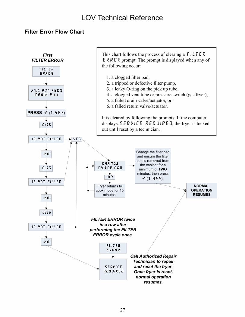
Filter Error Flow Chart
This chart follows the process of clearing a Filter Error prompt. The prompt is displayed when any of the following occur:
1. a clogged filter pad,2. a tripped or defective filter pump,3. a leaky O-ring on the pick up tube,4. a clogged vent tube or pressure switch (gas fryer),5. a failed drain valve/actuator, or6. a failed return valve/actuator.
It is cleared by following the prompts. If the computer displays Service Required, the fryer is locked out until reset by a technician.
Change the filter padand ensure the filterpan is removed from
the cabinet for aminimum of TWO
minutes, then press (1 ).
Fryer returns tocook mode for 15
minutes.
NORMALOPERATIONRESUMES
PRESS (1 )
FILTER ERROR twicein a row after
performing the FILTER ERROR cycle once.
Call Authorized RepairTechnician to repair and reset the fryer.Once fryer is reset,normal operation
resumes.
FirstFILTER ERROR
LOV Technical Reference
2�
RTI-equipped SystemsSome stores may be equipped with RTI oil storage systems. If so, some of the settings, wiring, and troubleshooting may differ from normal LOV fryer systems. (See next page for bulk oil wiring.)
Normal measurements (MIB J6 8 pin connector with everything connected)
AC voltage measurements: - Pin � to Pin 2 - 24 VAC. - Pin 2 to Pin 3 - 24 VAC when RTI add pump switch is on, 0 VAC when it is off. - Pin 2 to Pin 4 - 24 VAC when RTI waste valve is on, 0 VAC when it is off. - Pin 6 to Pin 7 - 24 VAC when RTI JIB valve is on, 0 VAC when it is off.
DC voltage measurements: Pin 1 to Pin 8 - 0 VDC when waste tank is full, 5 VDC when it is not full. Troubleshooting The valves and pump should be off while MIB is resetting, roughly 5 seconds after a power on or after pressing the reset button; if any of the valves or pumps are on during reset then the MIB board is bad or wires are shorted. If JIB valve is not opening, measure when JIB valve supposed to be open:
1. Voltage at MIB board from Pin 1 to Pin 2, should be 24 VAC; if not, check connections from RTI 24VAC transformer and check transformer at RTI.
2. Voltage at MIB board from Pin 6 to Pin 7, should be 24 VAC; if not, check MIB board is bad or wires to JIB valve are shorted or both.
3. Voltage at JIB valve, should be 24 VAC; if not, check wiring from MIB board. If waste valve is not opening, measure when Waste valve is supposed to be open:
1. Voltage at MIB board from Pin 1 to Pin 2, should be 24 VAC; if not, check connections from RTI 24VAC transformer and check transformer at RTI.
2. Voltage at MIB board from Pin 4 to Pin 5, should be 24 VAC; if not, check MIB board is bad or wires to Waste valve are shorted or both.
3. Voltage at Waste valve, should be 24 VAC; if not, check wiring from MIB board. If Add pump is not operating, measure when add pump is supposed to be on:
1. Voltage at MIB board from Pin 1 to Pin 2, should be 24 VAC; if not, check connections from RTI 24VAC transformer and check transformer at RTI.
2. Voltage at MIB board from Pin 2 to Pin 3, should be 24 VAC; if not, check MIB board is bad or wires to pump relay are shorted or both.
Waste full signal: Pin � to Pin � should be 0 VDC when full, 5 VDC when not full; if no level change, then the connection from RTI switch or MIB board is bad.
•
•
LOV Technical Reference
29
TES
TIN
G B
ETW
EE
N P
INS
1 &
8
SH
OU
LD R
EA
D:
0V
DC
WH
EN
RTI
TA
NK
IS F
ULL
5VD
C W
HE
N R
TI T
AN
K IS
NO
T FU
LL
BLA
CK
24V
AC
IN F
RO
M R
TI (H
OT)
WH
ITE
24V
AC
IN F
RO
M R
TI (C
OM
) G
RE
EN
24V
AC
OU
T R
TI P
UM
P
BR
OW
N 2
4VA
C O
UT
WA
STE
SO
L.
DE
-EN
ER
GIZ
ED
– P
OT
EN
ER
GIZ
ED
- JIB
5-C
ON
DU
CTO
R
RE
D
BLA
CK
24V
AC
IN F
RO
M R
TI (H
OT)
WH
ITE
24V
AC
IN F
RO
M R
TI (C
OM
)
BR
OW
N 2
4VA
C O
UT
WA
STE
SO
L.
GR
EE
N R
TI J
IB V
ALV
E
RE
D
Bulk Oil LOV Wiring
LOV Technical Reference
30
Oil Disposal and Fill with RTI-equipped Systems
Bulk oil systems have large oil storage tanks, typically located in the rear of the restaurant, that are connected to the rear manifold on the fryer. Waste oil is pumped from the fryer, through the fitting located on the right, to the disposal tanks and fresh oil is pumped from the tanks, through the fitting located on the left, to the fryer (as shown below).
LOV fryers equipped for use with bulk oil systems have an onboard fresh oil jug with two fittings. The rear fitting is used for filling the jug and the front fitting is for topping off the frypot from the jug.
A momentary switch located inside the door adjacent to the JIB allows the operator to fill the JIB from the bulk oil storage tank. To fill the JIB, press and hold the add switch until the JIB is full then release.
Fittings, LOV Fryer.
Warning: Do not add HOT or USED oil to the JIB.
The RTI JIB.
RTI momentary switch.
Fresh Oil Connection Waste Oil
Connection
LOV Technical Reference
3�
Dispose to Waste, Refill Pot From Bulk
1. Hold down “filter” button until computer beeps twice.
2. Scroll down to “dispose” using “Info” button then press “ü” button to select.
3. Select “Yes” by pressing “ü” to dispose of oil in pot (this is a timed function).
4. “Vat Empty” is displayed.
5. Select “Yes” (by pressing “ü”) if it is empty or “No” (by pressing “û”) if vat still has oil.
6. “Clean Vat Complete” is displayed.
7. Press “ü” if vat is clean (oil disposes automatically for 60 seconds, if this is selected) and “û” if it is not clean and needs to be.
8. “Engage Dispose Switch” is displayed. Change the RTI switch to dispose. If the waste tank is full, the computer displays “RTI Tank Full.” Call RTI.
9. Press the “ü” to start disposal. “Pan to Waste” displayed. The pump will run for 60 seconds.
10. “Pan Empty” is displayed.
11. Press “ü” if oil in filter pan is empty. Select “û” if pan still has oil in it, and the pump will run for an-other 60 seconds.
12. “Disengage Dispose Switch” is displayed. Switch off the RTI dispose switch.
13. Press “ü” when RTI dispose switch is off.
14. “Fill Pot From Bulk” is displayed.
15. Press and hold “ü” if you wish to fill pot.
16. Release “ü” once pot is at desired level.
17. Press “û” to Exit program.
Dispose to Waste
1. Hold down “filter” button until computer beeps twice.
2. Scroll down to “dispose” using “Info” button and press “ü” button to select.
3. Select “Yes” by pressing “ü” to dispose of oil in pot (this is a timed function).
4. “Vat Empty” is displayed.
5. Select “Yes” (by pressing “ü”) if it is empty or “No” (by pressing “û”) if vat still has oil.
6. “Clean Vat” is displayed.
7. Press “ü” if vat is clean (oil disposes automatically for 60 seconds, if this is selected) and “û” if it is not clean and needs to be.
LOV Technical Reference
32
8. “Engage Dispose Switch” is displayed. Switch the RTI switch to dispose.
9. Press the “ü” to start disposal. “Pan to Waste” displayed.
10. “Pan Empty” is displayed after 60 seconds.
11. Press “ü” if oil in filter pan is empty. Select “û” if pan still has oil in it, and pump will run for another 60 seconds.
12. “Disengage Dispose Switch” is displayed. Switch off the RTI dispose switch.
13. “Fill Pot From Bulk” is displayed.
14. Press “û” if you wish to leave pot empty and exit program.
Fill Pot From Bulk
1. Hold down “filter” button until computer beeps twice.
2. Scroll down to “Fill Pot From Bulk.”
3. Press and hold “ü” if you wish to fill pot.
4. Release “ü” once pot is at desired level.
5. Press “û” to Exit program.
Fill Jug From Bulk
1. When “Yellow” LED indicator light is on, the pot top-off jug is empty.
2. To refill jug press ADD button on the RTI box located on back side of door that accesses jug.
3. Hold down button until oil is to desired level in jug.
4. Press the JIB reset button above the jub to turn the yellow LED off and renegage the ATO system.
Jug and Vat Won’t Fill
1. Enter FLTR MENU by pressing and holding the FLTR BUTTON.
2. Scroll to FILL POT FROM BULK. Press 1.
3. Computer displays FILL POT FROM BULK/YES NO. Press 1.
4. When the actuator opens, press 1 briefly again. Press 2.
5. Try to fill pot or JIB to see if issue resolved. If not, contact RTI.
LOV Technical Reference
33
Board ReplacementATO Replacement
The ATO board is located inside the box behind the JIB. It is connected to three phase power in elec-tric fryers and should be approached with extra caution.
�. Disconnect the fryer from the electrical power supply.
2. Locate the ATO box behind the JIB (Jug In Box).
3. Remove the cover to expose the transformer and ATO board.
4. Mark and unplug any wires or harnesses.5. Replace the defective component and reattach
all wires or harnesses. 6. Replace the cover, then reconnect the power. 7. Turn power off and back on to all computers
after power has been restored to the ATO board.
MIB Replacement
The MIB controller is located inside the left cabinet (see image below). In normal operation, a cover hides the MIB controls. The LED display is visible.
�. Disconnect the fryer from the elec-trical power supply.
2. Remove the three torx screws from the MIB cover, exposing the MIB board (see image at right).
3. Removing the four nuts in the corners of the board will expose the connections on the back of the board.
4. Disconnect the MIB board and care-fully remove the plugs on the rear of the board (see image at right).
5. Replace with a new MIB board and reverse steps to reassemble.
6. Once replaced, reconnect the power. MIB controller cover (three screws hold it in place).
1 screw
2 screwsCover
LOV Technical Reference
34
The MIB must be readdressed to the system after replacement. This procedure can be done from any one M2007 computers in the bank.
�. Readdress the fryer by pressing and hold-ing and simultaneously for TEN seconds until a third chirp is heard and code appears.
2. Enter 2007. The MIB display will display L for several seconds followed by the vat number alternating with “r” until the read-dress is complete.
3. When the readdress is finished, the MIB board will display A.
AIF Replacement
The AIF boards are located inside a protective housing underneath each frypot.
�. Disconnect the fryer from the electrical power supply. 2. Locate the AIF board to be replaced under a frypot. 3. Mark and unplug the harnesses. 4. Locate the screw on the front of the AIF assembly holding it in place. 5. Remove the screw and the front of the assembly drops down and the back tab slides out of the
bracket attached to the frypot (see below). 6. Reverse steps to reassemble, ensuring that the new AIF assembly slides into the slot in the
rear of the bracket.
Remove this screw that secures the AIF board to the fryer.
After removing the screw, the AIF assembly drops down.
The bottom tab slides out of the bracket attached to the frypot.
LOV Technical Reference
35
Wiring DiagramsLOV Electric Fryer with Thermal Sensor
RESETSWITCH
LOV Technical Reference
36
J5J3
J2J1
RTI
SW
ITC
HB
OX
LOV Electric Fryer with RTD
LOV Technical Reference
37
LOV Gas Fryer with RTD
LOV Technical Reference
3�
Connector From/To Harness # Pin # Function Voltage Wire Color
White2 DV - Probe Red3 FV - Probe Ground White4 FV - Probe Red
J6 Orange LED 80745551 16VDC
16VDCBlack
2 16VDC Ret Red
J7
123 Ground4 RB7/DATA5 RB6/CLOCK
J10
Network Resistor(pins 2 & 3)
or to next ATO Board(4 & 5 vat units)
8074552
1 Ground Black2 CAN Lo Red3 CAN Hi White4 5VDC+ 5VDC Black5 24VDC 24VDC Red6 Ground White
ATO (Automatic Top Off) Pin Positions and Harnesses (RTD)
LOV Technical Reference
4�
Connector From/To Harness # Pin # Function Voltage Wire Color
J9 AIF J5 8074546
1 Ground Black2 CAN Lo Red3 CAN Hi White4 5VDC+ 5VDC Black5 24VDC 24VDC Red6 Ground White
ATO (Automatic Top Off) Pin Positions and Harnesses (RTD, continued)
LOV Technical Reference
42
MIB (Manual Interface Board) Pin Positions and HarnessesConnector From/To Harness # Pin # Function Voltage Wire Color
J1 M2007 J7 8074546
1 Ground Black2 CAN Lo Red3 CAN Hi White4
56
J2 AIF J4 8074547
1 Ground Black2 CAN Lo Red3 CAN Hi White4 5VDC+ 5VDC Black5 24VDC 24VDC Red6 Ground White
J3 SD Card
J4
RTI - JIB Fill Switch
8074649
1 Momentary Switch - Out 5VDC Red2 Momentary Switch - In 5VDC Black
Reset Switch3 Ground Red4 Reset Green
J5
Transformer1 24VAC
24VACBlack
2 24VAC Ret White
Filter Relay3 Pump Motor
24VDCRed
4 Pump Motor Green
Blue LED5 Blue LED +
24VDCBlack
6 Blue LED - White
7
89
10
Pan Switch11 Pan Sw + 24VDC Black12 Pan Sw - Red
13 Ground 14 Ground15
16
J6 RTI - Pump & Solenoids
1 From RTI transformer 24VAC Black2 Common White3 To RTI “Add Pump” Relay 24VAC Green4 To Waste Solenoid - 3 Way 24VAC Brown5 6 To Fill Solenoid - 3 Way 24VAC Black7 Ground - Fill Solenoid Black
8 From RTI “Waste Tank Full Sensor” Test Pins 1 to 8
0VDC – Full5VDC – Not
FullRed
LOV Technical Reference
43
J7 From RTI Box
1 From RTI transformer 24VAC Black2 Common White34 To Waste Solenoid - 3 Way 24VAC Brown5 6 RTI JIB Valve Fill Solenoid 24VAC Green
7 Ground - Fill Solenoid
8 From RTI “Waste Tank Full Sensor” Test Pins 1 to 8
0VDC – Full5VDC – Not Full Red
MIB (Manual Interface Board) Pin Positions and Harnesses (continued)
LOV Technical Reference
44
MIB (Manual Interface Board) Display Diagnostics
DISPLAY LEDS EXPLANATIONDrainVat # Drain LED on Drain valve on vat # is openVat # Drain LED off Drain valve on vat # is closedVat # Drain LED slow blink Drain valve on vat # is opening or closingVat # alternating with O Drain LED fast blink Problem opening drain valve on vat# Vat # alternating with C Drain LED fast blink Problem closing drain valve on vat#Vat # alternating with d Drain LED fast blink Problem with drain on vat#. (i.e. possible plugged drain)ReturnVat # Return LED on Return valve on vat # is openVat # Return LED off Return valve on vat # is closedVat # Return LED slow blink Return valve on vat # is opening or closingVat # alternating with O Return LED fast blink Problem opening return valve on vat# Vat # alternating with C Return LED fast blink Problem closing return valve on vat#NetworkVat # alternating with n Drain LED fast blink Network time-out waiting for response. Could be on drain
opening or on drain closing.Vat # alternating with n Return LED fast blink Network time-out waiting for response. Could be on return
opening or on return closing.An “r” alternating with an “n” Network time-out waiting for a response on a reset
command.An “F” alternating with an “n” Network time-out waiting for a success or failure message
during auto filtering.Initial State, Configuring the system, and resettingU The state of the battery is unknown. The MIB is waiting
for an INIT_CONFIG message from a cooking computer. Once the message is received the manual board will start the process of determining which fryers have split or full vats.
L An L will be displayed while the MIB is contacting the cooking computers for the initial configuration of the system.
An “r” An “r” is displayed to indicate that the system is in the process of resetting a vat.
MiscellaneousVat # alternating with an “E” The actuator circuit has an issue. Check that the actuator
is plugged in. Vat # alternating with an “R” The vat is trying to close the corresponding drain and
return valves.A Manual LED off The system is in auto filtration mode.Vat # LED fast blinkingThere will also be a fast blinking LED corresponding to the problem valve.
The system can not go into auto filtration mode because there is a problem closing a valve on one of the vats.
Vat # Manual LED on The system is in manual mode.P This will only be displayed in auto filtration mode. It
indicates that the pan is not in the system. Any auto filtration messages received at this time are ignored.
LOV Technical Reference
45
AIF (Auto Intermittent Filtration) Actuator Board Pin Positions (Thermal Sensor)Connector From/To Harness PN Pin # Function Voltage Wire Color
J1 FV Return Actuator N/A
1 Ret + (Open) 24VDC Black2 Ret – (Closed) 24VDC Red3 Ret Position Purple4 Ground White
J2
FV AIF RTD
8074551 (FV) 8074550 (DV)
1 Ground White2 FV - Temp Red
DV AIF RTD3 Ground White4 DV - Temp Red
O/Flow Sensor & Fill Sensor
5 FV - Top In 16VDC Black6 FV- Top Out 16VDC Red7 DV-Top In 16VDC White8 DV- Top Out Green