. SEWTP-253-2672 UC Category: 59a DE8500516 Low Cost Solar Water and Space Heating Systems C. Kutscher March 1985 To be presented at the Solar Buildings Conference Washington, D.C. 18-20 March 1985 Prepared under Task No. 3017.31 FTP No. 5268 Solar Energy Research Institute A Division of Midwest Research Institute 1617 Cole Boulevard Golden, Colorado 80401 P:epared for the U.S. Department of Energy Contract No. DE-AC02-83CHl0093
Transcript
.
SEWTP-253-2672 UC Category: 59a DE8500516
Low Cost Solar Water and Space Heating Systems
C. Kutscher
March 1985
To be presented at the Solar Buildings Conference Washington, D.C. 18-20 March 1985
Prepared under Task No. 3017.31 FTP No. 5268
Solar Energy Research Institute A Division of Midwest Research Institute
1617 Cole Boulevard Golden, Colorado 80401
P:epared for the
U.S. Department of Energy Contract No. DE-AC02-83CHl0093
NOTICE
This report was prepared as an account of work sponsored by the United States Government. Neither the United States nor the United States Department of Energy, nor any of their employees, nor any of their contractors, subcontractors, or their employees, makes any warranty, expressed or implied, or assumes any legal liability or responsibility for the accuracy, completeness or usefulness of any information, apparatus, product or process disclosed, or represents that its use would not infringe privately owned rights.
Printed in the United States of America Available from:
National Technical Information Service U.S. Department of Commerce
5285 Port Royal Road Springfield, VA 22161
Price: Microfiche A01 Printed Copy A02
Codes are used for pricing all publications. The code is determined by the number of pages in the publication. information oertaintng to the pricing codes can be found in the current issue of the following publications, which are generally avarlabie tn most libraries: Energy Research Abstracts. (ERA); Government Reports Announcements and Index (GRA and I); Scientific and Technxal Abstract Reports (STAR); and pubiication. NTIS-P&360 avallatYe from NTIS at the above address.
LOW COST SOLAR WATER AND SPACE HEATING SYSTEMS --- _
Charles F. Kutscher
Solar tnergy Research Institute 1617 Cole Boulevard
Golden, Colorado, USA 30401
ABSTRACT
Market penetration studies indicate that in the absence of tax credits, large reductions in the costs of active solar water/space heating systems will be necessary. A number of potential means for equipment and labor cost reductions are presented. The use of drainback systems with polybutylene pipe and a variety of low-cost collector concepts is discussed. The pros and cons of the various drainback configurations are described in terms of performance and potential for cost reduction. The use of integrated collector/storage (ICS) systems was also studied.
INTRODUCTION
Current installed costs of residential active solar water/space more than $540/m 2
heating systems are typically ($50/ft2) of collector area.
Market studies [1,2,3] indicate that to supply, for example, a 30%-40% market penetration without tax credits these costs would have to be reduced by a factor of 3-4 when competing with electric resistance heat with even greater reductions needed to compete against oil or gas (based on 1983 prices) [4]. Such large reductions would be very difficult. Fortunately, however, these studies also indicate that there is no sudden threshold cost below which market penetration increases dramatically. Any cost reductions can be expected to improve market penetration.
Potential areas for cost reduction can be identified by examining typical cost breakdowns of solar domestic hot water (DHW) systems. (Combined DHW/space heating systems tend to vary somewhat in cost breakdown due to the wide range of collector areas used.) Based on discussions with suppliers and manufacturers, a contractor-installed system would have the following approximate fractional cost breakdown: equipment, 53%; labor, 20%; and overhead, profit, and tax, 27%. Companies that market and install their own solar products can have even higher overhead costs.
The important point to note is that equipment costs are on the order of three times the labor costs. A further breakdown reveals that 55% of the equipment cost represents collectors, and 50% of the labor cost is due to piping. Thus, reductions in collector material costs and piping installation costs can have a significant impact on overall system costs.
Since the ultimate goal is to reduce life-cycle delivered energy costs, we seek to reduce material, assembly/installation, and maintenance costs while maintaining performance. (We assume that overhead costs are d multiole of product cost and drop as equipment and labor costs are reduced and sales increase.) To reduce .:aterials costs we
investigated the u material , and the systems, low-cost co investigated.
J
DRAIN
There is a wide range of system configurations available for DHW and DHW/space applications.
heating Work at SERI has focused on liquid
systems that supply DHW and some space heat.
The various system types were compared on the basis of potential for low cost, reliability, and performance. When these factors were considered, the drainback system emerged as the best candidate. Studies have shown this system to have the highest reliability in the field [5,6]. This is not surprising because of its simplicity. Freeze protection occurs by automatic gravity- driven drainback to a storage or reservoir tank whenever the pump shuts off. There are no solenoid valves or check valves to fail and no antifreeze to maintain. Costs are reduced because of the fewer components and, most importantly, because the low pressure design allows the consideration of certain low cost collector concepts.
Drainback Configurations
Drainback systems have both performance advantages and disadvantages. The heat content of the collector loop fluid is conserved at night (to an extent that depends on the type of drainback system), and water is an excellent heat transfer fluid. On the other hand, the need for a heat exchanger introduces a performance penalty (compared with draindown systems), and pumping energy can be considerably higher than in other systems. These effects and the determination of the optimum collector design are functions of the particular type of drainback configuration used.
Drainback systems can be categorized according to whether or not they are vented to the atmosphere. They can further be divided according to whether collector loop fluid mixes with water in the preheat tank (load-side heat exchange) or is isolated from it (collector-side heat exchange). (Figure 1 shows the two types of heat exchange for closed drainback systems.) Further, any of these can employ either an "open drop" or siphon return in the collector outlet line. Each of these subconfigurations has distinctly different characteristics in terms of corrosion potential, design pressure, pumping power, efficiency, and cost.
We will first consider the open loop versus the closed loop. In the first case, the loop is essentially at atmospheric pressure. Thus, a
- TP-2672
-
Reservoir tank
I , - Pressurized
storage tank
-Cold water
SUPPlY
(a) Co1 lector-side heat exchange
or low pressure
(b) Load-side heat exchange
Fig. 1. Drainback System with Collector-side and Load-side Heat Exchange
simple trickle flow collector or other nonpressure design can be employed. However, the presence of oxygen can create a corrosion problem depending upon which collector and pump materials are employed, and evaporative losses can make it difficult to maintain a corrosion-inhibited fluid. Also, if venting occurs at the tank, humidity build-up in the house can be a potential problem.
A closed loop configuration offers straightforward corrosion protection. Corrosion inhibitors can be used without worrying about the effects of evaporative losses, thereby permitting the use of collector materials such as mild steel or aluminum. However, since the system is sealed, all components in the loop must he capable of withstanding the maximum possible vapor pressure anticipated. This has special impact on the design of the absorber plate and the storage tank.
Pumping Considerations
In either system, if an "open drop" return is used (for example with trickle flow collectors) the pump must supply the elevation head (between the fluid level in the storage or reservoir tank and
the top of the loop) whenever it operates. Even though the hydraulic power required is not very high, tests conducted at SERI indicate that the small pumps used in solar loops have very low overall efficiencies--typically on the order of 10% or less [7]. For DHW systems using natural gas backup, the cost of electricity to run the pump can be a significant fraction of the fuel savings. Submersible pumps would allow for recovery of the waste heat (at the cost of electric resistance heating), but these pumps are generally precluded due to maximum temperature limitations.
Work at SERI has shown that typical flowrates are adequate to establish a siphon in a 0.013-m (1/2-i;hLt;;f0.019-m (3/4-in.) downcomer [4]. At pump dralnage of the downcomer and co1 lectors ca; occur backwards through the pump. A downcomer sized at 0.019-m (3/4-in.) will not be able to hold a column of fluid and will drain more rapidly by losing its fluid directly down to the tank. Although a 0.013-m (l/Z-in.) pipe will hold fluid, it can also be made to drain downward by cutting the bottom of the pipe at an angle or drilling a small hole above the pipe (inside the storage tank) to break up the meniscus.
The advantage of a siphon is that after it is established, the' pump no longer has to pump against the elevation head, thus allowing for lower pumping energy. Simply installing a smaller downcomer in a drainback system will not reduce pumping power, however. As shown in Figure 2, when a siphon is established, the reduction in system head results in a move to the right on the pump operating curve (from point 1 to point 2) and a higher flow rate. The higher flow rate offsets the lower head, while a slight reduction in pump efficiency actually increases pumping power.
In order to overcome this problem we built a simple combination of a triac and time delay not unlike some controllers currently being used. This device lowers the pump speed a short time after the loop is filled (see Figure 2, point 3). With two pump speeds, sufficient head is dvailable to fill the loop at startup, and flow
Flow rate(gpm)
Fig. 2. Pump Head-flow Characteristics for Drainback System with Pump Speed Controller
TP-2672 z
rates can be kept down to the design value during normal operation. Use of this device cuts overall pumping energy in an open drainback system roughly in half. It has the advantage of lower initial and maintenance costs than a system employing two pumps in series.
Heat Exchangers
The use of a heat exchanger in a drainback system arises from the need to isolate the collector loop from line pressure. In the collector-side case, the storage tank is at line pressure. This allows heated water in the tank to be used directly for the load. A small reservoir tank in the collector loop holds the collector loop fluid after drainback.
In the case of load-side heat exchange the need for a small reservoir tank is eliminated, as the collector loop fluid drains directly into the tank. If the collector loop is open to the atmosphere, a cheap unpressurized storage tank can be used. Unfortunately, if an immersed coil heat exchanger is employed, achieving adequate performance can be difficult. This is because a load-side heat exchanger operates only when load is being drawn. Since it is actually behaving like an instantaneous heater, it must have a higher effectiveness than the collector-side unit, which transfers heat whenever the collector pump is running.
Thus, when load-side heat exchange is used, a greater coil surface area must be employed. This was analyzed at SERI using our SOLIPH hour-by-hour computer model [4]. The results indicated that for the same annual performance a load-side heat exchanger requires about four times the surface area of a collector-side heat exchanger. An alternative is to use a small pressurized tank inside the larger tank, perhaps in series with a smaller immersed preheat coil. Another alternative is to add an extra piping loop (either with a pump or with provision for thermosyphon flow) between the solar preheat tank and the auxiliary tank. In any case the added costs must be weighed against savings in tank costs.
Piping
Whichever drainback configuration is used, considerable savings can be obtained by using polybutylene (PB) pipe in place of copper. Not only is polybutylene about half the cost of copper on a per-foot basis, but it is much easier to install. It is lightweight and can be snaked around obstacles. Connections are made by crimped fittings as opposed to sweat soldering. In its advertising literature Shell, a manufacturer of polybutylene, claims a labor reduction of 22% when compared with copper for the plumbing of new houses. Others in the field have claimed much greater savings.
Tests at SERI have shown polybutylene pipe (and fittings) to hold up very well when subjected to thermal cycling between 10°C (50°F) and 93OC (2OOOF) at pressures of 552 kPa (SO psi) over long periods of time [B]. Polybutylcne is also
3
becoming widely accepted for household domestic plumbing. When used in a solar energy system, care must be taken to ensure that it is not subjected to sustained temperatures above 93OC (2OOOF). In a drainback loop this means isolating the PB pipe from the collectors with about 1 m (3.3 ft) of insulated copper or steel pipe to protect against stagnation temperatures [4].
The system should also include a high-temperature shutoff capability. Care must also be taken in supporting the pipe to ensure that free drainage can occur.
Liquid Collectors
A variety of collector types are available for DtiW/space heating applications, notably flat plates, evacuated tubes, and line-focus collectors. We have focused our attention on flat plate collectors since they have the potential of lower maintenance costs than tracking collectors, ate traditionally less expensive than evacuated tube designs, and have reasonable efficiencies at the temperatures required for DHW and space heating. Since the absorber plate is the single most expensive collector component, representing almost one-third of the total collector cost [9], we further concentrated on lower cost absorber designs.
Absorbers
A viable low-cost, flat-plate collector must be able to cope with corrosion, pressure, temperature, radiation (especially ultraviol.et), and cycling of these quantities. It must be made up of low-cost components and must be inexpensive to manufacture. Finally, it must exhibit reasonable efficiency. Any move away from the typical copper absorber toward a lower cost design will bring with it the challenge of maintaining both durability and performance. For example, both mild steel and aluminum are less expensive than cower, but they have lower thermal conductivities and will corrode in ordinary tap water.
The thermal conductivity problem dictates that a noncopper absorber plate have a larger wetted surface area to maintain a good heat removal factor, FR. The corrosion constraint eliminates the use of once-through draindown systems and requires a recirculating loop of fluid, which discourages corrosion of the absorber (e.g., a closed drainback loop containing distilled water for aluminum panels or inhibited water for expanded mild steel or simple sheet metal panels).
An alternative is to select another material with high corrosion resistance. Stainless steel might fit the bill, but it is quite expensive. Brookhaven National Laboratory is investigating the use of thin stainless steel sheets with trickle flow between them. Using thin sheets reduces costs (although the cost per pound of a metal increases with decreasing sheet thickness due to higher milling costs), and a trickle flow can maximize wetted surface area. Brookhaven is
investigating ultrasonic welding and other techniques for bonding the sheets together dtld forming flow channels.
In the discussion of closed loop drainback systems it was mentioned that the collector must be capable of withstandiny vapor pressure. One must also consider (in both open and closed loop systems) the hydrostatic head present at the bottom of a single collector or the bottom role in an array of collectors due tq the weight of the water at higher elevation. Trickle flow collector designs used in open systems (such as those built by Brookhaven) avoid this problem by maintaining a dynamic flow situation. Care must be taken, however, to ensure that the flow rate is kept below the maximum safe value. Also, any flow blockage could result in pressure build-up with resultant collector damage.
Trickle flow collectors are of course not a new idea. Dr. Harry E. Thomason developed the concept of flowing water down a corrugated aluminum sheet. Performance limitations result from evaporation of the water and condensation on the glazing [lo]. This not only serves as a heat loss mechanism but also reduces the transmissivity of the glazing. Researchers at Scientific Atlanta attempted to overcome this problem by using a low vapor pressure fluid in place of water [ll]. Because at that time they were bound by strict HUD limitations concerning fluid flash point, they selected silicone as the working fluid.
Unfortunately, because of the very low surface tension of silicone, their field installations were plagued with leaks and were dismantled. The latest National Bureau of Standards guidelines [12] concerning the use of hydrocarbon fluids are much less stringent than the earlier HUD requirements, and it may be worthwhile to reconsider this concept with these fluids.
Any attempt to greatly reduce collector costs must give some consideration to the use of nonmetallic absorbers. In 1982 SERI performed surveys of available materials for absorbers and glazings to identify low cost options [4]. A wide range of materials were compared on the basis of optical, thermal, and structural properties as well as costs (based on both weight and area). One candidate absorber material that appeared promising was glass reinforced concrete (GRC). It is extremely inexpensive in terms of both materials and fabrication costs. Although it has a low thermal conductivity, use of a plate thickness on the order of 0.01 m and a flow passage spacing of 0.02 m can
J- esult
removal factors [43. A 1.9-m if high heat
(20-ft ) absorber using lightweight aggregate weighs about 34 kg (75 lb) (excluding headers). The cost advantages of GRC become even greater if the absorber doubles as a roofing panel, an option that has been seriously explored oy one concrete roofing manufacturer. The major difficulty we encountered in working with a GRC panel was adequately sealing the passageways with a high temperature material.
Plastics are of course excellent in terllls of corrosion resistance. Those identified in the survey as being capable of withstanding stagnation
tcq~erdtrires were exper:sive. One of these, Teflon, MdS used in an earlier Brookhaven . colleclor [13]. In that, design thin sheets of Teflon were ldrllinated to alurninur;l foil by means of a silicone adhesive. (The aluminum improved the heat transfer efficiency.) Unfortunately, although a panel performed very well in a series of performance tests at SERI (4)9 an array of these collectors delaminated in a field test when the bond between the Teflon and aluminum failed. Several companies are currently developing thin film plastic collectors, and two DOE contracts have been let to further explore this concept.
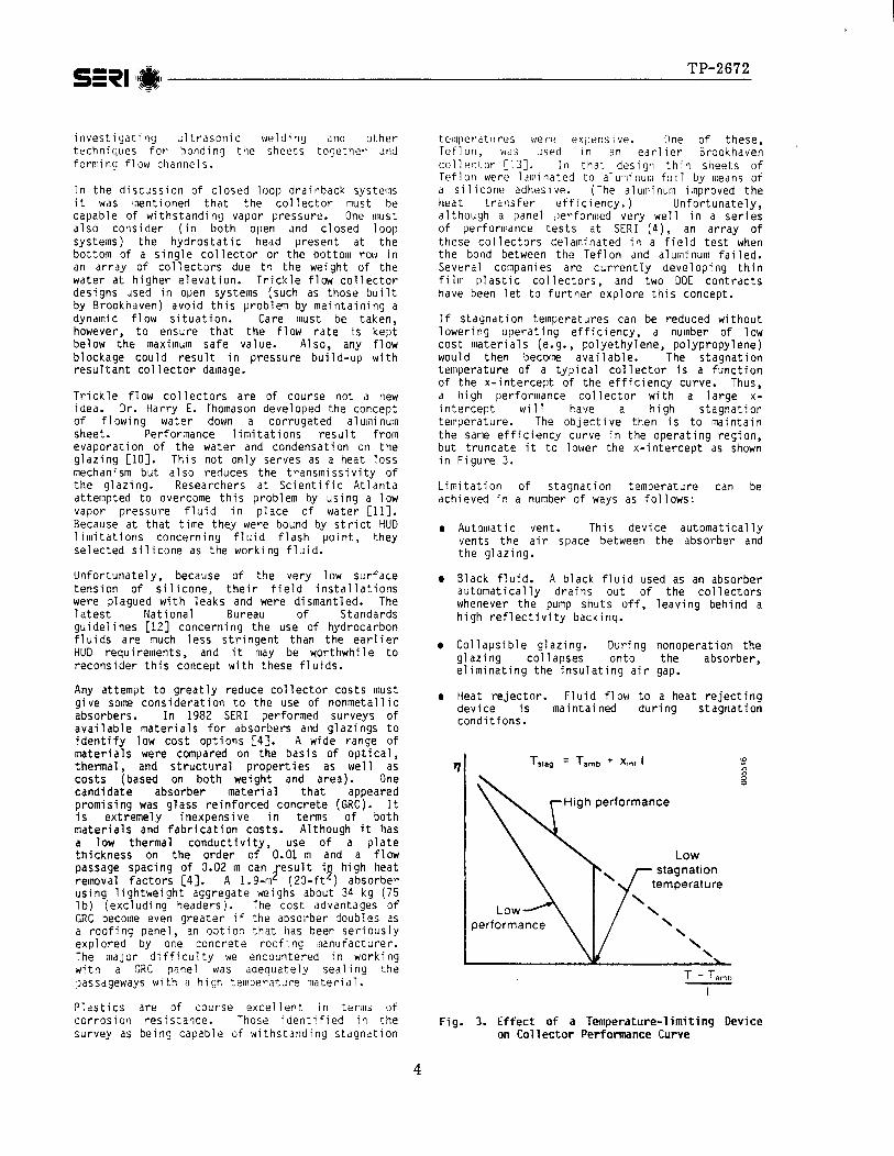
If stagnation temperatures can be reduced without lowering operating efficiency, a number of low cost materials (e.g., polyethylene, polypropylene) would then become available. The stagnation temperature of a typical collector is a function of the x-intercept of the efficiency curve. Thus, a high performance collector with a large x- intercept will have a high stagnation temperature. The objective then is to maintain the same efficiency curve in the operating region, but truncate it to lower the x-intercept as shown in Figure 3,
Limitation of stagndtion temperature can be achieved in a number of ways as follows:
l Automatic vent. This device automatically vents the air space between the absorber and the glazing.
o Black fluid. A black fluid used as an absorber automatically drains out of the collectors whenever the pump shuts off, leaving behind a high reflectivity backinq.
o Collapsible glazing. During nonoperation the glazing collapses onto the absorber, eliminating the insulating air gap.
l Heat rejector. Fluid flow to a heat rejecting device is maintained during stagnation conditions.
r) T stag = Tamb + Knt 1 0
z
High performance
T - Tarn,
Fig. 3. Effect of a Temperature-limiting Device on Collector Performance Curve
4
l Thermochromic glazings or absorbers. These are devices that exhibit large changes in optical properties as a function of temperature.
Each of these devices has its own advantages and disadvantages (which will not be discussed here due to space limitations). Although most have been tried before, none can be definitively ruled out. Their primary application would be with plastic collectors. One example is a rigid, plastic (ethylene-propylene copolymer) collector currently on $54/m2 k
he market that sells to dealers for ($5/ft ). Instantaneous efficiency tests
at SERI indicated that the performance of this collector is limited by a high heat loss coefficient. This is evidently due to the lack of a selective surface, the small amount of back insulation, and an absorber-glazing space that is not sealed from the outside air. Modifying these would improve performance and would also increase the stagnation temperature beyond the limits of the absorber material unless a temperature limiting device could be successfully applied.
Glazings
Although we have focused on absorbers, glazings also offer room for cost reduction. 'J;J;;;;ionably, glass is currently the most
glazing for a flat-plate collector. Plastic glazings can be considerably cheaper, however; and this cost advantage becomes more important after the cost of the absorber has been reduced. Further, collector costs can be reduced if collectors are made larger, thus lowering framing and connection costs on a per-square-foot basis. For this to be done collector weight must be reduced in order that installers can still work without special equipment. Switching from glass to plastic glazings will achieve a significant weight reduction.
Plastic glazings have been improving in terms of UV, thermal, and wind resistance. New polymeric laminates combine the strengths of different materials (e.g., the mechanical strength of one with the UV stability of another) to achieve a superior composite product [4]. Such plastics may well replace glass in the years ahead;
A summary selected Table 1.
Although indicated
of the advantages and disadvantages of ow cost collector concepts is given in
ICS SYSTEMS
our work on drainback systems had that installed cost> can probably be _ -
brought down to a out $25/ftL, this was still short of our $lS/ft 8 cost goal. Since ICS systems eliminate the pump and controller and contain the collector and storage in one unit, it appeared that this design might hold promise for approaching the cost goal.
ICS systems are typically configured as either a single tank in a glazed box with a reflector or multiple tanks in a glazed box butted together as shown in Figs. 4a and 4b. Compared with the single tank design, the multiple tank unit has a lower profile and no reflector losses, but also has a greater area for heat loss. ICS units are plumbed such that whenever a load is drawn, pressurized city water passes through the ICS unit before entering the conventional water heater as shown in Fig. 5. Thus, unlike systems using a collector array, which operates in a recirculating mode, the ICS is a once-through system.
Performance Analysis
A major concern with ICS systems is that because the solar heated water is located outside the
Costlier than plastic; present designs cannot tolerate pressure
Cost of fastening; requires corrosion protection
Requires corrosion protection; not as low in cost as other concepts
Heavy; difficulty sealing
Limited stagnation temperature
5
ideal involute reflector
e tanks together
Fig. 4. Two KS Systems
with
Fig. 5. Typical ICS Plumbing Layout
build'ng, overnight losses degrade performance. Analysis at SERI has indicated that this loss is not a strong function of the ICS volume but is approximately linearly related to the unit's overall loss coefficient, UL. Of course any attempt to lower the loss coefficient (such as addition of another glazing) dlso reduces the optical efficiency, (unless movable nighttime insulation is used).
To analyze the impact of varying U programmed a simple graphical model o +
and vo, we ICS systems
developed at the University of Wisconsin [14]. This model, generated from TRNSYS simulations, assumes a fully mixed tank, negligible change in internal energy of the system over a given month, and a continuous drain of hot water to satisfy the load. Required inputs are monthly average values of incident radiation in the plane of the ICS system, ambient temperature, draw temperature, cold water supply temperature, glazing area, loss coefficient, and Optical efficiency. The model calculates the total energy delivered to the load.
Results generated for Phoenix, Ariz., Denver, Cola., and Madison, Wis., all showed similar effects L-151. Figure 6 shows the combined effect of changes in UL and r) on annual ICS system performance. Note that !he same performance can be obtained for different combinations of UL and �rl l
For example, for the system analyzed, 58 GJ/yr (53 MBtulyr) could be delivered for the following con itions: (0.26 Btu/h-ft 2 'FJ9
T)~ = 0.5, UL = 1.5 W/m2 OC
(0.62 Bju/ho; ft' - F), no = 0.6, UL = 3.5 W/m2 OC
and = 0.7, u = 5.0 W/m (0.88 Btu/h - ft2 yooF). This indicates that performance is quite sensitive to optical efficiency and that reductions in U are not worthwhile unless they can be made without having much effect on qo.
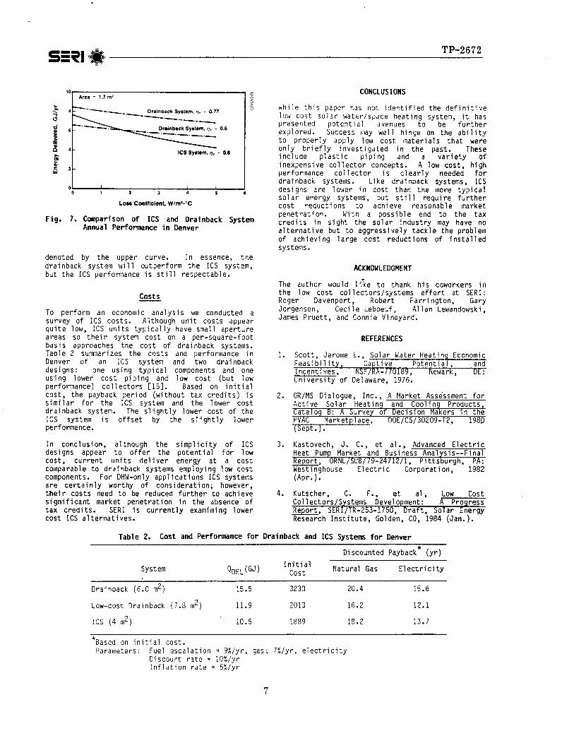
Figure 7 shows the effect of loss coefficient on annual performance for an ICS system and two drainback systems. The ICS system shows greater sensitivity to UL than the drainback system because of the effect of overnight losses. Below a U value of 1.6 W/m2 OC (0.28 Btu/h - ft - OF), the ICS system will outperform a drainback system; however, the collector array in a drainback system will typically have a higher optical efficiency
I Araa = 1.7 ma I
Loss Coefficient, W/m’-%
Fig. 6. Combined Effects on ICS System Annual Performance in Denver (loss coefficient and optical efficiency)
10. Area = 1.7 m2
- a- ---- -2-q- v.
Drainback System, = 0.77
------
4- ICS System, = 4. 0.6
0 I I I 1 I I 0 1 2 3 4 5 6
Loss Coefficient, W/m’-“C
7. Comparison of ICS .and Drainback System Annual Performance in Denver
denoted by the upper curve. In essence, the drainback system will outperform the ICS system, but the ICS performance is still respectable.
costs
To perform an economic analysis we conducted a survey of ICS costs. Although unit costs appear quite low, ICS units typically have small aperture areas so their system cost on a per-square-foot basis approaches the cost of drainback systems. Table 2 summarizes the costs and performance in Denver of an ICS system and two drainback designs: one using typical components and one using lower cost piping and low cost (but low performance) collectors [15]. Based on initial cost, the payback period (without tax credits) is similar for the ICS system and the lower cost drainback system. The slightly lower cost of the ICS system is offset by the slightly lower performance.
In conclusion, although the simplicity of ICS designs appear to offer the potential for low cost, current units deliver energy at a cost comparable to drainback systems employing low cost components. For DHW-only applications ICS systems are certainly worthy of consideration; however, their costs need to be reduced further to achieve significant market penetration in the absence of tax credits. SERI is currently examiming lower cost ICS alternatives.
CONCLUSIONS
While this paper has not identified the definitive low cost solar water/space heating system, it has presented potential avenues to be further explored. Success may well hinge on the ability to properly apply low cost materials that were only briefly investigated in the past. These include plastic piping and a variety of inexpensive collector concepts. A low cost, high performance collector is clearly needed for drainback systems. Like drainback systems, ICS designs are lower in cost than the more typical solar energy systems, but still require further cost reductions to achieve reasonable market penetration. With a possible end to the tax credits in sight the solar industry may have no alternative but to aggressively tackle the problem of achieving large cost reductions of installed systems.
ACKNOWLEDGMENT
The author would liie to thank his coworkers in the low cost collectors/systems effort at SERI: Roger Davenport, Robert Farrington, Gary Jorgensen, Cecile Leboeuf, Allan Lewandowski, James Pruett, and Connie Vineyard.
REFERENCES
1.
2.
3.
4.
Scott, Jerome E., Solar Water Heating Economic Feasibility, Captive Potential, and Incentives, NSF/RA-7/0189 University of Delaware, 1976:
Newark, DE:
OR/MS Dialogue, Inc., A Market Assessment for Active Solar Heating and Cooling Products, Catalog B: A Survey of Decision Makers in the HVAC Marketplace, DOE/CS/30209-T2, 1980 (Sept.).
Kastovech, J. C., et al., Advanced Electric Heat Pump Market and Business Analysis--Final Report, ORNL/SUB//9-24712/l, Pittsburgh, PA: Westinghouse Electric Corporation, 1982 (Apr. 1 l
Kutscher, C. F., et al, Low cost Collectors/Systems Development: A Progress Report, SERI/TR-253-1750, Draft, Solar Energy Research Institute, Golden, CO, 1984 (Jan.).
Table 2. Cost and Performance for Drainback and ICS Systems for Denver
Jorgensen, G. J., ,4 Summary and Assessment of Historical Reliability and Maintain- Data for Active Solar Hot Water and Space Conditioning Systems, SERI/TR-253-2120, Solar Energy Research Institute, Golden, CO, 1984 (Mar.).
ESG, Inc., Survey of System Operational Failure Modes from 122 Residential Solar Water Heater Systems Over a Period of Approximately Two Years, prepared for Solar Energy Research Institute under Subcontract HK-3-03128-1, 1984 (Jan,).
Farrington, R. B., "Evaluation of Pump Efficiencies. and Operating Costs for Solar Domestic Hot Water Systems," presented at the Ninth Annual Conference of the Solar Energy Society of Canada, Inc., Windsor, Ontario, l-5 August 1983.
Farrington, R. B., Failure Testing of Active Solar Energy Components-, SERI/TR-253-2187, Solar tnergy Research Institute, Golden, CO, 1984 (Apr.).
Sims, W. H., "Considerations in the Development of a High Performance Per Unit Cost Solar Collector," Proceedings of the Solar Cooling and Heating Forum, Miami Beach, FL, Dec. 13-15,':976.
10.
11.
12.
13.
14.
15.
Beard, J. T., et al., "Design and Operational Influences on Thermal Performance of Solaris Solar Collector," Engineering for Power, Vol. 100, No. 4, Oct. 1978.
S. V. Shelton, formerly of Scientific Atlanta, personal communication, Oct. 1983.
National Bureau of Standards, "Performance Criteria for Solar Heating and Cooling Systems in Residential Buildings," BSS-147, Washington, D.C., 1982 (Sept.).
Wilhelm, W. S. and J. W. Andrews, The Development of Polymer Film so-5 ' Collectors: A Status Report, BNL 51582 Brookhaven National Laboratory, Brookhaven: NY, 1982 (Aug.).
Zollner, A., S. A. Klein, and W. A. Beckman, "A Performance Prediction Methodology for Inteqral Collection Storaqe Solar Domestic Hot Water Systems," Proceedinqs of the Solar Energy Conference - 1985, Jointly Sponsored by the ASME Solar Engineering Division and the ASES Solar Engineering Division, Knoxville, TN, March, 1985.
Lewandowski, A., C. Leboeuf, and C. F. Kutscher, Solar Space and Hot Water Heating Systems Analysis Task Progress Report, SERIIPR-253-2594, Solar Energy Research Institute, Golden, CO, forthcoming.