48
Certified for ISO9001 and ISO14001 Low Harmonics Regenerative Matrix Converter U1000
| Date post: | 01-Mar-2019 |
| Category: |
Documents |
| Upload: | duonghuong |
| View: | 222 times |
| Download: | 0 times |

Certified forISO9001 andISO14001
Low Harmonics RegenerativeMatrix Converter
U1000
~ MBi-directional AC-ACconversion circuit
Rectifyingcircuit
Powerinvertercircuit
DCsmoothing
circuit
AC DCMotoring energy
Motoring energy
AC
~ M
AC AC
Power Supply
Motor
Power Supply
Motor
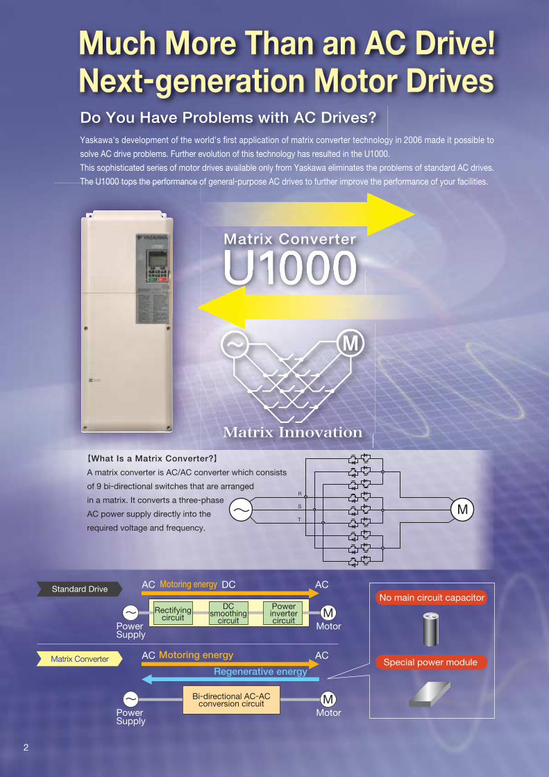
【What Is a Matrix Converter?】
A matrix converter is AC/AC converter which consists
of 9 bi-directional switches that are arranged
in a matrix. It converts a three-phase
AC power supply directly into the
required voltage and frequency.
Matrix Converter
Standard Drive
Regenerative energy
No main circuit capacitor
Special power module
Much More Than an AC Drive!Next-generation Motor DrivesDo You Have Problems with AC Drives?
Matrix Converter
Yaskawa's development of the world's first application of matrix converter technology in 2006 made it possible to
solve AC drive problems. Further evolution of this technology has resulted in the U1000.
This sophisticated series of motor drives available only from Yaskawa eliminates the problems of standard AC drives.
The U1000 tops the performance of general-purpose AC drives to further improve the performance of your facilities.
2
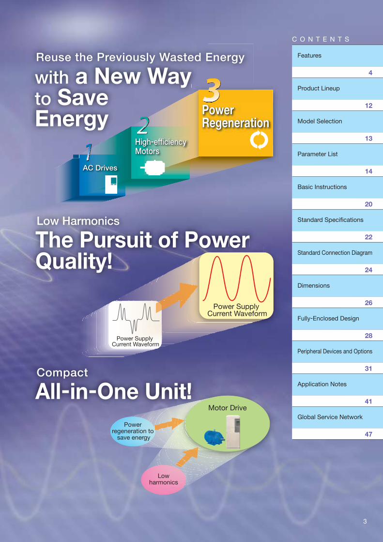
Reuse the Previously Wasted Energy
with a New Wayto Save Energy
High-efficiencyMotorsHigh-efficiencyMotors
AC DrivesAC Drives
Low Harmonics
The Pursuit of Power Quality!
Compact
All-in-One Unit!
Power Supply Current Waveform
Power Supply Current Waveform
Power regeneration to
save energy
Lowharmonics
Motor Drive
PowerRegenerationPowerRegeneration
3
C O N T E N T S
Features
Product Lineup
Model Selection
Parameter List
Basic Instructions
Standard Specifi cations
Standard Connection Diagram
Dimensions
Fully-Enclosed Design
Peripheral Devices and Options
Application Notes
Global Service Network
4
12
13
14
20
22
24
26
28
31
41
47
Previous configuration :10,150kWh
U1000: 4,700kWh
Previous configuration :$2,030
U1000: $9,40
Use analog outputs or communica-tions networks to monitor all sorts of data with easy operations. You'll instantly see the energy that you've saved.
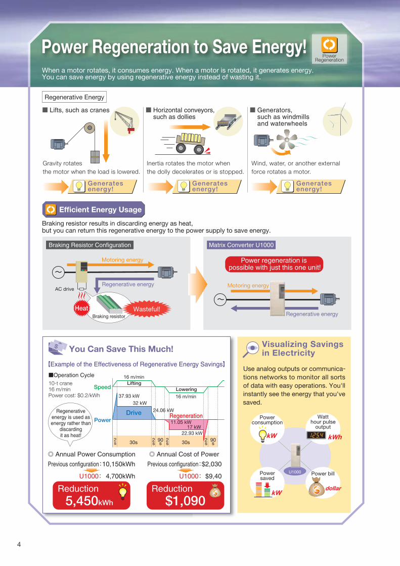
Power Regeneration to Save Energy!When a motor rotates, it consumes energy. When a motor is rotated, it generates energy. You can save energy by using regenerative energy instead of wasting it.
Braking resistor results in discarding energy as heat, but you can return this regenerative energy to the power supply to save energy.
◎ Annual Power Consumption ◎ Annual Cost of Power
Power regeneration is possible with just this one unit!
Generates energy!
Inertia rotates the motor when
the dolly decelerates or is stopped.
Wind, water, or another external
force rotates a motor.
Gravity rotates
the motor when the load is lowered.
Efficient Energy Usage
U1000
Watthour pulse
output
kWh
Powerconsumption
kW
Powersaved
kW
AC drive
Motoring energy
Motoring energyRegenerative energy
Regenerative energy
【Example of the Effectiveness of Regenerative Energy Savings】
10-t crane16 m/minPower cost: $0.2/kWh
Regenerativeenergy is used asenergy rather than
discardingit as heat!
Generates energy!
Reduction
$1,090Reduction
5,450kWh
Visualizing Savings in ElectricityYou Can Save This Much!
Braking Resistor Configuration Matrix Converter U1000
LiftingSpeed
Power
37.93 kW
16 m/min
2s
2s
2s
2s
90s
90s30s 30s
32 kW
24.06 kW
11.05 kW17 kW
22.93 kW
Drive Regeneration
Lowering
16 m/min
gy
PowerRegeneration
Regenerative Energy
Braking resistor
HeatHeat Wasteful!
Generates energy!
Power bill
dollar
$$
Lifts, such as cranes Horizontal conveyors,such as dollies
Generators, such as windmillsand waterwheels
Operation Cycle
4
AC drivewithout reactor
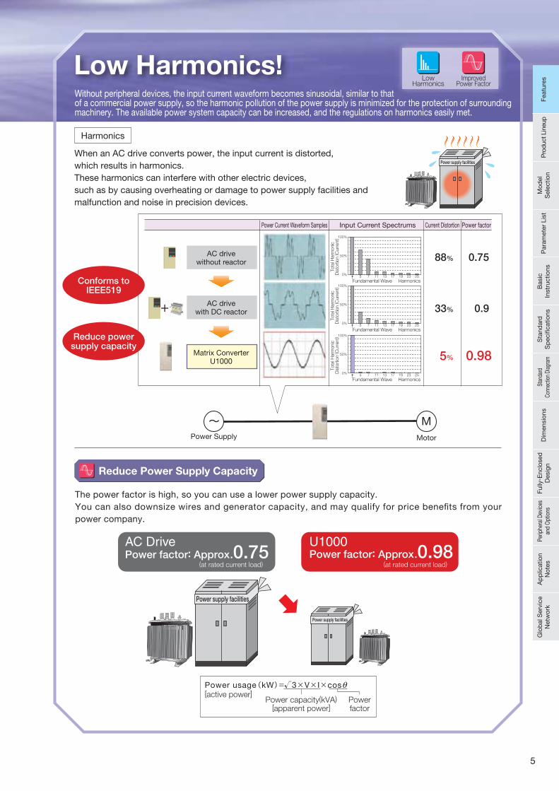
Low Harmonics!Without peripheral devices, the input current waveform becomes sinusoidal, similar to that of a commercial power supply, so the harmonic pollution of the power supply is minimized for the protection of surrounding machinery. The available power system capacity can be increased, and the regulations on harmonics easily met.
Reduce Power Supply Capacity
The power factor is high, so you can use a lower power supply capacity. You can also downsize wires and generator capacity, and may qualify for price benefits from your power company.
Power Supply Motor
Power usage(kW)=√3 × V × I × cos
Power capacity(kVA)[apparent power]
Powerfactor
[active power]θ
0.7588%
0.933%
0.985%
Tota
l Harm
onic
Dis
tort
ion (C
urr
ent)
100%
50%
0%
Fundamental Wave Harmonics5 7 11 13 17 19 23 25
Tota
l Harm
onic
Dis
tort
ion (C
urr
ent)
100%
50%
0%
Fundamental Wave Harmonics5 7 11 13 17 19 23 25
Tota
l Harm
onic
Dis
tort
ion (C
urr
ent)
100%
50%
0%
Fundamental Wave Harmonics5 7 11 13 17 19 23 25
Power Current Waveform Samples Input Current Spectrums Current Distortion Power factor
AC drivewith DC reactor
Matrix ConverterU1000
ImprovedPower Factor
LowHarmonics
AC Drive U1000
Power supply facilities
Power factor: Approx.0.75
Power supply facilities
Power factor: Approx.0.98(at rated current load) (at rated current load)
Harmonics
Conforms toIEEE519
Reduce powersupply capacity
When an AC drive converts power, the input current is distorted, which results in harmonics. These harmonics can interfere with other electric devices, such as by causing overheating or damage to power supply facilities and malfunction and noise in precision devices.
Power supply facilities
5
Feat
ures
Pro
duct
Lin
eup
Mod
el
Sel
ectio
nP
aram
eter
Lis
tB
asic
In
stru
ctio
nsS
tand
ard
S
pec
ifi ca
tions
Stan
dard
Co
nnec
tion
Diag
ram
Dim
ensi
ons
Fully
- Enc
lose
d
Des
ign
Perip
hera
l Dev
ices
an
d O
ptio
nsA
pp
licat
ion
Not
esG
lob
al S
ervi
ce
Net
wor
kFe
atur
es
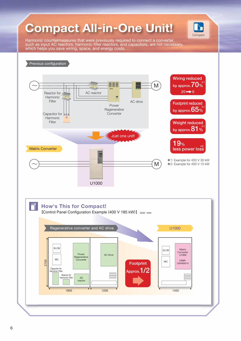
AC drivePower
RegenerativeConverter
Wiring reduced
by approx.70%
Footprint reduced
by approx.65%
Weight reduced
by approx.81%
19%less power loss
AC reactor
U1000
Reactor forHarmonic
Filter
Capacitor forHarmonic
Filter
20 6
*1
*1
*1
*2
*1: Example for 400 V 30 kW
*2: Example for 400 V 15 kW
U1000Regenerative converter and AC drive
Previous configuration
Matrix Converter
Footprint
Approx.1/2
How's This for Compact!【Control Panel Configuration Example (400 V 185 kW)】
Just one unit!
Unit : mm
Compact All-in-One Unit!Harmonic countermeasures that were previously required to connect a converter, such as input AC reactors, harmonic filter reactors, and capacitors, are not necessary, which helps you save wiring, space, and energy costs.
Compact
1200 14501800
2150
ELCB
MC
Capacitor forHarmonic Filter
Reactor forHarmonic Filter AC
reactor
PowerRegenerative
Converter
AC drive
ELCB
MC
MatrixConverter
U1000
CIMR-UA4A0414
6
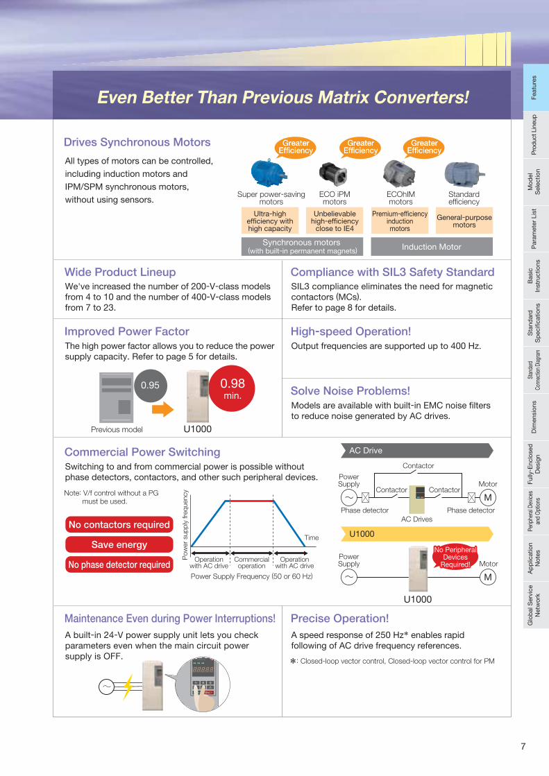
Even Better Than Previous Matrix Converters!
Drives Synchronous Motors
Wide Product Lineup
No contactors required
Save energy
No phase detector requiredOperation
with AC drive
Power Supply Frequency (50 or 60 Hz)
Time
Motor
PowerSupply
PowerSupply
Contactor
Contactor
Phase detector Phase detector
Contactor
AC Drives
Motor
Commercialoperation
Operationwith AC drive
*: Closed-loop vector control, Closed-loop vector control for PM
Pow
er
sup
ply
fre
quency
GreaterEfficiencyGreater
Efficiency
Super power-savingmotors
Ultra-highefficiency withhigh capacity
ECO iPMmotors
Unbelievablehigh-efficiency
close to IE4
ECOhIMmotors
Standardefficiency
General-purposemotors
Synchronous motors (with built-in permanent magnets) Induction Motor
U1000
U1000
0.95 0.98min.
Previous model
All types of motors can be controlled,
including induction motors and
IPM/SPM synchronous motors,
without using sensors.
We've increased the number of 200-V-class models from 4 to 10 and the number of 400-V-class models from 7 to 23.
Compliance with SIL3 Safety StandardSIL3 compliance eliminates the need for magnetic contactors (MCs).Refer to page 8 for details.
Improved Power FactorThe high power factor allows you to reduce the powersupply capacity. Refer to page 5 for details.
High-speed Operation!Output frequencies are supported up to 400 Hz.
Commercial Power SwitchingSwitching to and from commercial power is possible without phase detectors, contactors, and other such peripheral devices.
Solve Noise Problems!Models are available with built-in EMC noise filters to reduce noise generated by AC drives.
Maintenance Even during Power Interruptions!
A built-in 24-V power supply unit lets you check parameters even when the main circuit power supply is OFF.
Precise Operation!
A speed response of 250 Hz* enables rapid following of AC drive frequency references.
Note: V/f control without a PG must be used.
No PeripheralDevices
Required!
No PeripheralDevices
Required!
AC Drive
U1000
Premium-efficiencyinductionmotors
GreaterEfficiencyGreater
EfficiencyGreater
EfficiencyGreater
Efficiency
7
Feat
ures
Pro
duct
Lin
eup
Mod
el
Sel
ectio
nP
aram
eter
Lis
tB
asic
In
stru
ctio
nsS
tand
ard
S
pec
ifi ca
tions
Stan
dard
Co
nnec
tion
Diag
ram
Dim
ensi
ons
Fully
- Enc
lose
d
Des
ign
Perip
hera
l Dev
ices
an
d O
ptio
nsA
pp
licat
ion
Not
esG
lob
al S
ervi
ce
Net
wor
kFe
atur
es
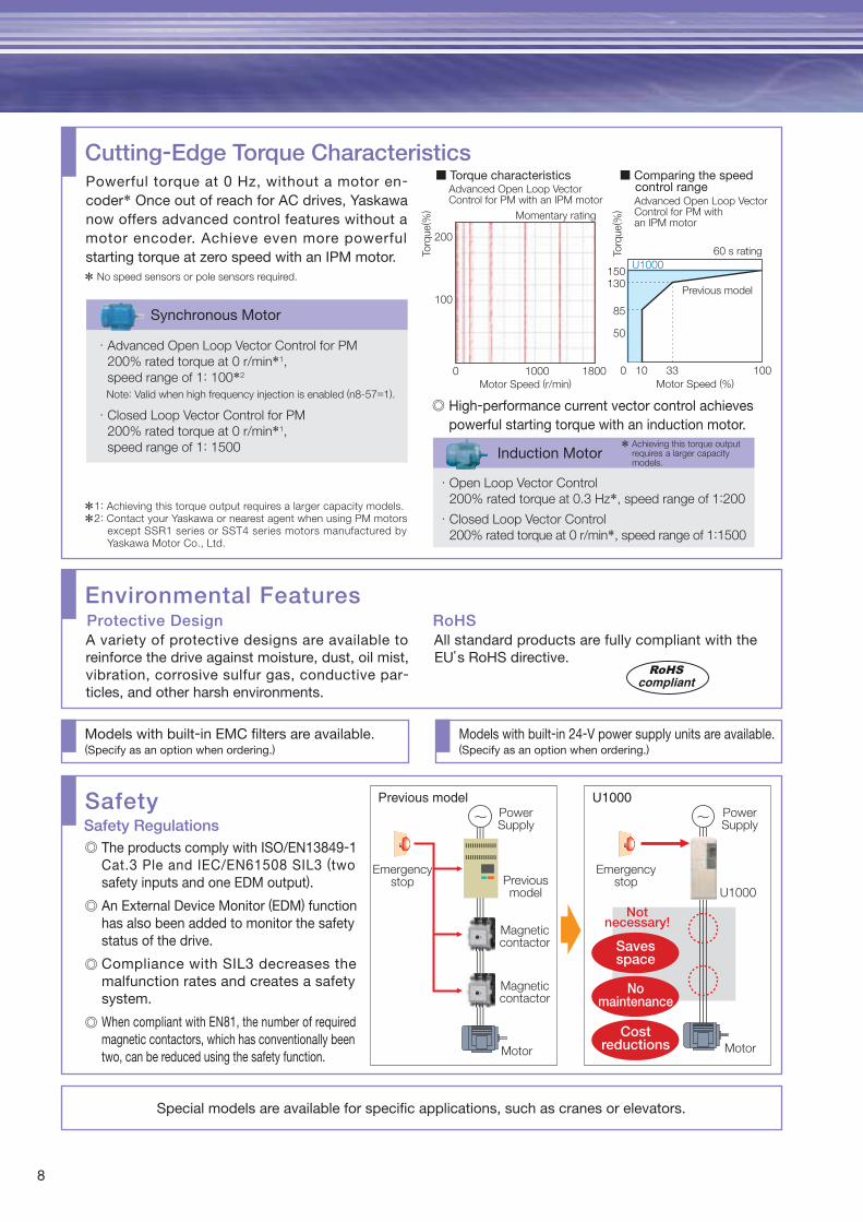
Cutting-Edge Torque CharacteristicsPowerful torque at 0 Hz, without a motor en-coder* Once out of reach for AC drives, Yaskawa now offers advanced control features without a motor encoder. Achieve even more powerful starting torque at zero speed with an IPM motor.
Synchronous Motor
Environmental Features
A variety of protective designs are available to reinforce the drive against moisture, dust, oil mist, vibration, corrosive sulfur gas, conductive par-ticles, and other harsh environments.
Protective Design
Models with built-in EMC filters are available.(Specify as an option when ordering.)
Models with built-in 24-V power supply units are available.(Specify as an option when ordering.)
Special models are available for specific applications, such as cranes or elevators.
All standard products are fully compliant with the EU’s RoHS directive.
RoHS
SafetySafety Regulations
*1: Achieving this torque output requires a larger capacity models.
*2: Contact your Yaskawa or nearest agent when using PM motors except SSR1 series or SST4 series motors manufactured by Yaskawa Motor Co., Ltd.
* No speed sensors or pole sensors required.
Advanced Open Loop Vector Control for PM with an IPM motor Advanced Open Loop Vector
Control for PM with an IPM motor
■ Torque characteristics ■ Comparing the speed control range
Induction Motor * Achieving this torque output requires a larger capacity models.
Motor Speed (r/min)0
100
200
1000 1800
Torq
ue( %
)
Torq
ue( %
)
Momentary rating
150
85
130
50
0 10 33 100
Motor Speed (%)
U1000
Previous model
60 s rating
PowerSupply
Emergencystop
Emergencystop
PowerSupply
U1000Previousmodel
Magneticcontactor
Magneticcontactor
Motor Motor
Savesspace
Nomaintenance
Costreductions
Notnecessary!
Previous model U1000
RoHScompliant
Note: Valid when high frequency injection is enabled (n8-57=1).
Advanced Open Loop Vector Control for PM
200% rated torque at 0 r/min*1,
speed range of 1: 100*2
Closed Loop Vector Control for PM
200% rated torque at 0 r/min*1,
speed range of 1: 1500
High-performance current vector control achieves powerful starting torque with an induction motor.
Open Loop Vector Control
200% rated torque at 0.3 Hz*, speed range of 1:200
Closed Loop Vector Control
200% rated torque at 0 r/min*, speed range of 1:1500
The products comply with ISO/EN13849-1 Cat.3 Ple and IEC/EN61508 SIL3 (two safety inputs and one EDM output).
An External Device Monitor (EDM) function has also been added to monitor the safety status of the drive.
Compliance with SIL3 decreases the malfunction rates and creates a safety system.
When compliant with EN81, the number of required magnetic contactors, which has conventionally been two, can be reduced using the safety function.
8
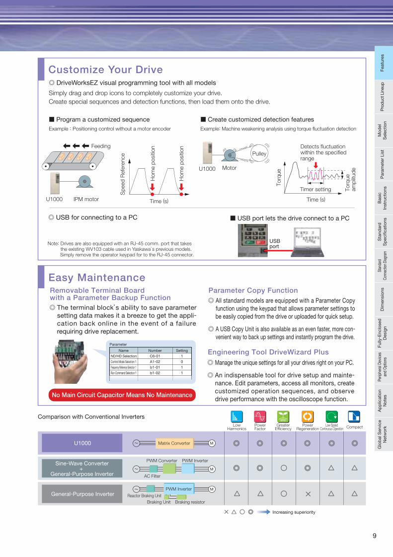
Comparison with Conventional Inverters
The terminal block’s ability to save parameter setting data makes it a breeze to get the appli-cation back online in the event of a failure requiring drive replacement.
Removable Terminal Board with a Parameter Backup Function
Manage the unique settings for all your drives right on your PC.
An indispensable tool for drive setup and mainte-nance. Edit parameters, access all monitors, create customized operation sequences, and observe drive performance with the oscilloscope function.
Engineering Tool DriveWizard Plus
All standard models are equipped with a Parameter Copy function using the keypad that allows parameter settings to be easily copied from the drive or uploaded for quick setup.
A USB Copy Unit is also available as an even faster, more con-venient way to back up settings and instantly program the drive.
Parameter Copy Function
Note: Drives are also equipped with an RJ-45 comm. port that takes the existing WV103 cable used in Yaskawa’s previous models. Simply remove the operator keypad for to the RJ-45 connector.
Example : Positioning control without a motor encoder Example: Machine weakening analysis using torque fluctuation detection
Customize Your Drive
Simply drag and drop icons to completely customize your drive.
Create special sequences and detection functions, then load them onto the drive.
Easy Maintenance
No Main Circuit Capacitor Means No Maintenance
Name
ND/HD Selection
Control Mode Selection 1
Frequency Reference Selection 1
Run Command Selection 1
Number Setting
1
0
1
1
C6-01
A1-02
b1-01
b1-02
Parameter
USBport
Hom
e p
ositio
n
Hom
e p
ositio
n
Sp
eed
Refe
rence
Time (s)IPM motor
Feeding
MotorU1000
Torq
ue
Torq
ue
am
plit
ud
e
Timer setting
Time (s)
Detects fluctuationwithin the specified range
Pulley
Increasing superiority
Sine-Wave Converter+
General-Purpose Inverter
U1000
U1000
General-Purpose Inverter
LowHarmonics
PowerFactor
PWM InverterPWM Converter
AC Filter
GreaterEfficiency
PowerRegeneration
Low-SpeedContinuous Operation Compact
Matrix Converter
Reactor Braking Unit
Braking Unit Braking resistor
PWM Inverter
DriveWorksEZ visual programming tool with all models
USB for connecting to a PC
Program a customized sequence Create customized detection features
USB port lets the drive connect to a PC
9
Feat
ures
Pro
duct
Lin
eup
Mod
el
Sel
ectio
nP
aram
eter
Lis
tB
asic
In
stru
ctio
nsS
tand
ard
S
pec
ifi ca
tions
Stan
dard
Co
nnec
tion
Diag
ram
Dim
ensi
ons
Fully
- Enc
lose
d
Des
ign
Perip
hera
l Dev
ices
an
d O
ptio
nsA
pp
licat
ion
Not
esG
lob
al S
ervi
ce
Net
wor
kFe
atur
es
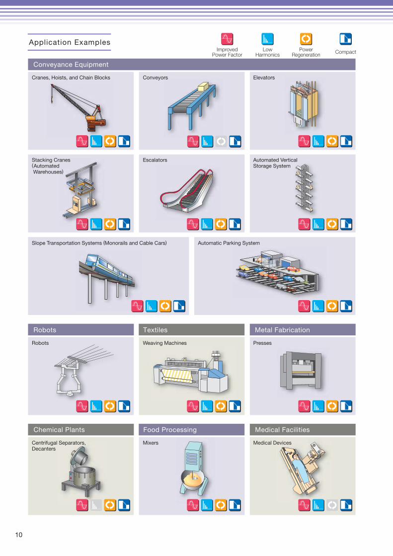
Application Examples
Conveyance Equipment
Robots Textiles Metal Fabrication
Chemical Plants Food Processing Medical Facilities
Cranes, Hoists, and Chain Blocks Conveyors Elevators
Stacking Cranes(Automated Warehouses)
Escalators Automated Vertical Storage System
Slope Transportation Systems (Monorails and Cable Cars) Automatic Parking System
Robots Weaving Machines Presses
Centrifugal Separators, Decanters
Mixers Medical Devices
ImprovedPower Factor
LowHarmonics
PowerRegeneration
Compact
10
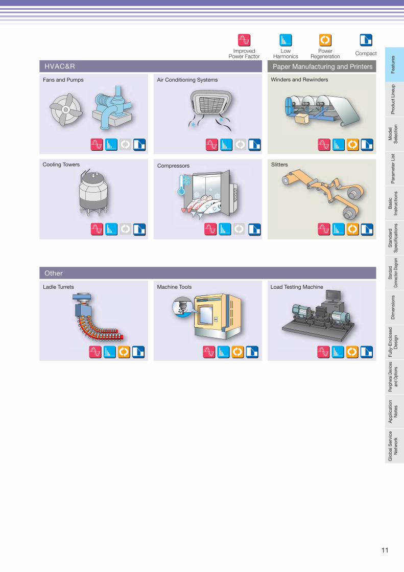
Paper Manufacturing and Printers
Other
Ladle Turrets Machine Tools Load Testing Machine
HVAC&R
Fans and Pumps Air Conditioning Systems
Cooling Towers Compressors
Winders and Rewinders
Slitters
ImprovedPower Factor
LowHarmonics
PowerRegeneration
Compact
11
Feat
ures
Pro
duct
Lin
eup
Mod
el
Sel
ectio
nP
aram
eter
Lis
tB
asic
In
stru
ctio
nsS
tand
ard
S
pec
ifi ca
tions
Stan
dard
Co
nnec
tion
Diag
ram
Dim
ensi
ons
Fully
- Enc
lose
d
Des
ign
Perip
hera
l Dev
ices
an
d O
ptio
nsA
pp
licat
ion
Not
esG
lob
al S
ervi
ce
Net
wor
kFe
atur
es
1212
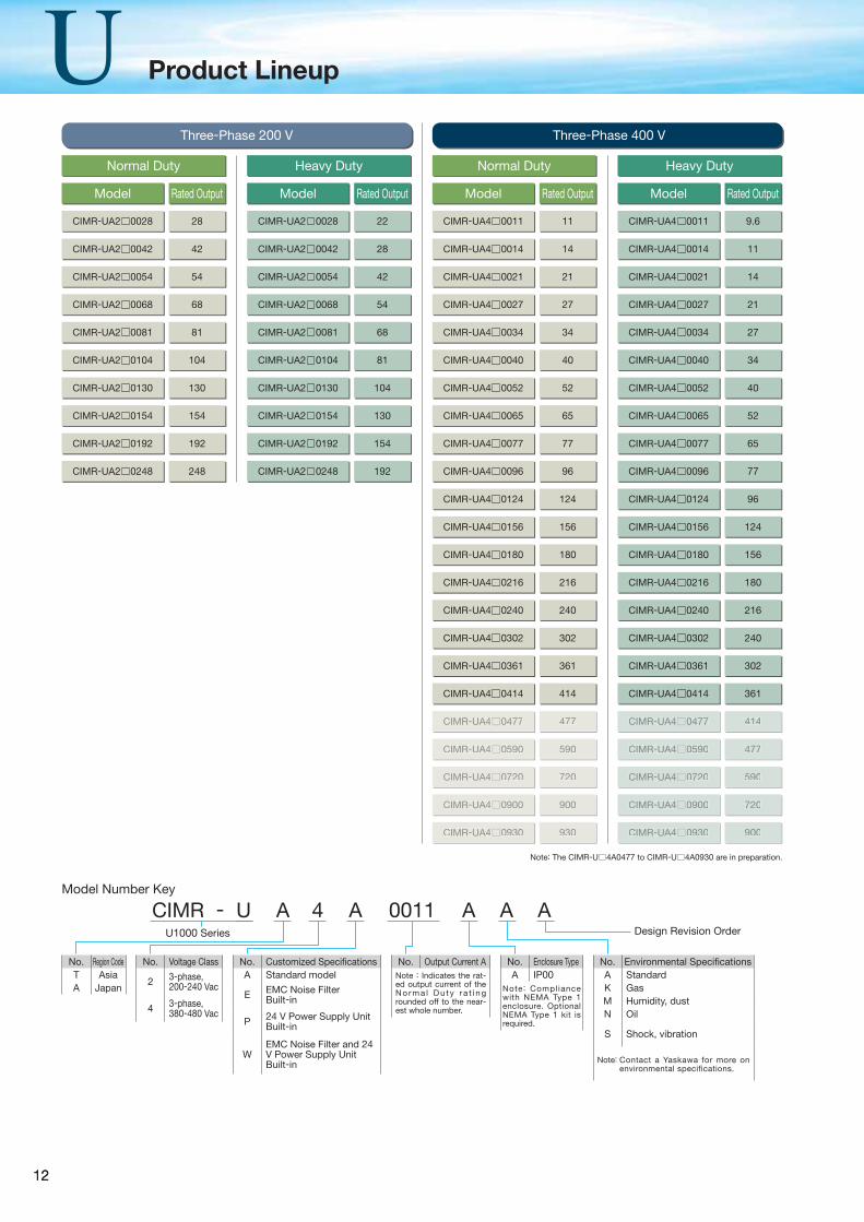
Model Rated Output Model Rated OutputModel Rated Output Model Rated Output
CIMR-UA2 0028 28 CIMR-UA4 0011 11
CIMR-UA4 0124 124
CIMR-UA2 0028 22 CIMR-UA4 0011 9.6
CIMR-UA4 0124 96
CIMR-UA2 0042 42 CIMR-UA4 0014 14
CIMR-UA4 0156 156
CIMR-UA2 0042 28 CIMR-UA4 0014 11
CIMR-UA4 0156 124
CIMR-UA2 0054 54 CIMR-UA4 0021 21
CIMR-UA4 0180 180
CIMR-UA2 0054 42 CIMR-UA4 0021 14
CIMR-UA4 0180 156
CIMR-UA2 0068 68 CIMR-UA4 0027 27
CIMR-UA4 0216 216
CIMR-UA2 0068 54 CIMR-UA4 0027 21
CIMR-UA4 0216 180
CIMR-UA2 0081 81 CIMR-UA4 0034 34
CIMR-UA4 0240 240
CIMR-UA2 0081 68 CIMR-UA4 0034 27
CIMR-UA4 0240 216
CIMR-UA2 0104 104 CIMR-UA4 0040 40
CIMR-UA4 0302 302
CIMR-UA2 0104 81 CIMR-UA4 0040 34
CIMR-UA4 0302 240
CIMR-UA2 0130 130 CIMR-UA4 0052 52
CIMR-UA4 0361 361
CIMR-UA2 0130 104 CIMR-UA4 0052 40
CIMR-UA4 0361 302
CIMR-UA2 0154 154 CIMR-UA4 0065 65
CIMR-UA4 0414 414
CIMR-UA4 0720 720
CIMR-UA2 0154 130 CIMR-UA4 0065 52
CIMR-UA4 0414 361
CIMR-UA4 0720 590
CIMR-UA2 0192 192 CIMR-UA4 0077 77
CIMR-UA4 0477 477
CIMR-UA4 0900 900
CIMR-UA2 0192 154 CIMR-UA4 0077 65
CIMR-UA4 0477 414
CIMR-UA4 0900 720
CIMR-UA2 0248 248 CIMR-UA4 0096 96
CIMR-UA4 0590 590
CIMR-UA4 0930 930
CIMR-UA2 0248 192 CIMR-UA4 0096 77
CIMR-UA4 0590 477
CIMR-UA4 0930 900
Three-Phase 200 V Three-Phase 400 V
Normal DutyNormal Duty Heavy DutyHeavy Duty
Model Number Key
CIMR - U A 4 A 0011 A A AU1000 Series Design Revision Order
No. Region CodeT AsiaA Japan
No. Voltage Class
2 3-phase, 200-240 Vac
4 3-phase, 380-480 Vac
No. Customized Specifi cationsA Standard model
E EMC Noise FilterBuilt-in
P 24 V Power Supply UnitBuilt-in
WEMC Noise Filter and 24 V Power Supply Unit Built-in
No. Output Current ANote : Indicates the rat-ed output current of the N o r m a l D u t y r a t i n g rounded off to the near-est whole number.
No. Enclosure TypeA IP00
Note: Compliance with NEMA Type 1 enclosure. Optional NEMA Type 1 kit is required.
No. Environmental Specifi cationsA StandardK GasM Humidity, dustN Oil
S Shock, vibration
Note: Contact a Yaskawa for more on environmental specifications.
Note: The CIMR-U 4A0477 to CIMR-U 4A0930 are in preparation.
Product Lineup
1313
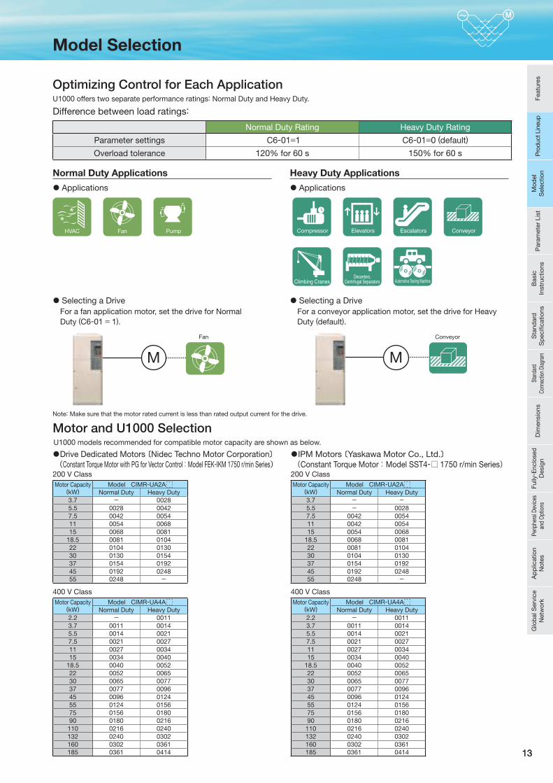
M
Optimizing Control for Each ApplicationU1000 offers two separate performance ratings: Normal Duty and Heavy Duty.
Difference between load ratings:
Normal Duty Rating Heavy Duty Rating
Parameter settings C6-01=1 C6-01=0 (default)
Overload tolerance 120% for 60 s 150% for 60 s
M
Normal Duty Applications Heavy Duty Applications
Applications Applications
Selecting a DriveFor a fan application motor, set the drive for Normal Duty (C6-01 = 1).
Selecting a DriveFor a conveyor application motor, set the drive for Heavy Duty (default).
Fan Conveyor
FanHVAC Pump
Note: Make sure that the motor rated current is less than rated output current for the drive.
Compressor
Automotive Testing MachineClimbing CranesDecanters,
Centrifugal Separators
Elevators Escalators Conveyor
Motor and U1000 SelectionU1000 models recommended for compatible motor capacity are shown as below.
Drive Dedicated Motors 〔Nidec Techno Motor Corporation〕(Constant Torque Motor with PG for Vector Control: Model FEK-IKM 1750 r/min Series)
IPM Motors 〔Yaskawa Motor Co., Ltd.〕(Constant Torque Motor: Model SST4-□ 1750 r/min Series)
Motor Capacity(kW)
Model CIMR-UA2ANormal Duty Heavy Duty
3.7 - 00285.5 0028 00427.5 0042 005411 0054 006815 0068 0081
18.5 0081 010422 0104 013030 0130 015437 0154 019245 0192 024855 0248 -
Motor Capacity(kW)
Model CIMR-UA2ANormal Duty Heavy Duty
3.7 - -5.5 - 00287.5 0042 005411 0042 005415 0054 0068
18.5 0068 008122 0081 010430 0104 013037 0154 019245 0192 024855 0248 -
Motor Capacity(kW)
Model CIMR-UA4ANormal Duty Heavy Duty
2.2 - 00113.7 0011 00145.5 0014 00217.5 0021 002711 0027 003415 0034 0040
18.5 0040 005222 0052 006530 0065 007737 0077 009645 0096 012455 0124 015675 0156 018090 0180 0216110 0216 0240132 0240 0302160 0302 0361185 0361 0414
Motor Capacity(kW)
Model CIMR-UA4ANormal Duty Heavy Duty
2.2 - 00113.7 0011 00145.5 0014 00217.5 0021 002711 0027 003415 0034 0040
18.5 0040 005222 0052 006530 0065 007737 0077 009645 0096 012455 0124 015675 0156 018090 0180 0216110 0216 0240132 0240 0302160 0302 0361185 0361 0414
200 V Class 200 V Class
400 V Class 400 V Class
Feat
ures
Pro
duct
Lin
eup
Mod
el
Sel
ectio
nP
aram
eter
Lis
tB
asic
In
stru
ctio
nsS
tand
ard
S
pec
ifi ca
tions
Stan
dard
Co
nnec
tion
Diag
ram
Dim
ensi
ons
Fully
- Enc
lose
d
Des
ign
Perip
hera
l Dev
ices
an
d O
ptio
nsA
pp
licat
ion
Not
esG
lob
al S
ervi
ce
Net
wor
k
Model Selection
Pro
duct
Lin
eup
Mod
el
Sel
ectio
n
14
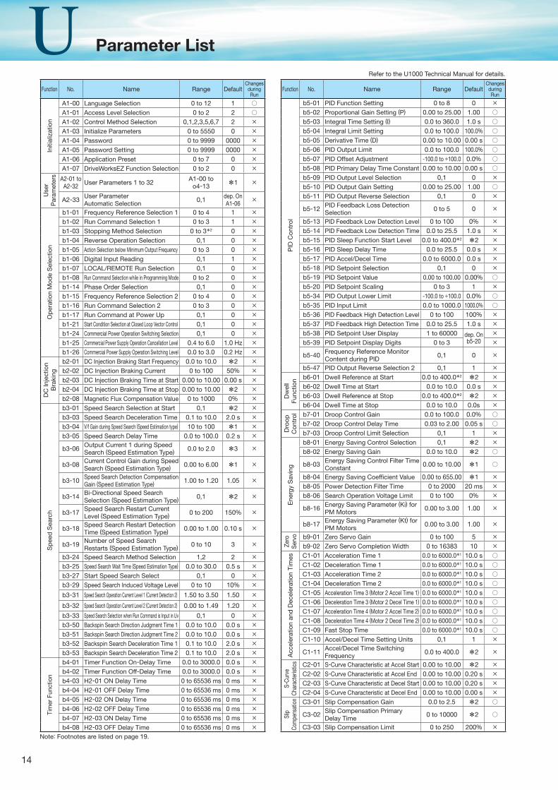
Function No. Name Range DefaultChanges
duringRun
Initi
aliz
atio
n
A1-00 Language Selection 0 to 12 1 ○A1-01 Access Level Selection 0 to 2 2 ○A1-02 Control Method Selection 0,1,2,3,5,6,7 2 ×A1-03 Initialize Parameters 0 to 5550 0 ×A1-04 Password 0 to 9999 0000 ×A1-05 Password Setting 0 to 9999 0000 ×A1-06 Application Preset 0 to 7 0 ×A1-07 DriveWorksEZ Function Selection 0 to 2 0 ×
Use
rP
aram
eter
s A2-01 to A2-32 User Parameters 1 to 32 A1-00 to
o4-13 *1 ×
A2-33 User Parameter Automatic Selection
0,1 dep. On A1-06
×
Op
erat
ion
Mod
e S
elec
tion
b1-01 Frequency Reference Selection 1 0 to 4 1 ×b1-02 Run Command Selection 1 0 to 3 1 ×b1-03 Stopping Method Selection 0 to 3*2 0 ×b1-04 Reverse Operation Selection 0,1 0 ×b1-05 Action Selection below Minimum Output Frequency 0 to 3 0 ×b1-06 Digital Input Reading 0,1 1 ×b1-07 LOCAL/REMOTE Run Selection 0,1 0 ×b1-08 Run Command Selection while in Programming Mode 0 to 2 0 ×b1-14 Phase Order Selection 0,1 0 ×b1-15 Frequency Reference Selection 2 0 to 4 0 ×b1-16 Run Command Selection 2 0 to 3 0 ×b1-17 Run Command at Power Up 0,1 0 ×b1-21 Start Condition Selection at Closed Loop Vector Control 0,1 0 ×b1-24 Commercial Power Operation Switching Selection 0,1 0 ×b1-25 Commercial Power Supply Operation Cancellation Level 0.4 to 6.0 1.0 Hz ×b1-26 Commercial Power Supply Operation Switching Level 0.0 to 3.0 0.2 Hz ×
DC
Inje
ctio
n B
raki
ng
b2-01 DC Injection Braking Start Frequency 0.0 to 10.0 *2 ×b2-02 DC Injection Braking Current 0 to 100 50% ×b2-03 DC Injection Braking Time at Start 0.00 to 10.00 0.00 s ×b2-04 DC Injection Braking Time at Stop 0.00 to 10.00 *2 ×b2-08 Magnetic Flux Compensation Value 0 to 1000 0% ×
Sp
eed
Sea
rch
b3-01 Speed Search Selection at Start 0,1 *2 ×b3-03 Speed Search Deceleration Time 0.1 to 10.0 2.0 s ×b3-04 V/f Gain during Speed Search (Speed Estimation type) 10 to 100 *1 ×b3-05 Speed Search Delay Time 0.0 to 100.0 0.2 s ×
b3-06 Output Current 1 during Speed Search (Speed Estimation Type) 0.0 to 2.0 *3 ×
b3-08 Current Control Gain during Speed Search (Speed Estimation Type) 0.00 to 6.00 *1 ×
b3-10 Speed Search Detection Compensation Gain (Speed Estimation Type) 1.00 to 1.20 1.05 ×
b3-14 Bi-Directional Speed Search Selection (Speed Estimation Type) 0,1 *2 ×
b3-17 Speed Search Restart Current Level (Speed Estimation Type) 0 to 200 150% ×
b3-18 Speed Search Restart Detection Time (Speed Estimation Type) 0.00 to 1.00 0.10 s ×
b3-19 Number of Speed Search Restarts (Speed Estimation Type) 0 to 10 3 ×
b3-24 Speed Search Method Selection 1,2 2 ×b3-25 Speed Search Wait Time (Speed Estimation Type) 0.0 to 30.0 0.5 s ×b3-27 Start Speed Search Select 0,1 0 ×b3-29 Speed Search Induced Voltage Level 0 to 10 10% ×
b3-31 Speed Search Operation Current Level 1 (Current Detection 2) 1.50 to 3.50 1.50 ×
b3-32 Speed Search Operation Current Level 2 (Current Detection 2) 0.00 to 1.49 1.20 ×
b3-33 Speed Search Selection when Run Command is Input in Uv 0,1 0 ×b3-50 Backspin Search Direction Judgment Time 1 0.0 to 10.0 0.0 s ×b3-51 Backspin Search Direction Judgment Time 2 0.0 to 10.0 0.0 s ×b3-52 Backspin Search Deceleration Time 1 0.1 to 10.0 2.0 s ×b3-53 Backspin Search Deceleration Time 2 0.1 to 10.0 2.0 s ×
Tim
er F
unct
ion
b4-01 Timer Function On-Delay Time 0.0 to 3000.0 0.0 s ×b4-02 Timer Function Off-Delay Time 0.0 to 3000.0 0.0 s ×b4-03 H2-01 ON Delay Time 0 to 65536 ms 0 ms ×b4-04 H2-01 OFF Delay Time 0 to 65536 ms 0 ms ×b4-05 H2-02 ON Delay Time 0 to 65536 ms 0 ms ×b4-06 H2-02 OFF Delay Time 0 to 65536 ms 0 ms ×b4-07 H2-03 ON Delay Time 0 to 65536 ms 0 ms ×b4-08 H2-03 OFF Delay Time 0 to 65536 ms 0 ms ×
Function No. Name Range DefaultChanges
duringRun
PID
Con
trol
b5-01 PID Function Setting 0 to 8 0 ×b5-02 Proportional Gain Setting (P) 0.00 to 25.00 1.00 ○b5-03 Integral Time Setting (I) 0.0 to 360.0 1.0 s ○b5-04 Integral Limit Setting 0.0 to 100.0 100.0% ○b5-05 Derivative Time (D) 0.00 to 10.00 0.00 s ○b5-06 PID Output Limit 0.0 to 100.0 100.0% ○b5-07 PID Offset Adjustment -100.0 to +100.0 0.0% ○b5-08 PID Primary Delay Time Constant 0.00 to 10.00 0.00 s ○b5-09 PID Output Level Selection 0,1 0 ×b5-10 PID Output Gain Setting 0.00 to 25.00 1.00 ○b5-11 PID Output Reverse Selection 0,1 0 ×
b5-12 PID Feedback Loss Detection Selection
0 to 5 0 ×
b5-13 PID Feedback Low Detection Level 0 to 100 0% ×b5-14 PID Feedback Low Detection Time 0.0 to 25.5 1.0 s ×b5-15 PID Sleep Function Start Level 0.0 to 400.0*2 *2 ×b5-16 PID Sleep Delay Time 0.0 to 25.5 0.0 s ×b5-17 PID Accel/Decel Time 0.0 to 6000.0 0.0 s ×b5-18 PID Setpoint Selection 0,1 0 ×b5-19 PID Setpoint Value 0.00 to 100.00 0.00% ○b5-20 PID Setpoint Scaling 0 to 3 1 ×b5-34 PID Output Lower Limit -100.0 to +100.0 0.0% ○b5-35 PID Input Limit 0.0 to 1000.0 1000.0% ○b5-36 PID Feedback High Detection Level 0 to 100 100% ×b5-37 PID Feedback High Detection Time 0.0 to 25.5 1.0 s ×b5-38 PID Setpoint User Display 1 to 60000 dep. On
b5-20×
b5-39 PID Setpoint Display Digits 0 to 3 ×
b5-40 Frequency Reference Monitor Content during PID
0,1 0 ×
b5-47 PID Output Reverse Selection 2 0,1 1 ×
Dw
ell
Func
tion b6-01 Dwell Reference at Start 0.0 to 400.0*2 *2 ×
b6-02 Dwell Time at Start 0.0 to 10.0 0.0 s ×b6-03 Dwell Reference at Stop 0.0 to 400.0*2 *2 ×b6-04 Dwell Time at Stop 0.0 to 10.0 0.0s ×
Dro
op
Con
trol b7-01 Droop Control Gain 0.0 to 100.0 0.0% ○
b7-02 Droop Control Delay Time 0.03 to 2.00 0.05 s ○b7-03 Droop Control Limit Selection 0,1 1 ×
Ene
rgy
Sav
ing
b8-01 Energy Saving Control Selection 0,1 *2 ×b8-02 Energy Saving Gain 0.0 to 10.0 *2 ○
b8-03 Energy Saving Control Filter Time Constant
0.00 to 10.00 *1 ○
b8-04 Energy Saving Coeffi cient Value 0.00 to 655.00 *1 ×b8-05 Power Detection Filter Time 0 to 2000 20 ms ×b8-06 Search Operation Voltage Limit 0 to 100 0% ×
b8-16 Energy Saving Parameter (Ki) for PM Motors
0.00 to 3.00 1.00 ×
b8-17 Energy Saving Parameter (Kt) for PM Motors
0.00 to 3.00 1.00 ×
Zero
S
ervo b9-01 Zero Servo Gain 0 to 100 5 ×
b9-02 Zero Servo Completion Width 0 to 16383 10 ×
Acc
eler
atio
n an
d D
ecel
erat
ion
Tim
es C1-01 Acceleration Time 1 0.0 to 6000.0*1 10.0 s ○C1-02 Deceleration Time 1 0.0 to 6000.0*1 10.0 s ○C1-03 Acceleration Time 2 0.0 to 6000.0*1 10.0 s ○C1-04 Deceleration Time 2 0.0 to 6000.0*1 10.0 s ○C1-05 Acceleration Time 3 (Motor 2 Accel Time 1) 0.0 to 6000.0*1 10.0 s ○C1-06 Deceleration Time 3 (Motor 2 Decel Time 1) 0.0 to 6000.0*1 10.0 s ○C1-07 Acceleration Time 4 (Motor 2 Accel Time 2) 0.0 to 6000.0*1 10.0 s ○C1-08 Deceleration Time 4 (Motor 2 Decel Time 2) 0.0 to 6000.0*1 10.0 s ○C1-09 Fast Stop Time 0.0 to 6000.0*1 10.0 s ○C1-10 Accel/Decel Time Setting Units 0,1 1 ×
C1-11 Accel/Decel Time Switching Frequency
0.0 to 400.0 *2 ×
S-Cu
rve
Char
acte
ristic
s C2-01 S-Curve Characteristic at Accel Start 0.00 to 10.00 *2 ×C2-02 S-Curve Characteristic at Accel End 0.00 to 10.00 0.20 s ×C2-03 S-Curve Characteristic at Decel Start 0.00 to 10.00 0.20 s ×C2-04 S-Curve Characteristic at Decel End 0.00 to 10.00 0.00 s ×
Slip
Co
mpe
nsat
ion C3-01 Slip Compensation Gain 0.0 to 2.5 *2 ○
C3-02 Slip Compensation Primary Delay Time
0 to 10000 *2 ○
C3-03 Slip Compensation Limit 0 to 250 200% ×Note: Footnotes are listed on page 19.
Refer to the U1000 Technical Manual for details.
Parameter List
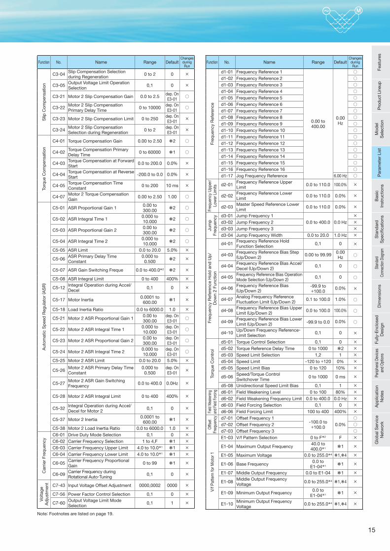
15
Function No. Name Range DefaultChanges
duringRun
Slip
Com
pen
satio
n
C3-04 Slip Compensation Selection during Regeneration
0 to 2 0 ×
C3-05 Output Voltage Limit Operation Selection
0,1 0 ×
C3-21 Motor 2 Slip Compensation Gain 0.0 to 2.5 dep. On E3-01
○
C3-22 Motor 2 Slip Compensation Primary Delay Time
0 to 10000 dep. On E3-01
○
C3-23 Motor 2 Slip Compensation Limit 0 to 250 dep. On E3-01
×
C3-24 Motor 2 Slip Compensation Selection during Regeneration
0 to 2 dep. On E3-01
×
Torq
ue C
omp
ensa
tion
C4-01 Torque Compensation Gain 0.00 to 2.50 *2 ○
C4-02 Torque Compensation Primary Delay Time
0 to 60000 *1 ○
C4-03 Torque Compensation at Forward Start
0.0 to 200.0 0.0% ×
C4-04 Torque Compensation at Reverse Start
-200.0 to 0.0 0.0% ×
C4-05 Torque Compensation Time Constant
0 to 200 10 ms ×
C4-07 Motor 2 Torque Compensation Gain
0.00 to 2.50 1.00 ○
Aut
omat
ic S
pee
d R
egul
ator
( AS
R)
C5-01 ASR Proportional Gain 1 0.00 to 300.00 *2 ○
C5-02 ASR Integral Time 1 0.000 to 10.000 *2 ○
C5-03 ASR Proportional Gain 2 0.00 to 300.00 *2 ○
C5-04 ASR Integral Time 2 0.000 to 10.000 *2 ○
C5-05 ASR Limit 0.0 to 20.0 5.0% ×
C5-06 ASR Primary Delay Time Constant
0.000 to 0.500 *2 ×
C5-07 ASR Gain Switching Freque 0.0 to 400.0*2 *2 ×
C5-08 ASR Integral Limit 0 to 400 400% ×
C5-12 Integral Operation during Accel/Decel
0,1 0 ×
C5-17 Motor Inertia0.0001 to
600.00 *1 ×
C5-18 Load Inertia Ratio 0.0 to 6000.0 1.0 ×
C5-21 Motor 2 ASR Proportional Gain 1 0.00 to 300.00
dep. On E3-01
○
C5-22 Motor 2 ASR Integral Time 1 0.000 to 10.000
dep. On E3-01
○
C5-23 Motor 2 ASR Proportional Gain 2 0.00 to 300.00
dep. On E3-01
○
C5-24 Motor 2 ASR Integral Time 2 0.000 to 10.000
dep. On E3-01
○
C5-25 Motor 2 ASR Limit 0.0 to 20.0 5.0% ×
C5-26 Motor 2 ASR Primary Delay Time Constant
0.000 to 0.500
dep. On E3-01
×
C5-27 Motor 2 ASR Gain SwitchingFrequency
0.0 to 400.0 0.0Hz ×
C5-28 Motor 2 ASR Integral Limit 0 to 400 400% ×
C5-32 Integral Operation during Accel/Decel for Motor 2 0,1 0 ×
C5-37 Motor 2 Inertia0.0001 to
600.00 *1 ×
C5-38 Motor 2 Load Inertia Ratio 0.0 to 6000.0 1.0 ×
Car
rier
Freq
uenc
y
C6-01 Drive Duty Mode Selection 0,1 0 ×C6-02 Carrier Frequency Selection 1 to 4,F *1 ×C6-03 Carrier Frequency Upper Limit 4.0 to 10.0*1 *1 ×C6-04 Carrier Frequency Lower Limit 4.0 to 10.0*1 *1 ×
C6-05 Carrier Frequency Proportional Gain
0 to 99 *1 ×
C6-09 Carrier Frequency during Rotational Auto-Tuning
0,1 0 ×
Volta
ge
Ad
just
men
t
C7-43 Input Voltage Offset Adjustment 0000,0002 0000 ×
C7-56 Power Factor Control Selection 0,1 0 ×
C7-60 Output Voltage Limit Mode Selection
0,1 1 ×
Function No. Name Range DefaultChanges
duringRun
Freq
uenc
y R
efer
ence
d1-01 Frequency Reference 1
0.00 to 400.00
0.00 Hz
○d1-02 Frequency Reference 2 ○d1-03 Frequency Reference 3 ○d1-04 Frequency Reference 4 ○d1-05 Frequency Reference 5 ○d1-06 Frequency Reference 6 ○d1-07 Frequency Reference 7 ○d1-08 Frequency Reference 8 ○d1-09 Frequency Reference 9 ○d1-10 Frequency Reference 10 ○d1-11 Frequency Reference 11 ○d1-12 Frequency Reference 12 ○d1-13 Frequency Reference 13 ○d1-14 Frequency Reference 14 ○d1-15 Frequency Reference 15 ○d1-16 Frequency Reference 16 ○d1-17 Jog Frequency Reference 6.00 Hz ○
Freq
uenc
y U
pper
/Lo
wer
Lim
its d2-01 Frequency Reference Upper Limit
0.0 to 110.0 100.0% ×
d2-02 Frequency Reference Lower Limit
0.0 to 110.0 0.0% ×
d2-03 Master Speed Reference Lower Limit
0.0 to 110.0 0.0% ×Ju
mp
Fr
eque
ncy d3-01 Jump Frequency 1
0.0 to 400.0 0.0 Hz
×d3-02 Jump Frequency 2 ×d3-03 Jump Frequency 3 ×d3-04 Jump Frequency Width 0.0 to 20.0 1.0 Hz ×
Freq
uenc
y R
efer
ence
Hol
d a
nd U
p/
Dow
n 2
Func
tion
d4-01 Frequency Reference Hold Function Selection
0,1 0 ×
d4-03 Frequency Reference Bias Step (Up/Down 2) 0.00 to 99.99 0.00
Hz ○
d4-04 Frequency Reference Bias Accel/Decel (Up/Down 2) 0,1 0 ○
d4-05 Frequency Reference Bias Operation Mode Selection (Up/Down 2) 0,1 0 ○
d4-06 Frequency Reference Bias (Up/Down 2)
-99.9 to +100.0
0.0% ×
d4-07 Analog Frequency Reference Fluctuation Limit (Up/Down 2) 0.1 to 100.0 1.0% ○
d4-08 Frequency Reference Bias Upper Limit (Up/Down 2) 0.0 to 100.0 100.0% ○
d4-09 Frequency Reference Bias Lower Limit (Up/Down 2) -99.9 to 0.0 0.0% ○
d4-10 Up/Down Frequency Reference-Limit Selection
0,1 0 ×
Torq
ue C
ontr
ol
d5-01 Torque Control Selection 0,1 0 ×d5-02 Torque Reference Delay Time 0 to 1000 *2 ×d5-03 Speed Limit Selection 1,2 1 ×d5-04 Speed Limit -120 to +120 0% ×d5-05 Speed Limit Bias 0 to 120 10% ×
d5-06 Speed/Torque Control Switchover Time
0 to 1000 0 ms ×
d5-08 Unidirectional Speed Limit Bias 0,1 1 ×
Field
Wea
kenin
g an
d Fie
ld Fo
rcing d6-01 Field Weakening Level 0 to 100 80% ×
d6-02 Field Weakening Frequency Limit 0.0 to 400.0 0.0 Hz ×d6-03 Field Forcing Selection 0,1 0 ×d6-06 Field Forcing Limit 100 to 400 400% ×
Offs
et
Freq
uenc
y d7-01 Offset Frequency 1-100.0 to +100.0
0.0%
○d7-02 Offset Frequency 2 ○d7-03 Offset Frequency 3 ○
V/f P
atte
rn fo
r Mot
or 1
E1-03 V/f Pattern Selection 0 to F*2 F ×
E1-04 Maximum Output Frequency40.0 to 400.0*1 *1 ×
E1-05 Maximum Voltage 0.0 to 255.0*4 *1,*4 ×
E1-06 Base Frequency0.0 to
E1-04*1 *1 ×
E1-07 Middle Output Frequency 0.0 to E1-04 *1 ×
E1-08 Middle Output Frequency Voltage
0.0 to 255.0*4 *1,*4 ×
E1-09 Minimum Output Frequency0.0 to
E1-04*1 *1 ×
E1-10 Minimum Output Frequency Voltage
0.0 to 255.0*4 *1,*4 ×
Note: Footnotes are listed on page 19.
Feat
ures
Pro
duct
Lin
eup
Mod
el
Sel
ectio
nP
aram
eter
Lis
tB
asic
In
stru
ctio
nsS
tand
ard
S
pec
ifi ca
tions
Stan
dard
Co
nnec
tion
Diag
ram
Dim
ensi
ons
Fully
- Enc
lose
d
Des
ign
Perip
hera
l Dev
ices
an
d O
ptio
nsA
pp
licat
ion
Not
esG
lob
al S
ervi
ce
Net
wor
kP
aram
eter
Lis
t
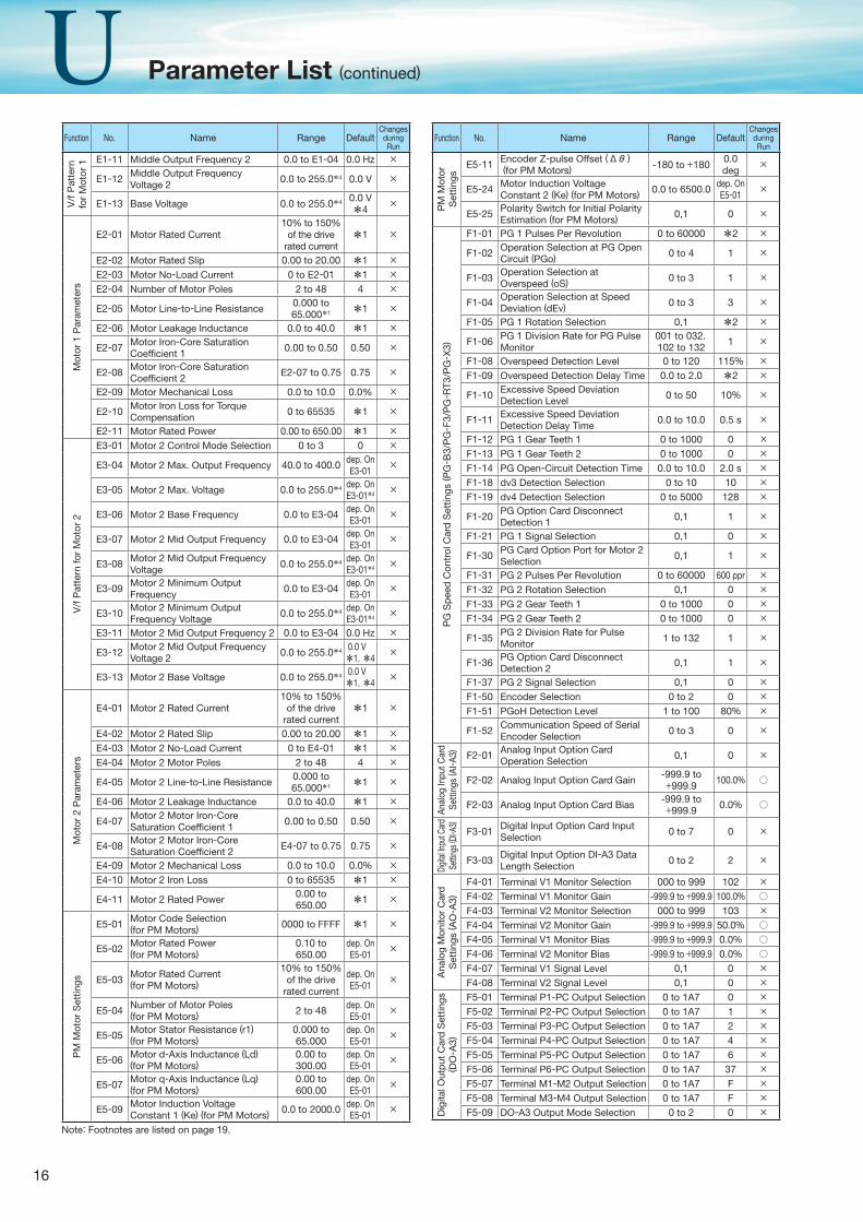
16
Function No. Name Range DefaultChanges
duringRun
V/f
Pat
tern
fo
r M
otor
1 E1-11 Middle Output Frequency 2 0.0 to E1-04 0.0 Hz ×
E1-12 Middle Output Frequency Voltage 2 0.0 to 255.0*4 0.0 V ×
E1-13 Base Voltage 0.0 to 255.0*4 0.0 V
*4×
Mot
or 1
Par
amet
ers
E2-01 Motor Rated Current10% to 150%
of the drive rated current
*1 ×
E2-02 Motor Rated Slip 0.00 to 20.00 *1 ×E2-03 Motor No-Load Current 0 to E2-01 *1 ×E2-04 Number of Motor Poles 2 to 48 4 ×
E2-05 Motor Line-to-Line Resistance0.000 to 65.000*1 *1 ×
E2-06 Motor Leakage Inductance 0.0 to 40.0 *1 ×
E2-07 Motor Iron-Core Saturation Coefficient 1 0.00 to 0.50 0.50 ×
E2-08 Motor Iron-Core Saturation Coefficient 2 E2-07 to 0.75 0.75 ×
E2-09 Motor Mechanical Loss 0.0 to 10.0 0.0% ×
E2-10 Motor Iron Loss for Torque Compensation
0 to 65535 *1 ×
E2-11 Motor Rated Power 0.00 to 650.00 *1 ×
V/f
Pat
tern
for
Mot
or 2
E3-01 Motor 2 Control Mode Selection 0 to 3 0 ×
E3-04 Motor 2 Max. Output Frequency 40.0 to 400.0 dep. On E3-01
×
E3-05 Motor 2 Max. Voltage 0.0 to 255.0*4 dep. On E3-01*4 ×
E3-06 Motor 2 Base Frequency 0.0 to E3-04 dep. On E3-01
×
E3-07 Motor 2 Mid Output Frequency 0.0 to E3-04 dep. On E3-01
×
E3-08 Motor 2 Mid Output Frequency Voltage
0.0 to 255.0*4 dep. On E3-01*4 ×
E3-09 Motor 2 Minimum Output Frequency
0.0 to E3-04 dep. On E3-01
×
E3-10 Motor 2 Minimum Output Frequency Voltage
0.0 to 255.0*4 dep. On E3-01*4 ×
E3-11 Motor 2 Mid Output Frequency 2 0.0 to E3-04 0.0 Hz ×
E3-12 Motor 2 Mid Output Frequency Voltage 2 0.0 to 255.0*4 0.0 V
*1,*4×
E3-13 Motor 2 Base Voltage 0.0 to 255.0*4 0.0 V
*1,*4×
Mot
or 2
Par
amet
ers
E4-01 Motor 2 Rated Current10% to 150%
of the drive rated current
*1 ×
E4-02 Motor 2 Rated Slip 0.00 to 20.00 *1 ×E4-03 Motor 2 No-Load Current 0 to E4-01 *1 ×E4-04 Motor 2 Motor Poles 2 to 48 4 ×
E4-05 Motor 2 Line-to-Line Resistance0.000 to 65.000*1 *1 ×
E4-06 Motor 2 Leakage Inductance 0.0 to 40.0 *1 ×
E4-07 Motor 2 Motor Iron-Core Saturation Coefficient 1 0.00 to 0.50 0.50 ×
E4-08 Motor 2 Motor Iron-Core Saturation Coefficient 2 E4-07 to 0.75 0.75 ×
E4-09 Motor 2 Mechanical Loss 0.0 to 10.0 0.0% ×E4-10 Motor 2 Iron Loss 0 to 65535 *1 ×
E4-11 Motor 2 Rated Power0.00 to 650.00 *1 ×
PM
Mot
or S
ettin
gs
E5-01 Motor Code Selection (for PM Motors) 0000 to FFFF *1 ×
E5-02 Motor Rated Power (for PM Motors)
0.10 to 650.00
dep. On E5-01
×
E5-03 Motor Rated Current (for PM Motors)
10% to 150% of the drive
rated current
dep. On E5-01
×
E5-04 Number of Motor Poles (for PM Motors) 2 to 48 dep. On
E5-01×
E5-05 Motor Stator Resistance (r1) (for PM Motors)
0.000 to 65.000
dep. On E5-01
×
E5-06 Motor d-Axis Inductance (Ld) (for PM Motors)
0.00 to 300.00
dep. On E5-01
×
E5-07 Motor q-Axis Inductance (Lq) (for PM Motors)
0.00 to 600.00
dep. On E5-01
×
E5-09 Motor Induction Voltage Constant 1 (Ke) (for PM Motors) 0.0 to 2000.0 dep. On
E5-01×
Function No. Name Range DefaultChanges
duringRun
PM
Mot
or
Set
tings
E5-11 Encoder Z-pulse Offset (Δθ ) (for PM Motors) -180 to +180
0.0 deg
×
E5-24 Motor Induction Voltage Constant 2 (Ke) (for PM Motors) 0.0 to 6500.0 dep. On
E5-01×
E5-25 Polarity Switch for Initial Polarity Estimation (for PM Motors) 0,1 0 ×
PG
Sp
eed
Con
trol
Car
d S
ettin
gs ( P
G- B
3/P
G- F
3/P
G- R
T3/P
G- X
3)
F1-01 PG 1 Pulses Per Revolution 0 to 60000 *2 ×
F1-02 Operation Selection at PG Open Circuit (PGo) 0 to 4 1 ×
F1-03 Operation Selection at Overspeed (oS) 0 to 3 1 ×
F1-04 Operation Selection at Speed Deviation (dEv) 0 to 3 3 ×
F1-05 PG 1 Rotation Selection 0,1 *2 ×
F1-06 PG 1 Division Rate for PG Pulse Monitor
001 to 032,102 to 132 1 ×
F1-08 Overspeed Detection Level 0 to 120 115% ×F1-09 Overspeed Detection Delay Time 0.0 to 2.0 *2 ×
F1-10 Excessive Speed Deviation Detection Level
0 to 50 10% ×
F1-11 Excessive Speed Deviation Detection Delay Time
0.0 to 10.0 0.5 s ×
F1-12 PG 1 Gear Teeth 1 0 to 1000 0 ×F1-13 PG 1 Gear Teeth 2 0 to 1000 0 ×F1-14 PG Open-Circuit Detection Time 0.0 to 10.0 2.0 s ×F1-18 dv3 Detection Selection 0 to 10 10 ×F1-19 dv4 Detection Selection 0 to 5000 128 ×
F1-20 PG Option Card Disconnect Detection 1 0,1 1 ×
F1-21 PG 1 Signal Selection 0,1 0 ×
F1-30 PG Card Option Port for Motor 2 Selection
0,1 1 ×
F1-31 PG 2 Pulses Per Revolution 0 to 60000 600 ppr ×F1-32 PG 2 Rotation Selection 0,1 0 ×F1-33 PG 2 Gear Teeth 1 0 to 1000 0 ×F1-34 PG 2 Gear Teeth 2 0 to 1000 0 ×
F1-35 PG 2 Division Rate for Pulse Monitor
1 to 132 1 ×
F1-36 PG Option Card Disconnect Detection 2 0,1 1 ×
F1-37 PG 2 Signal Selection 0,1 0 ×F1-50 Encoder Selection 0 to 2 0 ×F1-51 PGoH Detection Level 1 to 100 80% ×
F1-52 Communication Speed of Serial Encoder Selection
0 to 3 0 ×
Anal
og In
put C
ard
Setti
ngs
( AI- A
3) F2-01 Analog Input Option Card Operation Selection
0,1 0 ×
F2-02 Analog Input Option Card Gain -999.9 to +999.9 100.0% ○
F2-03 Analog Input Option Card Bias-999.9 to +999.9 0.0% ○
Digit
al Inp
ut C
ard
Setti
ngs (
DI- A
3)
F3-01 Digital Input Option Card Input Selection
0 to 7 0 ×
F3-03 Digital Input Option DI-A3 Data Length Selection
0 to 2 2 ×
Ana
log
Mon
itor
Car
d
Set
tings
( AO
- A3)
F4-01 Terminal V1 Monitor Selection 000 to 999 102 ×F4-02 Terminal V1 Monitor Gain -999.9 to +999.9 100.0% ○F4-03 Terminal V2 Monitor Selection 000 to 999 103 ×F4-04 Terminal V2 Monitor Gain -999.9 to +999.9 50.0% ○F4-05 Terminal V1 Monitor Bias -999.9 to +999.9 0.0% ○F4-06 Terminal V2 Monitor Bias -999.9 to +999.9 0.0% ○F4-07 Terminal V1 Signal Level 0,1 0 ×F4-08 Terminal V2 Signal Level 0,1 0 ×
Dig
ital O
utp
ut C
ard
Set
tings
( D
O- A
3)
F5-01 Terminal P1-PC Output Selection 0 to 1A7 0 ×F5-02 Terminal P2-PC Output Selection 0 to 1A7 1 ×F5-03 Terminal P3-PC Output Selection 0 to 1A7 2 ×F5-04 Terminal P4-PC Output Selection 0 to 1A7 4 ×F5-05 Terminal P5-PC Output Selection 0 to 1A7 6 ×F5-06 Terminal P6-PC Output Selection 0 to 1A7 37 ×F5-07 Terminal M1-M2 Output Selection 0 to 1A7 F ×F5-08 Terminal M3-M4 Output Selection 0 to 1A7 F ×F5-09 DO-A3 Output Mode Selection 0 to 2 0 ×
Note: Footnotes are listed on page 19.
Parameter List (continued)
17
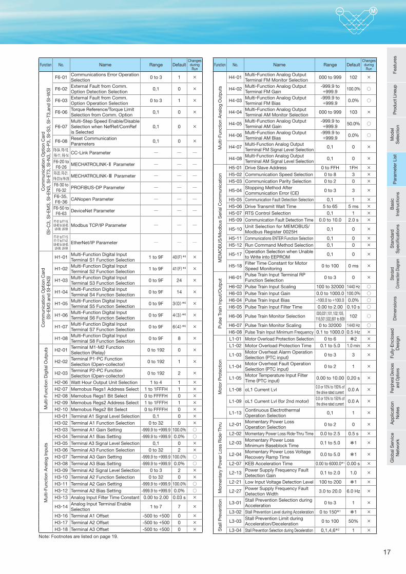
Note: Footnotes are listed on page 19.
Function No. Name Range DefaultChanges
duringRun
Com
mun
icat
ion
Op
tion
Car
d
( SI-
C3,
SI-
EM
3, S
I-E
N3,
SI-
ET3
, SI-
N3,
SI-
P3,
SI-
S3,
SI-
T3,a
nd S
I-W
3)
F6-01 Communications Error Operation Selection
0 to 3 1 ×
F6-02 External Fault from Comm. Option Detection Selection
0,1 0 ×
F6-03 External Fault from Comm. Option Operation Selection
0 to 3 1 ×
F6-06 Torque Reference/Torque Limit Selection from Comm. Option
0,1 0 ×
F6-07Multi-Step Speed Enable/Disable Selection when NefRef/ComRef is Selected
0,1 0 ×
F6-08 Reset Communication Parameters
0,1 0 ×
F6-04,F6-10,F6-11,F6-14 CC-Link Parameter ─ ─ ─
F6-20 to F6-26 MECHATROLINK- Parameter ─ ─ ─
F6-20,F6-21,F6-23 to F6-26 MECHATROLINK- Parameter ─ ─ ─
F6-30 to F6-32 PROFIBUS-DP Parameter ─ ─ ─
F6-35,F6-36 CANopen Parameter ─ ─ ─
F6-50 to F6-63 DeviceNet Parameter ─ ─ ─
F7-01 to F7-16,U6-80 to U6-93,
U6-98,U6-99Modbus TCP/IP Parameter ─ ─ ─
F7-01 to F7-15,F7-17 to F7-42,U6-80 to U6-93,
U6-98,U6-99EtherNet/IP Parameter ─ ─ ─
Com
mun
icat
ion
Op
tion
Car
d( S
I-E
M3
and
SI-
EN
3)
H1-01 Multi-Function Digital Input Terminal S1 Function Selection
1 to 9F 40(F)*6 ×
H1-02 Multi-Function Digital Input Terminal S2 Function Selection
1 to 9F 41(F)*6 ×
H1-03 Multi-Function Digital Input Terminal S3 Function Selection
0 to 9F 24 ×
H1-04 Multi-Function Digital Input Terminal S4 Function Selection
0 to 9F 14 ×
H1-05 Multi-Function Digital Input Terminal S5 Function Selection
0 to 9F 3(0)*6 ×
H1-06 Multi-Function Digital Input Terminal S6 Function Selection
0 to 9F 4(3)*6 ×
H1-07 Multi-Function Digital Input Terminal S7 Function Selection
0 to 9F 6(4)*6 ×
H1-08 Multi-Function Digital Input Terminal S8 Function Selection
0 to 9F 8 ×
Mul
ti-Fu
nctio
n D
igita
l Out
put
s H2-01 Terminal M1-M2 Function Selection (Relay) 0 to 192 0 ×
H2-02 Terminal P1-PC Function Selection (Open-collector)
0 to 192 1 ×
H2-03 Terminal P2-PC Function Selection (Open-collector)
0 to 192 2 ×
H2-06 Watt Hour Output Unit Selection 1 to 4 1 ×H2-07 Memobus Regs1 Address Select 1 to 1FFFH 1 ×H2-08 Memobus Regs1 Bit Select 0 to FFFFH 0 ×H2-09 Memobus Regs2 Address Select 1 to 1FFFH 1 ×H2-10 Memobus Regs2 Bit Select 0 to FFFFH 0 ×
Mul
ti-Fu
nctio
n A
nalo
g In
put
s
H3-01 Terminal A1 Signal Level Selection 0,1 0 ×H3-02 Terminal A1 Function Selection 0 to 32 0 ×H3-03 Terminal A1 Gain Setting -999.9 to +999.9 100.0% ○H3-04 Terminal A1 Bias Setting -999.9 to +999.9 0.0% ○H3-05 Terminal A3 Signal Level Selection 0,1 0 ×H3-06 Terminal A3 Function Selection 0 to 32 2 ×H3-07 Terminal A3 Gain Setting -999.9 to +999.9 100.0% ○H3-08 Terminal A3 Bias Setting -999.9 to +999.9 0.0% ○H3-09 Terminal A2 Signal Level Selection 0 to 3 2 ×H3-10 Terminal A2 Function Selection 0 to 32 0 ×H3-11 Terminal A2 Gain Setting -999.9 to +999.9 100.0% ○H3-12 Terminal A2 Bias Setting -999.9 to +999.9 0.0% ○H3-13 Analog Input Filter Time Constant 0.00 to 2.00 0.03 s ×
H3-14 Analog Input Terminal Enable Selection
1 to 7 7 ×
H3-16 Terminal A1 Offset -500 to +500 0 ×H3-17 Terminal A2 Offset -500 to +500 0 ×H3-18 Terminal A3 Offset -500 to +500 0 ×
Function No. Name Range DefaultChanges
duringRun
Mul
ti-Fu
nctio
n A
nalo
g O
utp
uts
H4-01 Multi-Function Analog Output Terminal FM Monitor Selection
000 to 999 102 ×
H4-02 Multi-Function Analog Output Terminal FM Gain
-999.9 to +999.9 100.0% ○
H4-03 Multi-Function Analog Output Terminal FM Bias
-999.9 to +999.9 0.0% ○
H4-04 Multi-Function Analog Output Terminal AM Monitor Selection
000 to 999 103 ×
H4-05 Multi-Function Analog Output Terminal AM Gain
-999.9 to +999.9 50.0% ○
H4-06 Multi-Function Analog Output Terminal AM Bias
-999.9 to +999.9 0.0% ○
H4-07 Multi-Function Analog Output Terminal FM Signal Level Selection
0,1 0 ×
H4-08 Multi-Function Analog Output Terminal AM Signal Level Selection
0,1 0 ×
ME
MO
BU
S/M
odb
us S
eria
l Com
mun
icat
ion
H5-01 Drive Slave Address 0 to FFH 1FH ×H5-02 Communication Speed Selection 0 to 8 3 ×H5-03 Communication Parity Selection 0 to 2 0 ×
H5-04 Stopping Method After Communication Error (CE) 0 to 3 3 ×
H5-05 Communication Fault Detection Selection 0,1 1 ×H5-06 Drive Transmit Wait Time 5 to 65 5 ms ×H5-07 RTS Control Selection 0,1 1 ×H5-09 Communication Fault Detection Time 0.0 to 10.0 2.0 s ×
H5-10 Unit Selection for MEMOBUS/Modbus Register 0025H
0,1 0 ×
H5-11 Communications ENTER Function Selection 0,1 0 ×H5-12 Run Command Method Selection 0,1 0 ×
H5-17 Operation Selection when Unable to Write into EEPROM
0,1 0 ×
H5-18 Filter Time Constant for Motor Speed Monitoring
0 to 100 0 ms ×
Pul
se T
rain
Inp
ut/O
utp
ut
H6-01 Pulse Train Input Terminal RP Function Selection
0 to 3 0 ×
H6-02 Pulse Train Input Scaling 100 to 32000 1440 Hz ○H6-03 Pulse Train Input Gain 0.0 to 1000.0 100.0% ○H6-04 Pulse Train Input Bias -100.0 to +100.0 0.0% ○H6-05 Pulse Train Input Filter Time 0.00 to 2.00 0.10 s ○
H6-06 Pulse Train Monitor Selection000,031,101,102,105,116,501,502,801 to 809 102 ○
H6-07 Pulse Train Monitor Scaling 0 to 32000 1440 Hz ○H6-08 Pulse Train Input Minimum Frequency 0.1 to 1000.0 0.5 Hz ×
Mot
or P
rote
ctio
n
L1-01 Motor Overload Protection Selection 0 to 6 *2 ×L1-02 Motor Overload Protection Time 0.1 to 5.0 1.0 min ×
L1-03 Motor Overheat Alarm Operation Selection (PTC input)
0 to 3 3 ×
L1-04 Motor Overheat Fault Operation Selection (PTC input)
0 to 2 1 ×
L1-05 Motor Temperature Input Filter Time (PTC input)
0.00 to 10.00 0.20 s ×
L1-08 oL1 Current Lvl0.0 or 10% to 150% of the drive rated current
0.0 A ×
L1-09 oL1 Current Lvl (for 2nd motor)0.0 or 10% to 150% of the drive rated current
0.0 A ×
L1-13 Continuous Electrothermal Operation Selection
0,1 1 ×
Mom
enta
ry P
ower
Los
s R
ide-
Thru L2-01 Momentary Power Loss
Operation Selection0 to 2 0 ×
L2-02 Momentary Power Loss Ride-Thru Time 0.0 to 2.5 0.5 s ×
L2-03 Momentary Power Loss Minimum Baseblock Time
0.1 to 5.0 *1 ×
L2-04 Momentary Power Loss Voltage Recovery Ramp Time
0.0 to 5.0 *1 ×
L2-07 KEB Acceleration Time 0.00 to 6000.0*1 0.00 s ×
L2-13 Power Supply Frequency Fault Detection Gain
0.1 to 2.0 1.0 ×
L2-21 Low Input Voltage Detection Level 100 to 200 *1 ×
L2-27 Power Supply Frequency Fault Detection Width
3.0 to 20.0 6.0 Hz ×
Sta
ll P
reve
ntio
n L3-01 Stall Prevention Selection during Acceleration
0 to 3 1 ×
L3-02 Stall Prevention Level during Acceleration 0 to 150*1 *1 ×
L3-03 Stall Prevention Limit during Acceleration/Deceleration
0 to 100 50% ×
L3-04 Stall Prevention Selection during Deceleration 0,1,4,6*2 1 ×
Feat
ures
Pro
duct
Lin
eup
Mod
el
Sel
ectio
nP
aram
eter
Lis
tB
asic
In
stru
ctio
nsS
tand
ard
S
pec
ifi ca
tions
Stan
dard
Co
nnec
tion
Diag
ram
Dim
ensi
ons
Fully
- Enc
lose
d
Des
ign
Perip
hera
l Dev
ices
an
d O
ptio
nsA
pp
licat
ion
Not
esG
lob
al S
ervi
ce
Net
wor
kP
aram
eter
Lis
t
18
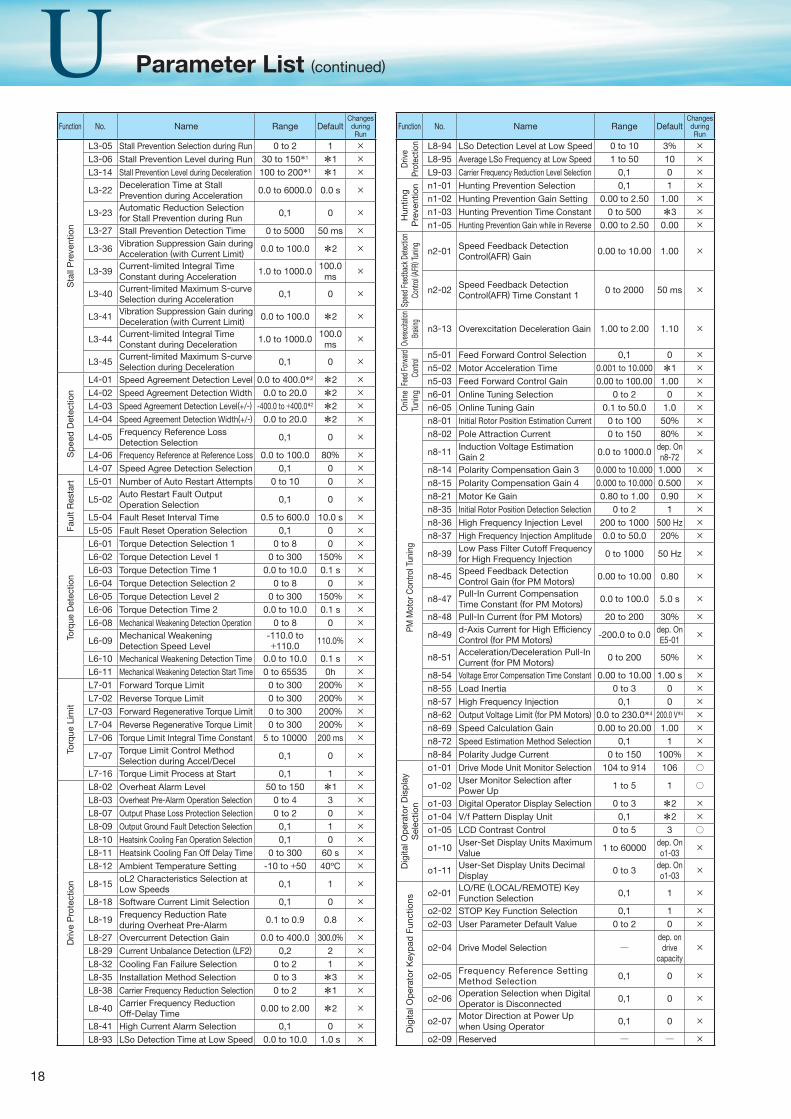
Function No. Name Range DefaultChanges
duringRun
Sta
ll P
reve
ntio
n
L3-05 Stall Prevention Selection during Run 0 to 2 1 ×L3-06 Stall Prevention Level during Run 30 to 150*1 *1 ×L3-14 Stall Prevention Level during Deceleration 100 to 200*1 *1 ×
L3-22 Deceleration Time at Stall Prevention during Acceleration
0.0 to 6000.0 0.0 s ×
L3-23 Automatic Reduction Selection for Stall Prevention during Run
0,1 0 ×
L3-27 Stall Prevention Detection Time 0 to 5000 50 ms ×
L3-36 Vibration Suppression Gain during Acceleration (with Current Limit)
0.0 to 100.0 *2 ×
L3-39 Current-limited Integral Time Constant during Acceleration
1.0 to 1000.0 100.0 ms
×
L3-40 Current-limited Maximum S-curve Selection during Acceleration
0,1 0 ×
L3-41 Vibration Suppression Gain during Deceleration (with Current Limit)
0.0 to 100.0 *2 ×
L3-44 Current-limited Integral Time Constant during Deceleration
1.0 to 1000.0 100.0 ms
×
L3-45 Current-limited Maximum S-curve Selection during Deceleration
0,1 0 ×
Sp
eed
Det
ectio
n
L4-01 Speed Agreement Detection Level 0.0 to 400.0*2 *2 ×L4-02 Speed Agreement Detection Width 0.0 to 20.0 *2 ×L4-03 Speed Agreement Detection Level(+/-) -400.0 to +400.0*2 *2 ×L4-04 Speed Agreement Detection Width(+/-) 0.0 to 20.0 *2 ×
L4-05 Frequency Reference Loss Detection Selection
0,1 0 ×
L4-06 Frequency Reference at Reference Loss 0.0 to 100.0 80% ×L4-07 Speed Agree Detection Selection 0,1 0 ×
Faul
t R
esta
rt L5-01 Number of Auto Restart Attempts 0 to 10 0 ×
L5-02 Auto Restart Fault Output Operation Selection
0,1 0 ×
L5-04 Fault Reset Interval Time 0.5 to 600.0 10.0 s ×L5-05 Fault Reset Operation Selection 0,1 0 ×
Torq
ue D
etec
tion
L6-01 Torque Detection Selection 1 0 to 8 0 ×L6-02 Torque Detection Level 1 0 to 300 150% ×L6-03 Torque Detection Time 1 0.0 to 10.0 0.1 s ×L6-04 Torque Detection Selection 2 0 to 8 0 ×L6-05 Torque Detection Level 2 0 to 300 150% ×L6-06 Torque Detection Time 2 0.0 to 10.0 0.1 s ×L6-08 Mechanical Weakening Detection Operation 0 to 8 0 ×
L6-09 Mechanical Weakening Detection Speed Level
-110.0 to +110.0 110.0% ×
L6-10 Mechanical Weakening Detection Time 0.0 to 10.0 0.1 s ×L6-11 Mechanical Weakening Detection Start Time 0 to 65535 0h ×
Torq
ue L
imit
L7-01 Forward Torque Limit 0 to 300 200% ×L7-02 Reverse Torque Limit 0 to 300 200% ×L7-03 Forward Regenerative Torque Limit 0 to 300 200% ×L7-04 Reverse Regenerative Torque Limit 0 to 300 200% ×L7-06 Torque Limit Integral Time Constant 5 to 10000 200 ms ×
L7-07 Torque Limit Control Method Selection during Accel/Decel
0,1 0 ×
L7-16 Torque Limit Process at Start 0,1 1 ×
Driv
e P
rote
ctio
n
L8-02 Overheat Alarm Level 50 to 150 *1 ×L8-03 Overheat Pre-Alarm Operation Selection 0 to 4 3 ×L8-07 Output Phase Loss Protection Selection 0 to 2 0 ×L8-09 Output Ground Fault Detection Selection 0,1 1 ×L8-10 Heatsink Cooling Fan Operation Selection 0,1 0 ×L8-11 Heatsink Cooling Fan Off Delay Time 0 to 300 60 s ×L8-12 Ambient Temperature Setting -10 to +50 40ºC ×
L8-15 oL2 Characteristics Selection at Low Speeds
0,1 1 ×
L8-18 Software Current Limit Selection 0,1 0 ×
L8-19 Frequency Reduction Rate during Overheat Pre-Alarm
0.1 to 0.9 0.8 ×
L8-27 Overcurrent Detection Gain 0.0 to 400.0 300.0% ×L8-29 Current Unbalance Detection (LF2) 0,2 2 ×L8-32 Cooling Fan Failure Selection 0 to 2 1 ×L8-35 Installation Method Selection 0 to 3 *3 ×L8-38 Carrier Frequency Reduction Selection 0 to 2 *1 ×
L8-40 Carrier Frequency Reduction Off-Delay Time
0.00 to 2.00 *2 ×
L8-41 High Current Alarm Selection 0,1 0 ×L8-93 LSo Detection Time at Low Speed 0.0 to 10.0 1.0 s ×
Function No. Name Range DefaultChanges
duringRun
Driv
e Pr
otec
tion L8-94 LSo Detection Level at Low Speed 0 to 10 3% ×
L8-95 Average LSo Frequency at Low Speed 1 to 50 10 ×L9-03 Carrier Frequency Reduction Level Selection 0,1 0 ×
Hun
ting
Pre
vent
ion n1-01 Hunting Prevention Selection 0,1 1 ×
n1-02 Hunting Prevention Gain Setting 0.00 to 2.50 1.00 ×n1-03 Hunting Prevention Time Constant 0 to 500 *3 ×n1-05 Hunting Prevention Gain while in Reverse 0.00 to 2.50 0.00 ×
Spee
d Fe
edba
ck D
etecti
on
Cont
rol ( A
FR) T
uning n2-01 Speed Feedback Detection
Control(AFR) Gain0.00 to 10.00 1.00 ×
n2-02 Speed Feedback Detection Control(AFR) Time Constant 1 0 to 2000 50 ms ×
Overe
xcita
tion
Brak
ing n3-13 Overexcitation Deceleration Gain 1.00 to 2.00 1.10 ×
Feed
Forw
ard
Contr
ol n5-01 Feed Forward Control Selection 0,1 0 ×n5-02 Motor Acceleration Time 0.001 to 10.000 *1 ×n5-03 Feed Forward Control Gain 0.00 to 100.00 1.00 ×
Onl
ine
Tuni
ng n6-01 Online Tuning Selection 0 to 2 0 ×n6-05 Online Tuning Gain 0.1 to 50.0 1.0 ×
PM M
otor
Con
trol T
unin
gn8-01 Initial Rotor Position Estimation Current 0 to 100 50% ×n8-02 Pole Attraction Current 0 to 150 80% ×
n8-11 Induction Voltage Estimation Gain 2 0.0 to 1000.0 dep. On
n8-72×
n8-14 Polarity Compensation Gain 3 0.000 to 10.000 1.000 ×n8-15 Polarity Compensation Gain 4 0.000 to 10.000 0.500 ×n8-21 Motor Ke Gain 0.80 to 1.00 0.90 ×n8-35 Initial Rotor Position Detection Selection 0 to 2 1 ×n8-36 High Frequency Injection Level 200 to 1000 500 Hz ×n8-37 High Frequency Injection Amplitude 0.0 to 50.0 20% ×
n8-39 Low Pass Filter Cutoff Frequency for High Frequency Injection
0 to 1000 50 Hz ×
n8-45 Speed Feedback Detection Control Gain (for PM Motors) 0.00 to 10.00 0.80 ×
n8-47 Pull-In Current Compensation Time Constant (for PM Motors) 0.0 to 100.0 5.0 s ×
n8-48 Pull-In Current (for PM Motors) 20 to 200 30% ×
n8-49 d-Axis Current for High Efficiency Control (for PM Motors) -200.0 to 0.0 dep. On
E5-01×
n8-51 Acceleration/Deceleration Pull-In Current (for PM Motors) 0 to 200 50% ×
n8-54 Voltage Error Compensation Time Constant 0.00 to 10.00 1.00 s ×n8-55 Load Inertia 0 to 3 0 ×n8-57 High Frequency Injection 0,1 0 ×n8-62 Output Voltage Limit (for PM Motors) 0.0 to 230.0*4 200.0 V*4 ×n8-69 Speed Calculation Gain 0.00 to 20.00 1.00 ×n8-72 Speed Estimation Method Selection 0,1 1 ×n8-84 Polarity Judge Current 0 to 150 100% ×
Dig
ital O
per
ator
Dis
pla
y S
elec
tion
o1-01 Drive Mode Unit Monitor Selection 104 to 914 106 ○
o1-02 User Monitor Selection after Power Up
1 to 5 1 ○
o1-03 Digital Operator Display Selection 0 to 3 *2 ×o1-04 V/f Pattern Display Unit 0,1 *2 ×o1-05 LCD Contrast Control 0 to 5 3 ○
o1-10 User-Set Display Units Maximum Value
1 to 60000 dep. On o1-03
×
o1-11 User-Set Display Units Decimal Display
0 to 3 dep. On o1-03
×
Dig
ital O
per
ator
Key
pad
Fun
ctio
ns
o2-01 LO/RE (LOCAL/REMOTE) Key Function Selection
0,1 1 ×
o2-02 STOP Key Function Selection 0,1 1 ×o2-03 User Parameter Default Value 0 to 2 0 ×
o2-04 Drive Model Selection ─dep. on
drive capacity
×
o2-05 Frequency Reference Setting Method Selection
0,1 0 ×
o2-06 Operation Selection when Digital Operator is Disconnected
0,1 0 ×
o2-07 Motor Direction at Power Up when Using Operator
0,1 0 ×
o2-09 Reserved ─ ─ ×
Parameter List (continued)
19
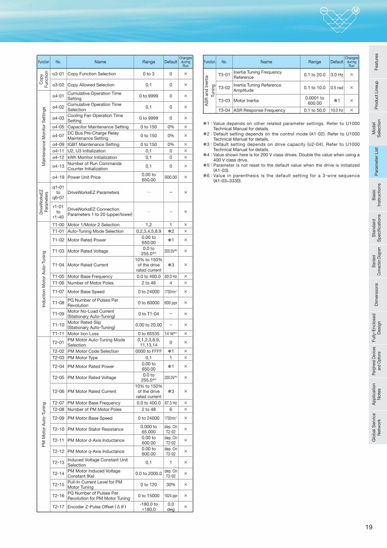
Function No. Name Range DefaultChanges
duringRun
Cop
y Fu
nctio
n o3-01 Copy Function Selection 0 to 3 0 ×
o3-02 Copy Allowed Selection 0,1 0 ×
Mai
nten
ance
Mon
itor
Set
tings
o4-01 Cumulative Operation Time Setting
0 to 9999 0 ×
o4-02 Cumulative Operation Time Selection
0,1 0 ×
o4-03 Cooling Fan Operation Time Setting
0 to 9999 0 ×
o4-05 Capacitor Maintenance Setting 0 to 150 0% ×
o4-07 DC Bus Pre-Charge Relay Maintenance Setting
0 to 150 0% ×
o4-09 IGBT Maintenance Setting 0 to 150 0% ×o4-11 U2, U3 Initialization 0,1 0 ×o4-12 kWh Monitor Initialization 0,1 0 ×
o4-13 Number of Run Commands Counter Initialization
0,1 0 ×
o4-19 Power Unit Price0.00 to 650.00 000.00 ×
Driv
eWor
ksEZ
P
aram
eter
s
q1-01 to
q6-07DriveWorksEZ Parameters ─ - ×
r1-01 to
r1-40
DriveWorksEZ Connection Parameters 1 to 20 (upper/lower)
─ - ×
Ind
uctio
n M
otor
Aut
o-Tu
ning
T1-00 Motor 1/Motor 2 Selection 1,2 1 ×T1-01 Auto-Tuning Mode Selection 0,2,3,4,5,8,9 *2 ×
T1-02 Motor Rated Power0.00 to 650.00 *1 ×
T1-03 Motor Rated Voltage0.0 to
255.0*4 200.0V*4 ×
T1-04 Motor Rated Current10% to 150%
of the drive rated current
*3 ×
T1-05 Motor Base Frequency 0.0 to 400.0 60.0 Hz ×T1-06 Number of Motor Poles 2 to 48 4 ×
T1-07 Motor Base Speed 0 to 24000 1750min-1 ×
T1-08 PG Number of Pulses Per Revolution
0 to 60000 600 ppr ×
T1-09 Motor No-Load Current(Stationary Auto-Tuning) 0 to T1-04 - ×
T1-10 Motor Rated Slip(Stationary Auto-Tuning) 0.00 to 20.00 - ×
T1-11 Motor Iron Loss 0 to 65535 14 W*1 ×
PM
Mot
or A
uto-
Tuni
ng
T2-01 PM Motor Auto-Tuning Mode Selection
0,1,2,3,8,9,11,13,14 0 ×
T2-02 PM Motor Code Selection 0000 to FFFF *1 ×T2-03 PM Motor Type 0,1 1 ×
T2-04 PM Motor Rated Power0.00 to 650.00 *1 ×
T2-05 PM Motor Rated Voltage0.0 to
255.0*4 200.0V*4 ×
T2-06 PM Motor Rated Current10% to 150%
of the drive rated current
*3 ×
T2-07 PM Motor Base Frequency 0.0 to 400.0 87.5 Hz ×T2-08 Number of PM Motor Poles 2 to 48 6 ×
T2-09 PM Motor Base Speed 0 to 24000 1750min-1 ×
T2-10 PM Motor Stator Resistance0.000 to 65.000
dep. On T2-02
×
T2-11 PM Motor d-Axis Inductance0.00 to 600.00
dep. On T2-02
×
T2-12 PM Motor q-Axis Inductance0.00 to 600.00
dep. On T2-02
×
T2-13 Induced Voltage Constant Unit Selection
0,1 1 ×
T2-14 PM Motor Induced Voltage Constant (Ke) 0.0 to 2000.0 dep. On
T2-02×
T2-15 Pull-In Current Level for PM Motor Tuning
0 to 120 30% ×
T2-16 PG Number of Pulses Per Revolution for PM Motor Tuning
0 to 15000 1024 ppr ×
T2-17 Encoder Z-Pulse Offset (Δθ ) -180.0 to +180.0
0.0 deg
×
Function No. Name Range DefaultChanges
duringRun
AS
R a
nd In
ertia
Tuni
ng
T3-01 Inertia Tuning Frequency Reference
0.1 to 20.0 3.0 Hz ×
T3-02 Inertia Tuning Reference Amplitude
0.1 to 10.0 0.5 rad ×
T3-03 Motor Inertia0.0001 to
600.00 *1 ×
T3-04 ASR Response Frequency 0.1 to 50.0 10.0 Hz ×
*1: Value depends on other related parameter settings. Refer to U1000 Technical Manual for details.
*2: Default setting depends on the control mode (A1-02). Refer to U1000 Technical Manual for details.
*3: Default setting depends on drive capacity (o2-04). Refer to U1000 Technical Manual for details.
*4: Value shown here is for 200 V class drives. Double the value when using a 400 V class drive.
*5: Parameter is not reset to the default value when the drive is initialized (A1-03).
*6: Value in parenthesis is the default setting for a 3-wire sequence (A1-03=3330).
Feat
ures
Pro
duct
Lin
eup
Mod
el
Sel
ectio
nP
aram
eter
Lis
tB
asic
In
stru
ctio
nsS
tand
ard
S
pec
ifi ca
tions
Stan
dard
Co
nnec
tion
Diag
ram
Dim
ensi
ons
Fully
- Enc
lose
d
Des
ign
Perip
hera
l Dev
ices
an
d O
ptio
nsA
pp
licat
ion
Not
esG
lob
al S
ervi
ce
Net
wor
kP
aram
eter
Lis
t
20
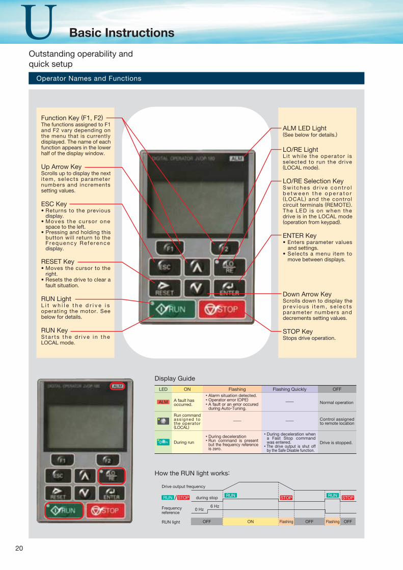
Function Key (F1, F2)The functions assigned to F1 and F2 vary depending on the menu that is currently displayed. The name of each function appears in the lower half of the display window.
Up Arrow KeyScrolls up to display the next i tem, se lects parameter numbers and increments setting values.
ESC KeyReturns to the previous display.Moves the cursor one space to the left.Pressing and holding this button will return to the F requency Re fe rence display.
RESET KeyMoves the cursor to the right.Resets the drive to clear a fault situation.
RUN LightL i t w h i l e t h e d r i v e i s operating the motor. See below for details.
RUN KeyS t a r t s t h e d r i v e i n t h e LOCAL mode.
Operator Names and Functions
Display Guide
How the RUN light works:
ONLED
A fault has occurred.
- Normal operation
- Control assigned to remote location
Drive is stopped.
Run command ass igned to the operator (LOCAL)
-
During run
Flashing Flashing Quickly OFF
ALM
OFFRUN light
/RUN during stop
Frequency reference
0 Hz6 Hz
Drive output frequency
ON Flashing Flashing OFFOFF
STOPSTOP STOPRUN RUN
ALM LED Light(See below for details.)
LO/RE LightLit whi le the operator is selected to run the drive (LOCAL mode).
LO/RE Selection KeyS w i t c h e s d r i v e c o n t r o l b e t w e e n t h e o p e r a t o r (LOCAL) and the control circuit terminals (REMOTE). The LED is on when the drive is in the LOCAL mode (operation from keypad).
ENTER Key Enters parameter values and settings.Selects a menu item to move between displays.
Down Arrow KeyScrolls down to display the p r e v i o u s i t e m , s e l e c t s parameter numbers and decrements setting values.
STOP KeyStops drive operation.
Alarm situation detected.Operator error (OPE)A fault or an error occured during Auto-Tuning.
During decelerationRun command is present but the frequency reference is zero.
During deceleration when a Fast Stop command was entered.The drive output is shut off by the Safe Disable function.
Outstanding operability and quick setup
Basic Instructions
21
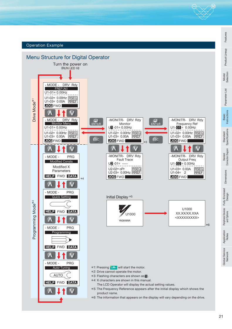
Turn the power on(RUN LED lit)
Pro
gra
mm
ing
Mo
de*
2
*4
Driv
e M
od
e*1
Initial Display *5
*6
*3
FREF(AI)
Monitor Menu Monitor Frequency Ref
Output FreqFault Trace
Modified XParameters
Modified Consts
Quick Setting
Programming
Auto-Tuning
Operation Example
Menu Structure for Digital Operator
*1: Pressing will start the motor.*2: Drive cannot operate the motor.*3: Flashing characters are shown as .*4: X characters are shown in this manual. The LCD Operator will display the actual setting values.*5: The Frequency Reference appears after the initial display which shows the product name.*6: The information that appears on the display will vary depending on the drive.
Feat
ures
Pro
duct
Lin
eup
Mod
el
Sel
ectio
nP
aram
eter
Lis
tB
asic
In
stru
ctio
nsS
tand
ard
S
pec
ifi ca
tions
Stan
dard
Co
nnec
tion
Diag
ram
Dim
ensi
ons
Fully
- Enc
lose
d
Des
ign
Perip
hera
l Dev
ices
an
d O
ptio
nsA
pp
licat
ion
Not
esG
lob
al S
ervi
ce
Net
wor
kB
asic
In
stru
ctio
ns
22
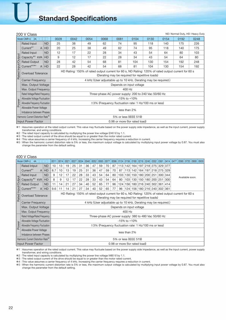
Standard Specifi cations
Model CIMR-U 2A 0028 0042 0054 0068 0081 0104 0130 0154 0192 0248
Rat
ed In
put
/Out
put
Rated Input
Current*1 A
ND 25 38 49 62 74 95 118 140 175 226
HD 20 25 38 49 62 74 95 118 140 175
Rated Input
Capacity*2 kVA
ND 12 17 22 28 34 43 54 64 80 103
HD 9 12 17 22 28 34 43 54 64 80
Rated Output
Current*3*4 A
ND 28 42 54 68 81 104 130 154 192 248
HD 22 28 42 54 68 81 104 130 154 192
Overload ToleranceHD Rating: 150% of rated output current for 60 s, ND Rating: 120% of rated output current for 60 s
(Derating may be required for repetitive loads)
Carrier Frequency 4 kHz (User adjustable up to 10 kHz. Derating may be required.)
Max. Output Voltage Depends on input voltage
Max. Output Frequency 400 Hz
Pow
er
Rated Voltage/Rated Frequency Three-phase AC power supply: 200 to 240 Vac 50/60 Hz
Allowable Voltage Fluctuation -15% to +10%Allowable Frequency Fluctuation ±3% (Frequency fl uctuation rate: 1 Hz/100 ms or less)
Allowable Power Voltage
Imbalance between Phasesless than 2%
Harmonic Current Distortion Rate*5 5% or less (IEEE 519)
Input Power Factor 0.98 or more (for rated load)
200 V Class
*1 : Assumes operation at the rated output current. This value may fl uctuate based on the power supply side impedance, as well as the input current, power supply transformer, and wiring conditions.
*2 : The rated input capacity is calculated by multiplying the power line voltage (240 V) by 1.1.
*3 : The rated output current of the drive should be equal to or greater than the motor rated current.
*4 : This value assumes a carrier frequency of 4 kHz. Increasing the carrier frequency requires a reduction in current.
*5 : When the harmonic current distortion rate is 5% or less, the maximum output voltage is calculated by multiplying input power voltage by 0.87. You must also change the parameter from the default setting.
Model CIMR-U 4A 0011 0014 0021 0027 0034 0040 0052 0065 0077 0096 0124 0156 0180 0216 0240 0302 0361 0414 0477 0590 0720 0900 0930
Rat
ed In
put
/Out
put
Rated Intput
Current*1 A
ND 10 13 19 25 31 36 47 59 70 87 113 142 164 197 218 275 329 377
Available soon.
HD 8.7 10 13 19 25 31 36 47 59 70 87 113 142 164 197 218 275 329
Rated Input
Capacity*2 kVA
ND 9 12 17 22 28 33 43 54 64 80 103 130 150 180 200 251 300 344
HD 8 9 12 17 22 28 33 43 54 64 80 103 130 150 180 200 251 300
Rated Output
Current*3*4 A
ND 11 14 21 27 34 40 52 65 77 96 124 156 180 216 240 302 361 414
HD 9.6 11 14 21 27 34 40 52 65 77 96 124 156 180 216 240 302 361
Overload ToleranceHD Rating: 150% of rated output current for 60 s, ND Rating: 120% of rated output current for 60 s
(Derating may be required for repetitive loads)
Carrier Frequency 4 kHz (User adjustable up to 10 kHz. Derating may be required.)
Max. Output Voltage Depends on input voltage
Max. Output Frequency 400 Hz
Pow
er
Rated Voltage/Rated Frequency Three-phase AC power supply: 380 to 480 Vac 50/60 Hz
Allowable Voltage Fluctuation -15% to +10%Allowable Frequency Fluctuation ±3% (Frequency fl uctuation rate: 1 Hz/100 ms or less)
Allowable Power Voltage
Imbalance between Phasesless than 2%
Harmonic Current Distortion Rate*5 5% or less (IEEE 519)
Input Power Factor 0.98 or more (for rated load)
400 V Class
*1 : Assumes operation at the rated output current. This value may fl uctuate based on the power supply side impedance, as well as the input current, power supply transformer, and wiring conditions.
*2 : The rated input capacity is calculated by multiplying the power line voltage (480 V) by 1.1.
*3 : The rated output current of the drive should be equal to or greater than the motor rated current.
*4 : This value assumes a carrier frequency of 4 kHz. Increasing the carrier frequency requires a reduction in current.
*5 : When the harmonic current distortion rate is 5% or less, the maximum output voltage is calculated by multiplying input power voltage by 0.87. You must also change the parameter from the default setting.
ND: Normal Duty, HD: Heavy Duty
23
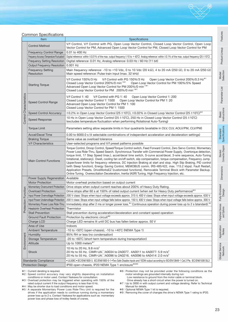
Item Specifi cations
Con
trol
Cha
ract
eris
tics
Control MethodV/f Control, V/f Control with PG, Open Loop Vector Control, Closed Loop Vector Control, Open Loop Vector Control for PM, Advanced Open Loop Vector Control for PM, Closed Loop Vector Control for PM
Frequency Control Range 0.01 to 400 HzFrequency Accuracy (Temperature Fluctuation) Digital reference: within ±0.01% of the max. output frequency (-10 to +40˚C) Analog reference: within ±0.1% of the max. output frequency (25 ±10˚C)
Frequency Setting Resolution Digital reference: 0.01 Hz, Analog reference: 0.03 Hz / 60 Hz (11 bit)
Output Frequency Resolution 0.001 Hz
Frequency Setting Resolution
Main frequency reference: -10 to +10 Vdc, 0 to 10 Vdc (20 kΩ ), 4 to 20 mA (250 Ω ), 0 to 20 mA (250 Ω ) Main speed reference: Pulse train input (max. 32 kHz)
Starting Torque
V/f Control 150%/3 Hz V/f Control with PG 150%/3 Hz Open Loop Vector Control 200%/0.3 Hz*1
Closed Loop Vector Control 200%/0 min-1*1 Open Loop Vector Control for PM 100%/5% SpeedAdvanced Open Loop Vector Control for PM 200%/0 min-1*1
Closed Loop Vector Control for PM 200%/0 min-1*1
Speed Control Range
V/f Control 1: 40 V/f Control with PG 1: 40 Open Loop Vector Control 1: 200Closed Loop Vector Control 1: 1500 Open Loop Vector Control for PM 1: 20Advanced Open Loop Vector Control for PM 1: 100Closed Loop Vector Control for PM 1: 1500
Speed Control Accuracy ±0.2% in Open Loop Vector Control (25 ±10˚C), ±0.02% in Closed Loop Vector Control (25 ±10˚C)*2
Speed Response10 Hz in Open Loop Vector Control (25 ±10˚C), 250 Hz in Closed Loop Vector Control (25 ±10˚C)(excludes temperature fl uctuation when performing Rotational Auto-Tuning)
Torque Limit Parameters setting allow separate limits in four quadrants (available in OLV, CLV, AOLV/PM, CLV/PM)
Accel/Decel Time 0.00 to 6000.0 s (4 selectable combinations of independent acceleration and deceleration settings)
Braking Torque Same value as overload toleranceV/f Characteristics User-selected programs and V/f preset patterns possible
Main Control Functions
Torque Control, Droop Control, Speed/Torque Control switch, Feed Forward Control, Zero Servo Control, Momentary Power Loss Ride-Thru, Speed Search,Synchronous Transfer with Commercial Power Supply,Overtorque detection, torque limit, 17 Step Speed (max.), accel/decel time switch, S-curve accel/decel, 3-wire sequence, Auto-Tuning (rotational, stationary),Dwell, cooling fan on/off switch, slip compensation, torque compensation, Frequency Jump,Upper/lower limits for frequency reference, DC Injection Braking at start and stop,High Slip Braking, PID control (with Sleep function), Energy Saving Control, MEMOBUS comm. (RS-485/422, max. 115.2 kbps),Fault Restart, Application Presets,DriveWorksEZ (customized functions), Removable Terminal Block with Parameter Backup,Online Tuning,Overexcitation Deceleration, Inertia (ASR) Tuning, High Frequency Injection, etc.
Pro
tect
ion
Func
tion
Power Supply Regeneration AvailableMotor Protection Motor overheat protection based on output currentMomentary Overcurrent Protection Drive stops when output current reaches about 200% of Heavy Duty Rating.Overload Protection Drive stops after 60 s at 150% of rated output current (when set for Heavy Duty performance)*3
Input Power Overvoltage Protection 200 V class: Stops when input voltage exceeds approx. 315 V, 400 V class: Stops when input voltage exceeds approx. 630 VInput Power Undervoltage Protection 200 V class: Stops when input voltage falls below approx. 150 V, 400 V class: Stops when input voltage falls below approx. 300 VMomentary Power Loss Ride-Thru Immediately stop after 2 ms or longer power loss.*4 Continuous operation during power loss up to 2 s (standard).*5
Heatsink Overheat Protection ThermistorStall Prevention Stall prevention during acceleration/deceleration and constant speed operationGround Fault Protection Protection by electronic circuit*6
Charge LCD Charge LED remains lit until DC bus has fallen below approx. 50 V
Env
ironm
ent
Area of Use IndoorsAmbient Temperature -10 to +50˚C (open-chassis), -10 to +40˚C (NEMA Type 1)
Humidity 95% RH or less (no condensation)
Storage Temperature -20 to +60˚C (short-term temperature during transportation)
Altitude Up to 1000 meters*7
Shock10 Hz to 20 Hz, 9.8 m/s2 20 Hz to 55 Hz,CIMR-UA A0034 to 2A0077,4A0011 to 4A0077: 5.9 m/s2 20 Hz to 55 Hz,CIMR-UA A0096 to 2A0216,4A0096 to 4A0414: 2.0 m/s2
Standards Compliance UL508C IEC/EN61800-3,IEC/EN61800-5-1 Two Safe Disable inputs and 1EDM output according to ISO/EN13849-1 Cat.3 Ple,IEC/EN61508 SIL3Protection Design IP00 open-chassis, IP20 NEMA Type 1 enclosure*8*9
Common Specifi cations
*1 : Current derating is required.
*2 : Speed control accuracy may vary slightly depending on installation conditions or motor used. Contact Yaskawa for consultation.
*3 : Overload protection may be triggered when operating with 150% of the rated output current if the output frequency is less than 6 Hz.
*4 : May be shorter due to load conditions and motor speed.
*5 : A separate Momentary Power Loss Ride-Thru Unit is required for the drives if the application needs to continue running during a momentary power loss up to 2 s. Contact Yaskawa for applications such as momentary power loss and phase loss of trolley feeds of cranes.
*6 : Protection may not be provided under the following conditions as the motor windings are grounded internally during run:
・Low resistance to ground from the motor cable or terminal block. ・Drive already has a short-circuit when the power is turned on.
*7 : Up to 3000 m with output current and voltage derating. Refer to Technical Manual for details.
*8 : Optional NEMA Type 1 kit is required.
*9 : Removing the cover of changes the drive's NEMA Type 1 rating to IP20.
Feat
ures
Pro
duct
Lin
eup
Mod
el
Sel
ectio
nP
aram
eter
Lis
tB
asic
In
stru
ctio
nsS
tand
ard
S
pec
ifi ca
tions
Stan
dard
Co
nnec
tion
Diag
ram
Dim
ensi
ons
Fully
- Enc
lose
d
Des
ign
Perip
hera
l Dev
ices
an
d O
ptio
nsA
pp
licat
ion
Not
esG
lob
al S
ervi
ce
Net
wor
kS
tand
ard
S
pec
ifi ca
tions
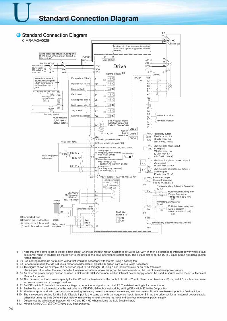
24
Standard Connection Diagram
+-
+-
R/L1S/L2T/L3
S1
S2
S3
S4
S5
S6
S7
DIP switch S2
Shield ground terminal
MP
DM+
DM-
Pulse train input
Main frequencyreference
Pulse train input (max 32 kHz)
Power supply +10.5 Vdc, max. 20 mAAnalog input 1(Frequency reference bias)0 to 10 Vdc (20 kΩ)
Analog input 2(Frequency reference bias)0 to 10 Vdc (20 kΩ)4 to 20 mA / 0 to 20 mA (250 Ω)Analog Input 3(Aux. frequency reference)0 to 10 Vdc (20 kΩ)
A3
+V
A1
A2
RP
0 V
AC
R+R-S+S-
IG
H1
H2
HC
Main Circuit
Control Circuit
Drive
n1p1
Termination resistor(120 Ω, 1/2 W)
Reverse run / Stop
Forward run / Stop
External fault
Fault reset
Multi-speed step 1
Multi-speed step 2
Jog speed
2 kΩ3
21
S8
SC
E(G)
External baseblock
MEMOBUS/Modbuscomm.
RS485/422max. 115.2 kbps
Sink / Source modeselection jumper S3(default: Sink)
4 to 20 mA
0 to 10 V
Pulse train output(Output frequency)0 to 32 kHz (2.2 kΩ)
FM
AM0 V
0 V
Multi-function analog mon(Output frequency)-10 to +10 Vdc (2 mA)
Multi-function analog mon(Output current)-10 to +10 Vdc (2 mA)
EDM (Safety Electronic Device Monitor)
AC
FM
AMAC
E (G)Wire
jumperOpen
Safetyswitch
S1
S2Safe Disable inputs
Safety relay /controller
*2
*11
*7
*10
*10
*8
*7
*5*6
DIP Switch S1V I
+24 V
-V Power supply, -10.5 Vdc, max. 20 mA
A+A-
B-
Z-
B+
Z+
AOIGBOIGZOIG
FE
IPIG
TB1
SD
TB2
PG-B3
B track monitor
A track monitor
MA
M1M2
P1
P2
MBMC
PC
Multi-function relay output(During run)250 Vac, max. 1 A30 Vdc, max 1 A(min. 5 Vdc, 10 mA)
Fault relay output250 Vac, max. 1 A30 Vdc, max. 1 A(min. 5 Vdc, 10 mA)
Multi-function photocoupler output 2(Speed agree)48 Vdc, max 50 mA
Multi-function photocoupler output 1(Zero speed)48 Vdc, max. 50 mA
CN5-C
CN5-B
CN5-A
Optionboard
connectors
M
U/T1V/T2W/T3
U
VW
Ground
Cooling fan
PG
*4
*9
M
FU
FVFW
2MCCB
Frequency Meter Adjusting Potentiom20 kΩ
Ammeter potentiometer20 kΩ
*12
0 to 10 V
Multi-functiondigital inputs(default setting)
Wiring sequence should shut off power to the drive when a fault output is triggered.
A separate transformer is required when running from a 400 V power supply to step the voltage down to 200 V.
ELCB or MCCBThree-phasepower supply200 to 240 V50/60 Hz
R
S
T
ONOFFTHRX
SA
1 2
TRX
MC MA
MC
TRX
Fault relay contact
Motor cooling fan thermal relay trip contact
MC
MC
SA
SA
THRX
2MCCBMC MB
Terminals p1, n1 are for connection options. Never connect power supply lines to these terminals.
*3
ONOFF
EMC filter switch*12
*1
* 1 : Note that if the drive is set to trigger a fault output whenever the fault restart function is activated (L5-02 = 1), then a sequence to interrupt power when a fault occurs will result in shutting off the power to the drive as the drive attempts to restart itself. The default setting for L5-02 is 0 (fault output not active during restart attempt).
* 2 : Self-cooling motors do not require wiring that would be necessary with motors using a cooling fan.
* 3 : For control modes that do not use a motor speed feedback signal, PG option card wiring is not necessary.
* 4: This fi gure shows an example of a sequence input to S1 through S8 using a non-powered relay or an NPN transistor. Use jumper S3 to select the sink mode for the use of an internal power supply or the source mode for the use of an external power supply.
* 5: An external power supply cannot be used in sink mode (+24 V common) and an internal power supply cannot be used in source mode. Refer to Technical Manual for details.
* 6 : The maximum output current capacity for the +V and −V terminals on the control circuit is 20 mA. Never short terminals +V, −V, and AC, as this can cause erroneous operation or damage the drive.
* 7: Set DIP switch S1 to select between a voltage or current input signal to terminal A2. The default setting is for current input.
* 8: Enable the termination resistor in the last drive in a MEMOBUS/Modbus network by setting DIP switch S2 to the ON position.
* 9: Monitor outputs work with devices such as analog frequency meters, ammeters, voltmeters, and wattmeters. Do not use these outputs in a feedback loop.
*10: The sink/source setting for the Safe Disable input is the same as with the sequence input. Jumper S3 has the drive set for an external power supply. When not using the Safe Disable input feature, remove the jumper shorting the input and connect an external power supply.
*11: Disconnect the wire jumper between H1 - HC and H2 - HC when utilizing the Safe Disable input.
*12: Models CIMR-U E / W have EMC fi lter switches.
Standard Connection DiagramCIMR-UA2A0028
shielded linetwisted-pair shielded l inema in c i rcu i t te rmina lcontrol circuit terminal
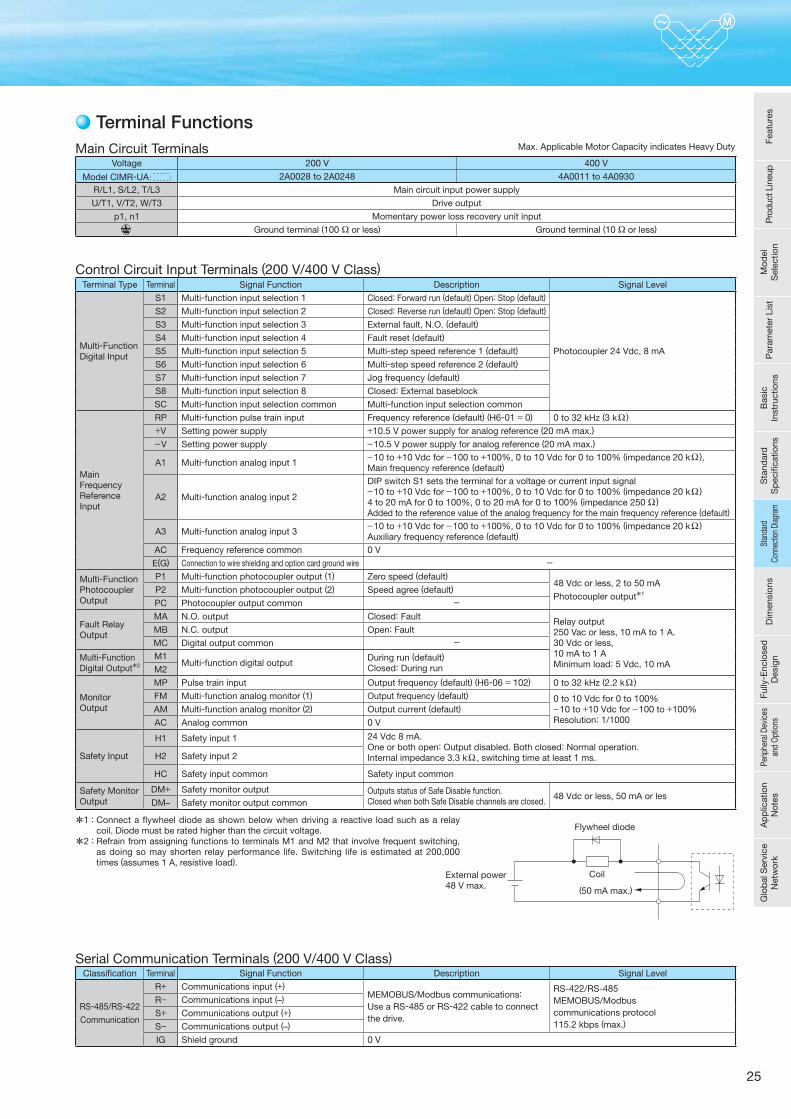
25
Voltage 200 V 400 V
Model CIMR-UA 2A0028 to 2A0248 4A0011 to 4A0930R/L1, S/L2, T/L3 Main circuit input power supply
U/T1, V/T2, W/T3 Drive output
p1, n1 Momentary power loss recovery unit input
Ground terminal (100 Ω or less) Ground terminal (10 Ω or less)
Main Circuit Terminals
Terminal Type Terminal Signal Function Description Signal Level
Multi-Function Digital Input
S1 Multi-function input selection 1 Closed: Forward run (default) Open: Stop (default)
Photocoupler 24 Vdc, 8 mA
S2 Multi-function input selection 2 Closed: Reverse run (default) Open: Stop (default)
S3 Multi-function input selection 3 External fault, N.O. (default)
S4 Multi-function input selection 4 Fault reset (default)
S5 Multi-function input selection 5 Multi-step speed reference 1 (default)
S6 Multi-function input selection 6 Multi-step speed reference 2 (default)
S7 Multi-function input selection 7 Jog frequency (default)
S8 Multi-function input selection 8 Closed: External baseblock
SC Multi-function input selection common Multi-function input selection common
Main Frequency Reference Input
RP Multi-function pulse train input Frequency reference (default) (H6-01 = 0) 0 to 32 kHz (3 kΩ )
+V Setting power supply +10.5 V power supply for analog reference (20 mA max.)
−V Setting power supply −10.5 V power supply for analog reference (20 mA max.)
A1 Multi-function analog input 1−10 to +10 Vdc for −100 to +100%, 0 to 10 Vdc for 0 to 100% (impedance 20 kΩ ), Main frequency reference (default)
A2 Multi-function analog input 2
DIP switch S1 sets the terminal for a voltage or current input signal−10 to +10 Vdc for −100 to +100%, 0 to 10 Vdc for 0 to 100% (impedance 20 kΩ ) 4 to 20 mA for 0 to 100%, 0 to 20 mA for 0 to 100% (impedance 250 Ω ) Added to the reference value of the analog frequency for the main frequency reference (default)
A3 Multi-function analog input 3−10 to +10 Vdc for −100 to +100%, 0 to 10 Vdc for 0 to 100% (impedance 20 kΩ ) Auxiliary frequency reference (default)
AC Frequency reference common 0 V
E(G) Connection to wire shielding and option card ground wire -
Multi-Function Photocoupler Output
P1 Multi-function photocoupler output (1) Zero speed (default) 48 Vdc or less, 2 to 50 mA
Photocoupler output*1P2 Multi-function photocoupler output (2) Speed agree (default)
PC Photocoupler output common -
Fault Relay Output
MA N.O. output Closed: Fault Relay output250 Vac or less, 10 mA to 1 A,30 Vdc or less,10 mA to 1 AMinimum load: 5 Vdc, 10 mA
MB N.C. output Open: Fault
MC Digital output common -
Multi-Function Digital Output*2
M1Multi-function digital output
During run (default)Closed: During runM2
Monitor Output
MP Pulse train input Output frequency (default) (H6-06 = 102) 0 to 32 kHz (2.2 kΩ )
FM Multi-function analog monitor (1) Output frequency (default) 0 to 10 Vdc for 0 to 100%−10 to +10 Vdc for −100 to +100%Resolution: 1/1000
AM Multi-function analog monitor (2) Output current (default)
AC Analog common 0 V
Safety Input
H1 Safety input 1 24 Vdc 8 mA. One or both open: Output disabled. Both closed: Normal operation.Internal impedance 3.3 kΩ , switching time at least 1 ms.H2 Safety input 2
HC Safety input common Safety input common
Safety Monitor Output
DM+ Safety monitor output Outputs status of Safe Disable function. Closed when both Safe Disable channels are closed.
48 Vdc or less, 50 mA or lesDM– Safety monitor output common
Control Circuit Input Terminals (200 V/400 V Class)
*1 : Connect a fl ywheel diode as shown below when driving a reactive load such as a relay coil. Diode must be rated higher than the circuit voltage.
*2 : Refrain from assigning functions to terminals M1 and M2 that involve frequent switching, as doing so may shorten relay performance life. Switching life is estimated at 200,000 times (assumes 1 A, resistive load).
Classifi cation Terminal Signal Function Description Signal Level
RS-485/RS-422Communication
R+ Communications input (+)MEMOBUS/Modbus communications: Use a RS-485 or RS-422 cable to connect the drive.
RS-422/RS-485MEMOBUS/Modbuscommunications protocol115.2 kbps (max.)
R− Communications input (–)
S+ Communications output (+)
S− Communications output (–)
IG Shield ground 0 V
Serial Communication Terminals (200 V/400 V Class)
Terminal FunctionsMax. Applicable Motor Capacity indicates Heavy Duty
(50 mA max.)
CoilExternal power 48 V max.
Flywheel diode
Feat
ures
Pro
duct
Lin
eup
Mod
el
Sel
ectio
nP
aram
eter
Lis
tB
asic
In
stru
ctio
nsS
tand
ard
S
pec
ifi ca
tions
Stan
dard
Co
nnec
tion
Diag
ram
Dim
ensi
ons
Fully
- Enc
lose
d
Des
ign
Perip
hera
l Dev
ices
an
d O
ptio
nsA
pp
licat
ion
Not
esG
lob
al S
ervi
ce
Net
wor
kSt
anda
rd
Conn
ectio
n Di
agra
m
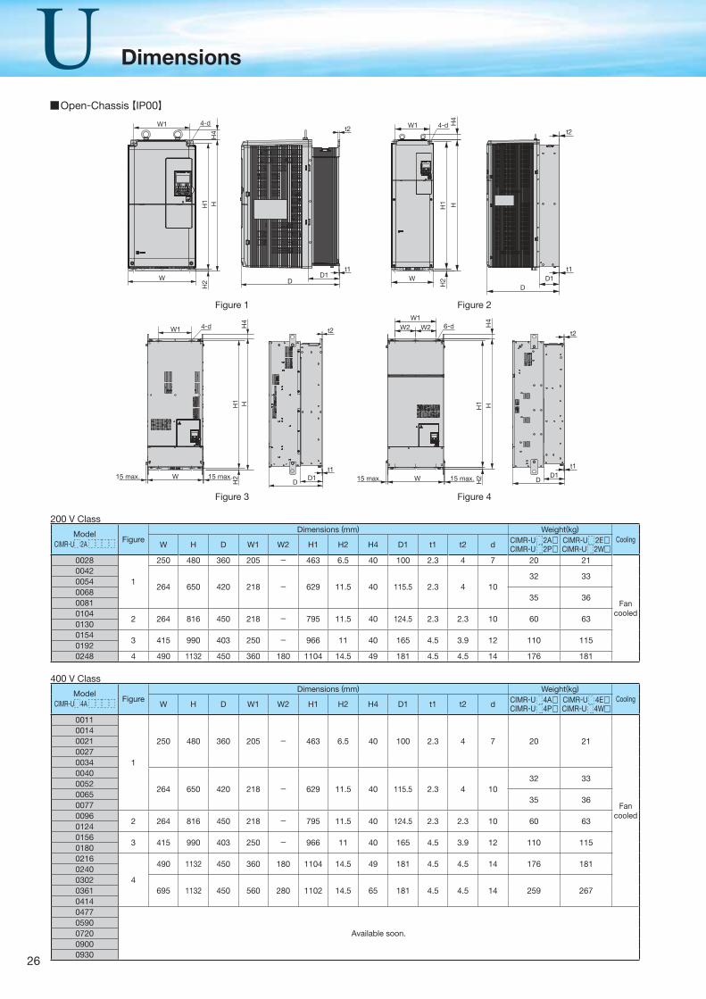
26
Dimensions
W1 4-d 4-dW1
W D1D
H1
H2
HH
4
t1
t2
W
H1 H
H4
H2
t1
t2
D1D
W1
W15 max. 15 max.
H2
HH
4H
1
4-d
t1D1
D
t2
W15 max. 15 max. H2
H1 H
H4
W2W1
W2 6-d
t1
t2
D1D
Open-Chassis【IP00】
Figure 1 Figure 2
Figure 3 Figure 4
ModelCIMR-U 2A
FigureDimensions (mm) Weight(kg)
CoolingW H D W1 W2 H1 H2 H4 D1 t1 t2 d CIMR-U 2A
CIMR-U 2PCIMR-U 2ECIMR-U 2W
0028
1
250 480 360 205 - 463 6.5 40 100 2.3 4 7 20 21
Fancooled
0042
264 650 420 218 - 629 11.5 40 115.5 2.3 4 1032 33
00540068
35 3600810104
2 264 816 450 218 - 795 11.5 40 124.5 2.3 2.3 10 60 6301300154
3 415 990 403 250 - 966 11 40 165 4.5 3.9 12 110 11501920248 4 490 1132 450 360 180 1104 14.5 49 181 4.5 4.5 14 176 181
ModelCIMR-U 4A
FigureDimensions (mm) Weight(kg)
CoolingW H D W1 W2 H1 H2 H4 D1 t1 t2 d CIMR-U 4A
CIMR-U 4PCIMR-U 4ECIMR-U 4W
0011
1
250 480 360 205 - 463 6.5 40 100 2.3 4 7 20 21
Fancooled
00140021002700340040
264 650 420 218 - 629 11.5 40 115.5 2.3 4 1032 33
00520065
35 3600770096
2 264 816 450 218 - 795 11.5 40 124.5 2.3 2.3 10 60 6301240156
3 415 990 403 250 - 966 11 40 165 4.5 3.9 12 110 11501800216
4
490 1132 450 360 180 1104 14.5 49 181 4.5 4.5 14 176 18102400302
695 1132 450 560 280 1102 14.5 65 181 4.5 4.5 14 259 267036104140477
Available soon.0590072009000930
400 V Class
200 V Class
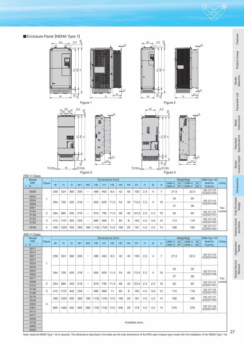
27
W1 W14-d
WD1
D
t1
D1D
t1
H3
H1
H2
HH
4
H4
H0
t2 t24-d
W H3
H1
H2
HH0
W1W1W2 W2
4-d6-d
W 15 max.15 max.W 15 max.15 max.
D1D
t1
H3
H1
H2
HH
4H
0
H3
H1
H2
HH
4H
0
t2
D1D
t1
t2
Figure 1 Figure 2
Figure 3 Figure 4
Enclosure Panel 【NEMA Type 1】
ModelCIMR-
U 2A Figure
Dimensions (mm) Weight(kg) NEMA Type 1 KitModel No.(Code No.)
CoolingW H D W1 W2 H0 H1 H2 H3 H4 D1 t1 t2 d CIMR-U 2A
CIMR-U 2PCIMR-U 2ECIMR-U 2W
0028
1
250 524 360 205 - 480 463 6.5 42 40 100 2.3 4 7 21.5 22.5 100-127-413(EZZ022745A)
Fancooled
0042
264 705 420 218 - 650 629 11.5 54 40 115.5 2.3 4 1034 35
100-127-414(EZZ022745B)
00540068
37 3800810104
2 264 885 450 218 - 816 795 11.5 68 40 124.5 2.3 2.3 10 62 65 100-127-415(EZZ022745C)0130
01543 415 1107 403 250 - 990 966 11 85 8 165 4.5 3.9 12 113 118 100-127-416
(EZZ022745D)0192
0248 4 490 1320 450 360 180 1132 1104 14.5 169 29 181 4.5 4.5 14 180 185 100-127-417(EZZ022745E)
ModelCIMR-
U 4A Figure
Dimensions (mm) Weight(kg) NEMA Type 1 KitModel No.(Code No.)
CoolingW H D W1 W2 H0 H1 H2 H3 H4 D1 t1 t2 d CIMR-U 4A
CIMR-U 4PCIMR-U 4ECIMR-U 4W
0011
1
250 524 360 205 - 480 463 6.5 42 40 100 2.3 4 7 21.5 22.5 100-127-413(EZZ022745A)
Fancooled
00140021002700340040
264 705 420 218 - 650 629 11.5 54 40 115.5 2.3 4 1034 35
100-127-414(EZZ022745B)
00520065
37 3800770096
2 264 885 450 218 - 816 795 11.5 68 40 124.5 2.3 2.3 10 62 65 100-127-415(EZZ022745C)0124
01563 415 1107 403 250 - 990 966 11 85 8 165 4.5 3.9 12 113 118 100-127-416
(EZZ022745D)01800216
4
490 1320 450 360 180 1132 1104 14.5 169 29 181 4.5 4.5 14 180 185 100-127-417(EZZ022745E)0240
0302695 1460 450 560 280 1132 1102 14.5 300 29 178 4.5 4.5 14 270 278 100-127-418
(EZZ022745F)036104140477
Available soon.0590072009000930
400 V Class
200 V Class
Note: Optional NEMA Type 1 kit is required. The dimensions described in the table are the total dimensions of the IP00 open-chassis type model with the installation of the NEMA Type 1 kit.
Feat
ures
Pro
duct
Lin
eup
Mod
el
Sel
ectio
nP
aram
eter
Lis
tB
asic
In
stru
ctio
nsS
tand
ard
S
pec
ifi ca
tions
Stan
dard
Co
nnec
tion
Diag
ram
Dim
ensi
ons
Fully
- Enc
lose
d
Des
ign
Perip
hera
l Dev
ices
an
d O
ptio
nsA
pp
licat
ion
Not
esG
lob
al S
ervi
ce
Net
wor
kD
imen
sion
s
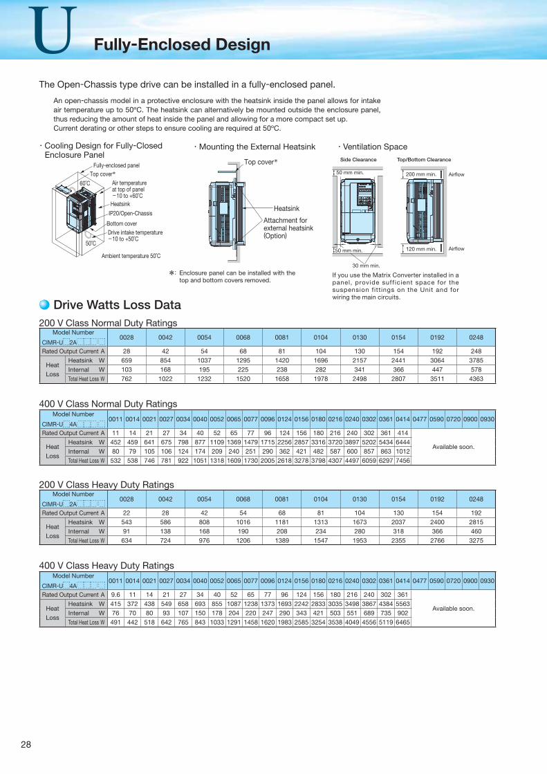
28
Fully-Enclosed Design
・Cooling Design for Fully-Closed Enclosure Panel
・Ventilation Space
*: Enclosure panel can be installed with the top and bottom covers removed.
Model Number
CIMR-U 2A0028 0042 0054 0068 0081 0104 0130 0154 0192 0248
Rated Output Current A 28 42 54 68 81 104 130 154 192 248
Heat
Loss
Heatsink W 659 854 1037 1295 1420 1696 2157 2441 3064 3785Internal W 103 168 195 225 238 282 341 366 447 578Total Heat Loss W 762 1022 1232 1520 1658 1978 2498 2807 3511 4363
200 V Class Normal Duty Ratings
Drive Watts Loss Data
Model Number
CIMR-U 2A0028 0042 0054 0068 0081 0104 0130 0154 0192 0248
Rated Output Current A 22 28 42 54 68 81 104 130 154 192
Heat
Loss
Heatsink W 543 586 808 1016 1181 1313 1673 2037 2400 2815Internal W 91 138 168 190 208 234 280 318 366 460Total Heat Loss W 634 724 976 1206 1389 1547 1953 2355 2766 3275
200 V Class Heavy Duty Ratings
The Open-Chassis type drive can be installed in a fully-enclosed panel.
If you use the Matrix Converter installed in a panel, provide suf f icient space for the suspension f it tings on the Unit and for wiring the main circuits.
Fully-enclosed panel
60˚C
50˚C
Top cover*Air temperatureat top of panel-10 to +60˚C
IP20/Open-Chassis
Drive intake temperature-10 to +50˚C
Ambient temperature 50˚C
Bottom cover
Heatsink
Top cover*
Heatsink
Attachment forexternal heatsink(Option)
200 mm min. Airflow
Airflow120 mm min.
50 mm min.
Side Clearance Top/Bottom Clearance
50 mm min.
30 mm min.
An open-chassis model in a protective enclosure with the heatsink inside the panel allows for intake air temperature up to 50ºC. The heatsink can alternatively be mounted outside the enclosure panel, thus reducing the amount of heat inside the panel and allowing for a more compact set up.Current derating or other steps to ensure cooling are required at 50ºC.
・Mounting the External Heatsink
Model Number
CIMR-U 4A0011 0014 0021 0027 0034 0040 0052 0065 0077 0096 0124 0156 0180 0216 0240 0302 0361 0414 0477 0590 0720 0900 0930
Rated Output Current A 11 14 21 27 34 40 52 65 77 96 124 156 180 216 240 302 361 414
Available soon.Heat
Loss
Heatsink W 452 459 641 675 798 877 1109 1369 1479 1715 2256 2857 3316 3720 3897 5202 5434 6444Internal W 80 79 105 106 124 174 209 240 251 290 362 421 482 587 600 857 863 1012Total Heat Loss W 532 538 746 781 922 1051 1318 1609 1730 2005 2618 3278 3798 4307 4497 6059 6297 7456
400 V Class Normal Duty Ratings
Model Number
CIMR-U 4A0011 0014 0021 0027 0034 0040 0052 0065 0077 0096 0124 0156 0180 0216 0240 0302 0361 0414 0477 0590 0720 0900 0930
Rated Output Current A 9.6 11 14 21 27 34 40 52 65 77 96 124 156 180 216 240 302 361
Available soon.Heat
Loss
Heatsink W 415 372 438 549 658 693 855 1087 1238 1373 1693 2242 2833 3035 3498 3867 4384 5563Internal W 76 70 80 93 107 150 178 204 220 247 290 343 421 503 551 689 735 902Total Heat Loss W 491 442 518 642 765 843 1033 1291 1458 1620 1983 2585 3254 3538 4049 4556 5119 6465
400 V Class Heavy Duty Ratings
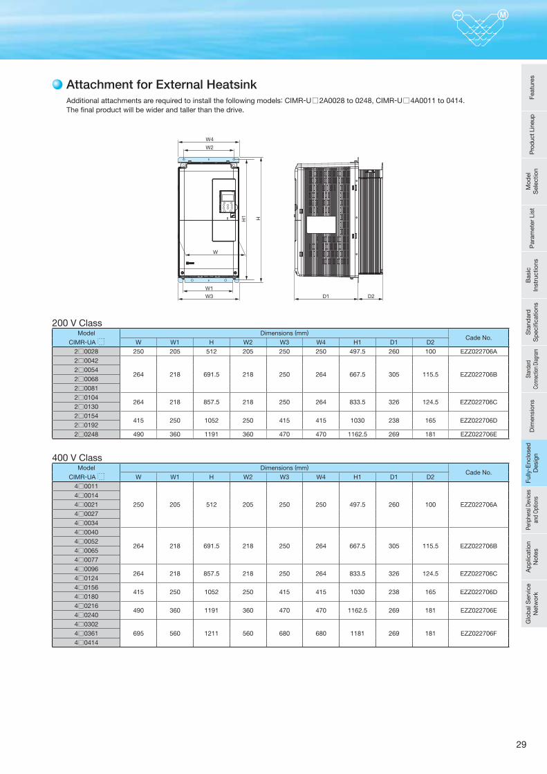
29
Attachment for External Heatsink
Feat
ures
Pro
duct
Lin
eup
Mod
el
Sel
ectio
nP
aram
eter
Lis
tB
asic
In
stru
ctio
nsS
tand
ard
S
pec
ifi ca
tions
Stan
dard
Co
nnec
tion
Diag
ram
Dim
ensi
ons
Fully
- Enc
lose
d
Des
ign
Perip
hera
l Dev
ices
an
d O
ptio
nsA
pp
licat
ion
Not
esG
lob
al S
ervi
ce
Net
wor
kFu
lly- E
nclo
sed
D
esig
n
200 V ClassModel
CIMR-UA
Dimensions (mm)Cade No.
W W1 H W2 W3 W4 H1 D1 D22 0028 250 205 512 205 250 250 497.5 260 100 EZZ022706A
2 0042
264 218 691.5 218 250 264 667.5 305 115.5 EZZ022706B2 00542 00682 00812 0104
264 218 857.5 218 250 264 833.5 326 124.5 EZZ022706C2 01302 0154
415 250 1052 250 415 415 1030 238 165 EZZ022706D2 01922 0248 490 360 1191 360 470 470 1162.5 269 181 EZZ022706E
400 V ClassModel
CIMR-UA
Dimensions (mm)Cade No.
W W1 H W2 W3 W4 H1 D1 D24 0011
250 205 512 205 250 250 497.5 260 100 EZZ022706A
4 00144 00214 00274 00344 0040
264 218 691.5 218 250 264 667.5 305 115.5 EZZ022706B4 00524 00654 00774 0096
264 218 857.5 218 250 264 833.5 326 124.5 EZZ022706C4 01244 0156
415 250 1052 250 415 415 1030 238 165 EZZ022706D4 01804 0216
490 360 1191 360 470 470 1162.5 269 181 EZZ022706E4 02404 0302
695 560 1211 560 680 680 1181 269 181 EZZ022706F4 03614 0414
W2
W4
W1
W
D1 D2W3
H1 H
Additional attachments are required to install the following models: CIMR-U□2A0028 to 0248, CIMR-U□4A0011 to 0414.The final product will be wider and taller than the drive.
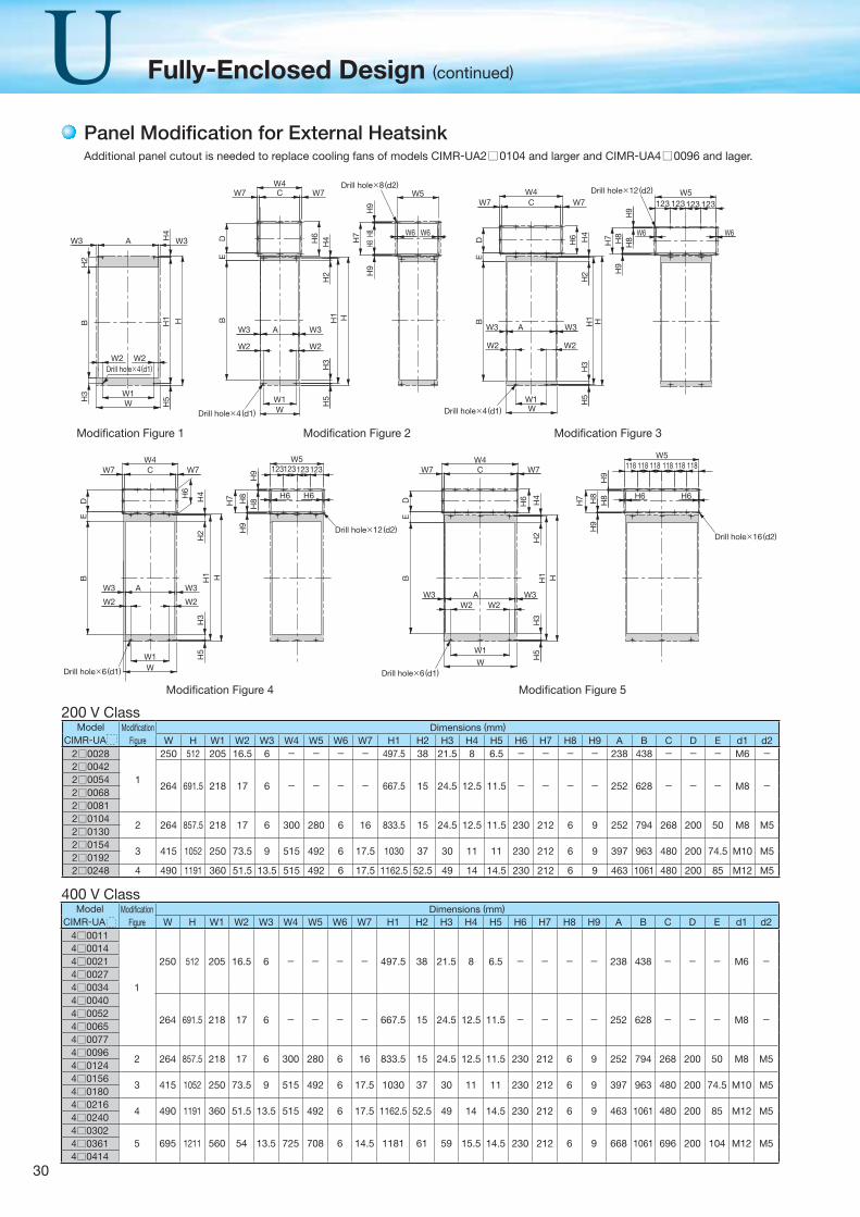
30
Fully-Enclosed Design (continued)
Panel Modifi cation for External Heatsink
ModelCIMR-UA
Modifi cation Figure
Dimensions (mm)W H W1 W2 W3 W4 W5 W6 W7 H1 H2 H3 H4 H5 H6 H7 H8 H9 A B C D E d1 d2
2 0028
1
250 512 205 16.5 6 - - - - 497.5 38 21.5 8 6.5 - - - - 238 438 - - - M6 -2 0042
264 691.5 218 17 6 - - - - 667.5 15 24.5 12.5 11.5 - - - - 252 628 - - - M8 -2 00542 00682 00812 0104
2 264 857.5 218 17 6 300 280 6 16 833.5 15 24.5 12.5 11.5 230 212 6 9 252 794 268 200 50 M8 M52 01302 0154
3 415 1052 250 73.5 9 515 492 6 17.5 1030 37 30 11 11 230 212 6 9 397 963 480 200 74.5 M10 M52 01922 0248 4 490 1191 360 51.5 13.5 515 492 6 17.5 1162.5 52.5 49 14 14.5 230 212 6 9 463 1061 480 200 85 M12 M5
200 V Class
400 V ClassModel
CIMR-UAModifi cation
FigureDimensions (mm)
W H W1 W2 W3 W4 W5 W6 W7 H1 H2 H3 H4 H5 H6 H7 H8 H9 A B C D E d1 d24 0011
1
250 512 205 16.5 6 - - - - 497.5 38 21.5 8 6.5 - - - - 238 438 - - - M6 -4 00144 00214 00274 00344 0040
264 691.5 218 17 6 - - - - 667.5 15 24.5 12.5 11.5 - - - - 252 628 - - - M8 -4 00524 00654 00774 0096
2 264 857.5 218 17 6 300 280 6 16 833.5 15 24.5 12.5 11.5 230 212 6 9 252 794 268 200 50 M8 M54 01244 0156
3 415 1052 250 73.5 9 515 492 6 17.5 1030 37 30 11 11 230 212 6 9 397 963 480 200 74.5 M10 M54 01804 0216
4 490 1191 360 51.5 13.5 515 492 6 17.5 1162.5 52.5 49 14 14.5 230 212 6 9 463 1061 480 200 85 M12 M54 02404 0302
5 695 1211 560 54 13.5 725 708 6 14.5 1181 61 59 15.5 14.5 230 212 6 9 668 1061 696 200 104 M12 M54 03614 0414
W4W7 118 118 118 118 118 118W7 C
DE
B
H6 H4
H2
H1 H
H3
AW3 W3W2 W2
W1W
H5
Drill hole×6(d1)
W5
H9
H7 H8
H8
H9
H6 H6
Drill hole×16(d2)
Drill hole×4(d1)
AW3 W3H4
H1 H
W1W H
5
W2W2
H3
H2
B BE
D
W4W7 W7C
H6
H4
H2
W3 W3
W2 W2
A
W1W
H3
H5
H1 H
Drill hole×4(d1)
Drill hole×8(d2)
H9
W5
W6 W6
H7
H9
H8H8
W4CW7 W7
DE
B
H6 H4
H2
H1 H
W3
W2
W3
W2
A
H3
H5W1
WDrill hole×4(d1)
H7 H8
H8
W6 W6
W5123 123123 123
H9
H9
Drill hole×12(d2)H
3
W4W7 W7C
DE
B
AW3
W2
W3
W2
W1WDrill hole×6(d1)
H5
H6
H4
H2
H1 H
W5123123123123
H9
H9
H7 H8
H8
H6 H6
Drill hole×12(d2)
Modifi cation Figure 1 Modifi cation Figure 2 Modifi cation Figure 3
Modifi cation Figure 4 Modifi cation Figure 5
Additional panel cutout is needed to replace cooling fans of models CIMR-UA2□0104 and larger and CIMR-UA4□0096 and lager.
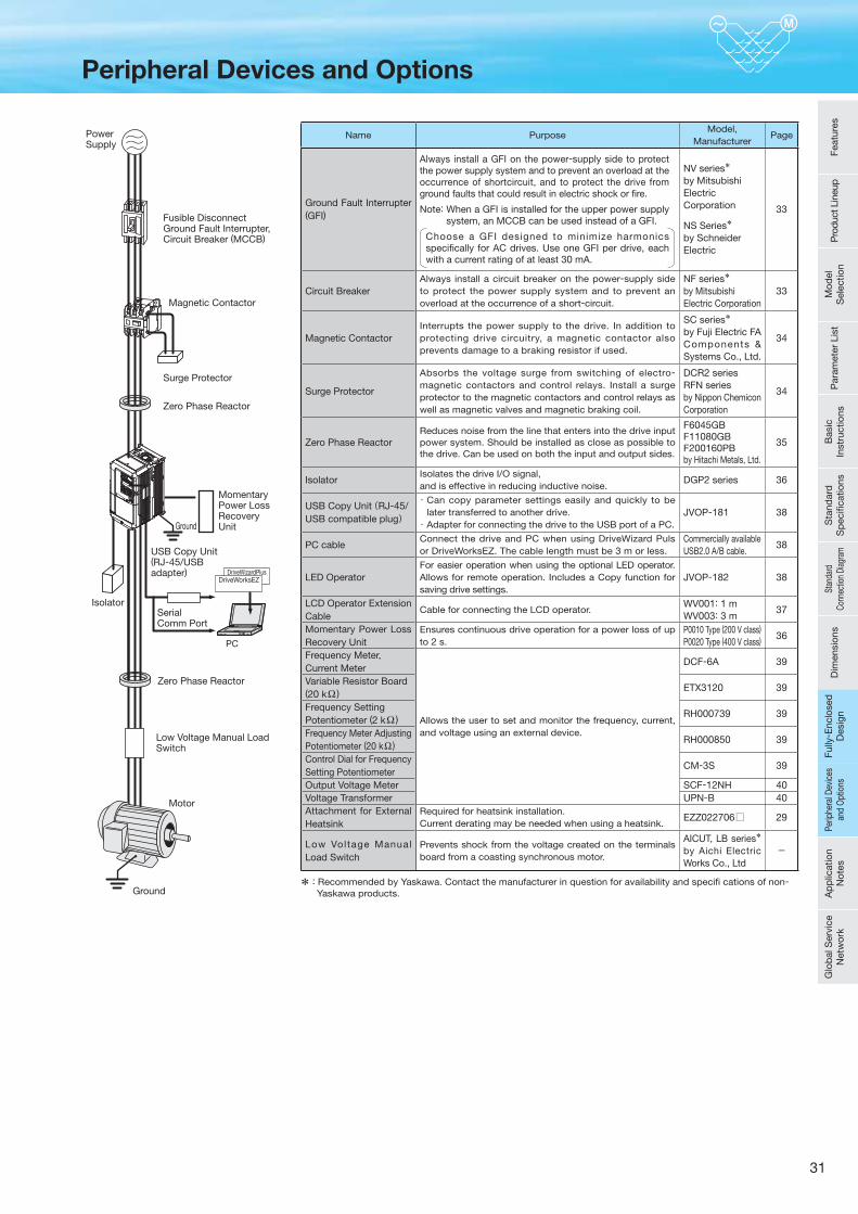
31
Zero Phase Reactor
Low Voltage Manual LoadSwitch
Motor
Ground
Zero Phase Reactor
DriveWizardPlus
PC
DriveWorksEZ
MomentaryPower LossRecovery UnitGround
SerialComm Port
USB Copy Unit (RJ-45/USBadapter)
PowerSupply
Magnetic Contactor
Fusible DisconnectGround Fault Interrupter,Circuit Breaker (MCCB)
Surge Protector
Isolator
Name PurposeModel,
ManufacturerPage
Ground Fault Interrupter (GFI)
Always install a GFI on the power-supply side to protect the power supply system and to prevent an overload at the occurrence of shortcircuit, and to protect the drive from ground faults that could result in electric shock or fi re.
Note: When a GFI is installed for the upper power supply system, an MCCB can be used instead of a GFI.
Choose a GFI designed to minimize harmonics specifi cally for AC drives. Use one GFI per drive, each with a current rating of at least 30 mA.
NV series* by MitsubishiElectric Corporation
NS Series* by SchneiderElectric
33
Circuit BreakerAlways install a circuit breaker on the power-supply side to protect the power supply system and to prevent an overload at the occurrence of a short-circuit.
NF series* by MitsubishiElectric Corporation
33
Magnetic ContactorInterrupts the power supply to the drive. In addition to protecting drive circuitry, a magnetic contactor also prevents damage to a braking resistor if used.
SC series* by Fuji Electric FAComponents & Systems Co., Ltd.
34
Surge Protector
Absorbs the voltage surge from switching of electro-magnetic contactors and control relays. Install a surge protector to the magnetic contactors and control relays as well as magnetic valves and magnetic braking coil.
DCR2 seriesRFN seriesby Nippon ChemiconCorporation
34
Zero Phase ReactorReduces noise from the line that enters into the drive input power system. Should be installed as close as possible to the drive. Can be used on both the input and output sides.
F6045GBF11080GBF200160PBby Hitachi Metals, Ltd.
35
IsolatorIsolates the drive I/O signal, and is effective in reducing inductive noise.
DGP2 series 36
USB Copy Unit(RJ-45/ USB compatible plug)
・ Can copy parameter settings easily and quickly to be later transferred to another drive.・ Adapter for connecting the drive to the USB port of a PC.
JVOP-181 38
PC cableConnect the drive and PC when using DriveWizard Puls or DriveWorksEZ. The cable length must be 3 m or less.
Commercially availableUSB2.0 A/B cable.
38
LED OperatorFor easier operation when using the optional LED operator. Allows for remote operation. Includes a Copy function for saving drive settings.
JVOP-182 38
LCD Operator Extension Cable
Cable for connecting the LCD operator.WV001: 1 mWV003: 3 m
37
Momentary Power Loss Recovery Unit
Ensures continuous drive operation for a power loss of up to 2 s.
P0010 Type (200 V class)P0020 Type (400 V class) 36
Frequency Meter, Current Meter
Allows the user to set and monitor the frequency, current, and voltage using an external device.
DCF-6A 39
Variable Resistor Board (20 kΩ ) ETX3120 39
Frequency Setting Potentiometer (2 kΩ ) RH000739 39
Frequency Meter Adjusting Potentiometer (20 kΩ ) RH000850 39
Control Dial for Frequency Setting Potentiometer
CM-3S 39
Output Voltage Meter SCF-12NH 40Voltage Transformer UPN-B 40Attachment for External Heatsink
Required for heatsink installation. Current derating may be needed when using a heatsink.
EZZ022706□ 29
Low Voltage Manual Load Switch
Prevents shock from the voltage created on the terminals board from a coasting synchronous motor.
AICUT, LB series* by Aichi Electric Works Co., Ltd
-
* : Recommended by Yaskawa. Contact the manufacturer in question for availability and specifi cations of non-Yaskawa products.
Peripheral Devices and Options
Feat
ures
Pro
duct
Lin
eup
Mod
el
Sel
ectio
nP
aram
eter
Lis
tB
asic
In
stru
ctio
nsS
tand
ard
S
pec
ifi ca
tions
Stan
dard
Co
nnec
tion
Diag
ram
Dim
ensi
ons
Fully
- Enc
lose
d
Des
ign
Perip
hera
l Dev
ices
an
d O
ptio
nsA
pp
licat
ion
Not
esG
lob
al S
ervi
ce
Net
wor
kPe
riphe
ral D
evic
es
and
Opt
ions
Fully
- Enc
lose
d
Des
ign
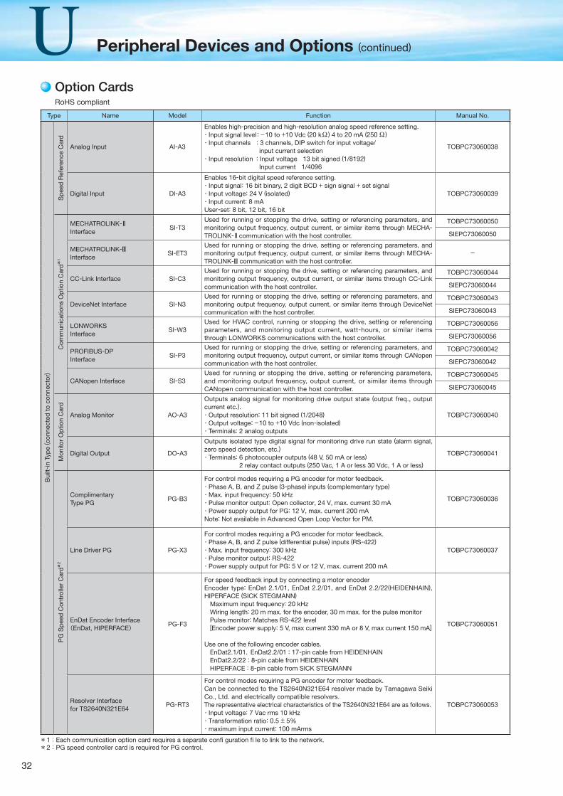
32
Peripheral Devices and Options (continued)
Type Name Model Function Manual No.
Bui
lt-in
Typ
e ( c
onne
cted
to
conn
ecto
r)
Sp
eed
Ref
eren
ce C
ard
Analog Input AI-A3
Enables high-precision and high-resolution analog speed reference setting.・Input signal level : −10 to +10 Vdc (20 kΩ ) 4 to 20 mA (250 Ω )・Input channels : 3 channels, DIP switch for input voltage/ input current selection・Input resolution : Input voltage 13 bit signed (1/8192) Input current 1/4096
TOBPC73060038
Digital Input DI-A3
Enables 16-bit digital speed reference setting.・Input signal: 16 bit binary, 2 digit BCD + sign signal + set signal・Input voltage: 24 V (isolated)・Input current: 8 mAUser-set: 8 bit, 12 bit, 16 bit
TOBPC73060039
Com
mun
icat
ions
Op
tion
Car
d*1
MECHATROLINK-Interface
SI-T3Used for running or stopping the drive, setting or referencing parameters, and monitoring output frequency, output current, or similar items through MECHA-TROLINK- communication with the host controller.
TOBPC73060050
SIEPC73060050
MECHATROLINK-Interface
SI-ET3Used for running or stopping the drive, setting or referencing parameters, and monitoring output frequency, output current, or similar items through MECHA-TROLINK- communication with the host controller.
-
CC-Link Interface SI-C3Used for running or stopping the drive, setting or referencing parameters, and monitoring output frequency, output current, or similar items through CC-Link communication with the host controller.
TOBPC73060044
SIEPC73060044
DeviceNet Interface SI-N3Used for running or stopping the drive, setting or referencing parameters, and monitoring output frequency, output current, or similar items through DeviceNet communication with the host controller.
TOBPC73060043
SIEPC73060043
LONWORKSInterface
SI-W3Used for HVAC control, running or stopping the drive, setting or referencing parameters, and monitoring output current, watt-hours, or similar items through LONWORKS communications with the host controller.
TOBPC73060056
SIEPC73060056
PROFIBUS-DPInterface
SI-P3Used for running or stopping the drive, setting or referencing parameters, and monitoring output frequency, output current, or similar items through CANopen communication with the host controller.
TOBPC73060042
SIEPC73060042
CANopen Interface SI-S3Used for running or stopping the drive, setting or referencing parameters, and monitoring output frequency, output current, or similar items through CANopen communication with the host controller.
TOBPC73060045
SIEPC73060045
Mon
itor
Op
tion
Car
d
Analog Monitor AO-A3
Outputs analog signal for monitoring drive output state (output freq., output current etc.).・Output resolution: 11 bit signed (1/2048)・Output voltage: −10 to +10 Vdc (non-isolated)・Terminals: 2 analog outputs
TOBPC73060040
Digital Output DO-A3
Outputs isolated type digital signal for monitoring drive run state (alarm signal, zero speed detection, etc.)・Terminals: 6 photocoupler outputs (48 V, 50 mA or less) 2 relay contact outputs (250 Vac, 1 A or less 30 Vdc, 1 A or less)
TOBPC73060041
PG
Sp
eed
Con
trol
ler
Car
d*2
ComplimentaryType PG
PG-B3
For control modes requiring a PG encoder for motor feedback.・Phase A, B, and Z pulse (3-phase) inputs (complementary type)・Max. input frequency: 50 kHz・Pulse monitor output: Open collector, 24 V, max. current 30 mA・Power supply output for PG: 12 V, max. current 200 mANote: Not available in Advanced Open Loop Vector for PM.
TOBPC73060036
Line Driver PG PG-X3
For control modes requiring a PG encoder for motor feedback.・Phase A, B, and Z pulse (differential pulse) inputs (RS-422)・Max. input frequency: 300 kHz・Pulse monitor output: RS-422・Power supply output for PG: 5 V or 12 V, max. current 200 mA
TOBPC73060037
EnDat Encoder Interface(EnDat, HIPERFACE)
PG-F3
For speed feedback input by connecting a motor encoderEncoder type: EnDat 2.1/01, EnDat 2.2/01, and EnDat 2.2/22(HEIDENHAIN), HIPERFACE (SICK STEGMANN) Maximum input frequency: 20 kHz Wiring length: 20 m max. for the encoder, 30 m max. for the pulse monitor Pulse monitor: Matches RS-422 level [Encoder power supply: 5 V, max current 330 mA or 8 V, max current 150 mA]
Use one of the following encoder cables. EnDat2.1/01,EnDat2.2/01 : 17-pin cable from HEIDENHAIN EnDat2.2/22 : 8-pin cable from HEIDENHAIN HIPERFACE : 8-pin cable from SICK STEGMANN
TOBPC73060051
Resolver Interfacefor TS2640N321E64
PG-RT3
For control modes requiring a PG encoder for motor feedback.Can be connected to the TS2640N321E64 resolver made by Tamagawa Seiki Co., Ltd. and electrically compatible resolvers. The representative electrical characteristics of the TS2640N321E64 are as follows.・Input voltage: 7 Vac rms 10 kHz・Transformation ratio: 0.5 ± 5%・maximum input current: 100 mArms
TOBPC73060053
Option Cards
*1: Each communication option card requires a separate confi guration fi le to link to the network.*2:PG speed controller card is required for PG control.
RoHS compliant
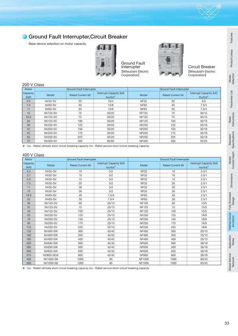
33
Base device selection on motor capacity.
Ground Fault Interrupter,Circuit Breaker
200 V Class
400 V Class
Ground Fault Interrupter【Mitsubishi Electric Corporation】
*:Icu:Rated ultimate short-circuit breaking capacity Ics:Rated service short-circuit breaking capacity
*:Icu:Rated ultimate short-circuit breaking capacity Ics:Rated service short-circuit breaking capacity
Circuit Breaker【Mitsubishi Electric Corporation】
Motor
Capacity(kW)
Ground Fault Interrupter Ground Fault Interrupter
Model Rated Current (A)Interrupt Capacity (kA)
Icu/Ics*Model Rated Current (A)
Interrupt Capacity (kA)
Icu/Ics*
5.5 NV32-SV 30 10/4 NF32 30 5/27.5 NV63-SV 40 15/8 NF63 40 7.5/411 NV63-SV 50 15/8 NF63 50 7.5/415 NV125-SV 75 50/25 NF125 75 30/15
18.5 NV125-SV 75 50/25 NF125 75 30/1522 NV125-SV 100 50/25 NF125 100 30/1530 NV250-SV 125 50/25 NF250 125 35/1837 NV250-SV 150 50/25 NF250 150 30/1845 NV250-SV 175 50/25 NF250 175 30/1855 NV250-SV 225 50/25 NF250 225 35/1875 NV400-SV 300 85/85 NF400 300 50/25
Motor
Capacity(kW)
Ground Fault Interrupter Ground Fault Interrupter
Model Rated Current (A)Interrupt Capacity (kA)
Icu/Ics*Model Rated Current (A)
Interrupt Capacity (kA)
Icu/Ics*
2.2 NV32-SV 10 5/2 NF32 10 2.5/13.7 NV32-SV 10 5/2 NF32 10 2.5/15.5 NV32-SV 15 5/2 NF32 15 2.5/17.5 NV32-SV 20 5/2 NF32 20 2.5/111 NV32-SV 30 5/2 NF32 30 2.5/115 NV32-SV 30 5/2 NF32 30 2.5/1
18.5 NV63-SV 40 7.5/4 NF63 40 2.5/122 NV63-SV 50 7.5/4 NF63 50 2.5/130 NV125-SV 60 25/13 NF125 60 10/537 NV125-SV 75 25/13 NF125 75 10/545 NV125-SV 100 25/13 NF125 100 10/555 NV250-SV 125 25/13 NF250 125 18/975 NV250-SV 150 25/13 NF250 150 18/990 NV250-SV 175 25/13 NF250 175 18/9
110 NV250-SV 225 25/13 NF250 225 18/9132 NV400-SW 300 42/42 NF400 300 25/13160 NV400-SW 350 42/42 NF400 350 25/13185 NV400-SW 400 42/42 NF400 400 25/13220 NV630-SW 500 42/42 NF630 500 36/18260 NV630-SW 500 42/42 NF630 500 36/18300 NV630-SW 630 42/42 NF630 630 36/18375 NV800-SEW 800 42/42 NF800 800 36/18450 NV1000-SB 1000 85 NF1000 1000 85/43500 NV1000-SB 1000 85 NF1000 1000 85/43
Feat
ures
Pro
duct
Lin
eup
Mod
el
Sel
ectio
nP
aram
eter
Lis
tB
asic
In
stru
ctio
nsS
tand
ard
S
pec
ifi ca
tions
Stan
dard
Co
nnec
tion
Diag
ram
Dim
ensi
ons
Fully
- Enc
lose
d
Des
ign
Perip
hera
l Dev
ices
an
d O
ptio
nsA
pp
licat
ion
Not
esG
lob
al S
ervi
ce
Net
wor
kPe
riphe
ral D
evic
es
and
Opt
ions
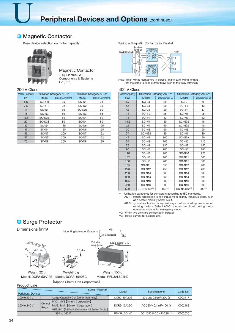
34
Peripheral Devices and Options (continued)
Lead cable: 250Lead cable: 910
Mounting hole specifications2-3 tapped
2-4 dia.mtg. hole
30
2416
36
7
9
22.5
30 16
34
68
76
2633
Model: DCR2-50A22E Model: DCR2-10A25C Model: RFN3AL504KDWeight: 22 g Weight: 5 g Weight: 150 g
0.8 dia.4.8 dia.
18 dia.
Magnetic Contactor【Fuji Electric FA Components & Systems Co., Ltd】
【Nippon Chemi-Con Corporation】
Base device selection on motor capacity.
Magnetic Contactor
200 V ClassMotor Capacity
(kW)Utilization Category AC-1*1 Utilization Category AC-3*1
Model Rated Current (A) Model Rated Current (A)
5.5 SC-4-0 25 SC-N1 267.5 SC-4-1 32 SC-N2 3511 SC-N1 50 SC-N2S 5015 SC-N2 60 SC-N3 65
18.5 SC-N2S 80 SC-N4 8022 SC-N2S 80 SC-N4 8030 SC-N4 135 SC-N6 12537 SC-N4 135 SC-N6 12545 SC-N7 200 SC-N7 15255 SC-N7 200 SC-N7 15275 SC-N8 260 SC-N8 180
Motor Capacity (kW)
Utilization Category AC-1*1 Utilization Category AC-3*1
Model Rated Current (A) Model Rated Current (A)
3.7 SC-03 20 SC-0 95.5 SC-03 20 SC-4-0 137.5 SC-03 20 SC-4-1 1711 SC-4-0 25 SC-N1 2515 SC-4-1 32 SC-N2 32
18.5 SC-N1 50 SC-N2S 4822 SC-N1 50 SC-N2S 4830 SC-N2 60 SC-N3 6537 SC-N2S 80 SC-N4 8045 SC-N3 100 SC-N5A 9055 SC-N3 100 SC-N6 11075 SC-N4 135 SC-N7 15090 SC-N7 200 SC-N8 180
110 SC-N7 200 SC-N10 220132 SC-N8 260 SC-N11 300160 SC-N8 260 SC-N11 300185 SC-N11 350 SC-N12 400220 SC-N12 450 SC-N12 400260 SC-N14 660 SC-N14 600300 SC-N14 660 SC-N14 600375 SC-N16 800 SC-N16 800450 SC-N16 800 SC-N16 800500 SC-N12×2*2 450*3 SC-N14×2*2 600*3
400 V Class
Dimensions (mm)
Surge Protector
1(R)2(S)3(T)
4(U)5(V)6(W)
1(R)2(S)3(T)
4(U)5(V)6(W)
ELCB or MCCBMagnetic
Contactor 1
MagneticContactor 2
JunctionTerminal
R1
S1
T1T/L3
S/L2
R/L1
U1000
Wiring a Magnetic Contactor in Parallel
Note: When wiring contactors in parallel, make sure wiring lengths are the same to keep current fl ow even to the relay terminals.
Product Line Surge Protector
Peripheral DevicesModel Specifi cations Code No.
200 to 230 V Large-Capacity Coil (other than relay) DCR2-50A22E 220 Vac 0.5 μ F+200 Ω C002417
200 to 240 VControl
Relay
MY2,MY3【Omron Corporation】MM2,MM4【Omron Corporation】HH22,HH23【Fuji Electric FA Components & Systems Co., Ltd】
DCR2-10A25C AC 250 V 0.1 μ F+100 Ω C002482
380 to 480 V RFN3AL504KD DC 1000 V 0.5 μ F+220 Ω C002630
*1: Utilization categories for contactors according to IEC standards.AC-1 : Typical application is non-inductive or slightly inductive loads, such
as a heater. Nomally select AC-1.AC-3 : Typical application is squirrel cage motors: starting, switches off
running motors. Select AC-3 to open the circuit during motor operation, such as for emergency stops.
*2:When two units are connected in parallel.
*3:Rated current for a single unit.
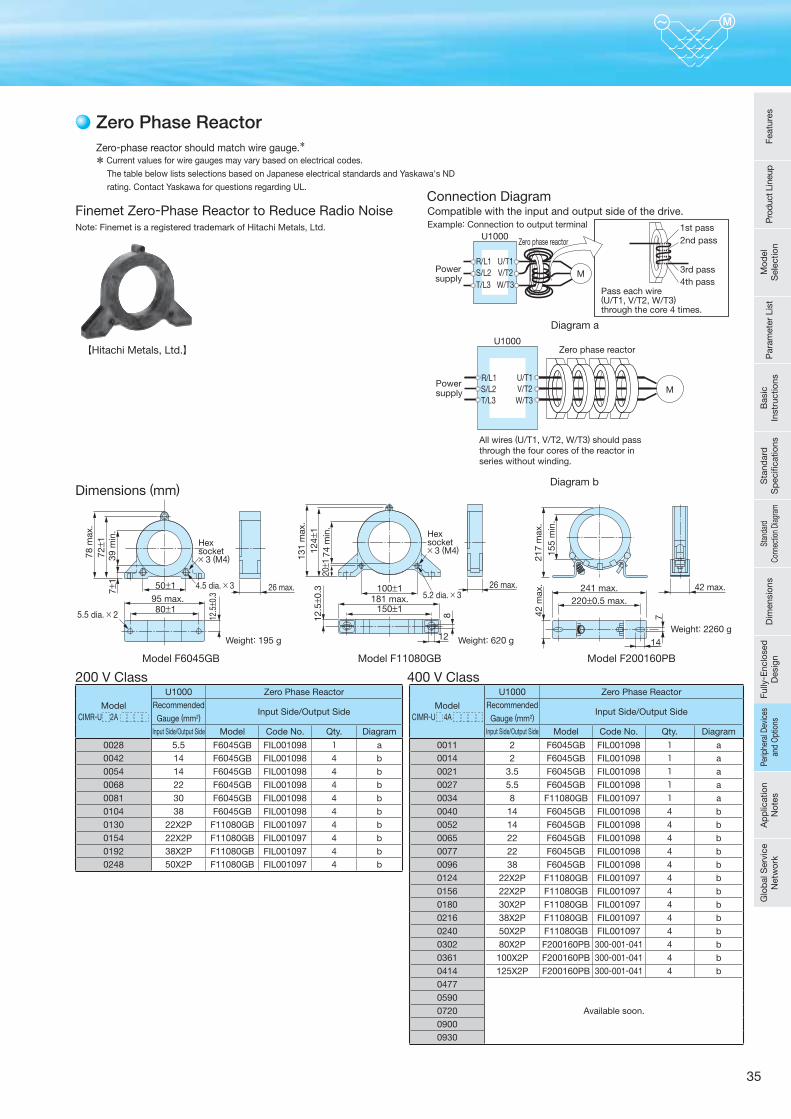
35
241 max.220±0.5 max.
217
max
.
155
min
.
42 max.
742 m
ax.
14
Zero-phase reactor should match wire gauge.*
* Current values for wire gauges may vary based on electrical codes. The table below lists selections based on Japanese electrical standards and Yaskawa's ND
rating. Contact Yaskawa for questions regarding UL.
Zero Phase Reactor
Finemet Zero-Phase Reactor to Reduce Radio NoiseNote: Finemet is a registered trademark of Hitachi Metals, Ltd. Example: Connection to output terminal
R/L1Powersupply
S/L2T/L3
U/T1
U1000
V/T2W/T3
Zero phase reactor
M
Pass each wire (U/T1, V/T2, W/T3)through the core 4 times.
1st pass2nd pass
3rd pass4th pass
Connection Diagram
Model F6045GB
78 m
ax.
39 m
in.
72± 1
7±1
12.5± 0
.3
50±1
80±195 max.
26 max.
Hexsocket× 3 (M4)
4.5 dia. × 3
5.5 dia. × 2
131
max
.
74 m
in.
124±
112
.5± 0
.320± 1
26 max.100±1181 max.
150±1
Hexsocket× 3 (M4)
8
12
5.2 dia. × 3
Dimensions (mm)
Weight: 195 g Weight: 620 g
Model F11080GB
Diagram a
【Hitachi Metals, Ltd.】
ModelCIMR-U 2A
U1000 Zero Phase ReactorRecommended
Gauge (mm2)Input Side/Output Side
Input Side/Output Side Model Code No. Qty. Diagram
0028 5.5 F6045GB FIL001098 1 a
0042 14 F6045GB FIL001098 4 b
0054 14 F6045GB FIL001098 4 b
0068 22 F6045GB FIL001098 4 b
0081 30 F6045GB FIL001098 4 b
0104 38 F6045GB FIL001098 4 b
0130 22X2P F11080GB FIL001097 4 b
0154 22X2P F11080GB FIL001097 4 b
0192 38X2P F11080GB FIL001097 4 b0248 50X2P F11080GB FIL001097 4 b
ModelCIMR-U 4A
U1000 Zero Phase ReactorRecommended
Gauge (mm2)Input Side/Output Side
Input Side/Output Side Model Code No. Qty. Diagram
0011 2 F6045GB FIL001098 1 a
0014 2 F6045GB FIL001098 1 a
0021 3.5 F6045GB FIL001098 1 a
0027 5.5 F6045GB FIL001098 1 a
0034 8 F11080GB FIL001097 1 a
0040 14 F6045GB FIL001098 4 b
0052 14 F6045GB FIL001098 4 b
0065 22 F6045GB FIL001098 4 b
0077 22 F6045GB FIL001098 4 b
0096 38 F6045GB FIL001098 4 b
0124 22X2P F11080GB FIL001097 4 b
0156 22X2P F11080GB FIL001097 4 b
0180 30X2P F11080GB FIL001097 4 b
0216 38X2P F11080GB FIL001097 4 b
0240 50X2P F11080GB FIL001097 4 b
0302 80X2P F200160PB 300-001-041 4 b
0361 100X2P F200160PB 300-001-041 4 b
0414 125X2P F200160PB 300-001-041 4 b
0477
Available soon.0590072009000930
200 V Class 400 V Class
Weight: 2260 g
Model F200160PB
Compatible with the input and output side of the drive.
Diagram b
MPowersupply
U1000
U/T1V/T2W/T3
R/L1S/L2T/L3
Zero phase reactor
All wires (U/T1, V/T2, W/T3) should passthrough the four cores of the reactor inseries without winding.
Feat
ures
Pro
duct
Lin
eup
Mod
el
Sel
ectio
nP
aram
eter
Lis
tB
asic
In
stru
ctio
nsS
tand
ard
S
pec
ifi ca
tions
Stan
dard
Co
nnec
tion
Diag
ram
Dim
ensi
ons
Fully
- Enc
lose
d
Des
ign
Perip
hera
l Dev
ices
an
d O
ptio
nsA
pp
licat
ion
Not
esG
lob
al S
ervi
ce
Net
wor
kPe
riphe
ral D
evic
es
and
Opt
ions
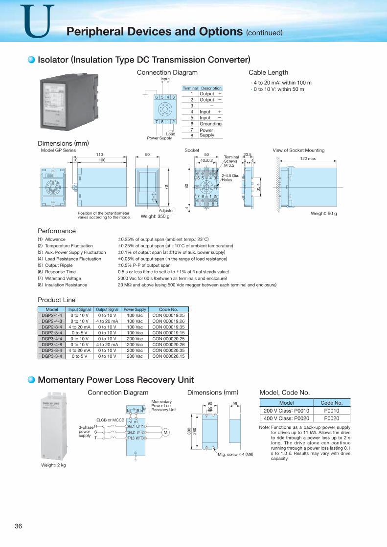
36
Peripheral Devices and Options (continued)
Isolator (Insulation Type DC Transmission Converter)
Momentary Power Loss Recovery Unit
M
R
S
T
R/L1S/L2T/L3
U/T1
B1/P
V/T2W/T3
E
ELCB or MCCB
Momentary Power Loss Recovery Unit
3-phasepowersupply
N
n1p1
Connection Diagram Dimensions (mm)
965090
300
280
Mtg. screw × 4 (M6)
Model Code No.
200 V Class: P0010 P0010400 V Class: P0020 P0020
Model, Code No.
Note: Functions as a back-up power supply for drives up to 11 kW. Allows the drive to ride through a power loss up to 2 s long. The drive alone can continue running through a power loss lasting 0.1 s to 1.0 s. Results may vary with drive capacity.
Weight: 2 kg
Cable LengthConnection Diagram
Dimensions (mm)
Model Input Signal Output Signal Power Supply Code No.DGP2-4-4 0 to 10 V 0 to 10 V 100 Vac CON 000019.25DGP2-4-8 0 to 10 V 4 to 20 mA 100 Vac CON 000019.26DGP2-8-4 4 to 20 mA 0 to 10 V 100 Vac CON 000019.35DGP2-3-4 0 to 5 V 0 to 10 V 100 Vac CON 000019.15DGP3-4-4 0 to 10 V 0 to 10 V 200 Vac CON 000020.25DGP3-4-8 0 to 10 V 4 to 20 mA 200 Vac CON 000020.26DGP3-8-4 4 to 20 mA 0 to 10 V 200 Vac CON 000020.35DGP3-3-4 0 to 5 V 0 to 10 V 200 Vac CON 000020.15
Product Line
Allowance ±0.25% of output span (ambient temp.: 23°C)
Temperature Fluctuation ±0.25% of output span (at ±10°C of ambient temperature)
Aux. Power Supply Fluctuation ±0.1% of output span (at ±10% of aux. power supply)
Load Resistance Fluctuation ±0.05% of output span (in the range of load resistance)
Output Ripple ±0.5% P-P of output span
Response Time 0.5 s or less (time to settle to ±1% of fi nal steady value)
Withstand Voltage 2000 Vac for 60 s (between all terminals and enclosure)
Insulation Resistance 20 MΩ and above (using 500 Vdc megger between each terminal and enclosure)
(1)
(2)
(3)(4)(5)(6)(7)(8)
Performance
12345678
TerminalOutput +Output - -Input +Input -GroundingPower Supply
Description
3456
2187
Power Supply
Input
Load
10010110 50
Adjuster
78
122 max
Model GP Series Socket View of Socket Mounting
Position of the potentiometervaries according to the model. Weight: 350 g
Weight: 60 g
TerminalScrewsM 3.5
50
80
35.4
4
40±0.2
6 5 4 3
7 8 1 2
23.55 4
2-4.5 Dia.Holes
4 to 20 mA: within 100 m0 to 10 V: within 50 m
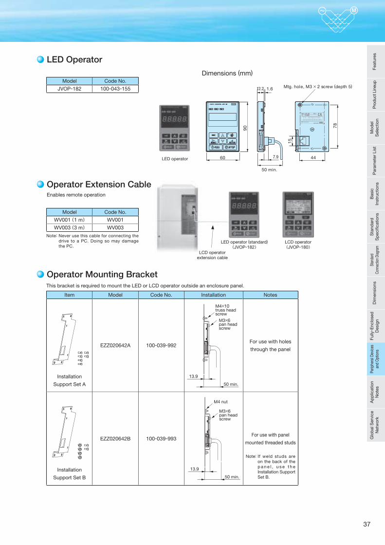
37
Dimensions (mm)
LED Operator
S / N : J007XE273710001
50 min.
Mtg. hole, M3 × 2 screw (depth 5)
90 78
60 7.9
12.2 1.6
44
15
Model Code No.
JVOP-182 100-043-155
Model Code No.
WV001(1 m) WV001
WV003(3 m) WV003
This bracket is required to mount the LED or LCD operator outside an enclosure panel.
Item Model Code No. Installation Notes
Installation
Support Set A
EZZ020642A 100-039-992For use with holes
through the panel
Installation
Support Set B
EZZ020642B 100-039-993For use with panel
mounted threaded studs
Note: If weld studs are on the back of the p a n e l , u s e t h e Installation Support Set B.
Operator Mounting Bracket
Enables remote operation
Operator Extension Cable
LED operator
LCD operator(JVOP-180)
LED operator (standard)(JVOP-182)
LCD operatorextension cable
Note: Never use this cable for connecting the drive to a PC. Doing so may damage the PC.
13.9
50 min.
M4×10truss headscrew
M3×6pan headscrew
13.9
50 min.
M3×6pan headscrew
M4 nut
Feat
ures
Pro
duct
Lin
eup
Mod
el
Sel
ectio
nP
aram
eter
Lis
tB
asic
In
stru
ctio
nsS
tand
ard
S
pec
ifi ca
tions
Stan
dard
Co
nnec
tion
Diag
ram
Dim
ensi
ons
Fully
- Enc
lose
d
Des
ign
Perip
hera
l Dev
ices
an
d O
ptio
nsA
pp
licat
ion
Not
esG
lob
al S
ervi
ce
Net
wor
kPe
riphe
ral D
evic
es
and
Opt
ions
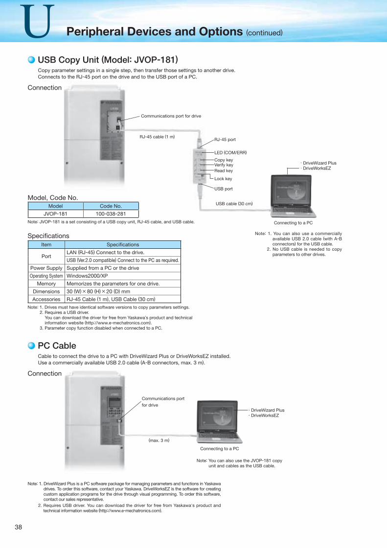
38
Peripheral Devices and Options (continued)
USB Copy Unit (Model: JVOP-181)
Model, Code No.Model Code No.
JVOP-181 100-038-281
Item Specifi cations
PortLAN (RJ-45) Connect to the drive.
USB (Ver.2.0 compatible) Connect to the PC as required.
Power Supply Supplied from a PC or the drive
Operating System Windows2000/XP
Memory Memorizes the parameters for one drive.
Dimensions 30 (W)×80 (H)×20 (D) mm
Accessories RJ-45 Cable (1 m), USB Cable (30 cm)
Specifi cations
Note: 1. Drives must have identical software versions to copy parameters settings.2. Requires a USB driver.
You can download the driver for free from Yaskawa’s product and technical information website (http://www.e-mechatronics.com).
3. Parameter copy function disabled when connected to a PC.
Note: JVOP-181 is a set consisting of a USB copy unit, RJ-45 cable, and USB cable.
Connection
RJ-45 cable (1 m)
LED (COM/ERR)
Copy keyVerify keyRead key
USB port
USB cable (30 cm)
RJ-45 port
Lock key
Communications port for drive
· DriveWizard Plus· DriveWorksEZ
・DriveWizard Plus・DriveWorksEZ
Connecting to a PC
Copy parameter settings in a single step, then transfer those settings to another drive. Connects to the RJ-45 port on the drive and to the USB port of a PC.
Note: 1. You can also use a commercially available USB 2.0 cable (with A-B connectors) for the USB cable.
2. No USB cable is needed to copy parameters to other drives.
(max. 3 m)
PC Cable
Connection
Cable to connect the drive to a PC with DriveWizard Plus or DriveWorksEZ installed.Use a commercially available USB 2.0 cable (A-B connectors, max. 3 m).
Connecting to a PC
Note: You can also use the JVOP-181 copy unit and cables as the USB cable.
Communications port
for drive
Note: 1. DriveWizard Plus is a PC software package for managing parameters and functions in Yaskawa drives. To order this software, contact your Yaskawa. DriveWorksEZ is the software for creating custom application programs for the drive through visual programming. To order this software, contact our sales representative.
2. Requires USB driver. You can download the driver for free from Yaskawa's product and technical information website (http://www.e-mechatronics.com).
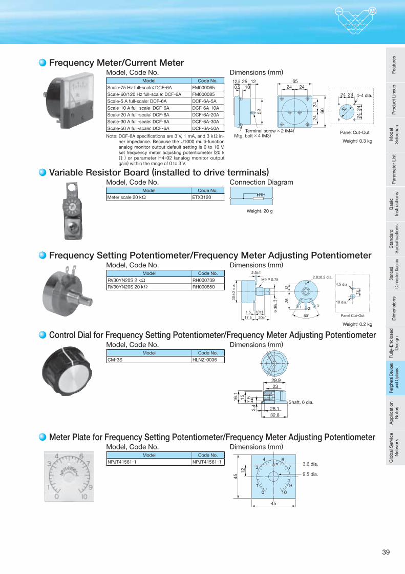
39
Variable Resistor Board (installed to drive terminals)
Model Code No.
Meter scale 20 kΩ ETX3120
Model, Code No. Connection Diagram
RH
Weight: 20 g
Frequency Meter/Current Meter
Model Code No.
Scale-75 Hz full-scale: DCF-6A FM000065Scale-60/120 Hz full-scale: DCF-6A FM000085Scale-5 A full-scale: DCF-6A DCF-6A-5A
Scale-10 A full-scale: DCF-6A DCF-6A-10A
Scale-20 A full-scale: DCF-6A DCF-6A-20A
Scale-30 A full-scale: DCF-6A DCF-6A-30A
Scale-50 A full-scale: DCF-6A DCF-6A-50A
Model, Code No. Dimensions (mm)
Panel Cut-Out
52
2424
2424
2424
60
2424122512.5
0.5 1065
53
4-4 dia.
Terminal screw × 2 (M4)Mtg. bolt × 4 (M3)Note: DCF-6A specifications are 3 V, 1 mA, and 3 kΩ in-
ner impedance. Because the U1000 multi-function analog monitor output default setting is 0 to 10 V, set frequency meter adjusting potentiometer (20 kΩ ) or parameter H4-02 (analog monitor output gain) within the range of 0 to 3 V.
Frequency Setting Potentiometer/Frequency Meter Adjusting PotentiometerModel, Code No. Dimensions (mm)
Panel Cut-Out
1 2
60˚
3
10±1
20±1
30±
2 d
ia.
M9 P 0.75
12
1225
17.51.5
10 dia.
4.5 dia
2.8±0.2 dia.2.5±1
6 d
ia.+
0 − 0.1
Model Code No.
RV30YN20S 2 kΩ RH000739RV30YN20S 20 kΩ RH000850
Control Dial for Frequency Setting Potentiometer/Frequency Meter Adjusting PotentiometerModel, Code No. Dimensions (mm)
29.923
32.826.1
16.1
157.
53.
4
Shaft, 6 dia.
Model Code No.
CM-3S HLNZ-0036
Meter Plate for Frequency Setting Potentiometer/Frequency Meter Adjusting PotentiometerModel, Code No. Dimensions (mm)
01
3
4 6
7
910
45
45
12
3.6 dia.
9.5 dia.
Model Code No.
NPJT41561-1 NPJT41561-1
Weight: 0.3 kg
Weight: 0.2 kg
Feat
ures
Pro
duct
Lin
eup
Mod
el
Sel
ectio
nP
aram
eter
Lis
tB
asic
In
stru
ctio
nsS
tand
ard
S
pec
ifi ca
tions
Stan
dard
Co
nnec
tion
Diag
ram
Dim
ensi
ons
Fully
- Enc
lose
d
Des
ign
Perip
hera
l Dev
ices
an
d O
ptio
nsA
pp
licat
ion
Not
esG
lob
al S
ervi
ce
Net
wor
kPe
riphe
ral D
evic
es
and
Opt
ions
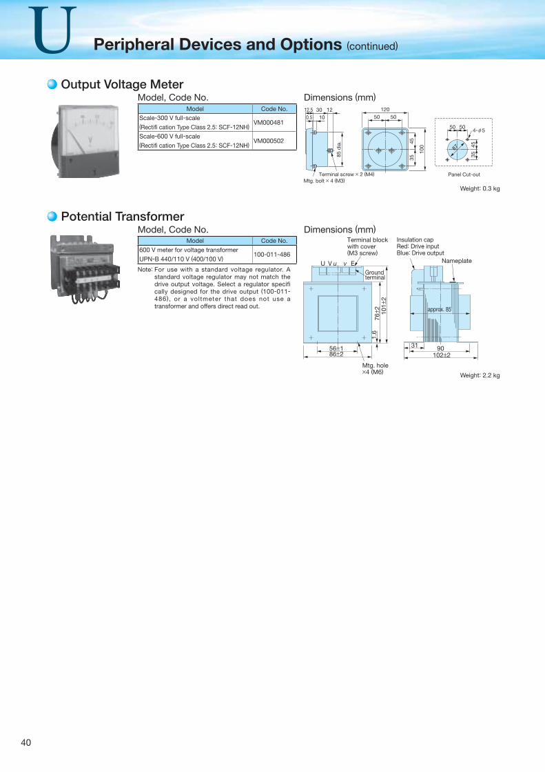
40
Peripheral Devices and Options (continued)
Potential Transformer
Model Code No.
600 V meter for voltage transformer
UPN-B 440/110 V (400/100 V)100-011-486
Model, Code No. Dimensions (mm)Insulation capRed: Drive inputBlue: Drive output
Mtg. hole×4 (M6)
102±2
approx. 85
31 9086±256±1
Nameplate
101±
276± 2
1.6
Groundterminal
Terminal blockwith cover(M3 screw)
U V u v ENote: For use with a standard voltage regulator. A
standard voltage regulator may not match the drive output voltage. Select a regulator specifi cally designed for the drive output (100-011-486), or a voltmeter that does not use a transformer and offers direct read out.
Weight: 2.2 kg
Output Voltage MeterModel, Code No. Dimensions (mm)
Panel Cut-out
85 d
ia. 45
35
4535
5050
100
5050123012.5
0.5 10
120
87
4- 5
Terminal screw × 2 (M4)Mtg. bolt × 4 (M3)
ϕ
Model Code No.
Scale-300 V full-scale(Rectifi cation Type Class 2.5: SCF-12NH)
VM000481
Scale-600 V full-scale (Rectifi cation Type Class 2.5: SCF-12NH)
VM000502
Weight: 0.3 kg
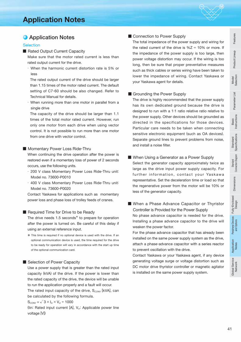
41
Application Notes
Application Notes
Selection
Rated Output Current CapacityMake sure that the motor rated current is less than
rated output current for the drive.
· When the harmonic current distortion rate is 5% or
less
The rated output current of the drive should be larger
than 1.15 times of the motor rated current. The default
setting of C7-60 should be also changed. Refer to
Technical Manual for details.
· When running more than one motor in parallel from a
single drive
The capacity of the drive should be larger than 1.1
times of the total motor rated current. However, run
only one motor from each drive when using vector
control. It is not possible to run more than one motor
from one drive with vector control.
Momentary Power Loss Ride-ThruWhen continuing the drive operation after the power is
restored even if a momentary loss of power of 2 seconds
occurs, use the following units.
· 200 V class Momentary Power Loss Ride-Thru unit:
Model no. 73600-P0010
· 400 V class Momentary Power Loss Ride-Thru unit:
Model no. 73600-P0020
Contact Yaskawa for applications such as momentary
power loss and phase loss of trolley feeds of cranes.
Required Time for Drive to be ReadyThe drive needs 1.5 seconds* to prepare for operation
after the power is turned on. Be careful of this delay if
using an external reference input.
* This time is required if no optional device is used with the drive. If an
optional communication device is used, the time required for the drive
to be ready for operation will vary in accordance with the start up time
of the optional communication card.
Selection of Power CapacityUse a power supply that is greater than the rated input
capacity (kVA) of the drive. If the power is lower than
the rated capacity of the drive, the device will be unable
to run the application properly and a fault will occur.
The rated input capacity of the drive, SCONV [kVA], can
be calculated by the following formula.
SCONV = √3 × Iin × Vin ÷ 1000(Iin: Rated input current [A], Vin: Applicable power line
voltage [V])
■ Connection to Power SupplyThe total impedance of the power supply and wiring for
the rated current of the drive is %Z = 10% or more. If
the impedance of the power supply is too large, then
power voltage distortion may occur. If the wiring is too
long, then be sure that proper preventative measures
such as thick cables or series wiring have been taken to
lower the impedance of wiring. Contact Yaskawa or
your Yaskawa agent for details.
■ Grounding the Power SupplyThe drive is highly recommended that the power supply
has its own dedicated ground because the drive is
designed to run with a 1:1 ratio relative ratio relative to
the power supply. Other devices should be grounded as
directed in the specifications for those devices.
Particular care needs to be taken when connecting
sensitive electronic equipment (such as OA devices).
Separate ground lines to prevent problems from noise,
and install a noise fi lter.
When Using a Generator as a Power SupplySelect the generator capacity approximately twice as
large as the drive input power supply capacity. For
f u r t h e r i n f o r m a t i o n , c o n t a c t y o u r Ya s k a w a
representative. Set the deceleration time or load so that
the regenerative power from the motor will be 10% or
less of the generator capacity.
When a Phase Advance Capacitor or Thyristor
Controller is Provided for the Power SupplyNo phase advance capacitor is needed for the drive.
Installing a phase advance capacitor to the drive will
weaken the power factor.
For the phase advance capacitor that has already been
installed on the same power supply system as the drive,
attach a phase-advance capacitor with a series reactor
to prevent oscillation with the drive.
Contact Yaskawa or your Yaskawa agent, if any device
generating voltage surge or voltage distortion such as
DC motor drive thyristor controller or magnetic agitator
is installed on the same power supply system.
Feat
ures
Pro
duct
Lin
eup
Mod
el
Sel
ectio
nP
aram
eter
Lis
tB
asic
In
stru
ctio
nsS
tand
ard
S
pec
ifi ca
tions
Stan
dard
Co
nnec
tion
Diag
ram
Dim
ensi
ons
Fully
- Enc
lose
d
Des
ign
Perip
hera
l Dev
ices
an
d O
ptio
nsA
pp
licat
ion
Not
esG
lob
al S
ervi
ce
Net
wor
kA
pp
licat
ion
Not
esPe
riphe
ral D
evic
es
and
Opt
ions
42
Application Notes (continued)
Prevention Against EMC or Harmonic Leakage CurrentUse units with built-in EMC filters that have the CE
marking.
If a device that will be affected by noise is near the
drive, use a zero-phase reactor as a noise fi lter.
Use a leakage relay or a ground leakage breaker
designed for products provided with prevention from
harmonics leak current, when necessary.
Affects of Power Supply DistortionWhen the power supply voltage is distorted, the
harmonics contents increase because the harmonics of
the power supply system enter the drive.
Starting TorqueThe overload rating for the drive determines the starting
and accelerating characteristics of the motor. Expect
lower torque than when running from line power. To
achieve a higher starting torque, use a larger drive, or a
drive and motor with larger capacity.
Emergency StopWhen the drive faults out, the output is shut off. This,
however, does not stop the motor immediately. Some
type of mechanical brake may be needed if it is
necessary to halt the motor faster than the Fast Stop
function is able to.
Repetitive Starting/StoppingCranes (hoists), elevators, punching presses, and other
such applications with frequent starts and stops often
exceed 150% of their rated current values. Heat stress
generated from repetitive high current can shorten the
lifespan of the IGBTs. The expected lifespan for the
IGBTs is about 8 million start and stop cycles with a 4
kHz carrier frequency and a 150% peak current.
For crane-type applications using an inching function in
which the motor is quickly started and stopped,
Yaskawa recommends selecting a large enough drive
so that peak current levels remain below 150% of the
drive rated current.
Run only one motor from each drive when using vector
control. It is not possible to run more than one motor
from one drive with vector control.
Carrier Frequency DeratingWhen the carrier frequency of the drive is increased
above the factory default setting, the rated output current
of the drive should be reduced. Refer to the instruction
manual of the drive for details on this function.
Installation
Enclosure PanelsKeep the drive in a clean environment by either
selecting an area free of airborne dust, lint, and oil mist,
or install the drive in an enclosure panel. Leave the
required space between the drives to provide for
cooling, and take steps to ensure that the ambient
temperature remains within allowable limits. Keep
flammable materials away from the drive. If the drive
must be used in an area where it is subjected to oil mist
and excessive vibration, protective designs are
available. Contact Yaskawa or your Yaskawa agent for
details.
Installation DirectionThe drive should be installed upright as specifi ed in the
manual.
Settings
Motor CodeIf using permanent magnet motors, make sure that the
proper motor code has been set to parameter E5-01
before performing a trial run.
Upper LimitsThe drive is capable of running the motor up to 400 Hz.
Due to the danger of accidentally of operating at high
speed, be sure to set the upper limit for the frequency
to control the maximum speed. The default setting for
the maximum output frequency is 60 Hz.
DC Injection BrakingMotor overheat can result if there is too much current
used during DC Injection Braking, or if the time for DC
Injection Braking is too long.
Acceleration/Deceleration TimesAcceleration and deceleration times are affected by
how much torque the motor generates, the load torque,
and the inertia moment. Set a longer accel/decel time
when Stall Prevention is enabled. The accel/decel times
are lengthened for as long as the Stall Prevention
function is operating. For faster acceleration and
deceleration, use a larger drive and motor.
43
Compliance with Harmonic Suppression Guidelines· Guidelines for harmonic suppression measures are
applicable to consumers that receive power from a 6.6 kV
or higher system. For details, refer to the Harmonics
Suppression Technical Guideline JEAG 9702-1995.
· With respect to the harmonic suppression guidelines, the
U1000 is a Matrix Converter and does not generate
harmonics (K5=0). However, the harmonic component is
not completely zero.
General Handling
Wiring CheckDoing so will destroy the drive.
Be sure to perform a fi nal check of all sequence wiring
and other connections before turning the power on.
Make sure there are no short circuits on the control
terminals (+V, AC,etc.), as this could damage the drive.
Installing a Ground Fault Interrupter or an MCCBWe recommend that you install ground fault interrupter (ELCB) for wire protection and as protection against
secondary damage for faults. Also, if short circuit cutoffs
are permitted in the upstream power supply system, we
recommend that you use a molded case circuit breaker (MCCB).
We recommend that you select an ELCB designed for
AC drives (one with high-frequency countermeasures).
Select the MCCB based on the power supply power
factor of the Matrix Converter (depends on the power
supply voltage, output frequency, and load).
Magnetic Contactor InstallationUse a magnetic contactor (MC) to ensure that power to
the drive can be completely shut off when necessary.
The MC should be wired so that it opens when a fault
output terminal is triggered.
Avoid switching a magnetic contactor on the power
supply side more frequently than once every 30 minutes.
Frequent switching can cause damage to the drive.
Inspection and MaintenanceCapacitors for the control power supply take time to
discharge even after the power has been shut off. After
shutting off the power, wait for at least the amount of
t ime specified on the drive before touching any
components.
The heatsink can become quite hot during operation,
and proper precautions should be taken to prevent
burns. When replacing the cooling fan, shut off the
power and wait at least 15 minutes to be sure that the
heatsink has cooled down.
Even when the power has been shut off for a drive
running a PM motor, voltage continues to be generated
at the motor terminals while the motor coasts to stop.
Take the precautions described below to prevent shock
and injury:
· Applications where the machine can still rotate even
though the drive has fully stopped should have a load
switch installed to the output side of the drive. Yaskawa
recommends manual load switches from the AICUT LB
Series by AICHI Electric Works Co., Ltd.
· Do not allow an external force to rotate the motor
beyond the maximum allowable speed, also when the
drive has been shut off.
· Wait for at least the time specifi ed on the warning label
after opening the load switch on the output side before
inspecting the drive or performing any maintenance.
· Do not open and close the load switch while the motor
is running, as this can damage the drive.
· If the motor is coasting, make sure the power to the
drive is turned on and the drive output has completely
stopped before closing the load switch.
WiringAll wire ends should use ring terminals for UL/cUL
compliance. Use only the tools recommended by the
terminal manufacturer for crimping.
Transporting the DriveNever steam clean the drive.
During transport, keep the drive from coming into
contact with salts, fl uorine, bromine, phthalate ester, and
other such harmful chemicals.
Feat
ures
Pro
duct
Lin
eup
Mod
el
Sel
ectio
nP
aram
eter
Lis
tB
asic
In
stru
ctio
nsS
tand
ard
S
pec
ifi ca
tions
Stan
dard
Co
nnec
tion
Diag
ram
Dim
ensi
ons
Fully
- Enc
lose
d
Des
ign
Perip
hera
l Dev
ices
an
d O
ptio
nsA
pp
licat
ion
Not
esG
lob
al S
ervi
ce
Net
wor
kA
pp
licat
ion
Not
es
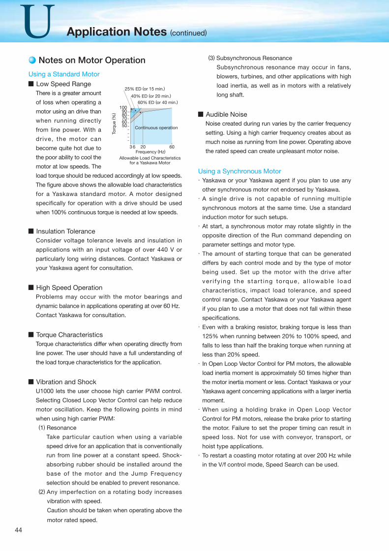
44
Application Notes (continued)
Notes on Motor Operation
Using a Standard Motor
Low Speed RangeThere is a greater amount
of loss when operating a
motor using an drive than
when running directly
from line power. With a
dr ive, the motor can
become quite hot due to
the poor ability to cool the
motor at low speeds. The
load torque should be reduced accordingly at low speeds.
The fi gure above shows the allowable load characteristics
for a Yaskawa standard motor. A motor designed
specifically for operation with a drive should be used
when 100% continuous torque is needed at low speeds.
Insulation ToleranceConsider voltage tolerance levels and insulation in
applications with an input voltage of over 440 V or
particularly long wiring distances. Contact Yaskawa or
your Yaskawa agent for consultation.
High Speed OperationProblems may occur with the motor bearings and
dynamic balance in applications operating at over 60 Hz.
Contact Yaskawa for consultation.
Torque CharacteristicsTorque characteristics differ when operating directly from
line power. The user should have a full understanding of
the load torque characteristics for the application.
Vibration and ShockU1000 lets the user choose high carrier PWM control.
Selecting Closed Loop Vector Control can help reduce
motor oscillation. Keep the following points in mind
when using high carrier PWM:
(1) Resonance
Take particular caution when using a variable
speed drive for an application that is conventionally
run from line power at a constant speed. Shock-
absorbing rubber should be installed around the
base of the motor and the Jump Frequency
selection should be enabled to prevent resonance.(2) Any imperfection on a rotating body increases
vibration with speed.
Caution should be taken when operating above the
motor rated speed.
(3) Subsynchronous Resonance
Subsynchronous resonance may occur in fans,
blowers, turbines, and other applications with high
load inertia, as well as in motors with a relatively
long shaft.
Audible NoiseNoise created during run varies by the carrier frequency
setting. Using a high carrier frequency creates about as
much noise as running from line power. Operating above
the rated speed can create unpleasant motor noise.
Using a Synchronous Motor· Yaskawa or your Yaskawa agent if you plan to use any
other synchronous motor not endorsed by Yaskawa.
· A single drive is not capable of running multiple
synchronous motors at the same time. Use a standard
induction motor for such setups.
· At start, a synchronous motor may rotate slightly in the
opposite direction of the Run command depending on
parameter settings and motor type.
· The amount of starting torque that can be generated
differs by each control mode and by the type of motor
being used. Set up the motor with the drive after
ve r i f y ing the s ta r t ing to rque , a l lowab le load
characteristics, impact load tolerance, and speed
control range. Contact Yaskawa or your Yaskawa agent
if you plan to use a motor that does not fall within these
specifi cations.
· Even with a braking resistor, braking torque is less than
125% when running between 20% to 100% speed, and
falls to less than half the braking torque when running at
less than 20% speed.
· In Open Loop Vector Control for PM motors, the allowable
load inertia moment is approximately 50 times higher than
the motor inertia moment or less. Contact Yaskawa or your
Yaskawa agent concerning applications with a larger inertia
moment.
· When using a holding brake in Open Loop Vector
Control for PM motors, release the brake prior to starting
the motor. Failure to set the proper timing can result in
speed loss. Not for use with conveyor, transport, or
hoist type applications.
· To restart a coasting motor rotating at over 200 Hz while
in the V/f control mode, Speed Search can be used.
50
3 6 20 60
60708090
100
25% ED (or 15 min.)
40% ED (or 20 min.)
60% ED (or 40 min.)
Allowable Load Characteristicsfor a Yaskawa Motor
Frequency (Hz)
Continuous operation
Torq
ue ( %
)
45
Applications with Specialized Motors
Multi-Pole MotorBecause the rated current will differ from a standard
motor, be sure to check the maximum current when
selecting a drive. Always stop the motor before
switching between the number of motor poles. If a
regenerative overvoltage fault occurs or if overcurrent
protection is triggered, the motor will coast to stop.
Submersible MotorBecause motor rated current is greater than a standard
motor, select the drive capacity accordingly. Be sure to
use a large enough motor cable to avoid decreasing the
maximum torque level on account of voltage drop
caused by a long motor cable.
Explosion-Proof MotorBoth the motor and drive need to be tested together to
be certified as explosion-proof. The drive is not for
explosion proof areas.
An explosion-proof pulse generators (PG) is used for an
explosion-proof with voltage tolerance. Use a specially
designed pulse coupler between the drive and the PG
when wiring.
Geared MotorContinuous operation specifications differ by the
manufacturer of the lubricant. Due to potential problems
of gear damage when operating at low speeds, be sure
to select the proper lubricant. Consult with the
manufacturer for applications that require speeds
greater than the rated speed range of the motor or gear
box.
Single-Phase MotorVariable speed drives are not designed for operating
single phase motors. Using a capacitor to start the
motor causes excessive current to flow into the
capacitors, potentially causing damage. A split-phase
start or a repulsion start can end up burning out the
starter coils because the internal centrifugal switch is
not activated. U1000 is for use only with 3-phase
motors.
Motor with BrakeCaution should be taken when using a drive to operate a
motor with a built-in holding brake. If the brake is
connected to the output side of the drive, it may not
release at start due to low voltage levels. A separate
power supply should be installed for the motor brake.
Motors with a built-in brake tend to generate a fair amount
of noise when running at low speeds.
Power Driven Machinery (decelerators, belts, chains, etc.)
Continuous operation at low speeds wears on the
lubricating material used in gear box type systems to
accelerate and decelerate power driven machinery.
Caution should also be taken when operating at speeds
above the rated machine speed due to noise and
shortened performance life.
Feat
ures
Pro
duct
Lin
eup
Mod
el
Sel
ectio
nP
aram
eter
Lis
tB
asic
In
stru
ctio
nsS
tand
ard
S
pec
ifi ca
tions
Stan
dard
Co
nnec
tion
Diag
ram
Dim
ensi
ons
Fully
- Enc
lose
d
Des
ign
Perip
hera
l Dev
ices
an
d O
ptio
nsA
pp
licat
ion
Not
esG
lob
al S
ervi
ce
Net
wor
kA
pp
licat
ion
Not
es

46
MEMO
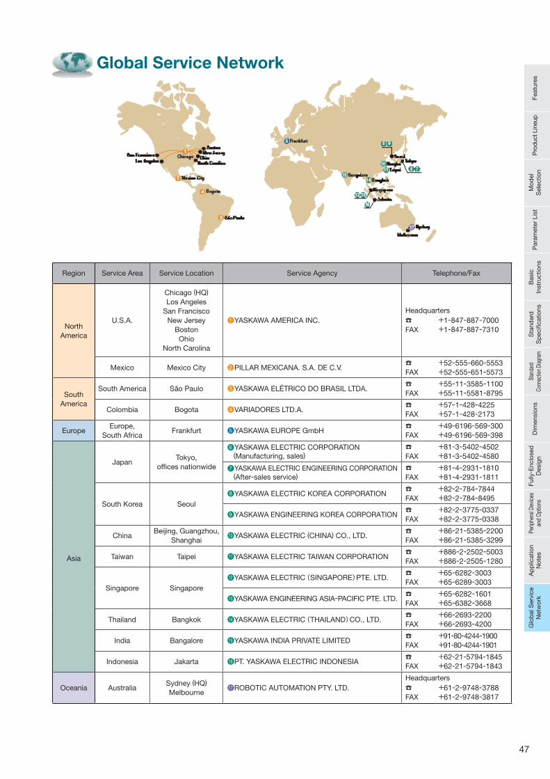
47
Global Service Network
Region Service Area Service Location Service Agency Telephone/Fax
North America
U.S.A.
Chicago (HQ)Los Angeles
San FranciscoNew Jersey
BostonOhio
North Carolina
●1 YASKAWA AMERICA INC.Headquarters☎ +1-847-887-7000FAX +1-847-887-7310
Mexico Mexico City ●2 PILLAR MEXICANA. S.A. DE C.V.☎ +52-555-660-5553FAX +52-555-651-5573
South America
South America Sao Paulo ●3 YASKAWA ELÉTRICO DO BRASIL LTDA.☎ +55-11-3585-1100FAX +55-11-5581-8795
Colombia Bogota ●4 VARIADORES LTD.A.☎ +57-1-428-4225FAX +57-1-428-2173
EuropeEurope,
South AfricaFrankfurt ●5 YASKAWA EUROPE GmbH
☎ +49-6196-569-300FAX +49-6196-569-398
Asia
JapanTokyo,
offi ces nationwide
●6 YASKAWA ELECTRIC CORPORATION (Manufacturing, sales)
☎ +81-3-5402-4502FAX +81-3-5402-4580
●7 YASKAWA ELECTRIC ENGINEERING CORPORATION (After-sales service)
☎ +81-4-2931-1810FAX +81-4-2931-1811
South Korea Seoul●8 YASKAWA ELECTRIC KOREA CORPORATION
☎ +82-2-784-7844FAX +82-2-784-8495
●9 YASKAWA ENGINEERING KOREA CORPORATION☎ +82-2-3775-0337FAX +82-2-3775-0338
ChinaBeijing, Guangzhou,
Shanghai●10 YASKAWA ELECTRIC (CHINA) CO., LTD.
☎ +86-21-5385-2200FAX +86-21-5385-3299
Taiwan Taipei ●11 YASKAWA ELECTRIC TAIWAN CORPORATION☎ +886-2-2502-5003FAX +886-2-2505-1280
Singapore Singapore●12 YASKAWA ELECTRIC(SINGAPORE)PTE. LTD.
☎ +65-6282-3003FAX +65-6289-3003
●13 YASKAWA ENGINEERING ASIA-PACIFIC PTE. LTD.☎ +65-6282-1601FAX +65-6382-3668
Thailand Bangkok ●14 YASKAWA ELECTRIC(THAILAND)CO., LTD.☎ +66-2693-2200FAX +66-2693-4200
India Bangalore ●15 YASKAWA INDIA PRIVATE LIMITED☎ +91-80-4244-1900FAX +91-80-4244-1901
Indonesia Jakarta ●16 PT. YASKAWA ELECTRIC INDONESIA☎ +62-21-5794-1845FAX +62-21-5794-1843
Oceania AustraliaSydney (HQ) Melbourne
●17 ROBOTIC AUTOMATION PTY. LTD.Headquarters☎ +61-2-9748-3788FAX +61-2-9748-3817
Feat
ures
Pro
duct
Lin
eup
Mod
el
Sel
ectio
nP
aram
eter
Lis
tB
asic
In
stru
ctio
nsS
tand
ard
S
pec
ifi ca
tions
Stan
dard
Co
nnec
tion
Diag
ram
Dim
ensi
ons
Fully
- Enc
lose
d
Des
ign
Perip
hera
l Dev
ices
an
d O
ptio
nsA
pp
licat
ion
Not
esG
lob
al S
ervi
ce
Net
wor
kG
lob
al S
ervi
ce
Net
wor
k
In the event that the end user of this product is to be the military and said product is to be employed in any weapons systems or the manufacture thereof, the export will fall under the relevant regulations as stipulated in the Foreign Exchange and Foreign Trade Regulations. Therefore, be sure to follow all procedures and submit all relevant documentation according to any and all rules, regulations and laws that may apply.
Specifications are subject to change without notice for ongoing product modifications and improvements.
© 2014 YASKAWA ELECTRIC CORPORATION. All rights reserved.
LITERATURE NO. KAEP C710636 02B
14-7-2
YASKAWA ELECTRIC CORPORATION
U1000
DRIVE CENTER (INVERTER PLANT)2-13-1, Nishimiyaichi, Yukuhashi, Fukuoka, 824-8511, JapanPhone 81-930-25-3844 Fax 81-930-25-4369http://www.yaskawa.co.jp
YASKAWA ELECTRIC CORPORATIONNew Pier Takeshiba South Tower, 1-16-1, Kaigan, Minatoku, Tokyo, 105-6891, JapanPhone 81-3-5402-4502 Fax 81-3-5402-4580http://www.yaskawa.co.jp
YASKAWA AMERICA, INC.2121 Norman Drive South, Waukegan, IL 60085, U.S.A.Phone 1-800-YASKAWA (927-5292) or 1-847-887-7000 Fax 1-847-887-7310http://www.yaskawa.com
YASKAWA ELÉTRICO DO BRASIL LTDA.Avenida Piraporinha 777, Diadema, São Paulo, 09950-000, BrazilPhone 55-11-3585-1100 Fax 55-11-3585-1187http://www.yaskawa.com.br
YASKAWA EUROPE GmbHHauptstrasse 185, 65760 Eschborn, GermanyPhone 49-6196-569-300 Fax 49-6196-569-398http://www.yaskawa.eu.com
YASKAWA ELECTRIC KOREA CORPORATION9F, Kyobo Securities Bldg., 26-4, Yeouido-dong, Yeongdeungpo-gu, Seoul, 150-737, KoreaPhone 82-2-784-7844 Fax 82-2-784-8495http://www.yaskawa.co.kr
YASKAWA ELECTRIC (SINGAPORE) PTE. LTD.151 Lorong Chuan, #04-02A, New Tech Park 556741, SingaporePhone 65-6282-3003 Fax 65-6289-3003http://www.yaskawa.com.sg
YASKAWA ELECTRIC (CHINA) CO., LTD.22F, One Corporate Avenue, No.222 Hubin Road, Huangpu District, Shanghai 200021, ChinaPhone 86-21-5385-2200 Fax 86-21-5385-3299http://www.yaskawa.com.cn
YASKAWA ELECTRIC (CHINA) CO., LTD. BEIJING OFFICERoom 1011, Tower W3 Oriental Plaza, No.1 East Chang An Ave.,Dong Cheng District, Beijing, 100738, ChinaPhone 86-10-8518-4086 Fax 86-10-8518-4082
YASKAWA ELECTRIC TAIWAN CORPORATION9F, 16, Nanking E. Rd., Sec. 3, Taipei, 104, TaiwanPhone 886-2-2502-5003 Fax 886-2-2505-1280http://www.yaskawa-taiwan.com.tw
YASKAWA INDIA PRIVATE LIMITED#17/A Electronics City, Hosur Road Bangalore 560 100 (Karnataka), IndiaPhone 91-80-4244-1900 Fax 91-80-4244-1901http://www.yaskawaindia.in
Published in Japan September 2014 14-06 -01


