Low Level Gigabit Ethernet Analysis for the LHCb Computing Farm Public Note Issue: 1 Revision: 1 Reference: LHCb-2005-091 Created: September 5, 2005 Last modified: August 22, 2006 Prepared by: Cedric Walravens, Benjamin Gaidioz
Transcript
Low Level Gigabit EthernetAnalysis for the LHCbComputing Farm
Public NoteIssue: 1Revision: 1
Reference: LHCb-2005-091Created: September 5, 2005Last modified: August 22, 2006
Prepared by: Cedric Walravens, Benjamin Gaidioz
Low Level Gigabit Ethernet Analysis for the LHCb Computing F arm Ref: LHCb-2005-091Public Note Issue: 1
Date: August 22, 2006
Abstract
This note presents the concept of Receive Descriptor Recycling to significantly reduce the performancedrop associated with small packet Gigabit Ethernet traffic. High reliability of small-sized transmis-sions is crucial for correct calibration runs of the LHCb experiment, at the CERN LHC accelerator.Previous work [1] applied to full link load Ethernet traffic, using UDP processes. This work coversmore low-level details of the performance problem for small-sized traffic, using more lower-level Eth-ernet frames, and, with a deeper analysis at the PCI/PCI-X level. Measurements were performed atthe LHCb online system, which is to a large extend made up of commodity equipment. Limits andtrade-offs are inherent when optimising for small packet traffic. All important aspects in this contextare covered. Results gathered show the Ethernet Controller’s driver currently is the major bottleneck,preventing the system from reaching maximal Gigabit Ethernet performance. Receive Descriptor Re-cycling is implemented in the driver, and is shown to successfully remedy this situation.
Document Status Sheet
1. Document Title: Low Level Gigabit Ethernet Analysis for t he LHCb Computing Farm
2. Document Reference Number: LHCb-2005-091
3. Issue 4. Revision 5. Date 6. Reason for change
Draft 0 September 5, 2005 First draf version.
Final 1 October 1, 2005 Clearified content where necessary, improved plots,updated references.
Release 1 August 22, 2006 Public Release of Final version.
This note first describes the tests carried out as part of the LHCb Trigger & DAQ Project to investi-gate and measure the performance of Gigabit Ethernet components using small raw Ethernet frames.Previous work [1] was more focused on full link load Ethernet traffic, using UDP. However, by per-forming more lower-level analyses, this note aims, secondly, at identifying the current bottleneck andfinally presents and implements the concept of Receive Descriptor Recycling in the NIC’s driver toincrease small-sized traffic performance.
The work was funded through the Summer Student 2005 Programme.
1.1 Performance Defined
The meaning of performance for this application includes the following, often related, elements:
1. Throughput: a measure of how much data an Ethernet device can transmit or receive per unitof time, for these tests measured in gigabits per second (Gbps). Lager throughput numbers areusually desirable.
2. Packet rate: the number of packets that an Ethernet device may send or receive per unit of time,measured in packets per second. Larger packet rates are usually desirable.
3. Packet loss: measures the number of packets lost en route. Smaller packet losses are usuallydesirable.
4. Per-packet latency: the delay associated with processing an incoming or outgoing packet. Thisis usually a function of processing power and efficiency of the local host, rather than any char-acteristic of the network itself. Smaller latencies are usually desirable.
5. Response time: the delay between sending a packet on the network and receiving a response toor acknowledgement of that packet. Smaller response times are usually desirable.
6. Efficient resource utilisation: resources will include CPU utilisation, memory utilisation andbus utilisation.
In this work, emphasis has been put on the analysis of small packet performance. Obviously, when theLHCb performs its experiments, data will be packed together as much as possible to create as largeas frames as possible (i.e. limited to the MTU to prevent extra fragmentation overhead). However,during the regular calibrations of the experiment, small packet sizes are used. Furthermore, in thiscase, reliable transmission is often of greater concern than maximising throughput.
page 3
Low Level Gigabit Ethernet Analysis for the LHCb Computing F arm Ref: LHCb-2005-091Public Note Issue: 12 Hardware Setup Date: August 22, 2006
1.2 Small Packet Performance Issues
Limits and trade-offs are inherent when optimising for small packet traffic. Possible adverse effectsare:
• CPU utilisation: Software needs to process incoming packets more quickly, thereby requiringmore CPU interrupts and causing an increase in overall system utilisation. This is likely the mostimportant trade-off issue.
• Resource requirements: Software needs to allocate more resources in order to accommodatehigh rates of small packets.
• PCI-X bus utilisation: An Ethernet controller needs to transfer packets across the local bus morequickly, increasing bus utilisation and contention.
• Network utilisation and congestion: The increased traffic rates that accompany small packettraffic will place grater demands on the network infrastructure.
• Full-size packet performance: Increases in small-packet performance may come at the cost ofdecreased full-size packet performance.
Transmit performance is not affected by small packet traffic to the same extent as receive traffic. Thisasymmetry exists because the local host cannot usually overwhelm the Ethernet controller with out-going traffic. Thus, it is not usually necessary to adjust transmit resources to accommodate smallerpacket sizes.
1.3 Goals
The aims of the work were to:
• devise useful benchmarks, using the available hardware and software tools.
• automate the benchmarking process as much as possible.
• make baseline network measurements, both on hard- and software level.
• provide understanding of the operation of current networking components.
In the continuation of the chapter we first describe the equipment used and the test environmentfollowed by a short introduction to the way networking is implemented under Linux. Only theseparts that are relevant to the LHCb setup are covered, for instance TCP/UDP will not be treated.Next, an overview of the different tests carried out and a more detailed description of the benchmarkresults are given.
2 Hardware Setup
Today’s commodity servers typically are implemented using motherboards based on the PCI-X bus,with CPUs from Intel or AMD. A typical layout of a SFC server is shown in Figure 1. The processor bus(Front Side Bus, FSB) is coupled to the system bus via the Northbridge. A Southbridge connects thesystem bus to peripheral buses such as the serial, keyboard and mouse port drivers. Chips connectedto the system bus constitute what is referred to as the chipset.
All benchmarks were performed on a local test-bed taken out from the LHCb DAQ Prototype Farmof 50 Dell PowerEdge servers running two 32-bit Intel Xeon processors. The DAQ LAN is a GigabitEthernet switched network, connected by Cat 5e Copper UTP wires.
The local benchmark setup consisted of 1 tower server (SRV06), 1 rack server (SFC04) and 1 networkprocessor (SRC13/14) 1. Two other PCs, one running Linux and one running Windows XP, provided
page 4
Low Level Gigabit Ethernet Analysis for the LHCb Computing F arm Ref: LHCb-2005-091Public Note Issue: 12 Hardware Setup Date: August 22, 2006
Figure 1 Typical layout of server systems in the LHCb DAQ Farm.
Table 1 Specifications of different systems used.
Hostname Motherboard CPU OSPCI bus Systembus KernelChipset
SRV06 SuperMicro P4DL6 Dual Intel Xeon 2.40GHz Scientific Linux CERNPCI-X 64bit 133MHz 400MHz Release 3.0.4 SLServerWorks GC LE kernel 2.6.12-smp
PCLBON05 Intel D915PGN Intel P4 3GHz Microsoft Windows XPPCI 32bit 33MHz 800MHz Build 2600Intel 915 SP-2
SRC13/14 n/a Intel Pentium MMX 200MHz Red Hat Linuxn/a Release 7.2Intel 430 kernel 2.4.9
support for the measurement analysis. A detailed description of the systems and motherboards isgiven in Table 1. All the Intel CPUs (except for the Pentium MMX) had hyper-threading enabled. Thismeans that one CPU behaves as two ”logical” processors each with its own independent machinestates, data registers, control registers and interrupt controller (APIC). However they share the coreresources including execution engine, systembus interface, and level-2 cache. Hyper-threading allowsthe core to execute two or more separate code streams concurrently, using out-of-order instructionscheduling to maximise the use of the execution units [2].
Both Intel Pro/1000 MT Dual and Quad port NICs were used. On SRV06 version 6.0.54-k2-NAPIof the e1000 network driver was used, on SFC04 this was version 5.6.10.1-k2-NAPI. The Ethernet con-trollers’ specifications are summarised in Table 2. Note that both cards only use 64 bit transfers forframe data, not for addresses, register manipulation or descriptor transfers.
1SRC13 suffered a hard disk failure and was replaced by SRC14.
page 5
Low Level Gigabit Ethernet Analysis for the LHCb Computing F arm Ref: LHCb-2005-091Public Note Issue: 13 Linux Networking Date: August 22, 2006
Table 2 Specifications of NICs used.
Manufacturer Ports Chipset Host bus Driver
Intel Pro/1000 MT dual Intel 82546EB up to PCI-X 64b 133MHz e1000Intel Pro/1000 MT quad Intel 82546EB up to PCI-X 64b 133MHz e1000IBM PowerNP NP4GS3 tri BCM5700 PCI n/a
3 Linux Networking
3.1 Ethernet Frame Format and Data Transfers
Raw Ethernet frames using the IEEE 802.3 MAC format [3] were used for all the tests described; theyconsist of the 14 byte header followed by variable length of user data. The header is made up of the 6byte destination address, the 6 byte source address and the 2 byte data length indicating the numberof bytes following. At the end a 4 byte CRC-checksum is added, resulting in a total physical dataoverhead of 18 bytes per frame.
3.2 Receiving Packets
Packet reception causes the following sequence of events:
1. NIC generates an interrupt
2. Interrupt handler (e1000_intr()) schedules a softirq(__netif_rx_schedule())
3. Interrupt handler exits
4. A check is made for all scheduled softirqs (do_softirq())
We will now explore this outline in more detail. Before the NIC raises an interrupt, it will have copiedthe packet to main memory through Direct Memory Access (DMA). Each device driver maintainsa DMA ring (circular buffer) and the device interrupts the CPU only when the packet is ready inmemory. This effectively tackles down the main memory bottleneck.
3.2.1 Softirq
In order to keep the kernel response time small, system interrupts must be disabled for as little timeas possible. To achieve this, tasks that need to be performed upon interrupt handling are divided intotwo: critical and deferrable tasks. During the critical tasks interrupts are masked, deferrable tasks areexecuted with all interrupts enabled.
Softirqs [4] implement these deferrable tasks to comply to the following properties: a softirq cannotbe interrupted to run another softirq on the same CPU, and softirqs can run concurrently on multipleCPUs. When a NIC raises an interrupt, a softirq is scheduled. The softirq code is then executed withinterrupts enabled when the interrupt handler finishes (by net_rx_action()). For received net-work packets, the softirq code type is NET_RX_SOFTIRQ. Note that NET_TX_SOFTIRQ has a higherpriority than NET_RX_SOFTIRQ.
3.2.2 NAPI
Another problem is what is commonly referred to as livelock. When a system is flooded by packets, atorrent of interrupts is generated which in turn prevents the kernel from processing the packets, sincethe CPU spends all its time in interrupt handling. NAPI (New API) [5] tries to resolve this situation.
page 6
Low Level Gigabit Ethernet Analysis for the LHCb Computing F arm Ref: LHCb-2005-091Public Note Issue: 13 Linux Networking Date: August 22, 2006
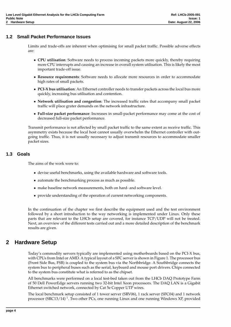
NAPI’s most important goals are to, in the event of an overload, reduce interrupts and early droppackets (i.e., early in the network stack). An overview of NAPI is given in Figure 2. It applies adaptiveinterrupt coalescing to offer a middle ground between an interrupt driven scheme and polling scheme.A NIC driver that supports NAPI only interrupts the system on the arrival of the first packet in abatch. Subsequently, it registers to the system that is has work and turns off interrupts concerningreceiving packets or running out of receive buffers (referred to as receive descriptors) in its DMAring. This clearly reduces the number of interrupts generated by the device. Furthermore, any packetsarriving after the DMA ring is filled will be dropped without disturbing the system. This approachmeets the second design goal.
Figure 2 The NAPI mechanism in Linux kernel 2.6.
Softirq plays a role in the NAPI as such that a softirq is activated to poll all devices that registeredto offer packets. They are allowed to set up to a configurable number of packets known as a quota.When this quota is exceeded and if it still has packets to offer (work_done < work_to_do), it is putback at the end of the polling queue. Otherwise, the device is removed from the queue and allowedto interrupt again.
The net effect of NAPI is that under low load, the system converges towards a interrupt driven scheme.Under heavy load, however, it will evolve to a polling scheme which effectively reduces the interrupt-to-packet ratio.
The situation so far is the following: supposing the system is flooded by incoming packets, NAPI’sadaptive interrupt coalescing prevents a flood of interrupts. If packets are coming faster than thesoftirq can process them, i.e. the device’s DMA ring is full, then the device silently drops the newpackets.
The kernel is thus able to process incoming packets as fast as it can. However, remember that softirqsare invoked upon return from an interrupt handler. With this infrastructure, the kernel will just try tokeep up with packet processing and user level code will never get any CPU time. Thus, the systemwill starve.
3.2.3 ksoftirqd
To get around this situation, Linux has implemented a low priority softirq daemon (ksoftirqd [4])which basically checks for any pending softirqs, if there is free CPU time. Recall that when a NIC hasraised an interrupt on packet reception, upon return from the interrupt handler, the softirq pollingfunction do_softirq() is invoked. This function will go through the list of pending softirq’s, eachtime calling their respective handlers. In the case of packet reception, NET_RX_SOFTIRQ is the sched-uled softirq and net_rx_action() it’s corresponding handler. If, for example, do_softirq() no-tices that after net_rx_action() returns there is another NET_RX_SOFTIRQ pending, then it doesnot call net_rx_action() again. Instead it wakes up one of the ksoftirqd processes (there is oneksoftirqd for each logical CPU 2) by calling wakeup_softirqd(), which will process any remainingpackets when it gets CPU time.
2see hyper-threading, page 5.
page 7
Low Level Gigabit Ethernet Analysis for the LHCb Computing F arm Ref: LHCb-2005-091Public Note Issue: 14 Description of the Tests Date: August 22, 2006
The ksoftirq mechanism ensures that user processes do not suffer under heavy traffic. On the otherhand, if the system acts as a network node, as is the case in the LHCb DAQ Project, then ksoftirqd willvirtually have all the CPU at its disposal.
3.3 Sending Packets
From a system performance point of view, sending of packets is much simpler. The NIC driver pro-vides a function through consistent DMA mapping which instructs the hardware to begin transmis-sion. Concurrent access to this function is prevented by use of a spinlock. Under heavy load, whenthe hardware is unable to keep up, packet transmission may be deferred to a low priority ksoftirqdthread.
Each device maintains a queue of packets to be transmitted, using a FIFO queue discipline by default.In case of any problems, such as the device being locked by another thread or CPU (the xmit_lockspinlock), or the transmit DMA ring being full, a softirq (NET_TX_SOFTIRQ) is scheduled and packettransmission will be postponed until a later point in time, regulated by the ksoftirqd.
4 Description of the Tests
Five different tests were carried out:
1. receiving of frames,
2. sending of frames,
3. response time measurement,
4. low-level analysis of PCI-X bus traffic,
5. kernel profiling.
All these tests are related to the different performance elements as set out under Section 1.1.
The first test was done with the SFC in combination with an IBM PowerNP NP4GS3 programmablenetwork processor [6]. It has 3 Gigabit Ethernet ports (Broadcom NetXtreme BCM5700 chipset) andan on-board FPGA (Xilinx Spartan) which allows configuring the board in various ways for sendingor receiving frames, e.g. endless, numbered... The NP4GS3 produces useful statistics (RxFrameRate,RxDataRate, FrameErrors,...) for analysing traffic.
For the sending of frames test, the SFC now operated as a source by running the Linux packet gen-erator PKTGEN [7]. It provides a loadable Linux module for high-performance benchmarking the TXprocess of both the device driver and NIC. Because PKTGEN is ”in-kernel”, it can generate very highpacket rates. This can be seen as the software counterpart of the network processor.
The third test measured response time while directly connecting the SFC and SRV and running a back-to-back pingpong test of 1,000 packets and plotting the minimum round-trip time (rtt) as a functionof the packet size. As the SuperMicro motherboard allows for bus speed selection through jumpersettings, measurements were done for different PCI-X bus speeds.
The aforementioned benchmarks measure the real performance of the network, but generally do notallow for identification of bottlenecks present. Therefore, lower level tests as PCI-X traffic analysis andkernel profiling were subsequently carried out, emphasising hardware and software, respectfully.
PCI-X traffic was analysed using the VMETRO PBT-615 PCI/PCI-X Bus Analyser. It extracts the bustraffic during a certain window of time. The accompanying BusView software allows for downloadingthe data from the board to a Windows PC. The measurements can be converted to raw ASCII files,ideal for automated bash scripting analysis.
The last test employed the OProfile package [8], a system-wide profiler for Linux systems, capableof profiling all running code at low overhead. It consists of a kernel driver and a daemon for collecting
page 8
Low Level Gigabit Ethernet Analysis for the LHCb Computing F arm Ref: LHCb-2005-091Public Note Issue: 14 Description of the Tests Date: August 22, 2006
sample data, and several post-profiling tools for turning data into information. OProfile leveragesthe hardware performance counters of the CPU to enable profiling of a wide variety of interestingstatistics, which can also be used for basic time-spent profiling. All code is profiled: hardware andsoftware interrupt handlers, kernel modules, the kernel, shared libraries, and applications.
Next, all tests and their accompanying results will be described in great detail.
page 9
Low Level Gigabit Ethernet Analysis for the LHCb Computing F arm Ref: LHCb-2005-091Public Note Issue: 16 Transmission Throughput and Delay Date: August 22, 2006
5 Receive Throughput and Delay
This test resulted in several ’throughput versus payload’ and ’throughput versus delay’ plots. Boththe dual and quad card were benchmarked by this test. Note that in the case of the quad card wewere limited to 3 ports due to the NP. For every plot, the theoretical Gigabit Ethernet limit is plotted.The calculation goes as follows. As mentioned in Section 3.1, the Ethernet header is 14 bytes. In thedatalink layer this is augmented with a 4 byte CRC-checksum. Thus, the total header is 18 bytes. Inthe physical layer, a preamble of 8 byte and an inter-frame gap of 12 byte is observed, resulting inan extra 20 byte overhead. All this can be written down in the following expression as function ofpayload p:
p + 14 + 4
p + 14 + 4 + 20.
Figure 3(a) shows the bit rate measured when sending to one port of the SFC from one port of theNP with a variable frame size. The bit rate measured at the output of the NP matches pretty well thetheory, apart from regular drops. According to the NP documentation, this behaviour is to be expectedwhen pushing this device to the Gigabit Ethernet limit. The SFC receive rate drops accordingly ofcourse. In the range of 0 through 200, this bit rate measured at the input of the SFC is much lower(data is lost). Then, it reaches the sent bit rate (no losses). Receiving on both ports of the dual card atthe same time, produces an identical plot.
Figure 3(b) also shows the theoretical limit of the PCI bus, calculated as
p + 14 + 4
p + 14 + 4 + 128/4
where the 128 bytes in the denominator represent the PCI minimum delay of 16 cycles of 64 bit be-tween bursts, and the division by 4 as conversion factor of 64 bit × 66 MHz = 533 MBps ≈ 4 GbpsPCI bandwidth with respect to 1 Gbps Ethernet. We see that, in the case of operating one single port,this PCI bandwidth will never pose any limit on Gigabit Ethernet transfers, even taking into accountthe fact that this is a theoretical value which will never actually be reached due to numerous non-idealities.
The same figure also shows a linear fit of the first part of the curve. The slope is 0.004, which is inagreement with measurements in [9]. In the continuation of this paper, we will however reach a dif-ferent conclusion with regard to what contributes to this slope.
The same measurements were done on an Intel quad port NIC, the resulting plot is shown in Fig-ure 4. The slope of the linear part now amounts to 0.002, a value insensitive to the inter-frame delaysetting of the NP. This slope is clearly worse than the 0.004 slope of the dual card. A more carefullook at the layout of the NIC board reveals that, whereas the dual port is basically one single IntelFW82546EB chip, the quad card has -naturally- two such chips, but also a lot of supporting chips suchas a SST 39VF020 2Mbit Flash memory bank, a Tundra Tsi310 PCI-X bridge and an Altera MAX 7000APLD. This may give cause to the quad card chipset being not as ’streamlined’ as the single-chip dualcard. During this test, no PCI-X transfer bottleneck was observed.
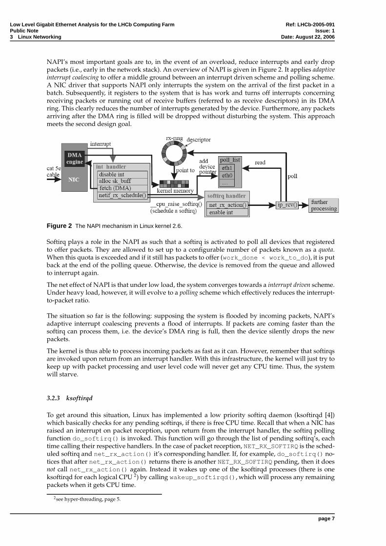
Later, the benchmarking process was automated using bash scripts. Each benchmark resulted in a’throughput versus payload’ plot, a ’throughput versus delay’ plot and a report file describing thecomplete test performed, the NIC, the driver and the settings used. An example plot is given in Fig-ure 5. For the receive throughput, the ’rcvd x’ curves are the important ones, with the ’send x’ plottedfor reference; and vice versa for the transmission throughput presented in the next section. All mea-surements agreed with the above conclusions.
6 Transmission Throughput and Delay
Using the knowledge of the previous benchmark automation, we were able to immediately implementa bash script to run the PKTGEN benchmarks. These also provided us with a transmission ’throughput
page 10
Low Level Gigabit Ethernet Analysis for the LHCb Computing F arm Ref: LHCb-2005-091Public Note Issue: 16 Transmission Throughput and Delay Date: August 22, 2006
0.2
0.3
0.4
0.5
0.6
0.7
0.8
0.9
1
0 200 400 600 800 1000 1200 1400 1600
bit r
ate
(Gb/
s)
payload (bytes)
Intel(r) 82546EB Dual port
received eth2send1->eth2
theory
(a) Plotted with theoretical Gigabit Ethernet limit.
0
0.5
1
1.5
2
2.5
3
3.5
4
0 200 400 600 800 1000 1200 1400 1600
bit r
ate
(Gb/
s)
payload (bytes)
Intel(r) 82546EB Dual port
receivedsend
theory.1/20*16/20*x+.085
pci bw
(b) Plotted with theoretical PCI bandwidth and slope.
Figure 3 Receive throughput from NP (port1) to SFC (eth2) for one port on a dual Intel NIC.
page 11
Low Level Gigabit Ethernet Analysis for the LHCb Computing F arm Ref: LHCb-2005-091Public Note Issue: 17 Response time Date: August 22, 2006
0.1
0.2
0.3
0.4
0.5
0.6
0.7
0.8
0.9
1
0 200 400 600 800 1000 1200 1400 1600
received eth2send 1->eth2received eth3send 2->eth3
theory
Figure 4 Receive throughput from NP to SFC for two ports simultaneously on a quad Intel NIC. ”sendx→ethy”identifies source (x) and destination (y) port.
versus payload’ and ’throughput versus delay’ plots, each for different delays and payloads, respect-fully.
For the dual cards, no significant decrease in performance was observed. Sending on one or two portsgave basically the same plot, as can be seen in Figure 6.
For the quad cards, some more interesting results are obtained, see Figure 7. Going from from 1 to2 ports sending, the behaviour is basically the same. Starting from 3 transmitting ports onwards, achange in performance is observed. Small delays of 3 µs and 5 µs come together and, for higher de-lays, we see that the throughput actually increases.
There is an important remark to make concerning the tests conducted under Section 5 and 6. Dueto the extensive time it takes to perform a full length sweep, the points of measurement were greatlyreduced to do so-called quick runs. This means that the importance of one point of a plot increases,while its accuracy of course does not. This goes for both the receive and transmission test. In addition,the former test has to deal with the NP being pushed to its limits, and the latter suffers from variableoperating system conditions.
7 Response time
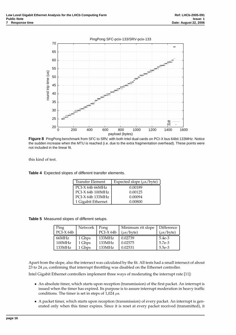
The aim of this test is to retrieve the slope of the delay as function of payload. The minimum roundtrip time (rtt) was measured using a scripted ’ping -A’ command, for gradually increased payloadsize, each time taking 1,000 measurements. Note that the effective payload is 46 bytes larger now sincethe final packets also contain an ICMP header (8 bytes), an IP header (20 bytes), an Ethernet header(14 bytes) and CRC-checksum (4 bytes). The resulting data points were plotted and linearly fitted withgnuplot, giving the slope and intersect.
Following [10], this slope compared to an expected value gives an insight in the total amount of timespent in other parts of the system. An overview of the expected slopes is given in Table 4.
The measured values are presented in Table 5, along with their difference compared to the total ex-pected rtt going from SFC04 to SRV06 and back, effectively going through every component twice.All the values are well in agreement with the expected ones, given the rather large margin of error for
page 12
Low Level Gigabit Ethernet Analysis for the LHCb Computing F arm Ref: LHCb-2005-091Public Note Issue: 17 Response time Date: August 22, 2006
0.1
0.2
0.3
0.4
0.5
0.6
0.7
0.8
0.9
1
0 200 400 600 800 1000 1200 1400 1600
bit r
ate
(Gb/
s)
payload (bytes)
NP->SFC - Intel dual card, two ports to NP - 2.6.11-smp
send 3rcvd 3
send 13rcvd 13
send 23rcvd 23
send 33rcvd 33theory
(a) Throughput as function of payload for different delays.
0
0.1
0.2
0.3
0.4
0.5
0.6
0.7
0.8
0.9
1
1.1
0 5 10 15 20 25 30 35 40
bit r
ate
(Gb/
s)
delay (us)
NP->SFC - Intel dual card, two ports to NP - 2.6.11-smp
send 50rcvd 50
send 550rcvd 550
send 1050rcvd 1050
(b) Throughput as function of delay for different payloads.
Figure 5 Receive throughput from NP to SFC for two ports simultaneously on a dual Intel NIC. (scriptedbenchmark)
page 13
Low Level Gigabit Ethernet Analysis for the LHCb Computing F arm Ref: LHCb-2005-091Public Note Issue: 17 Response time Date: August 22, 2006
0
0.1
0.2
0.3
0.4
0.5
0.6
0.7
0.8
0.9
1
0 5 10 15 20 25 30 35 40
bit r
ate
(Gb/
s)
delay (us)
SFC->NP - Intel dual card, one port pktgen - 2.6.11-smp
Figure 6 Transmission throughput as function of delay for different payloads from SFC for a dual port Intel NIC.
page 14
Low Level Gigabit Ethernet Analysis for the LHCb Computing F arm Ref: LHCb-2005-091Public Note Issue: 17 Response time Date: August 22, 2006
0
0.1
0.2
0.3
0.4
0.5
0.6
0.7
0.8
0.9
1
0 200 400 600 800 1000 1200 1400 1600
bit r
ate
(Gb/
s)
payload (bytes)
SFC->NP - Intel quad card, one port pktgen - 2.6.11-smp
send 3send 5send 9
send 20send 30send 40
theory
(a) One port sending.
0
0.1
0.2
0.3
0.4
0.5
0.6
0.7
0.8
0.9
1
0 200 400 600 800 1000 1200 1400 1600
bit r
ate
(Gb/
s)
payload (bytes)
SFC->NP - Intel quad card, two port pktgen - 2.6.11-smp
send 3send 5send 9
send 20send 30send 40
theory
(b) Two ports sending.
0
0.1
0.2
0.3
0.4
0.5
0.6
0.7
0.8
0.9
1
0 200 400 600 800 1000 1200 1400 1600
bit r
ate
(Gb/
s)
payload (bytes)
SFC->NP - Intel quad card, three port pktgen - 2.6.11-smp
send 3send 5send 9
send 20send 30send 40
theory
(c) Three ports sending.
0
0.1
0.2
0.3
0.4
0.5
0.6
0.7
0.8
0.9
1
0 200 400 600 800 1000 1200 1400 1600
bit r
ate
(Gb/
s)
payload (bytes)
SFC->NP - Intel quad card, four port pktgen - 2.6.11-smp
send 3send 5send 9
send 20send 30send 40
theory
(d) Four ports sending.
Figure 7 Transmission throughput as function of delay for different payloads from SFC to NP for a quad portIntel NIC.
page 15
Low Level Gigabit Ethernet Analysis for the LHCb Computing F arm Ref: LHCb-2005-091Public Note Issue: 17 Response time Date: August 22, 2006
20
25
30
35
40
45
50
55
60
65
70
0 200 400 600 800 1000 1200 1400 1600
roun
d tr
ip ti
me
(us)
payload (bytes)
PingPong SFC-pcix-133/SRV-pcix-133
fitrrt
Figure 8 PingPong benchmark from SFC to SRV, with both Intel dual cards on PCI-X bus 64bit 133MHz. Noticethe sudden increase when the MTU is reached (i.e. due to the extra fragmentation overhead). These points werenot included in the linear fit.
this kind of test.
Table 4 Expected slopes of different transfer elements.
Apart from the slope, also the intersect was calculated by the fit. All tests had a small intersect of about23 to 24 µs, confirming that interrupt throttling was disabled on the Ethernet controller.
Intel Gigabit Ethernet controllers implement three ways of moderating the interrupt rate [11]:
• An absolute timer, which starts upon reception (transmission) of the first packet. An interrupt isissued when the timer has expired. Its purpose is to assure interrupt moderation in heavy trafficconditions. The timer is set in steps of 1,024 µs.
• A packet timer, which starts upon reception (transmission) of every packet. An interrupt is gen-erated only when this timer expires. Since it is reset at every packet received (transmitted), it
page 16
Low Level Gigabit Ethernet Analysis for the LHCb Computing F arm Ref: LHCb-2005-091Public Note Issue: 18 PCI-X Analysis Date: August 22, 2006
is not guaranteed to generate an interrupt if the network traffic is high. Its purpose is rather tolower the latency in low traffic situations. The timer is set in steps of 1,024 µs.
• An interrupt throttle mechanism can be used to set an upper boundary on the interrupt rategenerated by the controller. The corresponding parameter is the maximum interrupt rate.
While the first two timers work independently for reception and transmission of frames, the throttlemechanism can be used to ensure that despite quickly varying traffic conditions in both directions,the total interrupt rate does not increase above the given value
It is clear that one can view NAPI as a software implementation of interrupt throttling, but actuallyNAPI goes much further than just that, since it is much more dynamic and also implements a completepolling mechanism (see page 6).
In the case of a DAQ system, it is obviously preferred that the system limits itself to what it can do(with NAPI), possibly being in a very busy loop of ”packet processing”, in order to not lose packets.Note that thanks to the softirq mechanism, the system will still not starve. With interrupt throttling,the Ethernet controller will discard packets before the PC is at its limit, which is clearly not optimal.
In fact, the whole point of hardware interrupt throttling is actually to assist operating systems whichdo facilitate any NAPI-support (e.g. Linux kernel 2.4 and earlier).
8 PCI-X Analysis
Similar to network overhead issues, PCI/PCI-X bus protocols also impose penalties on small packettraffic. In addition to the actual data transfer, each bus transaction requires extra control cycles whichintroduce overhead (e.g., arbitration latency, address phases, attribute phases, wait states). This over-head reduces the efficiency of each transaction as well as overall bus performance. For example, plac-ing a 64-byte data packet over PCI-X Bus, requires 8 bus cycles while the overhead of a transactionrequires a minimum of 4 cycles (3 to initiate and 1 cycle to terminate). A ”worst case” will add up to16 wait cycles. Bus overhead costs become more pronounced with small packet traffic as bus controland wait cycles consume a larger fraction of each bus transaction.
All PCI/PCI-X measurements shown in this section are taken on the SRV06 server, since it allowedfor a flexible PCI/PCI-X bus type and speed setting. Also, it was not possible to perform PCI-X mea-surements in the SFC, because it has only one PCI-X slot, and the VMETRO PBT-615 does not featurea Device-Under-Test slot on top of the card.
8.0.1 A Typical Trace
Figure 9 Transition between smooth and stumble PCI traffic. (1 of 2 ports receiving @ PCI 64bit 66MHz)
page 17
Low Level Gigabit Ethernet Analysis for the LHCb Computing F arm Ref: LHCb-2005-091Public Note Issue: 18 PCI-X Analysis Date: August 22, 2006
Figure 9 shows the two regimes of transmission across the PCI bus in one single trace. The dark areasmean that the signal varies a lot, indicating frames are transmitted across the bus. Notwithstandingthat this plot was taken in PCI mode, exactly the same behaviour was observed when analysing thePCI-X traffic. This section summarises the flow of traffic on the bus, going from the smooth to thestumble regime.
During the smooth regime, all frames are nicely put on the PCI bus behind each other (inter-framedelay of 54 CLKs or 0.8 µs). The Intel Pro/1000 MT Ethernet Controller uses receive and transmitdescriptors to keep the books. Such a descriptor is basically a pointer to memory space, indicating ablock of configurable size for the NIC to store a received frame or read in a frame to send. From hereon, we will concentrate on reception of frames. When a frame is received, the Ethernet controller usesa receive descriptor (RD) to find out where to store the frame. After the DMA transfer finishes, thisreceive descriptor is sent back to the driver to advertise the presence of a frame at that location (delayof 7 CLKs). Under normal circumstances, the driver will provide the NIC with newly allocated RDsin time before the card runs out of descriptors. This is what happens in the smooth regime, where thedriver sends a new bunch of RDs every 3800 CLKs (58 µs). A RD bunch transfer continues until allallocated descriptors for that batch have been provided, or, the card’s frame receive buffer is nearlyfull and the card terminates the descriptor transfer by raising the STOP# signal in order not to lose anyframes. Since a NP is flooding the card during this test (with approx. 1 million packets per second),the latter will always happen, as we see on the STOP# signal line. After the descriptor transfer, theframe receive buffer is quickly emptied to regain the time lost during this transfer. All frames are nowput on the PCI bus with a minimum delay of 7 CLKs in between.
Clearly, under persistent heavy traffic load, the card will become unable to fetch enough descriptorsto keep up with the high frame rate, and at the same time sent every single frame to the system. Thecard will have to allow for a FIFO receive buffer overrun and silently drop frames until it has somemore RDs to quickly empty the buffer and try start receiving again. The relief is of short duration,however, as the card will soon have exhausted it (already) very limited pool of RDs, and it will haveto wait again.
This is what happens in the second so-called stumble regime, where huge gaps of 4000 CLKs showthe lack of RDs is preventing any further traffic. This results in many FIFO buffer overruns and a hugepacket loss of up to 500k packets per second. Furthermore, the omnipresent STOP# indicates that anytransfer that takes longer that absolutely necessary is abruptly terminated by the NIC.
In the smooth part, the system can process 1 frame per microsecond (i.e. what the NP sends). Whentumbling into stumble regime, this number degrades to a value of merely 0.3 frames per microsecondor 0.28 Gb/s, cf. earlier results, e.g. Figure 3. This also confirms that the linear part for small packetsizes is caused by this stumble behaviour.
Where one might be tempted to think the PCI bus or NIC is the cause for this bottleneck, calculationson PCI bus utilisation proved otherwise. During the whole trace, peak data rates did not reach anyhigher than 250 MB/s, which is still far away from the PCI limit (i.e. 533 MB/s in this case). Thiswas already a clear indication that nor the PCI bus, nor the card were responsible for this stumblebehaviour. Note that this trace was taken for a single port receiving frames. It is clear that a PCI 64bit66MHz will pose a bottleneck when more than 1 port is operating on the same bus.
8.0.2 PCI-X Traces
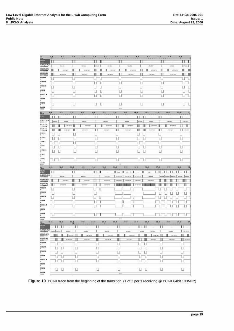
Figure 10 visualises the PCI-X trace from the start of the transmission by the NP to SRV06. A closeranalysis of the bus traffic revealed the following pattern in the smooth receive regime:
1. Four frames are transferred to main memory through DMA bursts with an inter-frame delay ofabout 45 CLKs or 0.4 µs.
2. Right afterwards (i.e. 25 CLKs or 0.2 µs), 4 corresponding receive descriptors are written back tothe driver.
3. Step 1 and 2 are repeated 16 times (containing a total of 64 frames), after which four new ReceiveDescriptor Tail (RDT) are received from the driver, each allowing the Ethernet controller to fetch16 new consecutive descriptors.
page 18
Low Level Gigabit Ethernet Analysis for the LHCb Computing F arm Ref: LHCb-2005-091Public Note Issue: 18 PCI-X Analysis Date: August 22, 2006
Figure 10 PCI-X trace from the beginning of the transition. (1 of 2 ports receiving @ PCI-X 64bit 100MHz)
page 19
Low Level Gigabit Ethernet Analysis for the LHCb Computing F arm Ref: LHCb-2005-091Public Note Issue: 19 Kernel Profiling Date: August 22, 2006
Compared to PCI, it was observed that PCI-X traffic contained less errors and less accompanyingWAIT states. Along with higher clock frequencies, the more intelligent use of WAIT states and so-called split transactions instead of delayed transactions are among the most important features of thePCI-X protocol.
Analysing plots as shown in Figure 9 and 10 is tedious and time consuming. Luckily, the BusViewsoftware allowed for data to be converted into plain ASCII files which in turn can be manipulatedusing numerous Linux tools such as grep and awk to extract the desired information. Using Postscriptlanguage, the extracted data was then converted into custom made plots, e.g. Figure 11.
0 clk
0 us
5000 clk
75 us
10000 clk
150 us
15000 clk
225 us
20000 clk
300 us
25000 clk
375 us
30000 clk
450 us
35000 clk
525 us
40000 clk
600 us
45000 clk
675 us
50000 clk
750 us
wdwd
3
wdwdwdwd
7
wdwdwdwd
11
wdwdwdwd
15
wdwdwdwd
19
wdwdwdwd
23
wdwdwdwd
27
wdwdwdwd
31
wdwdwdwd
35
wdwdwdwd
39
wdwdwdwd
43
wdwdwdwd
47
wdwdwdwd
51
wdwdwdwd
55
wdwdwdwd
59
wdwdwdwd
63
wdwdwdwd
67
wdwdwdwd
71
wdwdwdwd
75
wdwdwdwd
79
wdwdwdwd
83
wdwdwdwd
87
wdwdwdwd
91
wdwdwdwd
95
wdwdwdwd
99
wdwdwdwd
103
wd
104
wdwdwd
107
wdwdwdwd
111
wdwdwdwd
115
wdwdwdwd
119
wdwdwdwd
123
wdwdwdwd
127
wdwdwdwd
131
wdwdwdwd
135
wdwdwdwd
139
wdwdwdwd
143
wdwdwdwd
147
wdwdwdwd
151
wdwdwdwd
155
wdwdwdwd
159
wdwdwdwd
163
wdwdwdwd
167
wdwdwdwd
171
wdwdwdwd
175
wdwdwdwd
179
wdwdwdwd
183
wdwdwdwd
187
wdwdwdwd
191
wdwdwdwd
195
wdwdwdwd
199
wdwdwdwd
203
wdwdwdwd
207
wd
208
wdwdwd
211
ihi-
214
wdwdwdwd
215
wdwdwdwd
rdt
219
wdwdwdwd
223
rdt
226
wdwdwdwd
227
rdtwdwdwdwd
231
rdti+wd wdwdwdwd
235
wdwdwdwd
239
wdwdwdwd
243
wdwdwdwd
247
wdwdwdwd
251
wdwdwdwd
255
wdwdwdwd
259
wdwdwdwd
263
wdwdwdwd
267
wdwdwdwd
271
wdwdwdwd
275
wdwdwdwd
279
wdwdwdwd
ihi-
rdt
283
wdwdwdwd
287
rdt
290
wdwdwdwd
291
wdwdwdwdrdt
295
rdti+
wd wdwdwdwd
299
wdwdwdwd
303
wdwdwdwd
307
wdwdwdwd
311
wdwdwdwd
315
wdwdwdwd
319
wdwdwdwd
323
wdwdwdwd
327
wdwdwdwd
331
wdwdwdwd
335
wdwdwdwd
339
wdwdwdwd
343
wdwdwdwd
ihi-
rdt
347
wdwdwdwd
351
rdt
354
wdwdwdwd
355
rdtwdwdwdwd
359
rdti+
wd wdwdwdwd
363
wdwdwdwd
367
wdwdwdwd
371
wdwdwdwd
375
wdwdwdwd
379
wdwdwdwd
383
wdwdwdwd
387
wdwdwdwd
391
wdwdwdwd
395
wdwdwdwd
399
wdwdwdwd
403
wdwdwdwd
407
wdwdwdwd
ihi-
rdt
411
wdwdwdwd
415
rdt
418
wdwdwdwd
419
rdtwdwdwdwd
423
rdti+
wd wdwdwdwd
427
wdwdwdwd
431
wdwdwdwd
435
wdwdwdwd
439
wdwdwdwd
443
wdwdwdwd
447
wdwdwdwd
451
wdwdwdwd
455
wdwdwdwd
459
wdwdwdwd
463
Figure 11 Interpreted Postscript plot of the PCI trace from Figure 9 (1 of 2 ports receiving @ PCI 64bit 66MHz)showing left to right and top to bottom the advancing time axis. wd indicates a descriptor is written to the driver,signalling the presence of a received frame in main memory. The reception of Receive Descriptor Tails (rdt) fromthe driver in blocks of 4 is very clear. The small gaps in the smooth regime signal that the NIC has employed anew RDT and is consecutively reading in the 16 RDs this RDT points to.
While analysing these custom made plots, some arguments implying a software bottleneck were gath-ered. A look at the kernel’s memory management information, provided by the /var/slabinfo file,made clear that memory access was responsible for the large gaps in stumble regime. The gaps canbe explained by the DMA slab freeings. Normally, a CPU keeps a freed DMA slab in its bucket (onebucket per CPU). Occasionally, however, a large bunch of main memory is reallocated by the driverand then the main memory needs to be accessed, preventing others, e.g. DMA accesses by the NIC,from accessing the main memory. Beware, not the memory bank technology but the way the driverseems to handle memory access is causing the bottleneck. Simple on the back-of-the-envelope calcu-lations show that the DDR-2 400MHz (PC2-3200) provides enough raw bandwidth.
It is clear that the Intel Pro/1000 MT Ethernet Controller card, when used in combination with a fastPCI-X host bus, will not become a bottleneck, even for quad port operation. Therefore, the next sectionwill look closer to the software side of the network infrastructure, i.e. the Linux operating system andthe e1000 Ethernet controller driver.
9 Kernel Profiling
It is instructive to understand where the system is spending most of its time. The OProfile reportfile outputs the number of times a certain function (in user space, kernel, driver,...) has been called andwhat percentage of the total samples taken this represents. This benchmark was run under a unipro-cessor compiled version of kernel 2.6.12 with hyper-threading disabled. This proved to be beneficial
page 20
Low Level Gigabit Ethernet Analysis for the LHCb Computing F arm Ref: LHCb-2005-091Public Note Issue: 19 Kernel Profiling Date: August 22, 2006
for our purposes as all calls are then made on one single CPU, allowing for a true sequential analy-sis of function calls. Furthermore, as a positive side effect, this simplified the report file to only onesingle data set. One drawback when running the uniprocessor kernel, was the system becoming re-ally starved when flooded with packets by the NP. This, unfortunately, renders the gathered statisticsless representative, since under 100% CPU usage the schedueling has a non-negledgible influence. Tosomewhat diminish this indeterminism, the IRQ affinity was manually set and the irqbalance daemondisabled.
Figure 12 Summary of relative occupation of the CPU during a 5 minute flood by the NP (1 of 2 ports @ PCI-X64bit 133MHz) for a different weight values. 64 is the hard coded value of the unmodified e1000 driver.
While performing this benchmark, a first attempt was made to tune the e1000 NIC driver by increas-ing the netdev->weight value in main_e1000.c (see [12]) from its original hard coded value of64. One Receive Descriptor Tail (RDT) is a pointer indicating the presence of 16 consecutive ReceiveDescriptors in main memory. By default, 4 such RDTs will be sent in one NAPI poll (see Figure 11),since 16 × 4 = 64. Thus, increasing this value will increase the number of RDTs transmitted in oneperiod, e.g. 12 in Figure 13 for a weight of 196. Any remaining RDTs less than the budget (i.e. quotaallowed by NAPI polling function) are sent afterwards when the scheduled low priority ksoftirq dae-mon is called. At first sight this does increase the number of RDTs sent to the NIC at once, and as suchshould reduce the packet loss rate. However, this is not the case. On the contrary, on the short-termmore RDTs are sent in one NAPI poll, but there is now a larger gap between every NAPI poll, effec-tively reducing the number of RDTs in the long run: in 98,500 CLKs (1 ms @ 100 MHz) from 28 RDTsfor the default weight value of 64, to 25 RDTs for the same period of time, for a weight of 196. This isa decrease of 11%, which is clearly not desirable. Also, the transition from smooth to stumble regimewill happen sooner. This is supported by the observed increase in packetloss from 43% to 54%.
Results of the OProfile test are summarised in Figure 12. It shows that by increasing the weight, lesstime is spent in cleaning descriptors by the driver (e1000_clean_rx_irq()) and socket buffers bythe kernel (skb_release_data()). On the other hand, more time is spent allocating (new) RDs(e1000_alloc_rx_buffers()). This is as expected when increasing the short-term amount ofRDTs provided. The decrease of eth_type_trans() calls again provides some indication that thereare less packets to process, i.e. packets have been lost.
Given the above results of trying to tune the weight value, we will now concentrate on the profile ofthe original hard coded weight of 64. Analysing the exact content of the most frequently made callsin the original case, it is established that all are involve with freeing and reallocating RDs. This gavecause for the idea to tune the e1000 driver to more cleverly handle this RD processing, and implementsome kind of Receive Descriptor recycling. This idea, along with its implementation in the e1000 sourcecode, will be covered in the next section.
page 21
LowLevelG
igabitEthernetA
nalysisfor
theLH
Cb
Com
putingF
armR
ef:LH
Cb-2005-091
Public
Note
Issue:1
9K
ernelProfiling
Date:
August22,2006
0 clk
0 us5000 clk
50 us10000 clk
100 us15000 clk
150 us20000 clk
200 us25000 clk
250 us30000 clk
300 us35000 clk
350 us40000 clk
400 us45000 clk
450 us50000 clk
500 us55000 clk
550 us60000 clk
600 us65000 clk
650 us70000 clk
700 us75000 clk
750 us80000 clk
800 us85000 clk
850 us90000 clk
900 us95000 clk
950 us100000 clk
1000 us105000 clk
1050 us110000 clk
1100 us115000 clk
1150 us120000 clk
1200 us125000 clk
1250 us130000 clk
1300 us
ih
213
i-
215
rdt
841
rdt
849
rdt
855
rdt
873
rdt
883
rdt
893
rdt
903rdt
915
rdt
927
rdt
941
rdt
965
rdt
1005
rdt
1045
rdt
1327
rdt
1335
rdt
1343
rdt
1353
rdt
1361
rdt
1371
rdt
1953
rdt
1961
rdt
1971
rdt
1981
rdt
1991
rdt
2003rdt
2013
rdt
2025
rdt
2037
rdt
2051
rdt
2075rdt
2115
rdt
2423
rdt
2435
rdt
2443
rdt
2451
rdt
2461
rdt
2469
rdt
2479
Figure
13Interpreted
Postscriptplotofa
PC
I-X64bit100M
Hz
trace(1
of2ports
receiving).The
write-back
ofdescriptors
hasbeen
hiddenfor
readability.
page22
Low Level Gigabit Ethernet Analysis for the LHCb Computing F arm Ref: LHCb-2005-091Public Note Issue: 110 Tuning of the e1000 NIC Driver Date: August 22, 2006
10 Tuning of the e1000 NIC Driver
The e1000 driver source code can be found in your kernel source directory or [12], of which thee1000_main.c file contains most of the driver’s basic functionality. For example, e1000_intr() isthe interrupt handler which is invoked when an interrupt is raised by the Ethernet controller. In thisfunction, the Interrupt Cause Register (ICR) is read, and if the NIC indicated it has received packetsand wrote them to memory, all interrupt involving packet reception are disabled and the device sched-ules itself in the NAPI queue. At some later point, a softirq is activated and will poll all devices thatregistered to offer packets. The adapter->netdev->pollmember points to the e1000 NAPI pollingfunction, e1000_clean(). It determines the amount of work_to_do, based on the minimum of ei-ther the allowed quota received from NAPI or the configurable adapter->netdev->weight value(now left unchanged at the original hard coded value of 64). Now, e1000_clean() basically callse1000_clean_rx_irq() to send received data up the network stack. e1000_clean_rx_irq()finishes by calling e1000_alloc_rx_buffers() to reallocate used receive descriptors. It is in thisfunction that we find the include/linux/skbuff.h::dev_alloc_skb() function call.
This short overview points out that the most frequently called functions of Section 9 (Figure 12, weight64) are all related to one single very time consuming operation: the freeing of large heaps of memory.Especially when talking small payload sizes, it is clear that the situation only worsens due to moredescriptors and thus more kfree() overhead.
It is this overhead that prevents the driver from quickly sending new RDs to the Ethernet controller, asthey need to be freed and reallocated first. This is why we implemented a Receive Descriptor Recyclingmechanism. The idea is to allocated a fixed number of permanent descriptors which are reused everytime around, effectively taking away the need for the costly kfree() overhead. The only processingthat remains to be done is resetting some fields in the descriptors. The remainder of this section willoutline the details of this implementation.
10.1 Receive Descriptor Recycling
First we needed to store the permanent buffers in the e1000_adapter struct (see e1000.h), so theybecome associated with each Ethernet controller present in the system. For this, it was extended bytwo members: an array to store the preallocated socket buffers, and an array to point to the associateddata fields. We opted for a fixed array size of 2,048 which was the RxDescriptors e1000 driverparameter used in all previous tests.
During the driver initialisation, we loop through these arrays to allocated memory and setup the datapointers. To prevent the driver from freeing our allocated array, we artificially increase the numberof users for each socket buffer to 2 by calling skb_get(). As long as the number of users remainshigher than 2, kfree_skb() will never free them, since it believes someone is still using the socketbuffer and its data.
This is realised by altering the driver function call flow in e1000_alloc_rx_buffers(). Here thecall to dev_alloc_skb(), which would return a fresh allocated socket buffer (skb), is replaced byreturning one of our preallocated skbs in the array. Next, the skb reset is implemented by the newlyadded reset_skb() function.
Please refer to Appendix A for a detailed overview of exact code implementations.
10.2 Results
To check for any performance increase for small packet sizes, the ’Receive Throughput and Delay’test (see Section 5) was repeated. For small frame sizes, the RDR-enabled driver was able to reducepacket loss by 40%, see Figure 14 and 15. The influence is the most clear for short delay packets. Theperformance of higher payloads remained unchanged with RDR.
page 23
Low Level Gigabit Ethernet Analysis for the LHCb Computing F arm Ref: LHCb-2005-091Public Note Issue: 110 Tuning of the e1000 NIC Driver Date: August 22, 2006
0.1
0.2
0.3
0.4
0.5
0.6
0.7
0.8
0.9
1
0 200 400 600 800 1000 1200 1400 1600
bit r
ate
(Gb/
s)
payload (bytes)
NP->SRV06 - Intel dual card, two ports to NP (HACKED, OK affinity) - 2.6.12
rcvd 3rcvd 5rcvd 9
rcvd 20rcvd 30rcvd 40theory
(a) Throughput as function of payload for different delays, using the RDR-enabled driver.
0.1
0.2
0.3
0.4
0.5
0.6
0.7
0.8
0.9
1
0 200 400 600 800 1000 1200 1400 1600
bit r
ate
(Gb/
s)
payload (bytes)
NP->SRV06 - Intel dual card, two ports to NP (OFFICIAL, OK affinity) - 2.6.12
rcvd 3rcvd 5rcvd 9
rcvd 20rcvd 30rcvd 40theory
(b) Throughput as function of payload for different delays, using the official e1000 driver v6.0.54-k2-NAPI.
Figure 14 Receive throughput from NP to SRV for two ports on a dual Intel NIC.
page 24
Low Level Gigabit Ethernet Analysis for the LHCb Computing F arm Ref: LHCb-2005-091Public Note Issue: 110 Tuning of the e1000 NIC Driver Date: August 22, 2006
0.1
0.2
0.3
0.4
0.5
0.6
0.7
0.8
0.9
1
0 200 400 600 800 1000 1200 1400 1600
bit r
ate
(Gb/
s)
payload (bytes)
NP->SRV06 - Intel dual card, one port to NP (HACKED, OK affinity) - 2.6.12
rcvd 3rcvd 5rcvd 9
rcvd 20rcvd 30rcvd 40theory
(a) Throughput as function of payload for different delays, using the RDR-enabled driver.
0.1
0.2
0.3
0.4
0.5
0.6
0.7
0.8
0.9
1
0 200 400 600 800 1000 1200 1400 1600
bit r
ate
(Gb/
s)
payload (bytes)
NP->SRV06 - Intel dual card, one port to NP (OFFICIAL, OK affinity) - 2.6.12
rcvd 3rcvd 5rcvd 9
rcvd 20rcvd 30rcvd 40theory
(b) Throughput as function of payload for different delays, using the official e1000 driver v6.0.54-k2-NAPI.
Figure 15 Receive throughput from NP to SRV for one port on a dual Intel NIC.
page 25
Low Level Gigabit Ethernet Analysis for the LHCb Computing F arm Ref: LHCb-2005-091Public Note Issue: 111 Conclusion Date: August 22, 2006
0.1
0.2
0.3
0.4
0.5
0.6
0.7
0.8
0.9
1
0 200 400 600 800 1000 1200 1400 1600
bit r
ate
(Gb/
s)
payload (bytes)
NP->SRV06 - Intel dual card, two ports to NP - kernel 2.6.12
originalwith RDR
theory
Figure 16 Comparative plot of RDR improvement.
11 Conclusion
Several benchmarks were performed on Gigabit Ethernet hardware and the Ethernet controller driver.Among the aspects analysed in this work were throughput, packet loss, response time and efficientresource utilisation. Emphasis was put on small packet size network traffic, to be used for calibra-tion of the LHCb experiment. It was shown that the current bottleneck lies in the way the e1000driver handles the receive descriptor memory management, which proofs to be fatal for small packetsizes. In order to remedy the situation, a Receive Descriptor Recycling mechanism was proposed andimplemented in the official e1000 driver. Results have shown an improvement of small packet sizeperformance by 40% in terms of increase in throughput and reduction of packet loss.
page 26
Low Level Gigabit Ethernet Analysis for the LHCb Computing F arm Ref: LHCb-2005-091Public Note Issue: 1A Receive Descriptor Recycling Patch Date: August 22, 2006
12 References
[1] Reliability of datagram transmission on Gigabit Ethernet at full link load, A. Barczyk, A. Carbone et al,LHCb Tech Note, LHCb-2004-030, April 2004.
[2] Hyper-threading Technology on the Intel Xeon Processor Family for Servers, Intel white paper.
[3] IEEE 802 Standard on Ethernet Frame Format.
[4] Understanding the Linux Kernel, 2nd Edition, D. Bovet, O’Reilly, 2003
[5] Beyond Softnet, J. Salim, R. Olsson et al., Proc. 5th Ann. Linux Showcase and Conf., Oakland,California, November 2001.
[6] IBM PowerNP network processor: Hardware, software, and applications, J. R. Allen, Jr. et al, IBM J. Res.& Dev., vol. 47, no. 2/3, March/May 2003.
[7] PKTGEN, The Linux Packet Generator, R. Olsson, Linux-Kongress, Erlagen, 2004
[8] OProfile, http://oprofile.sourceforge.net
[9] High Rate Packets Transmission on Ethernet LAN Using Commodity Hardware, A. Barczyk, B. Gaidiozet al., IEEE Trans. Nucl. Sci., accepted for publication.
[10] Performance of 1 and 10 Gigabit Ethernet Cards with Server Quality Motherboards, R. Hughes-Jones etal.
[12] The Linux Cross Reference project, http://lxr.linux.no
A Receive Descriptor Recycling Patch
Remark: This patch is written for kernel 2.6.12 and e1000 version 6.0.54-k2-NAPI. This patch is pro-vided ”as-is”, without express or implied warranty of any kind. For more details, see the GNU GeneralPublic License. Furthermore, note that the patched driver has not been tested to the greatest of extend.
+ /*+ We keep skb->users > 1, so that kfree() will never actually free anything.+ (note for later: kfree() will decrement users by one, so we should increase every time.)
page 27
Low Level Gigabit Ethernet Analysis for the LHCb Computing F arm Ref: LHCb-2005-091Public Note Issue: 1A Receive Descriptor Recycling Patch Date: August 22, 2006
+ */+ {+ int i;+ unsigned int bufsz = adapter->rx_buffer_len + NET_IP_ALIGN;+ struct sk_buff* skb;++ for (i=0;i<2048;i++) {+ // prealloc a set of buffers which are ready for use+ skb = dev_alloc_skb(bufsz);+ adapter->prealloc_buff[i] = skb;+ // increase users by one, so it becomes 2. (see skb_alloc() for init value)+ skb = skb_get(skb);+ // store copy of data+ adapter->data[i] = skb->data;+ }+ }
Low Level Gigabit Ethernet Analysis for the LHCb Computing F arm Ref: LHCb-2005-091Public Note Issue: 1A Receive Descriptor Recycling Patch Date: August 22, 2006
+ unsigned int bufsz = adapter->rx_buffer_len + NET_IP_ALIGN;+ struct sk_buff* skb;++ for (i=0;i<2048;i++) {+ skb = adapter->prealloc_buff[i];+ // decrease users to 1+ dev_kfree_skb(skb);+ // now we will free+ dev_kfree_skb(skb);+ }+ }
}
*** 3093,3099 ****--- 3126,3171 ----+ static void+ reset_skb(struct sk_buff *skb, struct e1000_adapter *adapter, unsigned int i)+ {+ u8 *data = adapter->data[i];+ unsigned int size = adapter->rx_buffer_len + NET_IP_ALIGN;++ /* Get the DATA. Size must match skb_add_mtu(). */+ size = SKB_DATA_ALIGN(size);++ //if (!data)+ // goto nodata;
Low Level Gigabit Ethernet Analysis for the LHCb Computing F arm Ref: LHCb-2005-091Public Note Issue: 1A Receive Descriptor Recycling Patch Date: August 22, 2006