Page 1
Low Pressure Filter/Suction FilterPi 220
Nominal pressure 10 bar (140 psi), up to nominal size 160
1. Features
-
-
High performance filters for modern hydraulic systems
-
Provided for pipe installation
Modular system
Compact design
Minimal pressure drop through optimal flow design
Visual/electronic/electronical maintenance indicator
Threaded connections
-
.
-
-
Quality filters, easy to service
Equipped with highly efficient Mic or Sm-x filter elements
Beta rated elements according to ISO 16889
Elements with high differential pressure stability and dirt holding
capacity
Worldwide distribution
Page 2
Low Pressure Filter/Suction Filter Pi 220 up to NG 160 2
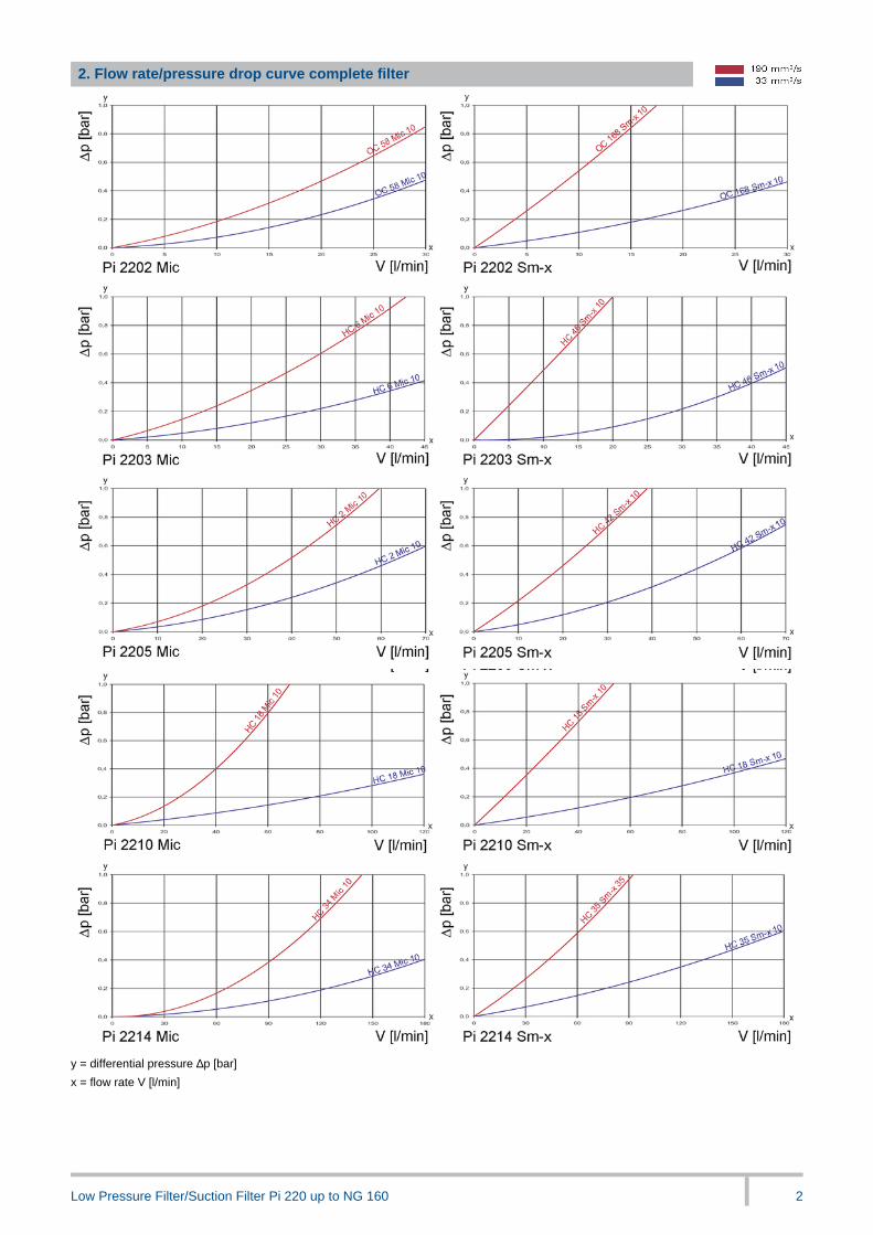
2. Flow rate/pressure drop curve complete filter
y = differential pressure ∆p [bar]
x = flow rate V [l/min]
Page 3
Low Pressure Filter/Suction Filter Pi 220 up to NG 160 3
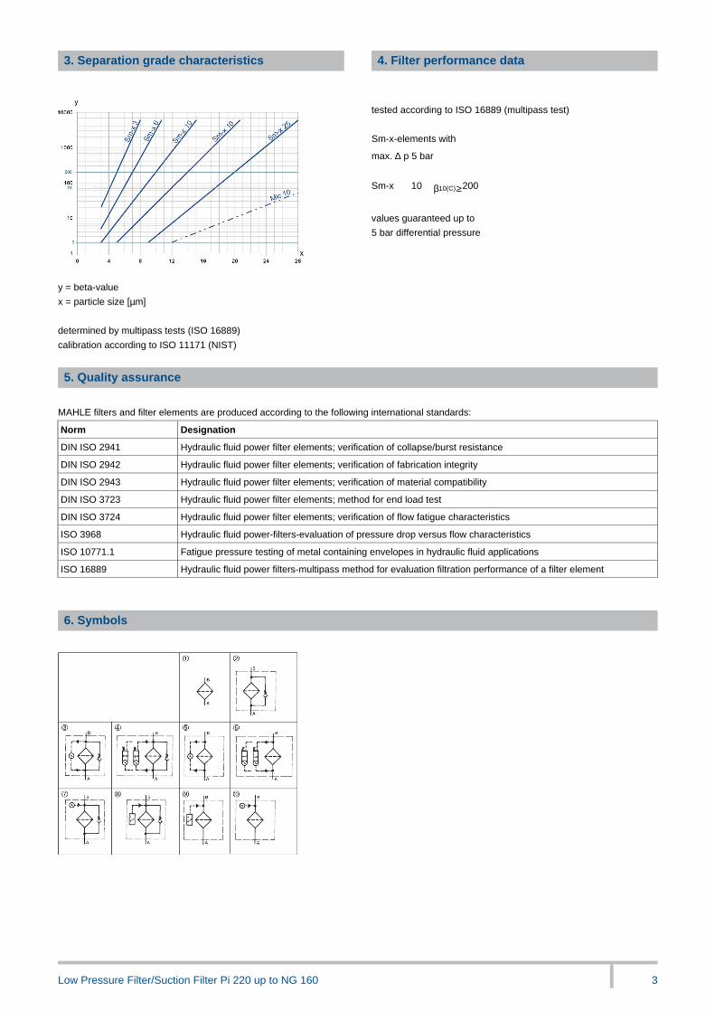
3. Separation grade characteristics
y = beta-value
x = particle size [µm]
_
determined by multipass tests (ISO 16889)
calibration according to ISO 11171 (NIST)
_
4. Filter performance data
-
tested according to ISO 16889 (multipass test)
-
Sm-x-elements with
max. ∆ p 5 bar
_
Sm-x 10 β10(C)≥200
-
values guaranteed up to
5 bar differential pressure
5. Quality assurance
MAHLE filters and filter elements are produced according to the following international standards:
Norm Designation
DIN ISO 2941 Hydraulic fluid power filter elements; verification of collapse/burst resistance
DIN ISO 2942 Hydraulic fluid power filter elements; verification of fabrication integrity
DIN ISO 2943 Hydraulic fluid power filter elements; verification of material compatibility
DIN ISO 3723 Hydraulic fluid power filter elements; method for end load test
DIN ISO 3724 Hydraulic fluid power filter elements; verification of flow fatigue characteristics
ISO 3968 Hydraulic fluid power-filters-evaluation of pressure drop versus flow characteristics
ISO 10771.1 Fatigue pressure testing of metal containing envelopes in hydraulic fluid applications
ISO 16889 Hydraulic fluid power filters-multipass method for evaluation filtration performance of a filter element
-
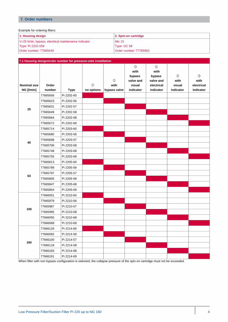
6. Symbols
Page 4
Low Pressure Filter/Suction Filter Pi 220 up to NG 160 4
7. Order numbers
Example for ordering filters:
1. Housing design 2. Spin-on cartridge
V=25 l/min, bypass, electrical maintenance indicator
Type: Pi 2202-058
Order number: 77665649
Mic 10
Type: OC 58
Order number: 77785983
_
7.1 Housing design/order number for pressure-side installation
Nominal size
NG [l/min]
Order
number Type no options
with
bypass valve
with
bypass
valve and
visual
indicator
with
bypass
valve and
electrical
indicator
with
visual
indicator
with
electrical
indicator
77665656 Pi 2202-60
77665623 Pi 2202-56
77665631 Pi 2202-57
77665649 Pi 2202-58
77665664 Pi 2202-68
25
77665672 Pi 2202-69
77665714 Pi 2203-60
77665680 Pi 2203-56
77665698 Pi 2203-57
77665706 Pi 2203-58
77665748 Pi 2203-68
40
77665755 Pi 2203-69
77665813 Pi 2205-60
77665789 Pi 2205-56
77665797 Pi 2205-57
77665805 Pi 2205-58
77665847 Pi 2205-68
63
77665854 Pi 2205-69
77666001 Pi 2210-60
77665979 Pi 2210-56
77665987 Pi 2210-57
77665995 Pi 2210-58
77666050 Pi 2210-68
100
77666068 Pi 2210-69
77666126 Pi 2214-60
77666092 Pi 2214-56
77666100 Pi 2214-57
77666118 Pi 2214-58
77666183 Pi 2214-68
160
77666191 Pi 2214-69
When filter with non bypass configuration is selected, the collapse pressure of the spin-on cartridge must not be exceeded.
Page 5
Low Pressure Filter/Suction Filter Pi 220 up to NG 160 5
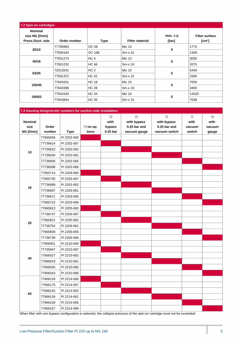
7.2 Spin-on cartridges
Nominal
size NG [l/min]
Press./Suct. side Order number Type Filter material
max. ∆ p
[bar]
Filter surface
[cm²]
77785983 OC 58 Mic 10 177525/10
77500184 OC 168 Sm-x 105
1309
77501273 HC 6 Mic 10 300040/16
77501232 HC 46 Sm-x 105
2075
72013241 HC 2 Mic 10 544063/25
77501372 HC 42 Sm-x 105
3360
77643331 HC 18 Mic 10 7000100/40
77643398 HC 28 Sm-x 105
3400
77504194 HC 34 Mic 10 14025160/63
77643844 HC 35 Sm-x 105
7638
7.3 Housing design/order numbers for suction-side installation
Nominal
size
NG [l/min]
Order
number Type
no op-
tions
with
bypass
0.25 bar
with bypass
0.25 bar and
vacuum gauge
with bypass
0.25 bar and
vacuum switch
with
vacuum
switch
with
vacuum
gauge
77665656 Pi 2202-060
77736614 Pi 2202-067
77736622 Pi 2202-062
77736630 Pi 2202-061
77736606 Pi 2202-065
10
77736598 Pi 2202-066
77665714 Pi 2203-060
77665730 Pi 2203-067
77736689 Pi 2203-062
77736697 Pi 2203-061
77736671 Pi 2203-065
16
77665722 Pi 2203-066
77665813 Pi 2205-060
77736747 Pi 2205-067
77665821 Pi 2205-062
77736754 Pi 2205-061
77665839 Pi 2205-065
25
77736739 Pi 2205-066
77666001 Pi 2210-060
77735947 Pi 2210-067
77666027 Pi 2210-062
77666019 Pi 2210-061
77666035 Pi 2210-065
40
77666043 Pi 2210-066
77666126 Pi 2214-060
77666175 Pi 2214-067
77666142 Pi 2214-062
77666134 Pi 2214-061
77666159 Pi 2214-065
63
77666167 Pi 2214-066
When filter with non bypass configuration is selected, the collapse pressure of the spin-on cartridge must not be exceeded.
Page 6
Low Pressure Filter/Suction Filter Pi 220 up to NG 160 6
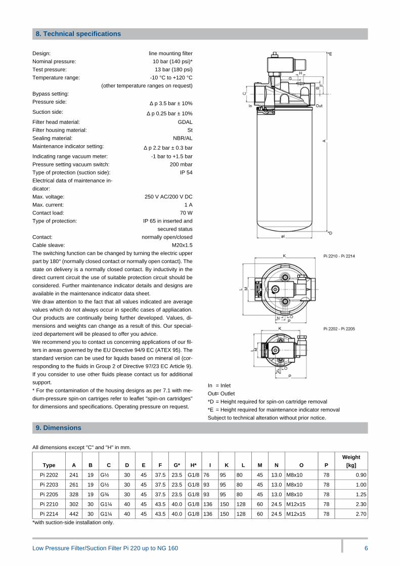
8. Technical specifications
Design: line mounting filter
Nominal pressure: 10 bar (140 psi)*
Test pressure: 13 bar (180 psi)
Temperature range: -10 °C to +120 °C
(other temperature ranges on request)
Bypass setting:
Pressure side: ∆ p 3.5 bar ± 10%
Suction side: ∆ p 0.25 bar ± 10%
Filter head material: GDAL
Filter housing material: St
Sealing material: NBR/AL
Maintenance indicator setting: ∆ p 2.2 bar ± 0.3 bar
Indicating range vacuum meter:
Pressure setting vacuum switch:
-1 bar to +1.5 bar
200 mbar
Type of protection (suction side): IP 54
Electrical data of maintenance in-
dicator:
Max. voltage: 250 V AC/200 V DC
Max. current: 1 A
Contact load: 70 W
Type of protection: IP 65 in inserted and
secured status
Contact: normally open/closed
Cable sleave: M20x1.5
The switching function can be changed by turning the electric upper
part by 180° (normally closed contact or normally open contact). The
state on delivery is a normally closed contact. By inductivity in the
direct current circuit the use of suitable protection circuit should be
considered. Further maintenance indicator details and designs are
available in the maintenance indicator data sheet.
We draw attention to the fact that all values indicated are average
values which do not always occur in specific cases of appliacation.
Our products are continually being further developed. Values, di-
mensions and weights can change as a result of this. Our special-
ized departement will be pleased to offer you advice.
We recommend you to contact us concerning applications of our fil-
ters in areas governed by the EU Directive 94/9 EC (ATEX 95). The
standard version can be used for liquids based on mineral oil (cor-
responding to the fluids in Group 2 of Directive 97/23 EC Article 9).
If you consider to use other fluids please contact us for additional
support.
* For the contamination of the housing designs as per 7.1 with me-
dium-pressure spin-on cartriges refer to leaflet "spin-on cartridges"
for dimensions and specifications. Operating pressure on request.
In = Inlet
Out= Outlet
*D = Height required for spin-on cartridge removal
*E = Height required for maintenance indicator removal
Subject to technical alteration without prior notice.
9. Dimensions
All dimensions except "C" and "H" in mm.
Type A B C D E F G* H* I K L M N O P
Weight
[kg]
Pi 2202 241 19 G½ 30 45 37.5 23.5 G1/8 76 95 80 45 13.0 M8x10 78 0.90
Pi 2203 261 19 G½ 30 45 37.5 23.5 G1/8 93 95 80 45 13.0 M8x10 78 1.00
Pi 2205 328 19 G¾ 30 45 37.5 23.5 G1/8 93 95 80 45 13.0 M8x10 78 1.25
Pi 2210 302 30 G1¼ 40 45 43.5 40.0 G1/8 136 150 128 60 24.5 M12x15 78 2.30
Pi 2214 442 30 G1¼ 40 45 43.5 40.0 G1/8 136 150 128 60 24.5 M12x15 78 2.70
*with suction-side installation only.
Page 7
Low Pressure Filter/Suction Filter Pi 220 up to NG 160 7
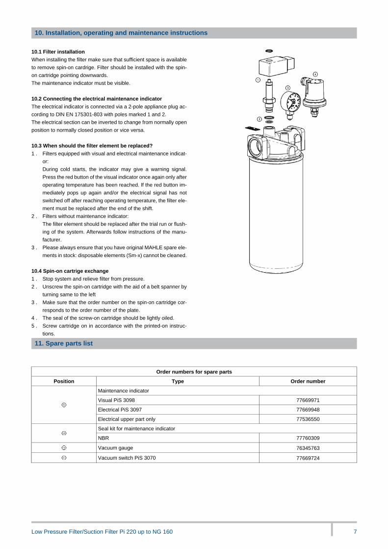
10. Installation, operating and maintenance instructions
10.1 Filter installation
When installing the filter make sure that sufficient space is available
to remove spin-on cardrige. Filter should be installed with the spin-
on cartridge pointing downwards.
The maintenance indicator must be visible.
-
10.2 Connecting the electrical maintenance indicator
The electrical indicator is connected via a 2-pole appliance plug ac-
cording to DlN EN 175301-803 with poles marked 1 and 2.
The electrical section can be inverted to change from normally open
position to normally closed position or vice versa.
-
10.3 When should the filter element be replaced?
1 . Filters equipped with visual and electrical maintenance indicat-
or:
During cold starts, the indicator may give a warning signal.
Press the red button of the visual indicator once again only after
operating temperature has been reached. lf the red button im-
mediately pops up again and/or the electrical signal has not
switched off after reaching operating temperature, the filter ele-
ment must be replaced after the end of the shift.
2 . Filters without maintenance indicator:
The filter element should be replaced after the trial run or flush-
ing of the system. Afterwards follow instructions of the manu-
facturer.
3 . Please always ensure that you have original MAHLE spare ele-
ments in stock: disposable elements (Sm-x) cannot be cleaned.
_
10.4 Spin-on cartrige exchange
1 . Stop system and relieve filter from pressure.
2 . Unscrew the spin-on cartridge with the aid of a belt spanner by
turning same to the left
3 . Make sure that the order number on the spin-on cartridge cor-
responds to the order number of the plate.
4 . The seal of the screw-on cartridge should be lightly oiled.
5 . Screw cartridge on in accordance with the printed-on instruc-
tions.
11. Spare parts list
Order numbers for spare parts
Position Type Order number
Maintenance indicator
Visual PiS 3098 77669971
Electrical PiS 3097 77669948
Electrical upper part only 77536550
Seal kit for maintenance indicator
NBR 77760309
Vacuum gauge 76345763
Vacuum switch PiS 3070 77669724
Page 8
Low Pressure Filter/Suction Filter Pi 220 up to NG 160 8
MAHLE Industriefiltration GmbH
Schleifbachweg 45
D-74613 Öhringen
Phone +49 7941 67-0
Fax +49 7941 67-23429
[email protected]
www.mahle.com
78356610.04/2015
![FreshHeavenMaxx GB · GEA Fresh Heaven j^uu ... Lp HEPA Power module Pre-filter Suction grille filter Suction chamber with fan Minimum Maximum Length of Power module Lp [mm] 500 Length](https://static.documents.pub/doc/80x56/5e430bff66247c5f7607f65d/freshheavenmaxx-gb-gea-fresh-heaven-juu-lp-hepa-power-module-pre-filter-suction.jpg)


