19
Low Probability of Intercept Radar Short Course on Radar and Electronic Warfare Kyle Davidson

Low Probability of Intercept Radar
Short Course on Radar and Electronic Warfare
Kyle Davidson

Seeing, without being seen…
• Low probability of intercept radar implies, that due to:– Low peak and average power
– Wide bandwidth
– Frequency or modulation variability
• The radar is difficult to intercept with a passive receiver
• Relies on antenna patterns, scan patterns, and wavefroms
Low Probability of Identification
• A radar that uses a specially emitted waveform intended to prevent a non-cooperative intercept receiver from intercepting and detecting its emission, but if intercepted, makes identification of the emitted waveform modulation and its parameters difficult
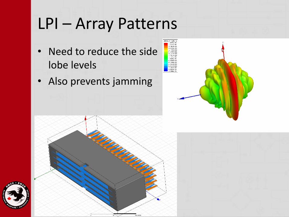
LPI – Array Patterns
• Need to reduce the side lobe levels
• Also prevents jamming

Array Amplitude Weighting
• Apply a amplitude distribution to the phased array elements
• Uniform => narrowest beam width
• Binomial => smallest side lobes
• Tschebyscheff => best compromise between side lobes and beam width
• LPI implies side-lobes below -45 dB

Binomial Array
1 + 𝑥 𝑚−1 = 1 + 𝑚 − 1 𝑥 +𝑚 − 1 𝑚 − 2
2!𝑥2 +⋯
M = 1 1
M = 2 1 1
M = 3 1 2 1
M = 4 1 3 3 1
M = 5 1 4 6 4 1
M = 6 1 5 10 10 5 1
⋮M = 10 1 9 36 84 126 126 84 36 9 1
Tschebyscheff Array
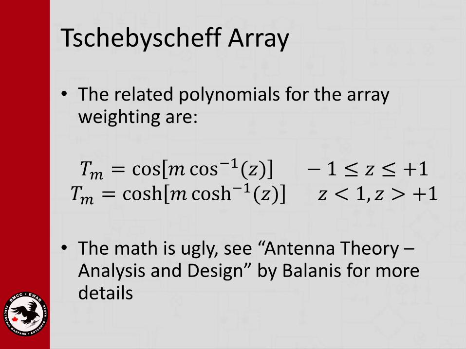
• The related polynomials for the array weighting are:
𝑇𝑚 = cos 𝑚 cos−1(𝑧) − 1 ≤ 𝑧 ≤ +1𝑇𝑚 = cosh 𝑚 cosh−1(𝑧) 𝑧 < 1, 𝑧 > +1
• The math is ugly, see “Antenna Theory –Analysis and Design” by Balanis for more details

Scan Patterns
• Raster Scan is very predictable
• LPI generally scan to limit the target illumination time to short, infrequent, and often unpredictable intervals
• Don’t be predictable!

Reducing Peak Power
• Move to a CW signal
𝑃𝑎𝑣𝑔 = 𝑃𝑡𝜏
𝑇

Power Management
• Why transmit at max power all the time?
– Don’t!
• Limit the power to the range and detection requirements

CW Requires Modulation!
• Linear or non-linear frequency modulation
• Phase modulation (PSK and Barker codes)
• Frequency hopping (FSK) and Costas arrays
• Combined frequency and phase modulation (FSK and PSK)
• Noise modulation
Pulse Compression
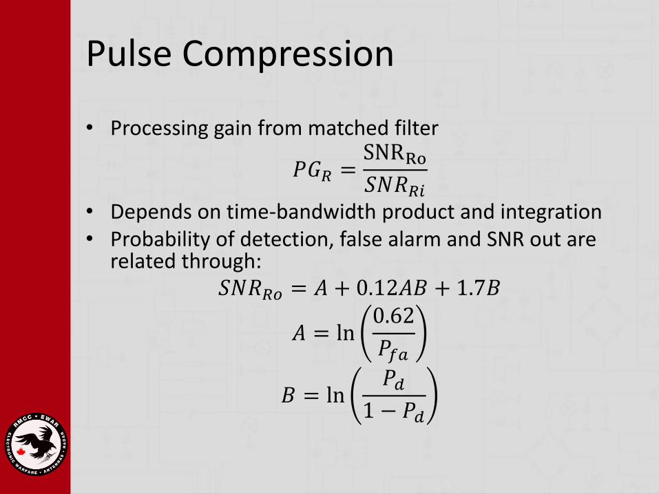
• Processing gain from matched filter
𝑃𝐺𝑅 =SNRRo𝑆𝑁𝑅𝑅𝑖
• Depends on time-bandwidth product and integration• Probability of detection, false alarm and SNR out are
related through:𝑆𝑁𝑅𝑅𝑜 = 𝐴 + 0.12𝐴𝐵 + 1.7𝐵
𝐴 = ln0.62
𝑃𝑓𝑎
𝐵 = ln𝑃𝑑
1 − 𝑃𝑑

Processing Gain
• For FMCW radars𝑃𝐺𝑅 = 𝑡𝑚Δ𝐹
• For non-coherent integration for 𝑁𝐼intervals the processing gain is increase by
𝑁𝐼
• For phase coded radars𝑃𝐺 = 𝑁𝑐
• where Nc is the number of subcodes

Who Sees Who First?
• Radar maximum detection range:
𝑅𝑚𝑎𝑥 =𝑃𝐶𝑊𝐺𝑡𝐺𝑟𝜆
2𝜎
4𝜋 3𝑘𝑇0𝐹𝑅𝐵𝑅𝑖 𝑆𝑁𝑅𝑅𝑖
1/4
• Interception range
𝑅𝐼𝑚𝑎𝑥=
𝑃𝐶𝑊𝐺𝑡′𝐺𝐼𝜆
2
4𝜋 2𝑘𝑇0𝐹𝐼𝐵𝐼 𝑆𝑁𝑅𝐼𝑖
1/2

LFM Waveform
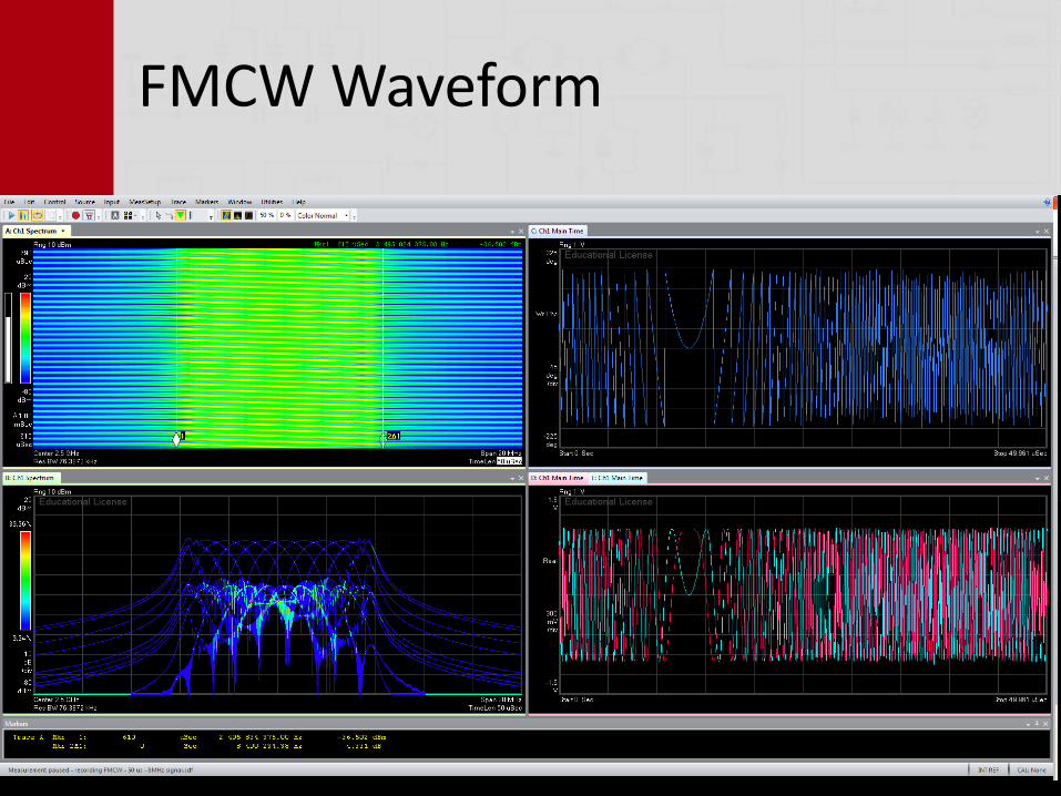
FMCW Waveform

Barker Code

3 Different LFM Pulses + Jitter
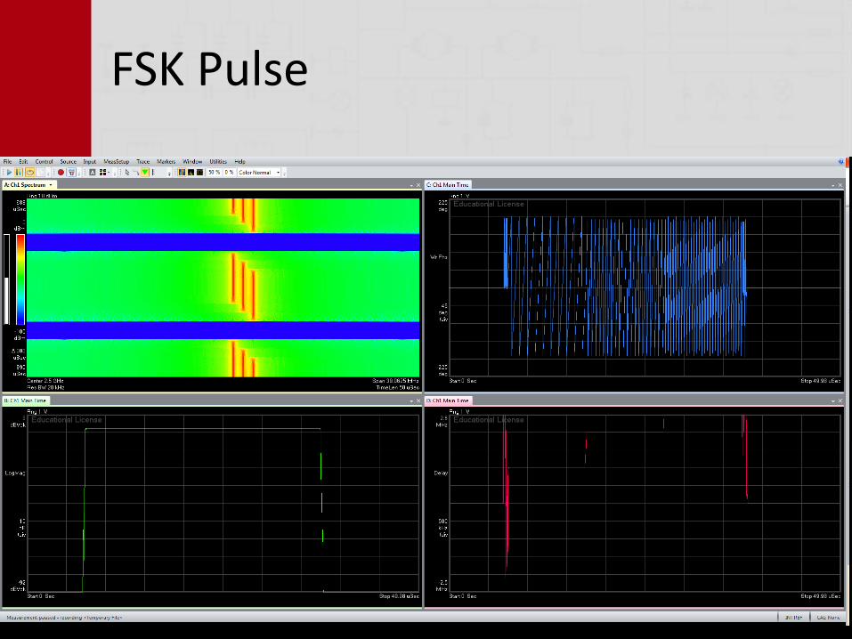
FSK Pulse


