52
LOW PROFILE PLANAR SPEAKER MOVING COIL Binh Phan, Ivanna Stuart, & Amile Zaaf

LOW PROFILE PLANAR SPEAKER
MOVING COIL Binh Phan, Ivanna Stuart, & Amile Zaaf

1
TABLE OF CONTENTS
Abstract 2
Acknowledgements 3
Introduction 4
Literature Review 6
Moving Magnet Research and Development 6
Rapid Injection Molding 8
Flat Panel Loudspeaker Design 9
Planer Speaker Design 10
How Planar Magnetic Drivers Work 11
Moving Coil Speaker 12
Moving Magnet Loudspeaker with Electronic Compensation 13
FEMM Modeling 14
Methodology 15
Procedure 15
Final Overall Design 27
Ansys Frequency Response 28
Conclusion 31
Recommendations for Future Work 33
References 34
Appendix 37

2
ABSTRACT
The goal of our team is to design a low profile speaker that has a high frequency response using a moving coil and a stationary
magnet. Our speakers will be a part of a low profile speaker system in which one team is designing a moving magnet speaker to play
bass frequencies, one team is designing the signal steering, one team is designing a panel and one team is designing double passive
radiator bass boxes. As the name refers, the total thickness of the speaker is less than 2.5 cm and the diameter is less than 10 cm.
Through research and the design process, we used different software to model and test the speaker such as Finite Element Method
Magnetic (FEMM), SolidWorks (CAD) and ANSYS (frequency response). We also used FEMM to optimize the steel frame and the
coil with a certain force/amp output. Our speaker features a double surround system, where one flexible rubber surround is stacked
above another, for increased stability. We also designed the speaker with integrated design for manufacturability features.

3
ACKNOWLEDGEMENTS
Our team would like to thank Professor Joe Stabile for making our MQP a reality and all of the effort that he put into helping us with
our project. This MQP would also not have been possible without the support and guidance from all of the following parties:
• Bose Corporation
• Worcester Polytechnic Institute
• Guy Torio
• Bill Berardi
• Jeff Copeland
• Binu Oommen
• Dan Sheehan
• Barbara Edilberti
• Dr. Erica Stults
• Washburn Shops
• Thomas Kouttron

4
INTRODUCTION
The need for this project arose from market desire to make an as thin as possible moving coil speaker with good quality sound. Our
goals for this project were to make a functional prototype of this speaker, but more specifically for our group to design a speaker using
a moving coil transducer. Our terms outline as follows: A term was for research and organization, B term was for designing and
realizing our prototype into hardware space, C term for further improving our design and prototype, and D term was for assembly.
In A term, after our first meetings we decided rather than all focusing on one task with our team of eighteen students, it would be more
efficient to run the team like a small company. We decided to split up into five teams, each focusing on a specific tasks with skill sets
of each student in mind. A form was created that each student was to submit and it was comprised of questions about what each
student would like to work on, in addition to what programs there were sufficient in using, along with any other skills one might have
such as machining. These questions were then reviewed by Professor Stabile and he formed the teams with these skill sets in mind as
to make the most balanced and effective teams.
After we formed our teams, goals were assigned to each team and it was decided that we should each focus on researching a particular
topic. Our team was designated to research moving magnet speaker design. We found a great series of insightful research papers about
this topic by a researcher named Razib Rashedin1 who did studies on thin planar speakers arranged in an array for efficiency and
compatibility, much like our objective 1. He influenced our design and we used his studies as a frequent reference. By the end of A
term, we had a wealth of knowledge and a firm plan of how we could tackle our team goal of producing an individual speaker
prototype.
5
In term B, we focused on getting into hardware space and settling on a design. We eventually chose to design a small moving coil type
speaker rather than a moving magnet type speaker and had the other design team go forward with a moving magnet design. We first
used a program called Finite Element Method Magnetics to simulate the dimensions of the magnet we were using in our speaker, in
this program we could apply currents on the magnet and observe the forces that would be produced. Once we designed our motor in
Finite Element Method Magnetics we made a 3D model of it in SolidWorks, then designed the support structure and diaphragm in that
program as well. Once all of our parts of the design were finalized, we went through the rapid prototyping procedure in Higgins
Laboratory to get our parts realized.
By the end of term B, we had a 3D printed speaker and the relevant magnets and coils as well, and we assembled 1 prototype
successfully. C and D term we spent manufacturing 8 of our designs, assembling them, and wiring them to our overall case.
6
LITERATURE REVIEW
At the beginning of the project, we were assigned to research moving magnet speakers but over the course of the term we were moved
into designing a moving coil speaker. This literature review is comprised of our initial research on both moving magnet and moving
coil speakers.
MOVING MAGNET RESEARCH AND DEVELOPMENT
Through preliminary research and investigation, we began to look into a moving magnet transducer. This involved preliminary
research to find out what exactly was a moving magnet transducer, how they were made, and how they function. Moving magnet
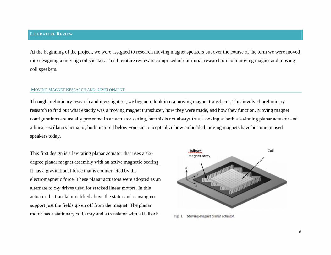
configurations are usually presented in an actuator setting, but this is not always true. Looking at both a levitating planar actuator and
a linear oscillatory actuator, both pictured below you can conceptualize how embedded moving magnets have become in used
speakers today.
This first design is a levitating planar actuator that uses a six-
degree planar magnet assembly with an active magnetic bearing.
It has a gravitational force that is counteracted by the
electromagnetic force. These planar actuators were adopted as an
alternate to x-y drives used for stacked linear motors. In this
actuator the translator is lifted above the stator and is using no
support just the fields given off from the magnet. The planar
motor has a stationary coil array and a translator with a Halbach
7
magnet array. The Halbach magnet has a strong magnetic field on one side and a weaker magnetic field on the other, as opposed to a
traditional magnet which has equally strong fields on both sides. The stator has 84 coils with concentrated windings and only 24 are
simultaneously energized. During movements in the x-y plane, the set of active coils changes with the position of the translator
because only the coils below and near the edge of the magnet array can produce significant force and torque. The best performing
topology in terms of power dissipation and force and torque ripples has been manufactured and successfully tested.
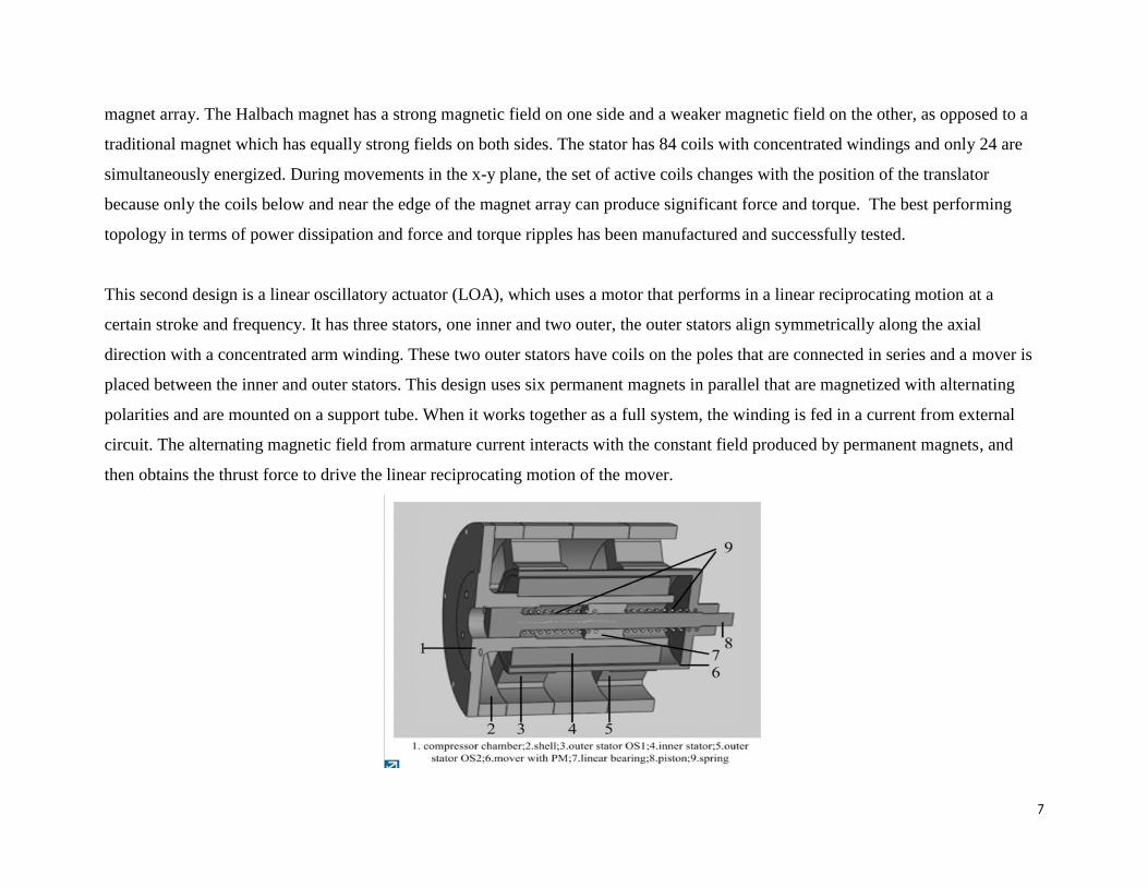
This second design is a linear oscillatory actuator (LOA), which uses a motor that performs in a linear reciprocating motion at a
certain stroke and frequency. It has three stators, one inner and two outer, the outer stators align symmetrically along the axial
direction with a concentrated arm winding. These two outer stators have coils on the poles that are connected in series and a mover is
placed between the inner and outer stators. This design uses six permanent magnets in parallel that are magnetized with alternating
polarities and are mounted on a support tube. When it works together as a full system, the winding is fed in a current from external
circuit. The alternating magnetic field from armature current interacts with the constant field produced by permanent magnets, and
then obtains the thrust force to drive the linear reciprocating motion of the mover.
8
RAPID INJECTION MOLDING
Using “The Smart Guide to Designing for Manufacturability” and “Fundamentals of Injection Molding Design” as a baseline for
initial research. We initially learned about the plastic injection molding process, advanced mold making systems, prototyping, wall
thickness and the importance of types of materials and resins in the process. The complexity of a molded design comes with
knowledge of ribs, tight tolerances, threads and undercuts. These articles delved into these CAD specific terms to encourage readers to
design molded parts with manufacturing processes in mind. By expanding my initial research, we began to research design for
manufacturability specifically for planar speakers looking at how magnetic planar speakers were built and gaining a better of
understand of current issues into planar speaker manufacturing. The purpose of this research is to allow our team to utilize the
weaknesses in current planar speaker designs to create a product that transforms current cost efficiency problems while still upholding
consistent design standards. When it comes to speakers a lot of new research is being developed around design for moldability for
rapid plastic injection molding. This is because by utilizing this technology the production time for molded products is bumped down
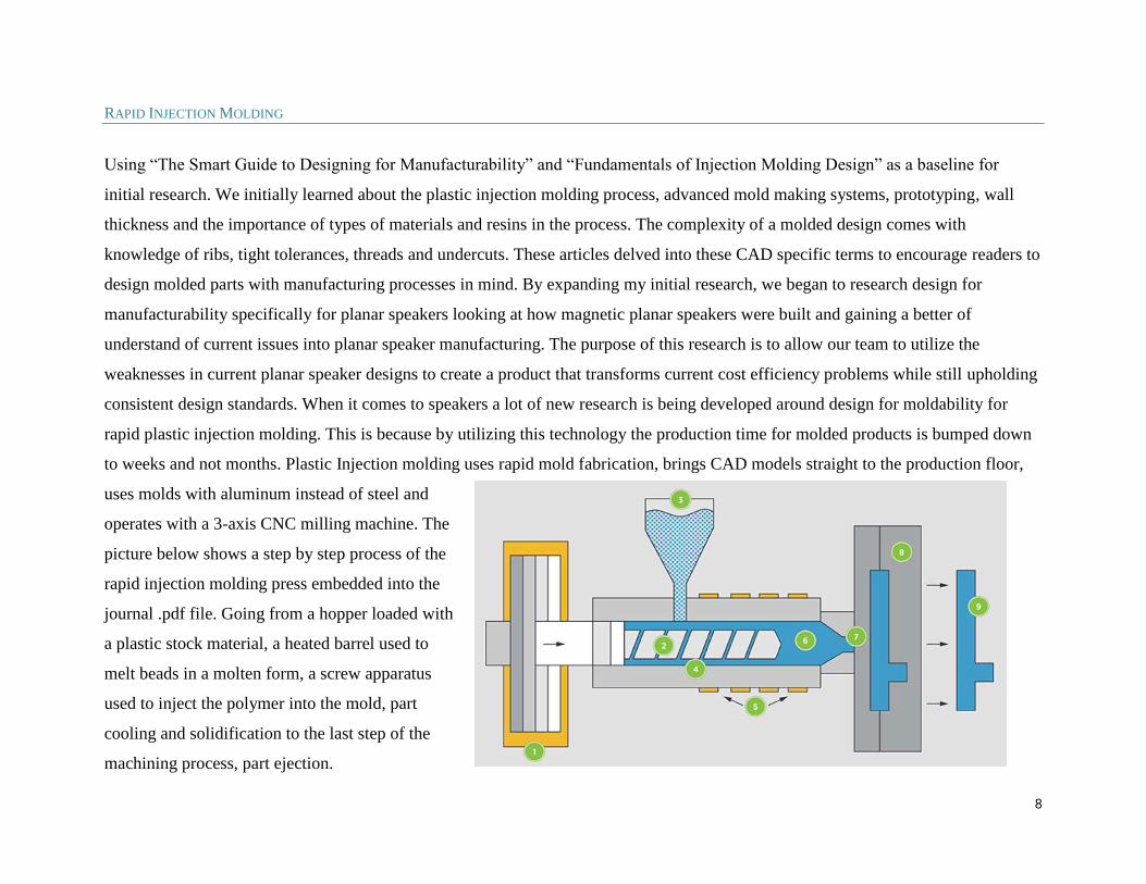
to weeks and not months. Plastic Injection molding uses rapid mold fabrication, brings CAD models straight to the production floor,
uses molds with aluminum instead of steel and
operates with a 3-axis CNC milling machine. The
picture below shows a step by step process of the
rapid injection molding press embedded into the
journal .pdf file. Going from a hopper loaded with
a plastic stock material, a heated barrel used to
melt beads in a molten form, a screw apparatus
used to inject the polymer into the mold, part
cooling and solidification to the last step of the
machining process, part ejection.
9
While rapid injection molding is used in a wide variety of fields we are looking at its application specifically in planar speakers.
Speaker technology at a basic level has not changed since the early to mid 1900s. It is the perfection of the design, electronic
components and manufacturing that has changed allowing for higher end, smaller, and overall more dynamic speaker systems. When
creating a speaker design, the designer has to take into consideration what makes the easiest way for the part to be fabricated.
“Fundamentals of Injection Molding Design” shows different techniques in the design stage to create an optimized part. Such as,
drafting to make easier for the ejecting of parts or what examples of a good screw boss looks like. The idea of creating a planar
speaker is simple, but for people working within the industry coming up with well thought out, cost efficient and precise design is
what may set you apart from other speaker companies and the yield with consumers. Part building at it core starts with a solid design
and while on the surface this may seem simple, it can become very complex. Design for Manufacturability takes into consideration
factors beyond looks and identifies a parts scope creep, bells and whistles, over design, sacred cows, basic requirements and unmet
customer needs to come up with the best possible part/ final product. With a limited sponsored budget and a demand for a successful
final product how this plays into our MQP is crucial. We are pushing to create a speaker that is optimized on all manufacturing
functions from fabrication to testing, as well as, keeping cost low enough to please the consumer.
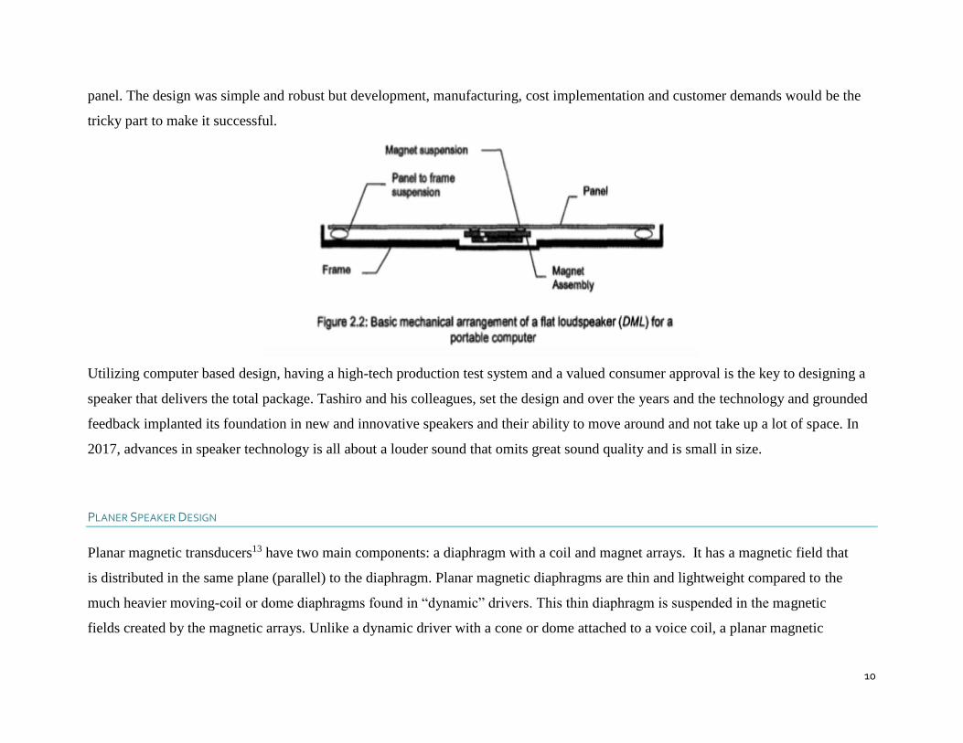
FLAT PANEL LOUDSPEAKER DESIGN
After reviewing “A New Flat Panel Loudspeaker for Portable Multimedia” 2, Mitch Tashiro and his team presented an innovative
speaker design in 1997. This design and many to come shaped the way we view speakers in our homes and how we interact with them
on the go. In his analysis, his team identified a Distributed Mode Loudspeaker (DML) that was a light-weight rigid flat panel type
broad band acoustic radiator that they hoped would be used in portable computers. Distributed Mode refers to flat panel speaker that
randomly generates vibrating nodes that produce output at different frequencies and amplitudes across the entire panel, with equal
output from both sides of the panel. In its simplest form, the magnets move when excited by a stationary coil, that is attached to the
10
panel. The design was simple and robust but development, manufacturing, cost implementation and customer demands would be the
tricky part to make it successful.
Utilizing computer based design, having a high-tech production test system and a valued consumer approval is the key to designing a
speaker that delivers the total package. Tashiro and his colleagues, set the design and over the years and the technology and grounded
feedback implanted its foundation in new and innovative speakers and their ability to move around and not take up a lot of space. In
2017, advances in speaker technology is all about a louder sound that omits great sound quality and is small in size.
PLANER SPEAKER DESIGN
Planar magnetic transducers13 have two main components: a diaphragm with a coil and magnet arrays. It has a magnetic field that
is distributed in the same plane (parallel) to the diaphragm. Planar magnetic diaphragms are thin and lightweight compared to the
much heavier moving-coil or dome diaphragms found in “dynamic” drivers. This thin diaphragm is suspended in the magnetic
fields created by the magnetic arrays. Unlike a dynamic driver with a cone or dome attached to a voice coil, a planar magnetic
11
diaphragm has a printed circuit spread across the surface of a thin-film substrate. When the circuit is energized with an audio signal
it interacts with the magnetic field and produces an electromagnetic force that moves the diaphragm back and forth creating sound.
HOW PLANAR MAGNETIC DRIVERS WORK
Consider a magnet with north and south poles, in planar magnetic drivers,14 these magnets are forced close to each other (with like
ends faced to each other causing the magnetic fields to squeeze) to create an array. The overlapped magnetic fields (also called
isodynamic fields) will be use to move the conductive traces of the diaphragm. The diaphragm is pushed or pulled by the moving of
conductive traces due to the push/pull forces by the magnetic field. The diaphragm is pushed when the magnetic flux arrows
opposed and pulled when magnetic flux arrows align. Hence the diaphragm moves up and down.
12
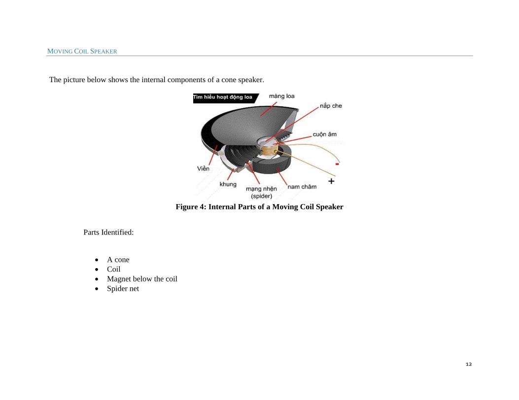
MOVING COIL SPEAKER
The picture below shows the internal components of a cone speaker.
Figure 4: Internal Parts of a Moving Coil Speaker
Parts Identified:
• A cone
• Coil
• Magnet below the coil
• Spider net
13
MOVING MAGNET LOUDSPEAKER WITH ELECTRONIC COMPENSATION
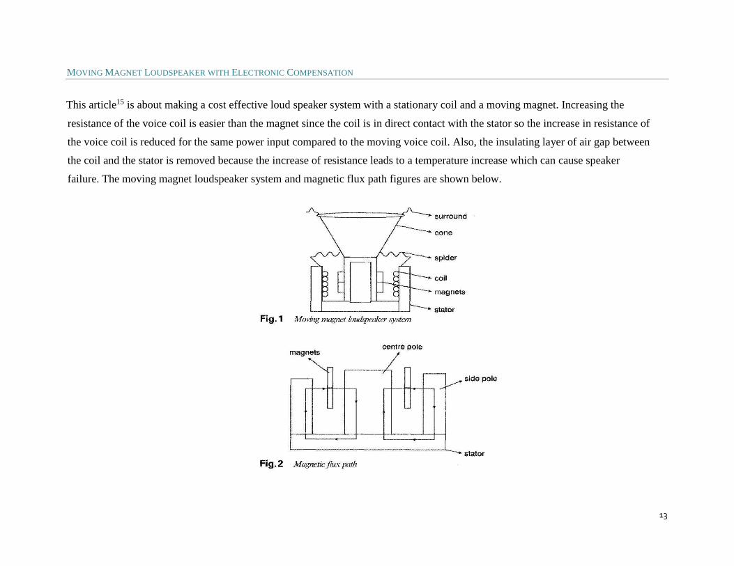
This article15 is about making a cost effective loud speaker system with a stationary coil and a moving magnet. Increasing the
resistance of the voice coil is easier than the magnet since the coil is in direct contact with the stator so the increase in resistance of
the voice coil is reduced for the same power input compared to the moving voice coil. Also, the insulating layer of air gap between
the coil and the stator is removed because the increase of resistance leads to a temperature increase which can cause speaker
failure. The moving magnet loudspeaker system and magnetic flux path figures are shown below.
14
FEMM MODELING
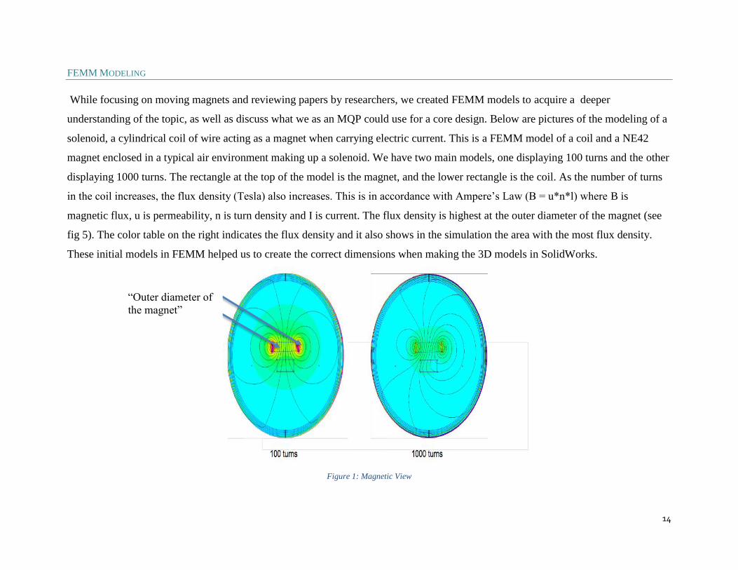
While focusing on moving magnets and reviewing papers by researchers, we created FEMM models to acquire a deeper
understanding of the topic, as well as discuss what we as an MQP could use for a core design. Below are pictures of the modeling of a
solenoid, a cylindrical coil of wire acting as a magnet when carrying electric current. This is a FEMM model of a coil and a NE42
magnet enclosed in a typical air environment making up a solenoid. We have two main models, one displaying 100 turns and the other
displaying 1000 turns. The rectangle at the top of the model is the magnet, and the lower rectangle is the coil. As the number of turns
in the coil increases, the flux density (Tesla) also increases. This is in accordance with Ampere’s Law (B = u*n*l) where B is
magnetic flux, u is permeability, n is turn density and I is current. The flux density is highest at the outer diameter of the magnet (see
fig 5). The color table on the right indicates the flux density and it also shows in the simulation the area with the most flux density.
These initial models in FEMM helped us to create the correct dimensions when making the 3D models in SolidWorks.
Figure 1: Magnetic View
“Outer diameter of
the magnet”

15
METHODOLOGY
Our goal was to design and create a low profile moving coil speaker bounded by specific restrictions, such as a 4N/amp output. We
accomplished this goal by utilizing FEMM (Finite Element Method Magnetics) and SolidWorks to design our prototype.
PROCEDURE
First, we made a 2D model in FEMM to see how the field lines formed and how much flux density we would get in order to find a
dimension for the speaker that wouldn’t saturate the field. After several 2D analysis’ we finally created our draft dimensions for the
speaker that we would go on to model using SolidWorks.
Figure 2: Flux Density
16
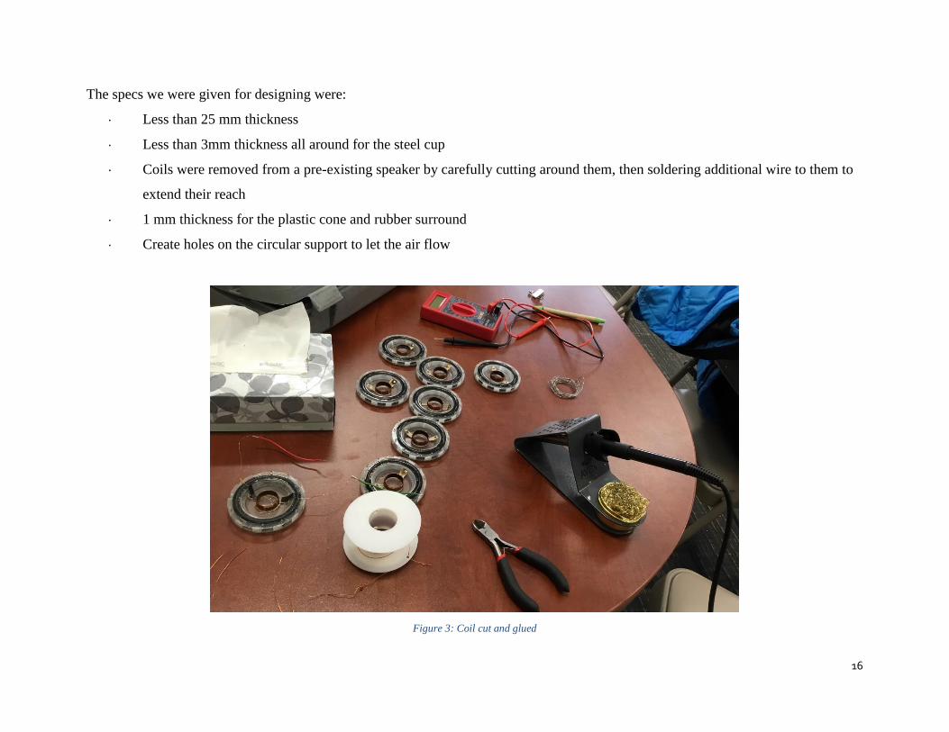
The specs we were given for designing were:
· Less than 25 mm thickness
· Less than 3mm thickness all around for the steel cup
· Coils were removed from a pre-existing speaker by carefully cutting around them, then soldering additional wire to them to
extend their reach
· 1 mm thickness for the plastic cone and rubber surround
· Create holes on the circular support to let the air flow
Figure 3: Coil cut and glued

17
Below are some images we captured of our first simulation in FEMM:
Figure 4: FEMM Analysis
-19N output
2 Amp current

18
After modeling in SolidWorks, we made some changes to the steel as well as designed the surround based on the instruction from our
advisor. These are some images of the parts we did in SolidWorks:
Figure 5: Top Support Design
19
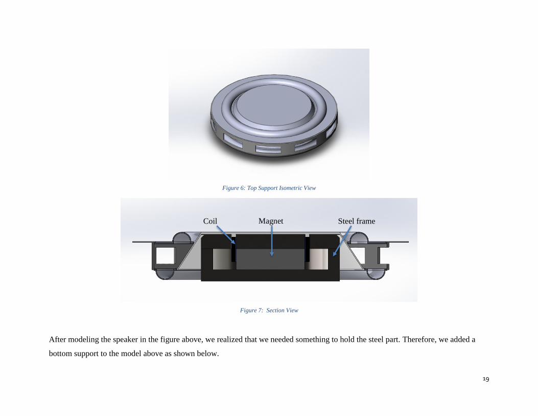
Figure 6: Top Support Isometric View
Figure 7: Section View
After modeling the speaker in the figure above, we realized that we needed something to hold the steel part. Therefore, we added a
bottom support to the model above as shown below.
Coil Magnet Steel frame

20
Figure 8: Completed Design Section View
Figure 9: Detailed View for Overlapping Material
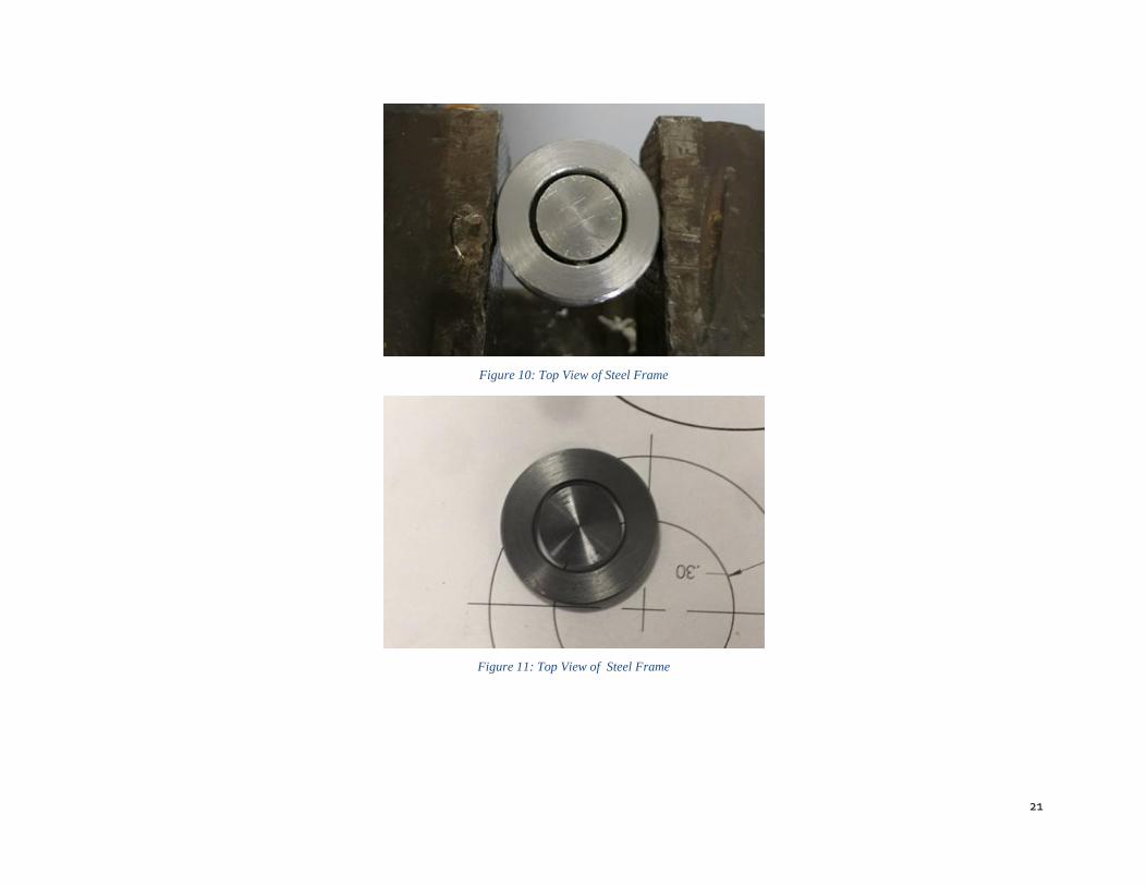
The plastic and rubber parts were 3D printed and the steel parts were CNC machined. Below are pictures of the steel parts that we
machined manually before going to the CNC machined for a faster manufacturing process.
“Bottom
Support”
21
Figure 10: Top View of Steel Frame
Figure 11: Top View of Steel Frame
22
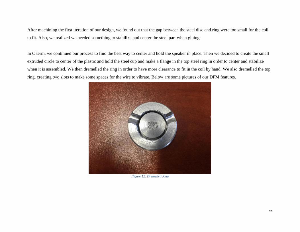
After machining the first iteration of our design, we found out that the gap between the steel disc and ring were too small for the coil
to fit. Also, we realized we needed something to stabilize and center the steel part when gluing.
In C term, we continued our process to find the best way to center and hold the speaker in place. Then we decided to create the small
extruded circle to center of the plastic and hold the steel cup and make a flange in the top steel ring in order to center and stabilize
when it is assembled. We then dremelled the ring in order to have more clearance to fit in the coil by hand. We also dremelled the top
ring, creating two slots to make some spaces for the wire to vibrate. Below are some pictures of our DFM features.
Figure 12: Dremelled Ring

23
Figure 13: Ring Bottom View with flange
Centering ring

24
Figure 14: Cup centering ring and axial hole to stabilize surround
Cup centering ring
Axial stablilizing hole
25
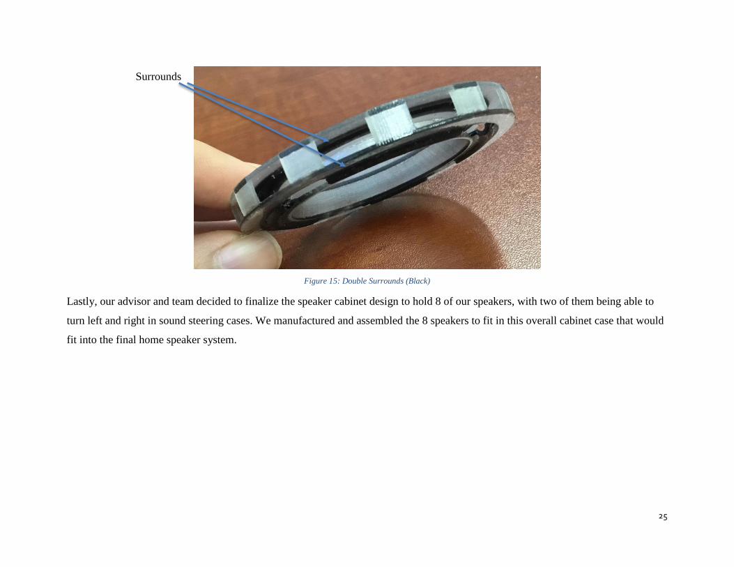
Figure 15: Double Surrounds (Black)
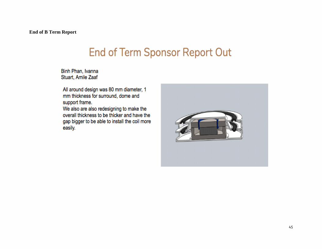
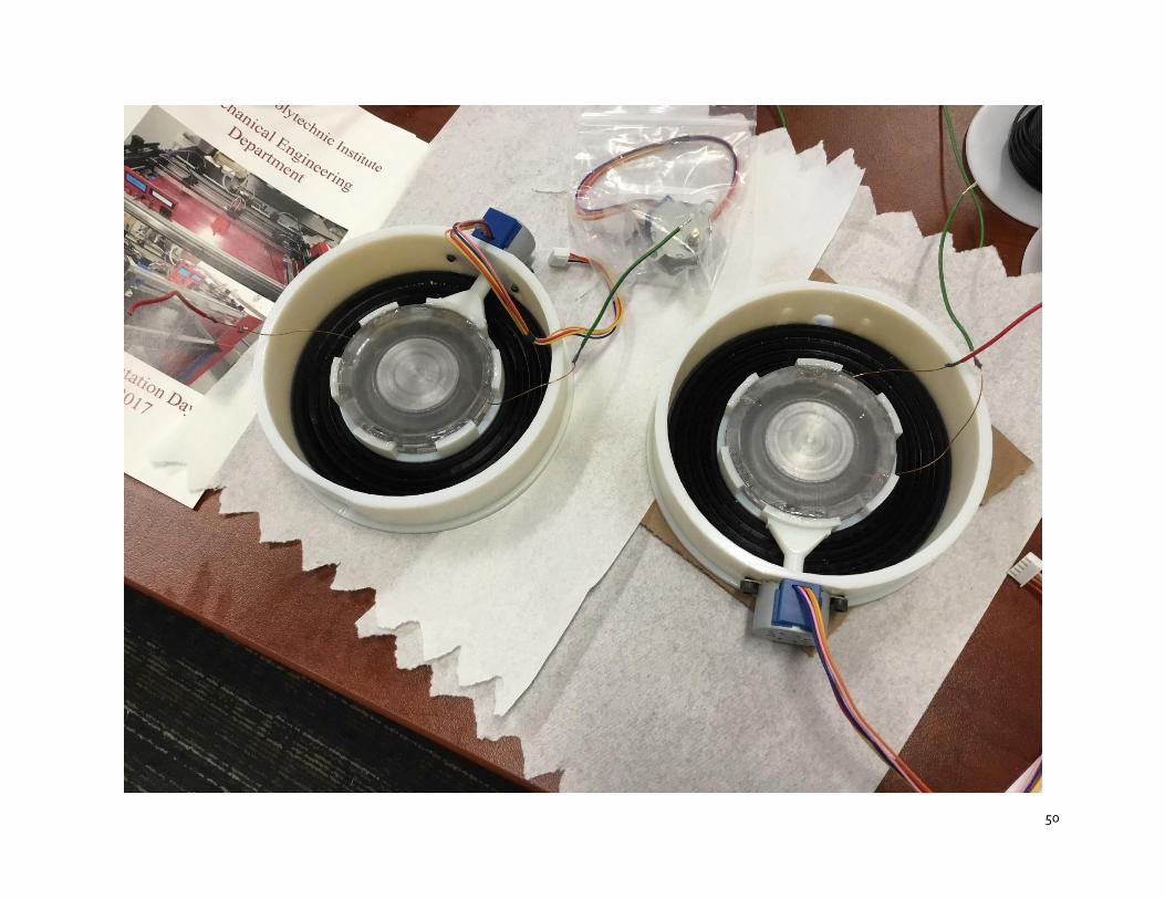
Lastly, our advisor and team decided to finalize the speaker cabinet design to hold 8 of our speakers, with two of them being able to
turn left and right in sound steering cases. We manufactured and assembled the 8 speakers to fit in this overall cabinet case that would
fit into the final home speaker system.
Surrounds
26
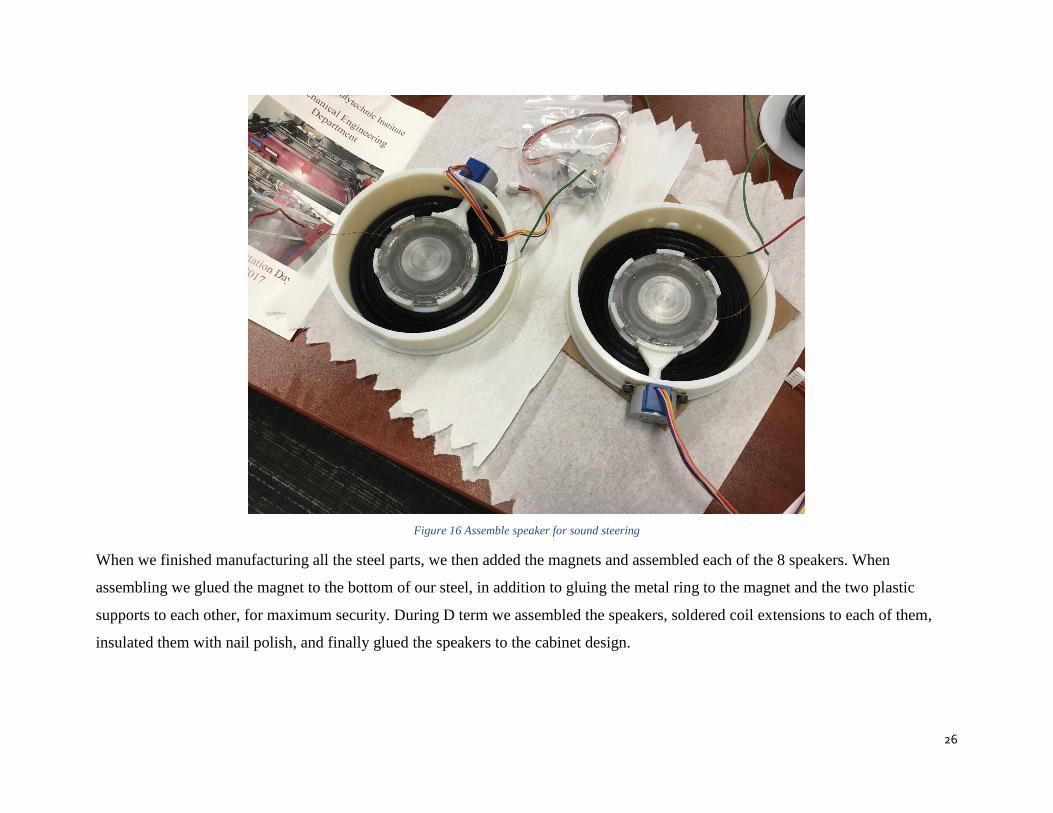
Figure 16 Assemble speaker for sound steering
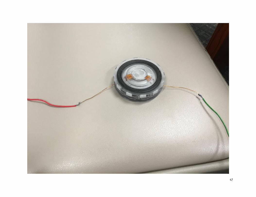
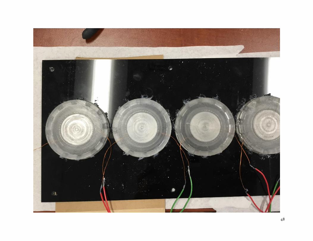
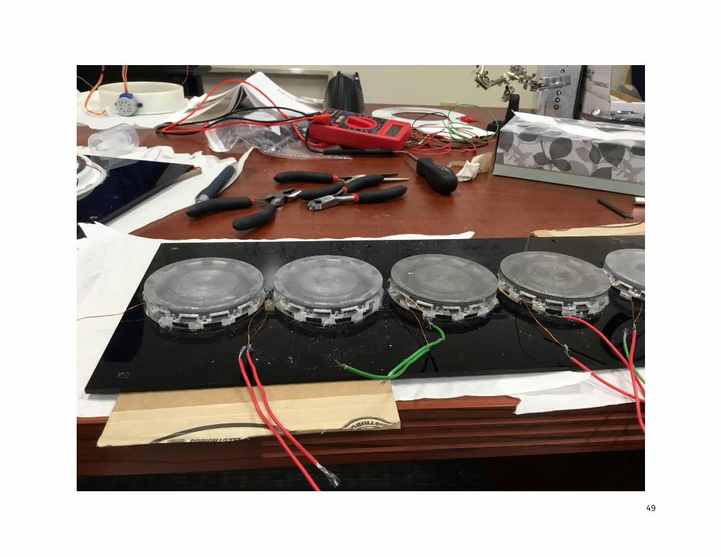
When we finished manufacturing all the steel parts, we then added the magnets and assembled each of the 8 speakers. When
assembling we glued the magnet to the bottom of our steel, in addition to gluing the metal ring to the magnet and the two plastic
supports to each other, for maximum security. During D term we assembled the speakers, soldered coil extensions to each of them,
insulated them with nail polish, and finally glued the speakers to the cabinet design.
27
FINAL OVERALL DESIGN
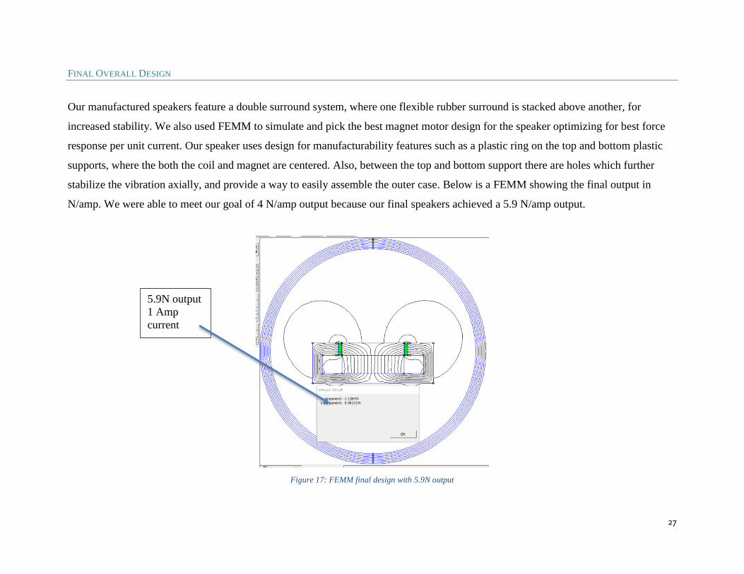
Our manufactured speakers feature a double surround system, where one flexible rubber surround is stacked above another, for
increased stability. We also used FEMM to simulate and pick the best magnet motor design for the speaker optimizing for best force
response per unit current. Our speaker uses design for manufacturability features such as a plastic ring on the top and bottom plastic
supports, where the both the coil and magnet are centered. Also, between the top and bottom support there are holes which further
stabilize the vibration axially, and provide a way to easily assemble the outer case. Below is a FEMM showing the final output in
N/amp. We were able to meet our goal of 4 N/amp output because our final speakers achieved a 5.9 N/amp output.
Figure 17: FEMM final design with 5.9N output
5.9N output
1 Amp
current
28
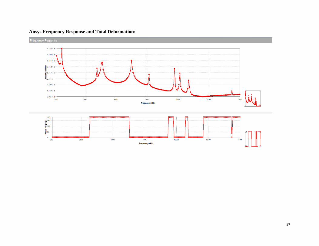
ANSYS FREQUENCY RESPONSE
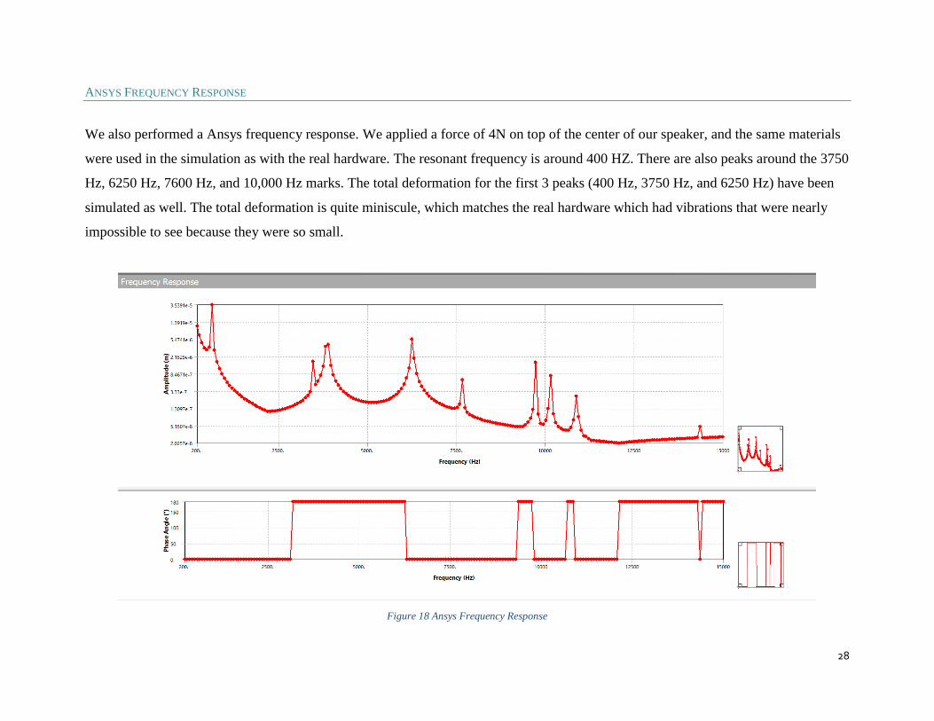
We also performed a Ansys frequency response. We applied a force of 4N on top of the center of our speaker, and the same materials
were used in the simulation as with the real hardware. The resonant frequency is around 400 HZ. There are also peaks around the 3750
Hz, 6250 Hz, 7600 Hz, and 10,000 Hz marks. The total deformation for the first 3 peaks (400 Hz, 3750 Hz, and 6250 Hz) have been
simulated as well. The total deformation is quite miniscule, which matches the real hardware which had vibrations that were nearly
impossible to see because they were so small.
Figure 18 Ansys Frequency Response

29
Figure 19 Ansys 400 Hz Total Deformation

30
Figure 20 Ansys 3750 Hz and 6250 Hz Total Deformation
31
CONCLUSION
Over the course of the school year, we have accomplished what we set out to produc:, a low profile speaker bounded by stringent
design specifications and requirements. We learned how important it is to design for manufacturability and that if you do not think
about this before you print or manufacture it can lead to a lot of issues with the assembly of your final product.
Discovered Issues
● Manufacturing takes a long time, and if not reproduced exactly leads to issues
● Design constraints
● Reproducibility and slight changes from speaker to speaker
● Tolerances and how each piece fits together
What is special about our speaker?
The thing that makes our speaker different from conventional a moving coil speaker is that we have a double surround system. Here,
our moving coil loudspeakers16 include a frame, a loudspeaker drive system, a cone, and a suspension system. The loudspeaker drive
system is fixed to the frame and includes a permanent magnet, a circular U-shape cup, an air gap and a voice coil. The voice coil is
fixed to the moving cone and arranged such that it is movable in the air gap in an axial up and down direction. The suspension system
is required to restore the driving force that the voice coil and the permanent magnet produce and comprises a second (lower) surround
that is 3D printed rigidly to the upper surround and the cone. In our design the lower surround acts exactly like the spider net in a
conventional moving coil speaker system. The lower surround is responsible for guiding the motion of the cone in the axial up and
down direction. The surround is made of rubber to achieve a low mechanical resistance in each direction desired with high damping
properties, while the lower surround provides the desired restoring forces required in the axial up and down direction. In a

32
conventional moving coil speaker, the spider is usually made from a woven fabric which is treated with a phenolic resin to stiffen the
spider, here we have a stiff enough rubber that can we didn’t need a spider net.
Advantages of our speaker versus other speakers:
● Easier to assemble since lower surround can be printed and integrated with the cone to make a rigid body
● The manufacturing of such spiders is labor intensive, highly variable, and, thus, very costly
33
RECOMMENDATIONS FOR FUTURE WORK
Through all the time we spent iterating and reassembling our speakers, we came up with various ways that could have improved our
design, however we did not have time to integrate them this year, these upgrades will be noted as recommendations for future work.
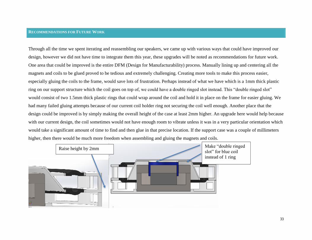
One area that could be improved is the entire DFM (Design for Manufacturability) process. Manually lining up and centering all the
magnets and coils to be glued proved to be tedious and extremely challenging. Creating more tools to make this process easier,
especially gluing the coils to the frame, would save lots of frustration. Perhaps instead of what we have which is a 1mm thick plastic
ring on our support structure which the coil goes on top of, we could have a double ringed slot instead. This “double ringed slot”
would consist of two 1.5mm thick plastic rings that could wrap around the coil and hold it in place on the frame for easier gluing. We
had many failed gluing attempts because of our current coil holder ring not securing the coil well enough. Another place that the
design could be improved is by simply making the overall height of the case at least 2mm higher. An upgrade here would help because
with our current design, the coil sometimes would not have enough room to vibrate unless it was in a very particular orientation which
would take a significant amount of time to find and then glue in that precise location. If the support case was a couple of millimeters
higher, then there would be much more freedom when assembling and gluing the magnets and coils.
Raise height by 2mm Make “double ringed
slot” for blue coil
instead of 1 ring
34
REFERENCES
(1) Analysis of a Moving Magnet Miniature Transducer Array Loudspeaker System
Rashedin,R,. Meydan,.” Analysis of a moving magnet miniature transducer array loudspeaker system” 2006.
https://www.researchgate.net/publication/251834520_Analysis_of_a_Moving_Magnet_Miniature_Transducer_Array_Loudspe
aker_System
(2)A New Flat Panel Loudspeaker for Portable Multimedia
Tashiro, M., Bank, G., & Roberts, M, “A New Flat Panel Loudspeaker for Portable Multimedia,” in 103rd AES Convention,
Sep 1997.
http://www.aes.org/e-lib/browse.cfm?elib=7252&turnmobile=on
(3) Moving Magnet Loudspeaker System with Electronic Compensation
K. A. Poomima and T. S. Hsu, "Moving magnet loudspeaker system with electronic compensation," in IEE Proceedings -
Circuits, Devices and Systems, vol. 148, no. 4, pp. 211-216, Aug 2001.
doi: 10.1049/ip-cds:20010348
http://ieeexplore.ieee.org.ezproxy.wpi.edu/stamp/stamp.jsp?tp=&arnumber=948393&isnumber=20520
(4) Magnetically Levitated Planar Actuator with Moving Magnets
J. W. Jansen, C. M. M. van Lierop, E. A. Lomonova and A. J. A. Vandenput, "Magnetically Levitated Planar Actuator With
Moving Magnets," in IEEE Transactions on Industry Applications, vol. 44, no. 4, pp. 1108-1115, July-aug. 2008.
35
doi:
10.1109/TIA.2008.926065.http://ieeexplore.ieee.org.ezproxy.wpi.edu/stamp/stamp.jsp?tp=&arnumber=4578793&isnumber=4
578767
(5) A Novel Transverse-Flux Moving-Magnet Linear Oscillatory Actuator
Y. Zhang, Q. Lu, M. Yu and Y. Ye, "A Novel Transverse-Flux Moving-Magnet Linear Oscillatory Actuator," in IEEE
Transactions on Magnetics, vol. 48, no. 5, pp. 1856-1862, May 2012.
doi:10.1109/TMAG.2011.2178077http://ieeexplore.ieee.org.ezproxy.wpi.edu/stamp/stamp.jsp?tp=&arnumber=6095369&isnu
mber=6187763
(6) Speaker Design and Manufacturing Best Practices. Digre, D., & Tatarunis, S. (2012, May). Retrieved September 14, 2017,
from http://misco.s3.amazonaws.com/press/speaker-design-best-practices.pdf
(7) Fundamentals of Injection Molding Design. Retrieved September 13, 2017, from
https://www.protolabs.com/resources/white-papers/designing-for-moldability-fundamental-elements/
(8) The Smart Guide to Designing for Manufacturability. Retrieved September 13, 2017, from
https://www.bing.com/cr?IG=D7BCA70FE99247FF8BAA204A3DB31B33&CID=3164E1C910436E3C3CCEEB3411456F3
E&rd=1&h=u8ko1yVoOTodCPKC8tBfDNTf6SM1Ums2XLbdZXLFGys&v=1&r=https%3a%2f%2fwww.xcentricmold.com
%2fdownloads%2fThe-Smart-Guide-to-Designing-For-Manufacturability.pdf&p=DevEx,5036.1
(9) Harris, M., & Nicholls, J. (2012). U.S. Patent No. US8295538B2. Washington, DC: U.S. Patent and Trademark Office.
36
(10) Robert, A. J. (1971). Maxi-Bass and Marvelous-Midi from Mini-Woof-Woof. Maxi-Bass and Marvelous-Midi from
Mini-Woof-Woof.
(11) Thiele, A. N., and R. H. Small. (1980). Vented Loudspeakers: an Anthology. Institution of Radio and Electronics
Engineers, Australia.
(12) Sweetwater. Damping Factor. (1997, November 11). Retrieved September 17, 2017, from
https://www.sweetwater.com/insync/damping-factor/
(13) Audeze. PLANAR MAGNETICS OVERVIEW. (2014, August 22). Retrieved September 17, 2017, from
https://www.audeze.com/technology/tech-tour/planar-magnetics-overview
(14) Tyll Hertsens. How Planar Magnetic Headphones Work. (2014, September 29). Retrieved September 17, 2017, from
https://www.innerfidelity.com/content/how-planar-magnetic-headphoneswork
(15) Poomima, K.A. and T. S. HSU. Moving magnet loudspeaker system with electronic compensation. (2001, August).
Retrieved October 02, 2017, from http://ieeexplore.ieee.org/document/948393/
(16) “US8295538B2 – Loudspeaker Spider.” Google Patents, Google, patents.google.com/patent/US8295538.
37
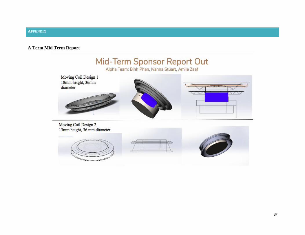
APPENDIX
A Term Mid Term Report

38
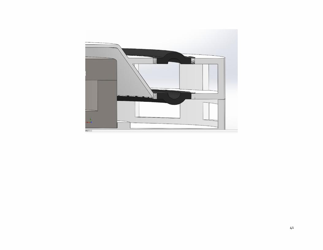
Improvement of Design through multiple iterations

39

40
41

42
Manufacturing Drawings for Magnet
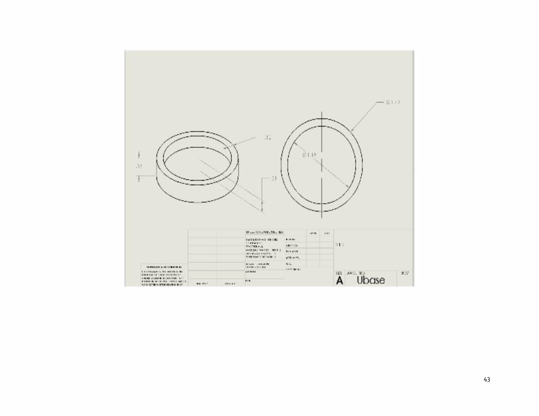
43
44
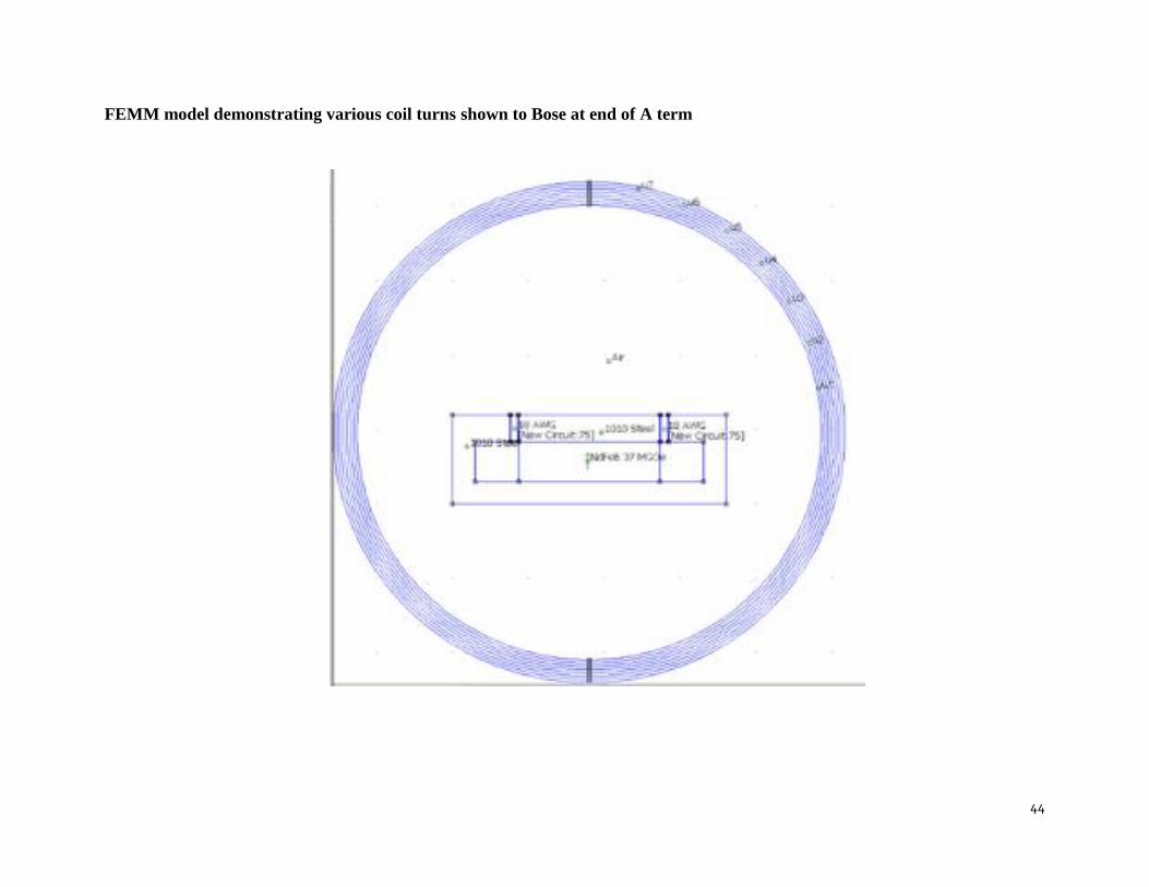
FEMM model demonstrating various coil turns shown to Bose at end of A term
45
End of B Term Report

46
Pictures of Manufactured Parts and Assembly
47
48
49
50
51
Ansys Frequency Response and Total Deformation:


