J. Fluid Mech. (1995), uol. 287, pp. 279-298 Copyright 0 1995 Cambridge University Press 279 Low Reynolds number motion of bubbles, drops and rigid spheres through fluid-fluid interfaces By MICHAEL MANGA'? AND H. A. STONE2 'Department of Earth and Planetary Sciences, Harvard University, Cambridge, MA 02138, USA 'Division of Applied Sciences, Harvard University, Cambridge, MA 021 38, USA (Received 16 June 1994 and in revised form 31 October 1994) The low Reynolds number buoyancy-driven translation of a deformable drop towards and through a fluid-fluid interface is studied using boundary integral calculations and laboratory experiments. The Bond numbers characteristic of both the drop and the initially flat fluid-fluid interface are sufficiently large that the drop and interface become highly deformed, substantial volumes of fluid may be entrained across the interface, and breakup of both interfaces may occur. Specifically, drops passing from a higher- to lower-viscosity fluid are extended vertically as they pass through the interface. For sufficiently large drop Bond numbers, the drop may deform continuously, developing either an elongating tail or enlarging cavity at the back of the drop, analogous to the deformation characteristic of a single deformable drop in an unbounded fluid. The film of fluid between the drop and interface thins most rapidly for those cases that the drop enters a more viscous fluid or has a viscosity lower than the surrounding fluids. In the laboratory experiments, bubbles entering a less viscous fluid are extended vertically and may break into smaller bubbles. The column of fluid entrained by particles passing through the interface may also break into drops. Further experiments with many rigid particles indicate that the spatial distribution of particles may change as the particles pass through interfaces : particles tend to form clusters. 1. Introduction The low Reynolds number motion of drops, bubbles and rigid particles passing through fluid-fluid interfaces occurs in a variety of industrial separation systems and naturally occurring density- and viscosity-stratified multiphase systems. A model problem, consisting of a single deformable drop approaching and passing through a deformable initially planar fluid-fluid interface, is considered in this paper, and extensions to multiple particle systems are discussed. Hereafter, we refer to the initially planar fluid-fluid interface as 'the interface'. Features of the model problem which are of interest include (1) the rate at which a drop passes through an interface, (2) the thickness of the film of fluid coating a drop as it passes through an interface, (3) whether a drop remains intact and connected or breaks into smaller drops, (4) the volume of fluid entrained by a drop as it passes through an interface, (5) the effect of the entrained fluid on the motion of additional drops through the t Now at Department of Geology and Geophysics, University of California, Berkeley. interface,
Transcript
J. Fluid Mech. (1995), uol. 287, p p . 279-298 Copyright 0 1995 Cambridge University Press
279
Low Reynolds number motion of bubbles, drops and rigid spheres through fluid-fluid interfaces
By MICHAEL MANGA'? AND H. A. STONE2 'Department of Earth and Planetary Sciences, Harvard University, Cambridge, MA 02138, USA
'Division of Applied Sciences, Harvard University, Cambridge, MA 021 38, USA
(Received 16 June 1994 and in revised form 31 October 1994)
The low Reynolds number buoyancy-driven translation of a deformable drop towards and through a fluid-fluid interface is studied using boundary integral calculations and laboratory experiments. The Bond numbers characteristic of both the drop and the initially flat fluid-fluid interface are sufficiently large that the drop and interface become highly deformed, substantial volumes of fluid may be entrained across the interface, and breakup of both interfaces may occur. Specifically, drops passing from a higher- to lower-viscosity fluid are extended vertically as they pass through the interface. For sufficiently large drop Bond numbers, the drop may deform continuously, developing either an elongating tail or enlarging cavity at the back of the drop, analogous to the deformation characteristic of a single deformable drop in an unbounded fluid. The film of fluid between the drop and interface thins most rapidly for those cases that the drop enters a more viscous fluid or has a viscosity lower than the surrounding fluids. In the laboratory experiments, bubbles entering a less viscous fluid are extended vertically and may break into smaller bubbles. The column of fluid entrained by particles passing through the interface may also break into drops. Further experiments with many rigid particles indicate that the spatial distribution of particles may change as the particles pass through interfaces : particles tend to form clusters.
1. Introduction The low Reynolds number motion of drops, bubbles and rigid particles passing
through fluid-fluid interfaces occurs in a variety of industrial separation systems and naturally occurring density- and viscosity-stratified multiphase systems. A model problem, consisting of a single deformable drop approaching and passing through a deformable initially planar fluid-fluid interface, is considered in this paper, and extensions to multiple particle systems are discussed. Hereafter, we refer to the initially planar fluid-fluid interface as 'the interface'. Features of the model problem which are of interest include
(1) the rate at which a drop passes through an interface, (2) the thickness of the film of fluid coating a drop as it passes through an interface, (3) whether a drop remains intact and connected or breaks into smaller drops, (4) the volume of fluid entrained by a drop as it passes through an interface, ( 5 ) the effect of the entrained fluid on the motion of additional drops through the
t Now at Department of Geology and Geophysics, University of California, Berkeley.
interface,
280 M . Manga and H . A . Stone
FIGURE 1. Different features characteristic of the motion of bubbles through fluid-fluid interfaces. The experimental results illustrate features ( 2 4 ) listed in the introduction. In (a) and (b) , a n air bubble translates through very viscous corn syrup towards a lower-viscosity layer of polyhutene (viscosity ratio between polybutene and corn syrup is 0.15). In (c) and (d), an air bubble translates through glycerin towards a higher-viscosity layer of polyhutene (viscosity ratio between polybutene and glycerin is 40). The four photographs presented above illustrate several of the features of the flow problem we consider. Complete sequences of photographs corresponding to (a,b) and (c ,d) are shown in figures 11 and 12, respectively.
(6) the effect of an interface on sedimenting suspensions. Here we consider the motion of drops and bubbles through an interface at small
Reynolds numbers,
(1.1) P Ua 92 = -41,
c1 where U is the rise speed of the drop, a is a characteristic dimension of the drop, i.e. the drop radius, and p and p are the density and viscosity of the fluid surrounding the drop, respectively. In the present study we are concerned with the limit in which large interface distortions occur to either the drop, the interface, or both fluid-fluid interfaces. For a fluid-fluid interface characterized by a density difference Ap, large distortions occur when the Bond number is large,
a=- Apga2 > 0(1), 0
where 0 is the interfacial tension and g is the gravitational acceleration. Typically, in engineering applications, ,49 > 1 corresponds to particle radii greater than a few millimetres. However, large Bond numbers are also characteristic of systems with miscible fluids or low values of interfacial tensions such as the interfacial tension between oils with similar chemical compositions. The large Bond number motion of drops and bubbles through interfaces may also be relevant to understanding the ascent of mantle plumes or descent of subducted slabs through the Earth’s mantle (e.g. Manga, Stone & O’Connell 1993).
Several previous detailed studies of this class of flow/free-boundary problems have been numerical, though limited to modest interface distortions: Lee & Leal (1982) and
Low Reynolds number motion of particles through fluid-fluid interfaces 281
Geller, Lee & Leal (1986) studied the motion of a rigid sphere towards and through a deformable interface; Chi & Leal (1989) studied the motion of a deformable drop towards its homophase (a fluid layer with the same chemical composition as the drop); Pozrikidis (1990b) and Ascoli, Dandy & Leal (1990) studied the motion of a drop normal to a flat rigid surface, and Koch & Koch (1995) studied the motion of a drop normal to a flat free-slip surface. Finite Reynolds number influences were studied numerically by Shopov & Minev (1992). Published experimental research on the low Reynolds number motion of drops through interfaces has also been limited to drops and bubbles approaching their homophase and rigid spheres passing through interfaces (see summaries in Chi & Leal 1989 and Geller et al. 1986). Approximate analytical results for a sphere translating normal and parallel to a deformable, though nearly planar, interface were developed by Lee & Leal (1982) using perturbation methods. A combination of lubrication theory and boundary integral methods was used by Yiantsios & Davis (1990) to study the close approach of a nearly spherical deformable drop to a nearly flat deformable interface. A significant contribution of these studies is the illustration of the complete evolution of the particle-interface interaction including the details of film drainage.
In figure 1 we present four photographs from two different experiments in order to highlight different aspects of the complete evolution of a bubble-interface interaction; the four photographs are selected from complete sequences of photographs shown in figures 11 and 12 in 5 4. In the experiments shown in figure l(a,b), an air bubble translates in very viscous corn syrup (B = lop3) towards and through a less dense, lower-viscosity layer of polybutene. In figure l(a) we observe that the bubble is extended vertically as it passes through the interface. In figure l(b) we show a photo- graph, taken at a later time, in which the large bubble has broken into smaller bubbles, and a long narrow column of the more dense lower fluid has been entrained across the interface. In the experiments shown in figure l(c,d), an air bubble translates through glycerin (B = 1) towards a higher-viscosity layer of polybutene. In figure l(c) a thin layer of glycerin coats the air bubble as it passes through the interface. In figure l(d) we show a photograph, taken at a later time, in which the entrained column of glycerin has broken into a sequence of smaller drops by a capillary (Rayleigh) instability.
The four photographs presented in figure 1 illustrate several features of the mul- tiphase flow problem including large deformation, penetration into the upper layer, breakup, and entrainment. Boundary integral numerical simulations presented in 6 3 allow us to consider a wide range of model parameters, extend previous numerical studies to the long-time and large deformation limit for drops penetrating interfaces, and obtain quantitative details of the flow. In 4 we consider the entire evolution of the interface as a bubble or rigid sphere passes through the interface. The experimen- tal results allow us to obtain insight into dynamics following breakup; in particular we study breakup of both the drop and interface (e.g. figure 1). The numerical and experimental results of 5 3 and 5 4 are used in 5 5 to explain the motion of several rigid spheres and bubbles through fluid-fluid interfaces.
2. Problem formulation The motion of a drop passing through a stably stratified fluid-fluid interface is
modelled by considering three fluid domains, as shown in figure 2. The boundary integral method is used to numerically study the free-boundary flow problem. We denote the three fluid domains by subscripts 1, 2 and 3 for the lower fluid, the drop, and the upper fluid, respectively. For completeness we summarize the basic equations.
282
YP P - 4 3
M. Manga and H . A. Stone
Fluid 3 (upper fluid)
FIGURE 2. Geometry of the dropinterface problem. The initially planar fluid-fluid interface is referred to as the interface. The unit normal vector n is outward from the drop and directed into the lower fluid away from the interface. In the calculations the initial position of the drop is h = 4a below the initially flat interface S2.
In the low Reynolds number limit the flow in each fluid domain satisfies the Stokes
(2.1) where u is the fluid velocity, p is the fluid pressure, T is the modified stress tensor defined to incorporate the body force pg, i.e. 7 = -PI+ p[Vu + (VU)~] + pg . XI, x is the position vector, p is the fluid viscosity, and the subscript i denotes fluids 1, 2 or 3. As the stress tensor T is defined to be divergence free, the body force pg thus appears in the boundary conditions, equations (2.5) and (2.6) below.
and continuity equations
V . Ti = piV2ui - Vpi + pig = 0 and V . ui = 0,
We require that the velocity decays to zero far from the drop,
u1 -+ 0 as 1x1 -+ co, (2.2)
u3 -+ 0 as 1x1 -+ co, and that the velocity is continuous across all interfaces,
u2 = u1 on S1 and u3 = u1 on S2, (2.4) where S1 is the surface bounding the drop and S2 is the interface. The stress jump [n . T I i across interface Si is balanced by the stresses arising from density contrasts and interface curvature V, . n:
(2.5)
(2.6) where ci denotes the constant interfacial tension, n is the unit normal directed into the lower fluid, and V, = ( I - nn) * V is the gradient operator tangent to the interface. Additionally there is a kinematic constraint, expressed with the Lagrangian description
[n . T I , = n . T1 - n . T2 = g1 (V, . n)n + nAp2g . x, x E S1
En . T I 2 = n. 71 - n . T3 = g2 (V, . n)n + nAp3g . X, x E S2,
dx = u(x), x E S1 and S2. (2.7) -
dt
Low Reynolds number motion of particles through fluid-fluid interfaces 283
The equations are made dimensionless by choosing the characteristic length as the undeformed drop radius a, the velocity scale as Ap2ga2/p and an advective timescale as p/Ap;?ga. For a given initial configuration (dimensionless separation distance h / a in figure 2), five dimensionless parameters characterize the flow: the viscosity ratios, A and y indicated in figure 2, two Bond numbers
and a buoyancy parameter, defined as
The dimensionless Hadamard-Rybczynski rise speed in the lower fluid is 3(31 + 2)/2( 1 + A) and in the upper fluid is 3(3A + 2y)( 1 - jJ)/2(A+ y). The frequently studied problem of a drop approaching its homophase corresponds to 1 = y , 991 = 992 and p = 1 (e.g. Chi & Leal 1989). For p > 1 the drop will spread beneath the interface. The limit of p,>l and y = 0 is studied by Koch & Koch (1995). We are interested in f l < 1 so that the drop passes through the interface and large interface distortions occur.
Stokes equations may be recast as integral equations for the interfacial velocities u(x) for x E S, ,S2 . The integral representations for the velocity, and associated integral equations for the interfacial velocities for a system containing two fluid-fluid interfaces, are given by (Tanzosh, Manga & Stone 1992)
En. T I l . J dSy - (1-1) J n . K . u dSy - 111.. T I 2 . J dS, s1
(2.10)
where J and K are known kernels for velocity and stress, respectively, and y is the integration variable.
The interfacial velocities are determined by solving equation (2.10) using standard numerical collocation procedures and the time-dependent motion of the interface is determined using the kinematic condition (2.7). For the axisymmetric configuration studied in 0 3, the azimuthal integration may be performed analytically (Lee & Leal 1982) reducing (2.10) to a line integral. Integrations are performed using Gauss- Legendre quadrature. The interface shapes are described by taut cubic splines (de Boor 1978) parameterized in terms of arc length. Both fluid-fluid interfaces are represented numerically by 100 collocation points which are uniformly distributed on the drop, but concentrated on the interface in regions where the separation distance from the drop is small. Calculations are continued until the separation distance between the interfaces is smaller than the distance between collocation points along either interface. In the physical system, non-hydrodynamic forces due to electrostatic or intermolecular effects typically become important for separation distances less than about 10 nm. In the numerical solution of the boundary integral equations, the
284 M. Manga and H . A. Stone
(a) A = 10 (b) A = 1 (c) a = 0.1
FIGURE 3. Effect of changing the ratio of drop to lower fluid viscosity for 1 = 10, 1 and 0.1; y = 0.1, /l = 0.2, Bl = 20 and B2 = a.
initially planar interface, S2, is truncated at a distance of 15 drop radii from the axis of symmetry. Results computed for an interface that extends to distances between 10 and 50 drop radii show very little variation. A more detailed discussion of the effects of interface truncation is given by Lee & Leal (1982). Further details of the numerical approach are given by Manga (1994).
3. Results Below we present numerically calculated results for the buoyancy-driven motion of
a deformable drop through a fluid-fluid interface. We begin in 9 3.1 by presenting typical interface shapes at different times and proceed to discuss four specific features characteristic of the dynamics: mode of drop deformation (0 3.2), drop rise speed (9 3.3), increase of drop surface area (9 3.4), and the rate of drainage of fluid between the drop and interface (9 3.5). In all cases, we consider the motion of the drop through an interface in the limit of large distortions, a limit not previously studied.
3.1. Drop and interface deformation 3.1.1. Changing 1, the ratio of drop to lowerjuid viscosity
In figure 3 we consider the effect of changing the viscosity ratio 1, the ratio of drop to lower fluid viscosity, on the translation of a drop through an interface. We present simulations for 1 = 10, 1 and 0.1; y = 0.1, p = 0.2, L271 = 20 and L272 = 00.
As the viscosity ratio 1 decreases, the magnitude of drop deformation at a given height above the interface increases. The rate at which the drop passes through the interface increases with decreasing 1. Furthermore, the viscosity ratio J. affects the rate of drainage of the film of fluid which surrounds the drop. In particular, for A = 10, the drop entrains a thick and nearly spherical shell of the lower fluid, whereas for 1 < 0(1) the drop entrains only a thin layer of the lower fluid. If the drop is sufficiently deformable, simulations with il = 1 and 0.1, the drop becomes extended as it enters the upper lower-viscosity fluid since the rise speed of the drop in the upper fluid is larger than in the lower fluid (recall that the Hadamard-Rybczynski rise speed for an isolated drop is inversely proportional to the viscosity of the external fluid and proportional to the density difference with the external fluid). For an isolated
Low Reynolds number motion of particles through fluid-fluid interfaces 285
t = 100
A
(a) y = 10 (b) y = 1 (c) y = 0.1
FIGURE 4. Effect of changing the ratio of upper to lower fluid viscosity for y = 10, 1 and 0.1 ; 1 = 1, a = 0.2, CBl = 20 and CB2 = co.
drop, the time scale for deformation scales approximately as 1/(1 + A) (Rallison 1984; Kojima, Hinch & Acrivos 1984) so that the 1 = 10 high viscosity ratio drop experiences significantly less distortion than the drops in the other simulations.
3.1.2. Changing y, the ratio of upper to lowerfluid viscosity
In figure 4 we consider the effect of changing the viscosity ratio y, the ratio of upper to lower fluid viscosity, on the translation of a drop through a fluid interface. We present simulations for y = 10, 1 and 0.1; A = 1, p = 0.2,Bl = 20 and B2 = co. Drops accelerate as they enter the lower-viscosity upper fluid and are extended (acceleration in a quasi-steady Stokes flow is permitted owing to a change in geometry, but does not contribute to the local force balance in the fluid). The extension continues and may lead to the breakup of the drop, which is examined further in Q 4. Drops decelerate as they enter a higher-viscosity upper fluid and develop a dimple or small cavity at the back of the drop. Careful examination of figure 4 reveals that for a given A, the volume of lower fluid entrained increases with decreasing y.
3.1.3. Changing Bl and $92
In figures 5 and 6 we consider the effect of changing the interfacial tension forces relative to buoyancy forces, corresponding to varying the parameters gAl and B2. Recall that increasing interfacial tension, or decreasing B, typically decreases the magnitude of interface deformation. In figure 5 we vary the Bond number of the drop; 31 = 2, 5, 20 and 100, A = 1, y = 0.1, p = 0.2, and 8 2 = 00. The rate at which the drop passes through the interface changes very little even though the shapes are different.
In figure 6 we change the Bond number of the interface; B2 = 5, 20 and 100, A = 1, y = 0.1, p = 0.2, and B1 = 20. Not surprisingly, increasing B2 increases the rate at which the drop passes through the interface. For the B2 = 5 simulation, a dimple or indentation develops at the back of the drop. Notice that at t = 40 the film thickness is approximately the same for all the simulations (figures 5 and 6) indicating
FIGURE 5. Effect of changing gl for g1 = 2, 5, 20 and 100; 1 = 1, y = 0.1, = 0.2, and 5?2 = co.
0 lo
(a) 99, = 5 (b) 99, = 20 (c) w, = 100
FIGURE 6. Effect of changing .4?2 for = 5, 20 and 100; 1 = 1, y = 0.1, = 0.2, and 99, = 20.
that the rate of film drainage is controlled by the fluid viscosity ratios and is largely independent of and 9?2 for the limits studied here.
3.2. Modes of drop deformation Studies by Kojima et al. (1984), Koh & Leal (1989, 1990) and Pozrikidis (1990~) demonstrated that translating non-spherical drops at low Reynolds numbers are unstable if the interfacial tension stresses are not sufficiently large to return the drop to a spherical shape. The shape is unstable in the sense that the drop may deform continuously with two possible modes of deformation:
(1) An initially prolate drop becomes further elongated, the front of the drop develops a nearly spherical shape, and the back of the drop forms an ever-elongating tail, which may eventually break into a series of smaller droplets due to a capillary instability.
Low Reynolds number motion of particles through jluid-Juid interfaces 287
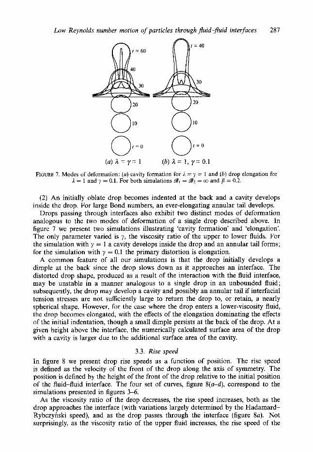
(a) a = y = 1 (b) a = 1 , y = 0.1
FIGURE 7. Modes of deformation: (a ) cavity formation for 1 = y = 1 and (b ) drop elongation for 1 = 1 and y = 0.1. For both simulations 931 = 932 = co and = 0.2.
( 2 ) An initially oblate drop becomes indented at the back and a cavity develops inside the drop. For large Bond numbers, an ever-elongating annular tail develops.
Drops passing through interfaces also exhibit two distinct modes of deformation analogous to the two modes of deformation of a single drop described above. In figure 7 we present two simulations illustrating ‘cavity formation’ and ‘elongation’. The only parameter varied is y, the viscosity ratio of the upper to lower fluids. For the simulation with y = 1 a cavity develops inside the drop and an annular tail forms; for the simulation with y = 0.1 the primary distortion is elongation.
A common feature of all our simulations is that the drop initially develops a dimple at the back since the drop slows down as it approaches an interface. The distorted drop shape, produced as a result of the interaction with the fluid interface, may be unstable in a manner analogous to a single drop in an unbounded fluid; subsequently, the drop may develop a cavity and possibly an annular tail if interfacial tension stresses are not sufficiently large to return the drop to, or retain, a nearly spherical shape. However, for the case where the drop enters a lower-viscosity fluid, the drop becomes elongated, with the effects of the elongation dominating the effects of the initial indentation, though a small dimple persists at the back of the drop. At a given height above the interface, the numerically calculated surface area of the drop with a cavity is larger due to the additional surface area of the cavity.
3.3. Rise speed In figure 8 we present drop rise speeds as a function of position. The rise speed is defined as the velocity of the front of the drop along the axis of symmetry. The position is defined by the height of the front of the drop relative to the initial position of the fluid-fluid interface. The four set of curves, figure 8(a-d), correspond to the simulations presented in figures 3-6.
As the viscosity ratio of the drop decreases, the rise speed increases, both as the drop approaches the interface (with variations largely determined by the Hadamard- Rybczynski speed), and as the drop passes through the interface (figure 8a). Not surprisingly, as the viscosity ratio of the upper fluid increases, the rise speed of the
288 M . Manga and H . A. Stone
1 .o
0.8
a 8 0.6 9 0 .P 0.4 d
0.2
0
0.5
0.4
W 8 0.3 9 .P 0.2 d
0.1
0
0
-2 0 2 4
-2 0 2 4 Position
0.5
0.4
0.3
0.2
0.1
0
a2 = 5
-2 0 2 4
0.5
0.4
0.3
0.2
0.1
" -2 0 2 4 Position
FIGURE 8. Rise speed of the top of the drop as a function of the position of the top of the drop. Results correspond to figures 3-6: (a) L = 10, 1 and 0.1 with y = 0.1, p = 0.2, Bl = 20, 932 = co, ( b ) 691 = 5, 20 and 100 with I = 1, y = 0.1, p = 0.2, B2 = co, ( c ) = 5, 20 and 100 with I = 1, y =0.1, p =0.2, $81 = 20, and ( d ) y = 10, 1 and 0.1 with I = 1, p =0.2, B1 = 20, B2 = a.
drop decreases (figure 8d). In the limit where the drop attains a (nearly) steady shape far from the boundary, we expect the rise speed to approach a steady state determined largely by the Hadamard-Rybczynski value with some modification due to entrained fluid. For large Bond numbers the drop becomes highly deformed and may not achieve a steady shape. The numerical method does not allow us to study the motion of drops to sufficient distances through the interface that the asymptotic rise speed is approached.
Changing the interfacial tension of the drop for large Bond numbers (981 > 5) does not significantly affect the rise speed (figure 8b). As the interfacial tension of the interface is increased, i.e. as B2 is decreased, the rise speed of the drop decreases (figure 8c). In particular, the minimum rise speed decreases as B2 decreases. However, as the drop moves away from the interface, smaller values of ,982 result in faster rise speeds due to an enhanced constriction of the interface around the extended drop (compare the curves in figure 8c for B = 5 with the curve for positions greater than 4).
For a wide range of parameters, the drops reach a minimum rise speed when the front of the drop is at a distance of about 0.5 to 2.5 drop radii above the initial position of the fluid-fluid interface. We observe in figure 8(a) that low viscosity drops reach their minimum rise speed at a shorter distance past the initial interface position than high-viscosity ratio drops because the rate of film drainage is greater and the drops deform more rapidly. The reason drops reach a minimum rise speed above
Low Reynolds number motion of particles through Juid-Juid interfaces 289
13
-4 -2 0 2 4 -4 -2 0 2 4 Position Position
FIGURE 9. Surface area of drop as a function of the height of the top of the drop. Results correspond to figures 3 and 4: (a) 1 = 10, 1 and 0.1 with y = 0.1, p = 0.2, Bl = 20, g2 = 00, and ( b ) y = 10, 1 and 0.1 with 1 = 1, fi = 0.2, Bl = 20, B2 = co.
the interface is that interface deformation results in additional forces resisting drop translation : ‘negative’ buoyancy forces associated with the dense lower fluid displaced vertically and interfacial tension forces. The latter are typically small for 972 > O( 1).
3.4. Drop surface area In figure 9 we present the drop surface area for the simulations presented in figures 3 and 4. For the case of drops entering a lower-viscosity upper fluid, figure 9(a), at a given height above the interface the surface area is larger for drops with low viscosity ratios A. Since the rate of deformation scales approximately as 1/(1 + A) while the drop approaches the interface and as l / ( y + A) while the drop moves away from the interface (i.e. the largest viscosity sets the timescale for deformation), drops with a low viscosity ratio deform faster than drops with a high viscosity ratio.
The effect of y is shown in figure 9(b). First we consider the simulation with y = 10 which has a maximum in the surface area. The drop’s surface area increases as the drop approaches the interface as a result of the drop spreading and flattening, and then decreases as the drop passes through the interface. While passing through the interface, the drop becomes more spherical (figure 4a) and the surface area decreases even though a cavity is forming.
Next we compare the simulations with y = 1 and 0.1. The cavity which develops for y = 1 results in a slightly increased surface area compared to the simulation with y = 0.1 for positions less than 3a. As the drops continue to pass through the interface, the effect of elongation for y = 0.1 results in a greater increase in surface area than the simulation with y = 1.
3.5. Gap thickness We next consider the rate at which the film drains for large Bond numbers and /? < 1. Figure 10 illustrates the evolution of the gap thickness for the simulations presented in figures 3-6. We note that film drainage has been a primary focus of many previous investigations, e.g. the limit p = 1 has been studied numerically by Chi & Leal (1989) for 0.9 < g < 45, and analytically by Yiantsios & Davis (1990) for BGl. Chi & Leal demonstrated that drops approaching their homophase may develop a dimpled mode of film drainage; dimples may form under similar conditions for two translating drops (Manga & Stone 1993). However, for the range of parameters considered here, namely large Bond numbers, gi > 5, a dimple is not observed to form. We suggest
290 M . Manga and H . A. Stone
" - 1 0 1 2 3 4 5 " - 1 0 1 2 3 4 5
1 .o
0.8
0.6
0.4
0.2
0
Position Position FIGURE 10. Gap thickness h / a between the top of the drop and the interface along the axis of symmetry. Results correspond to figures 3-6: (a) 1 = 10, 1 and 0.1 with y = 0.1, p = 0.2, 93'1 = 20, 93'2 = co, ( b ) 91 = 5, 20 and 100 with 1 = 1, y = 0.1, p = 0.2,92 = co, (c) 93'2 = 5, 20 and 100 with 1 = 1, y = 0.1, p = 0.2, 93'1 = 20, and (d) y = 10, 1 and 0.1 with 1 = 1, f i = 0.2, 98, = 20, 93'2 = 00.
that since the drops are passing through the interface, p < 1, the continual translation of the drops prevents the formation of a dimple. Using the nomenclature of Chi & Leal (1989), only uniform and rapid drainage occur. Yiantsios & Davis (1991) found that dimples always form for B-el.
The results presented in figure 10(a) indicate that at a given position, the film of fluid coating the drop is thinnest for low viscosity ratio drops. As drops with a high viscosity ratio enter a lower-viscosity fluid (y < 1) they become coated with a thick layer of the lower fluid (the simulation with 1 = 10 in figure 3) since high-viscosity drops act to retard film drainage whereas low-viscosity drops provide little resistance to film drainage. Comparing film thickness for a drop at a given position above the interface, a thinner film develops as 282 decreases (figure 1Oc) and y increases (figure 10d) since in both cases the drop translates more slowly and more time exists for film drainage. The Bond number of the drop has little effect on film drainage for moderate to large Bond numbers, Bl > 5 (figure lob).
4. Experimental results Owing to limitations of the numerical approach employed in 9 3, in particular the
numerical difficulty resolving thin films separating two distinct phases, there are a number of features we could not consider fully, for example, (i) the break-off of the
Low Reynolds number motion of particles through fluid-fluid interfaces 29 1
drop from the interface which requires the interfacial-tension-driven constriction of the thin column of fluid entrained by the rising drop, (ii) the breakup of the drop as it is extended when passing from a higher to lower viscosity fluid, and (iii) the motion of multiple particles through an interface. In this section we consider experimentally the long-time evolution of the different fluid phases as bubbles and rigid spheres pass through fluid-fluid interfaces. The numerical procedure employed in tj 3 allows us to consider only 0.1 < i < 10, thus the experiments extend the results to the limits iel and i+l.
4.1. Experimental apparatus The experiments are performed in a rectangular glass tank with a height of 19 cm, and a base 15 cm x 31 cm. The tank was filled with either corn syrup (bottom) and polybutene (top), or glycerin (bottom) and polybutene (top). The corn syrup was coloured with red food colouring in order to enhance the visual contrast between the two fluid layers. The Reynolds numbers 92 characteristic of the translation of bubbles and particles are small in corn syrup and polybutene, 92 < 0.05, but in glycerin may be as large as 92 = O(O.l-1). An estimate of the interfacial tension between corn syrup and polybutene and between glycerin and polybutene was determined using the pendant drop technique (Fordham 1948). We measured ~7 = 0.028 0.006 N m-l for corn syrup and polybutene and ~7 = 0.022 & 0.004 N m-l for glycerin and polybutene. The error estimates are based on measurement uncertainties. The ‘relaxing drop method’ (Tjahjadi, Stone & Ottino 1994) was also used to confirm the pendant drop results, and provided similar results, but with larger experimental uncertainties.
Typical bubble and particle radii are 1 cm. Thus in the experiments wall and boundary effects should be small so that boundary effects should have little qualitative influence on the experimental results presented below.
4.2. A single bubble passing through an interface In figures l(a,b) we presented photographs of the translation of an air bubble through an interface and into a less-viscous fluid. In figure 11 we present the complete sequence of experimental observations, and focus on the deformation of the air bubble. As the bubble approaches the interface it becomes slightly oblate or flattened. Notice that the bubble has a small tail in the first photograph. Owing to the large viscosity of the corn syrup and finite thickness of the layer of corn syrup, the tail initially formed as the bubble is released into the tank does not relax before reaching the interface. The bubble passes through the interface and becomes extended, forms a long tail and drags a long narrow column of the more dense and more viscous lower fluid across the interface. The long tail of air then breaks off from the bubble, leaving a highly distorted dumbbell-shaped bubble, which eventually breaks again to form two smaller bubbles (indicated by the arrows in the last photograph). Notice that in the final photographs, the two small bubbles have moved downwards, which results from the relaxation of the deformed interface due to downflow of the heavy entrained fluid.
The general features of the experimental results at earlier times are similar to the numerical results shown in figure 3 for the simulation with A = 0.1; in particular note the bubble shape and the distinctive dimple at the back. In the numerical calculations the film of fluid between the drop and interface eventually becomes too thin to allow us to qualitatively compare the experimental and numerical results for times longer than those shown in figure 3. We note that the breaking of the air column, 241, occurs via thinning into a narrow thread which appears to develop an even thinner secondary thread. In pendant drop experiments, Shi, Brenner & Nagel (1994)
292 M . Manga and H . A . Stone
FIGURE 11. Air bubble passing from a higher- to lower-viscosity fluid. Times and a scale bar are shown on the photographs. The upper fluid is polybutene, the lower fluid is corn syrup; 1 = 0, y = 0.15, Bl = 45, B2 = 40 and /l = 0.37. The Reynolds number is < in the lower fluid and < 0.05 in the upper fluid. The characteristic time p / A p * g a = 1.2 s.
observed a cascade of shape transitions involving a sequence of repeated neckings from an original thread shape; Shi et al.’s observations appear similar to the thread evolution in figure 11, although in their experiments b l and inertial effects are not negligible.
In figure l(c,d) we presented photographs of the motion of an air bubble through an interface and into a more viscous fluid. In figure 12 we present the complete sequence of experimental observations, and focus on the thin column of the lower fluid entrained through the interface by the rising bubble. The Reynolds number based on the lower fluid viscosity (glycerin) characteristic of the motion of the bubble towards the interface is 92 fi: 1. The Reynolds number based on the upper fluid viscosity (polybutene) characteristic of the motion of the bubble through and past the interface is smaller, 92 < 0.01. At a distance about 10 radii above the interface, the bubble breaks off from the lower fluid. The column of the lower fluid entrained by the bubble undergoes a Rayleigh or capillary instability and breaks up into smaller drops. The droplets consisting of the lower fluid then sediment and eventually coalesce with the lower fluid. We note that the thin film coating the bubble at t = 3 s has a nearly constant thickness, which is the uniform drainage mode (Chi & Leal 1989), and a dimple is never observed.
Low Reynolds number motion of particles through fluid-fluid interfaces 293
FIGURE 12. An air bubble passing from a lower- to higher-viscosity fluid. Times and a scale bar are shown on the photographs. The upper fluid is polybutene, the lower fluid is glycerin; 1 = 0, y = 0.02, = 4, 332 = 3.4 and /3 = 0.27. The Reynolds number is = 1 in the lower fluid and < in the upper fluid. The characteristic time p / A p z g a = 0.012 s.
FIGURE 13. A teflon sphere passing from a higher- to lower-viscosity fluid. Times and a scale bar are shown on the photographs. The upper fluid is polybutene, the lower fluid is glycerin; /z = a, y = 40, 992 = 1.4 and /3 = 0.23. The Reynolds number is < in the upper fluid and < 0.1 in the lower fluid. The characteristic time p / A p z g a = 0.75 s.
In figure 13 we examine the motion of a rigid teflon sphere sedimenting through an interface into a lower-viscosity fluid. The sphere remains coated with a thick layer of polybutene as it passes though the interface; by contrast, the bubbles in figures 11 and 12 are not coated as they pass through the interface as expected since film drainage is enhanced for low-viscosity drops (see 8 3.5). The coated sphere proceeds to sink to the bottom of the tank. Since the fluid entrained by the sphere is buoyant
294 M . Manga and H . A. Stone
FIGURE 14. Streamlines due a translating drop passing through an interface: (a) a drop approaching the interface, ( b ) a drop passing through the interface and (c) a drop which has passed through the interface. Streamlines are calculated for 1 = y = 1, 98, = 5, 982 = co and = 0.2. In (c), since the interface is relaxing due to negative buoyancy (restoring) forces associated with the deflected interface, there is a stagnation point in the flow beneath the drop.
relative to the lower phase, some of the entrained fluid eventually separates from the sphere and forms a drop (pictures not shown), which then rises through the lower fluid and coalesces with the upper fluid. Nevertheless, a thin coating remains on the sphere. The experiment in figure 13 is consistent with the results in figure 3 where we observed that drops with a large viscosity ratio ,I entrain a thick layer of fluid as they pass through an interface into a lower-viscosity fluid.
In order to understand some of the features of the results illustrated in figures 11-13, we show in figure 14 numerically calculated streamlines at different stages of a drop’s translation through an interface. Streamlines for a rising drop converge behind the drop and diverge in front of the drop. In figure 14(a) there is a stagnation point above the interface due to the relaxation of the interface at large radial distances away from the drop; as the drop approaches the interface, the wavelength of the surface deformation decreases (and the amplitude increases) so that the longest wavelengths of the surface distortion are always relaxing. Once the drop has passed through the interface, a stagnation point develops in the flow field behind the drop. The flow induced by the relaxing interface in figure 14(c) explains the downwards motion of the small bubbles in the final photographs shown in figure 11.
5. Discussion: motion of multiple particles through interfaces Here we consider experimentally some of the implications of the numerical and
experimental results discussed in $ 3 and $ 4 on the dynamics of more than one particle passing through a fluid-fluid interface. Specifically, we recall three observations which characterize the motion of a single particle through an interface :
(1 ) particles slow down as they pass through an interface (figure 8); (2) drops with a high viscosity ratio entering a lower-viscosity fluid remain coated
with a thick layer of fluid (figures 3a, 13);
Low Reynolds number motion of particles through JEuid-fluid interfaces 295
FIGURE 15. Two teflon spheres passing from a higher- to lower-viscosity fluid. Times and a length scale are shown on the photographs. The upper fluid is polybutene, the lower fluid is glycerin; ,I = co, y = 40, B2 = 1.4 and p = 0.23. The Reynolds number is < in the upper fluid and < 0.1 in the lower fluid. The characteristic time p/Ap2ga = 0.75 s.
(3) a particle passing from a lower- to higher-viscosity fluid will entrain a column of the lower-viscosity fluid across the interface (figure 12).
Here we discuss some of the consequence of items (1-3) for multiple particle dynamics.
In figure 15 we present a sequence of photographs of two rigid teflon spheres passing through an interface into a lower-viscosity fluid. The spheres are initially vertically offset by 5 sphere radii and horizontally offset by more than 2 sphere radii. As the first sphere approaches and passes through the interface it slows down which allows the second sphere to ‘catch up’. The spheres then translate through the interface together, vertically align, and sediment as a ‘doublet’. In the experiment it is observed that the lower sphere translates laterally to become aligned with the upper sphere: lateral motion of the lower sphere, rather than the upper sphere, occurs since the lower fluid offers less resistance to motion because of its relatively low viscosity.
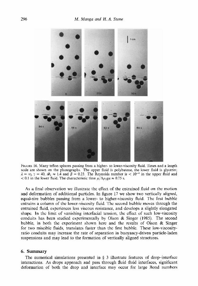
The coagulation or clustering of particles is studied in figure 16. In the experiment a large number of teflon spheres, initially well distributed, are released into the upper fluid. Since the spheres slow down as they pass through the interface they tend to accumulate and cluster in the vicinity of the interface. In the experiment shown in figure 16, clusters of between 1 and 4 spheres pass through and detach from the interface entraining significant amounts of the upper fluid. The clusters entrain more fluid than the equivalent number of single spheres (compare figures 15 and 16 with figure 13).
296 M. Manga and H . A. Stone
FIGURE 16. Many teflon spheres passing from a higher- to lower-viscosity fluid. Times and a length scale are shown on the photographs. The upper fluid is polybutene, the lower fluid is glycerin; 1 = co, y = 40, BAZ = 1.4 and in the upper fluid and < 0.1 in the lower fluid. The characteristic time p/Apzga = 0.75 s.
= 0.23. The Reynolds number is <
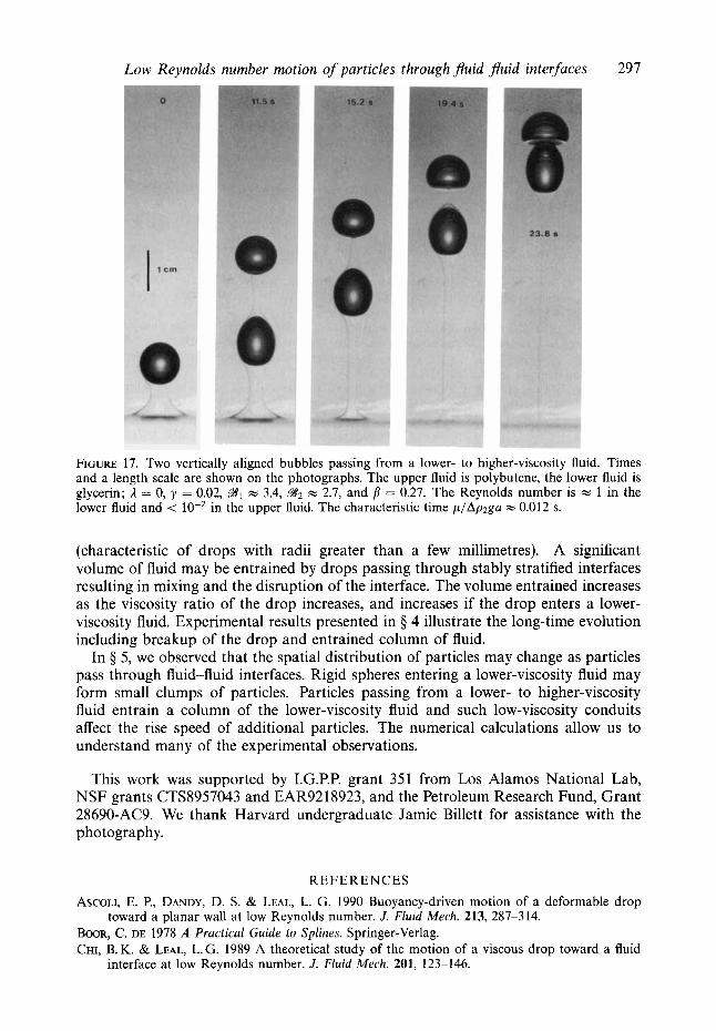
As a final observation we illustrate the effect of the entrained fluid on the motion and deformation of additional particles. In figure 17 we show two vertically aligned, equal-size bubbles passing from a lower- to higher-viscosity fluid. The first bubble entrains a column of the lower-viscosity fluid. The second bubble moves through the entrained fluid, experiences less viscous resistance, and develops a slightly elongated shape. In the limit of vanishing interfacial tension, the effect of such low-viscosity conduits has been studied experimentally by Olson & Singer (1985). The second bubble, in both the experiment shown here and the results of Olson & Singer for two miscible fluids, translates faster than the first bubble. These low-viscosity- ratio conduits may increase the rate of separation in buoyancy-driven particle-laden suspensions and may lead to the formation of vertically aligned structures.
6. Summary The numerical simulations presented in 9 3 illustrate features of dropinterface
interactions. As drops approach and pass through fluid-fluid interfaces, significant deformation of both the drop and interface may occur for large Bond numbers
Low Reynolds number motion of particles through fluid-fluid interfaces 297
FIGURE 17. Two vertically aligned bubbles passing from a lower- to higher-viscosity fluid. Times and a length scale are shown on the photographs. The upper fluid is polybutene, the lower fluid is glycerin; i = 0, y = 0.02, gl = 3.4, = 0.27. The Reynolds number is w 1 in the lower fluid and < lo-’ in the upper fluid. The characteristic time p/Ap2ga w 0.012 s.
= 2.7, and
(characteristic of drops with radii greater than a few millimetres). A significant volume of fluid may be entrained by drops passing through stably stratified interfaces resulting in mixing and the disruption of the interface. The volume entrained increases as the viscosity ratio of the drop increases, and increases if the drop enters a lower- viscosity fluid. Experimental results presented in $ 4 illustrate the long-time evolution including breakup of the drop and entrained column of fluid.
In $ 5, we observed that the spatial distribution of particles may change as particles pass through fluid-fluid interfaces. Rigid spheres entering a lower-viscosity fluid may form small clumps of particles. Particles passing from a lower- to higher-viscosity fluid entrain a column of the lower-viscosity fluid and such low-viscosity conduits affect the rise speed of additional particles. The numerical calculations allow us to understand many of the experimental observations.
This work was supported by I.G.P.P. grant 351 from Los Alamos National Lab, NSF grants CTS8957043 and EAR9218923, and the Petroleum Research Fund, Grant 28690-AC9. We thank Harvard undergraduate Jamie Billett for assistance with the photography.
REFERENCES
ASCOLI, E. P., DANDY, D. S. & LEAL, L. G. 1990 Buoyancy-driven motion of a deformable drop
BOOR, C. DE 1978 A Practical Guide to Splines. Springer-Verlag. CHI, B. K. & LEAL, L. G. 1989 A theoretical study of the motion of a viscous drop toward a fluid
toward a planar wall at low Reynolds number. J . Fluid Mech. 213, 287-314.
FORDHAM, S. 1948 On the calculation of surface tension from measurements of pendant drops. Proc. R. SOC. Lond. A 194, 1-16.
GELLER, A. S., LEE, S . H. & LEAL, L. G. 1986 The creeping motion of a spherical particle normal to a deformable interface. J. Fluid Mech. 169, 27-69.
KOCH, D. M. & KOCH, D. L. 1995 Numerical and theoretical solutions for a drop spreading below a free fluid surface. J. Fluid Mech. 287, 251-278.
KOH, C. J. & LEAL, L. G. 1989 The stability of drop shapes for translation at zero Reynolds number through a quiescent fluid. Phys. Fluids A 1, 1309-1313.
KOH, C. J. & LEAL, L. G. 1990 An experimental investigation on the stability of viscous drops translating through a quiescent fluid. Phys. Fluids A 2, 2103-2109.
KOJIMA, M., HINCH, E. J. & ACRIVOS, A. 1984 The formation and expansion of a toroidal drop moving in a viscous fluid. Phys. Fluids 27, 19-32.
LEE, S. H. & LEAL, L. G. 1982 The motion of a sphere in the presence of a deformable interface. 11. A numerical study of the translation of a sphere normal to an interface. J . Colloid Interface Sci. 87, 81-106.
MANGA, M. 1994 The motion of deformable drops and bubbles at low Reynolds numbers: Appli- cations to selected problems in geology and geophysics. PhD thesis, Harvard University.
MANGA, M. & STONE, H. A. 1993 Buoyancy-driven interactions between deformable drops at low Reynolds numbers. J. Fluid Mech. 256, 647-683.
MANGA, M., STONE, H. A. & ~'CONNELL, R. J. 1993 The interaction of plume heads with composi- tional discontinuities in the Earth's mantle. J . Geophys. Res. 98, 19979-19990.
OLSON, P. & SINGER, H. 1985 Creeping plumes. J . Fluid Mech. 158, 511-531. POZRIKIDIS, C. 1990a The instability of a moving viscous drop. J. Fluid Mech. 210, 1-21. POZRIKIDIS, C. 1990b The deformation of a liquid drop moving normal to a plane wall. J. Fluid
Mech. 215, 331-363. RALLISON, J. M. 1984 The deformation of small viscous drops and bubbles in shear flows. Ann. Rev.
Fluid Mech. 16, 45-66. SHI, X. D., BRENNER, M. P. & NAGEL, S . R. 1994 A cascade of structure in a drop falling from a
faucet. Science 265, 219-222. SHOPOV, P. J. & MINEV, P. D. 1992 The unsteady motion of a bubble or drop towards a liquid-liquid
interface. J . Fluid Mech. 235, 123-141. TANZOSH, J., MANGA, M. & STONE, H. A. 1992 Boundary element methods for viscous free-
surface flow problems : Deformation of single and multiple fluid-fluid interfaces. In Boundary Element Technolgies (ed. C. A. Brebbia, & M. S. Ingber), pp. 19-30. Computational Mechanics Publications and Elsevier Applied Science, Southampton.
TJAHJADI, M., STONE, H. A. & OTTINO, J. M. 1994 Estimating interfacial tension via relaxation of drop shapes and filament breakup. AIChE J . 40, 385-394.
YIANTSIOS, S. G. & DAVIS, R. H. 1990 On the buoyancy-driven motion of a drop towards a rigid or deformable interface. J. Fluid Mech. 217. 547-573.