128
Low voltage motors Motor guide Motor guide | February 2014

Low voltage motorsMotor guide
Motor guide | February 2014

2 9AKK105734 EN 02-2014 | ABB Motors and Generators
We provide motors and generators, services and expertise to save energy and improve customers’ processes over the total lifecycle or our products, and beyond.

ABB Motors and Generators | 9AKK105734 EN 02-2014 3
Motor guide – basic technicalinformation about low voltage standard
motors
Motors and Generators
© Copyright 2014 ABB. All rights reserved. Speci ications subject to change without
notice. ISBN 952-91-0728-5
Third edition 2014

4 9AKK105285 EN 02-2014 | ABB Motors and Generators
Motor guideContents
8 1. Introduction9 1.1 About ABB
10 1.2 IEC low voltage motor ranges10 1.2.1 Standard induction motors10 1.2.2 Motors for explosive atmospheres11 1.2.3 Frequency-controlled motors13 1.3 Complete product offering
16 2. Energy saving and the environment17 2.1 Energy efficiency standards17 2.1.1 IEC efficiency classes18 2.1.2 Energy efficiency schemes19 2.1.3 Efficiency testing standards20 2.2 Life cycle approach and energy appraisal20 2.2.1 Energy appraisal21 2.3 Environmental management within ABB21 2.3.1 ISO 1400121 2.3.2 Hazardous substances21 2.3.3 Materials selection
24 3. Standards 25 3.1 Definitions
26 3.2 Standards tables26 3.2.1 The main standards for low voltage motors 27 3.2.2 The main EU directives for motors27 3.2.3 Efficiency determination for motors outside Europe28 3.3 Direction of rotation
29 3.4 Cooling31 3.5 Degrees of protection: IP code/IK code32 3.6 Standard voltage ranges33 3.7 Voltage and frequency
34 3.8 Tolerance35 3.9 Mounting arrangements
36 3.10 Dimensions38 3.11 Output power and frame size ratio
ABB Motors and Generators | 9AKK105285 EN 02-2014 5
42 4. Electrical design – induction motors43 4.1 Induction motor
44 4.2 Insulation 45 4.3 Thermistors
45 4.4 Ambient temperatures and high altitudes46 4.5 Starting methods46 4.5.1 Direct-on-line (DOL) starting46 4.5.2 Star-delta starting47 4.5.3 Soft starters48 4.5.4 Starting with a variable speed drive49 4.6 Starting limitations56 4.7 Duty types
60 4.8 Uprating61 4.9 Efficiency and types of losses62 4.10 Power factor65 4.11 Air flow and air speed66 4.12 Connection diagram
68 5. Mechanical design69 5.1 Motor construction70 5.2 Frame constructions71 5.3 Terminal boxes73 5.4 Bearings74 5.5 Drain holes and humidity75 5.6 External radial and axial forces of the motor
75 5.7 Balancing 76 5.8 Vibration
77 5.9 Surface treatment
80 6. Noise81 6.1 Sound pressure level and sound power level82 6.2 Weighting filters83 6.3 Octave bands84 6.4 Additional sound sources85 6.5 Noise components of a motor87 6.6 Airborne and structure-borne noise88 6.7 Sound pressure levels
90 7. Installation and maintenance91 7.1 Delivery acceptance91 7.2 Insulation resistance check92 7.3 Torque on terminals

6 9AKK105285 EN 02-2014 | ABB Motors and Generators
92 7.4 Operation93 7.5 Handling94 7.6 Foundations95 7.7 Coupling alignment96 7.7.1 Mounting pulleys and coupling halves97 7.8 Slide rails98 7.9 Mounting bearings98 7.10 Lubrication99 7.11 Fuse rating
100 8. The SI system 101 8.1 Quantities and units 102 8.2 Prefixes 103 8.3 Conversion factors
108 9. Ordering 109 9.1 Selecting a motor 111 9.2 Online tools 111 9.2.1 Optimizer 112 9.2.2 DriveSize and MotSize 112 9.3 Loading (kW) 113 9.4 Speed 113 9.5 Starting the motor 114 9.6 Operating environment 114 9.7 Ordering and order check list
116 10. Variable speed drives 117 10.1 Types of drives 118 10.2 Pulse Width Modulation 118 10.3 Dimensioning the drive 120 10.4 Loadability (torque) 121 10.4.1 Improving loadability 122 10.5 Insulation level 122 10.6 Earthing 123 10.7 Operating at maximum speed 124 10.8 Balancing 124 10.9 Critical speeds 124 10.10 Shaft seals 126 10.11 Low speed operation

ABB Motors and Generators | 9AKK105285 EN 02-2014 7
1. Introduction
1. Introduction 81.1 About ABB 91.2 IEC low voltage motor ranges 101.2.1 Standard induction motors 101.2.2 Motors for explosive atmospheres 101.2.3 Frequency-controlled motors 111.3 Complete product offering 13

8 9AKK105285 EN 02-2014 | ABB Motors and Generators
IntroductionThis guide provides basic information about IEC low voltage motors. In this context, low voltage refers to motors that operate at voltages less than 1 000 V and produce a maximum power of 1 000 kW. The reference values provided in this guide apply specifically to ABB’s Process performance motor range.
The designation IEC means that the motors conform to standards developed by the International Electrotechnical Commission. For example, IEC standardizes the frame size of motors; in the case of Process performance motors, there are frame sizes starting from IEC frame 56 in the aluminum range up to 450 (millimeters from shaft to base) in the cast iron motor range. More recently, IEC standards have specified how motors should be classified into energy efficiency classes.

ABB Motors and Generators | 9AKK105285 EN 02-2014 9
Introduction1.1 About ABBABB (www.abb.com) is a leader in power and automation technologies that enable utility and industry customers to improve their performance while lowering environmental impact. The ABB Group of companies operates in around 100 countries and employs about 145,000 people. ABB manages its business based on a divisional structure, with five divisions: Power Products, Power Systems, Discrete Automation and Motion, Low Voltage Products and Process Automation.
At ABB, motors are manufactured and marketed by the business unit Motors and Generators, which is part of ABB’s Discrete Automation and Motion division. The Discrete Automation and Motion division offers a wide range of products and services including drives, motors, generators, power electronics systems, rectifiers, power quality and power protection products, converters, photovoltaic inverters, programmable logic controllers (PLCs), and robots. These products help customers to improve productivity, save energy, improve quality and generate energy.
The business unit Motors and Generators manufactures low, medium and high voltage motors and generators, and mechanical power transmission products. ABB products are backed up by an extensive portfolio of services and a high level expertise in a wide variety of motor applications.

10 9AKK105285 EN 02-2014 | ABB Motors and Generators
1.2 IEC low voltage motor rangesIn this overview, motors are classified primarily according to their fundamental physical differences, and secondarily, according to their purpose of use. Accordingly, we divide motors into two ranges of induction motors, four types of motors for explosive atmospheres, frequency controlled motors, most notable of which are synchronous motors, and special application motors. The last category of motors include, for example, marine motors, brake motors, and smoke extraction motors, which are based on the basic induction motor but have modifications that vary according to the purpose of use. Their features are not further described here.
1.2.1 Standard induction motorsABB offers two types of low voltage induction motor series: Process performance and General performance motors. The first are the most commonly chosen induction motors for demanding industrial uses and cover frame sizes 63 – 450, or 0.12 – 1 000 kW. Furthermore, these motors exist in three energy efficiency classes: IE2, IE3, and IE4.
General performance motors form the basic motor series in the IE2 efficiency class, with less optional features than for Process performance motors, but available off-the-shelf worldwide. These motors come in frame sizes 56 – 355, corresponding to 0.06 – 355 kW.
Both series include cast iron and aluminum subranges.
1.2.2 Motors for explosive atmospheresABB’s motors for explosive atmospheres, or so called Ex-motors, comply fully with the ATEX directive 94/9/EC, which sets forth the mandatory duties and responsibilities of the manufacturer of products installed in the European Economic area. In addition to ATEX certification, the global IECEx certificate is available for most ABB Ex-products. National certificates like CQST for China, CU-TR required by the customs union of Russia, Belarus and Kazakhstan, or other, can also be ordered for a wide selection of products. Please refer to the product catalog and variant code section for availability of different certificates.
Equipment for explosive atmospheres is grouped according to the location above or underground and type of explosive atmosphere (gas/dust) it is intended for. Equipment protection levels (EPLs) designate the likelihood of the equipment becoming a source of ignition and distinguish between an explosive gas atmosphere, a dust atmosphere, and the explosive atmospheres in mines susceptible to fire damp. Further, explosive atmospheres are divided into zones according to the

ABB Motors and Generators | 9AKK105285 EN 02-2014 11
risk posed by explosive gas (G) or dust (D). The table below shows the correlation between equipment groups, EPLs, zones, and protection types used in motors. In addition, the required temperature class of the equipment must be taken in consideration; it depends on the ignition temperature of the flammable gas or dust present in the environment, as well as the subgroup of the gas or dust.
Motors for explosive atmospheres are available from frame size 71 to 450 (80 to 450 in flame proof design) or from 0.25 kW up to 1000 kW.
Standard
IEC 60079-0
EN 60079-0
Installation
Zone acc. to
IEC 60079-10-x
EN 60079-10-x
ATEX Directive
94/9/EC
Main motor
protection types
Group EPL
Protection
level Zones
Equipment
group
Equipment
category
I Ma very high NA I M1 NA
(Mines) Mb high (Mines) M2
II(Gas)
Ga very high 0
II
(Surface)
1G NA
Gb high 1 2G Ex d/Ex de Ex p, Ex e
Gc enhanced 2 3G Ex nA
III(Dust)
Da very high 20 1D NA
Db high 21 2D Ex tb IP 65
Dc enhanced 22 3D Ex tc IP 65/IP 55
1.2.3 Frequency controlled motorsFrequency controlled motors refer to motor series that are invariably used together with a frequency converter. This category of motors includes two types of synchronous motors, namely synchronous reluctance motors and permanent magnet motors, as well as roller table motors, high speed motors, and servomotors.
ABB provides two synchronous reluctance motor series: High-output and IE4 synchronous reluctance motors. The High output motors are best suited for applications requiring a high power to size ratio and extend from frame size 90 to 315, or 1.1 to 350 kW, with a minimum efficiency level of IE2. As the name suggests, IE4 synchronous reluctance motors provide the highest efficiency available and range from frame size 160 to 315, corresponding to 7.5 to 315 kW.
Permanent magnet motors are suited for applications requiring high torque density and operating at a maximum speed of 600 r/min at 400 V. Permanent magnet motors are provided either with self-cooling or with separate cooling. Frame sizes in the low voltage area range from 280 to 450 and a maximum of 1000 kW (with a 690 V voltage).

12 9AKK105285 EN 02-2014 | ABB Motors and Generators
The high speed range covers standard motors in the 3600 – 5100 rpm speed area. In addition, custom motors for specific applications have been made all the way up to 60 000 rpm.
Low voltage servomotors include two series of High dynamic power (HDP) motors: IP54 and IP23. These motors provide an extremely good power to size ratio through low moment of inertia and high pulse torque and are best suited for rough conditions where high overloads may occur. The motors range from frame size 100 to 250, or 2 to 750 kW.
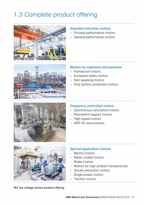
ABB Motors and Generators | 9AKK105285 EN 02-2014 13
IEC low voltage motors product offering
1.3 Complete product offering
Standard induction motors − Process performance motors − General performance motors
Motors for explosive atmospheres − Flameproof motors − Increased safety motors − Non-sparking motors − Dust ignition protection motors
Frequency controlled motors − Synchronous reluctance motors − Permanent magnet motors − High speed motors − HDP AC servomotors
Special application motors − Marine motors − Water cooled motors − Brake motors − Motors for high ambient temperatures − Smoke extraction motors − Single phase motors − Traction motors

14 9AKK105285 EN 02-2014 | ABB Motors and Generators

ABB Motors and Generators | 9AKK105285 EN 02-2014 15
2. Energy saving and the environment 162.1 Energy efficiency standards 172.1.1 IEC efficiency classes 172.1.2 Energy efficiency schemes 182.1.3 Efficiency testing standards 192.2 Life cycle approach and energy
appraisal20
2.2.1 Energy appraisal 202.3 Environmental management
within ABB21
2.3.1 ISO 14001 212.3.2 Hazardous substances 212.3.3 Materials selection 21
2. Energy saving and the environment

16 9AKK105285 EN 02-2014 | ABB Motors and Generators
Energy saving and the environmentThe world industry and commerce are facing an energy challenge. Global demand for energy is rising steadily. At the same time, pressures to reduce energy consumption, to lower carbon dioxide (CO2) emissions and provide secure power supplies are becoming ever stronger.
Efficient motors help cut energy costs and limit carbon dioxide emissions. It has been estimated that electric motors account for about 65 per cent of the electricity consumed in industrial applications, so the energy-saving potential among industries is enormous. Energy consumption is dependent on the kW rating of the motor, loading, and the hours run. High-efficiency motors as such can play a significant part in reducing CO2 emissions.
ABB is a long-standing advocate of the need for high efficiency in motors and its policy is to offer high-efficiency motors as standard, available directly from stock. Rather than concentrating solely on efficiency, however, we take a lifecycle approach and seek to minimize the costs associated with our products over their entire lifetime.

ABB Motors and Generators | 9AKK105285 EN 02-2014 17
2.1 Energy efficiency standardsThe International Electrotechnical Commission (IEC) has introduced standards relating to energy efficient motors. IEC 60034-2-1 specifies rules concerning efficiency testing methods and IEC 60034-30 defines efficiency classes for a wide range of electric motors connected direct on line. IEC 60034-30-1 (which becomes valid in 2014) takes a step further in widening the scope of motors subject to efficiency classes and introduces the IE4 class. VSD-driven motors are out of the scope of this standard and will be dealt with in a standard of its own.
2.1.1 IEC efficiency classes IEC 60034-30-1 defines four IE (International Efficiency) classes for all electric motors that are rated for sinusoidal voltage.
Standard efficiency IE1High efficiency IE2Premium efficiency IE3Super premium efficiency IE4
The scope of this standard is wider than that of IEC 60034-30. IEC 60034-30-1 covers not only standard motors up to eight poles but marine motors, brake motors and motors for explosive atmospheres. Excluded are, among a few other exceptions, power-drive systems and motors completely integrated to an application or frequency converter, so that they cannot be tested independently.
The efficiency levels defined in IEC 60034-30-1 are based on test methods specified in IEC 60034-2-1: 2007 with low uncertainty for IE2 and IE3. The methods in IEC 60034-2-1 determine efficiency values more accurately than the methods previously used. The lowest efficiency value and the associated IE classification are shown on the motor’s rating plate (when applicable).
The following figure shows the correlation between required efficiency and output for the four efficiency classes.
Energy saving and the environment

18 9AKK105285 EN 02-2014 | ABB Motors and Generators
Figure 2.1 IE efficiency classes for 4-pole motors at 50 Hz
2.1.2 Energy efficiency schemesThough the IEC efficiency standards are internationally relevant, differencies in implementation still exist. The following table shows the correlation between the IE efficiency classes and regional efficiency schemes in different parts of the world. Notice that IE1, ‘standard efficiency’, has become substandard in all the regions mentioned, and there are no imperative timelines yet for establishing IE4 regionally.
100
90
80
70
60
50
Output kW
IE4
IE3
IE2
IE1Effi
cien
cy %
160 40015 37 901.5 3 7.50.12 0.37 0.75 1000

ABB Motors and Generators | 9AKK105285 EN 02-2014 19
IEC 60034-30-1 IE2 - high efficiency IE3 - premium efficiency
Australian MEPS Required level Adoption as standard under discussion
Brazilian Labeling
Program, PBE
Required level; scope of motors was
extended in Dec. 2012
-
Canada Energy
Efficiency Act
Required level for 201-500 HP foot-
mounted and all 1-500 HP footless
and 8-pole motors
Required level for 1-200 HP foot-
mounted motors
China Energy Label Required level -
EU MEPS ‘IE2 high efficiency’, required level ‘IE3 premium efficiency’, required by
2015 for 7.5 - 375 kW motors
Korean MEPS Required level for 2-8 pole motors Required for 2-8 pole motors by 2017
Mexican MEPS Required level identical to IE2 Expected to follow EISA IE3 in
the future
USA, EISA2007 ‘Energy efficient’, required level for
201-500 HP 2-6 pole and 1-500 HP
8-pole motors
NEMA
premium efficiency required for 1-200
HP, 2-6 pole motors
Table 2.1 Correlation between IEC and regional efficiency schemes
The IEC60034-30-1 only defines the requirements for efficiency classes and aims to create a basis for international consistency. It does not specify which motors must be supplied with which efficiency level. This is left to the respective regional legislation. Within the European Union, Motor Regulation EC 640/2009 is the default legislative requirement and sets the minimum efficiency levels for placing motors on the market or commissioning them.
2.1.3 Efficiency testing standards In addition to IEC 60034-2-1 (EU), there are two other major testing standards, namely IEEE 112-2004 (USA), and CSA 390-10 (Canada). The main difference is that IEEE 112 determines total motor losses with a direct method and therefore gives the lowest efficiency values.
In addition, the Brazilian standard NBR 17094-1 deviates in the way the motor’s reference temperature is determined. NBR uses frame temperature, whereas other standards use winding temperature as the reference temperature.
IEC 60034-2: 1996 (the old IEC method) specifies the indirect method for defining motor efficiency. With this method, additional losses are assumed at 0.5 per cent of the motor’s input power, which is lower than real losses for small motors and therefore gives higher efficiency values than the current method.

20 9AKK105285 EN 02-2014 | ABB Motors and Generators
2.2 Life cycle approach and energy appraisalTo achieve the best return on investment, users of production equipment need to apply a life cycle approach when considering investing in major equipment. The lifecycle cost (LCC) is the total cost for purchasing, installing, operating, maintaining and disposing of an item of machinery.
It is necessary to raise awareness of the financial benefits of energy efficiency. Payback times of an item of machinery can be extremely short but many businesses still focus on the purchase price when buying new equipment, instead of considering running costs over the lifespan.
The purchase price of an electric motor and drive, for instance, is just 1-3 per cent of what the owner will spend on energy to run the equipment over its lifetime. The significance of a variable speed drive in efficiency considerations is in its quality to control the speed of the motor and therefore ensure that it runs no faster than actually needed.
LCC should be calculated not only on new installations but also existing ones. Existing systems provide much greater scope for efficiency improvements than new installations. The volume of systems in use exceeds the volume of annual new installations many times over. Additionally, many existing installations can offer considerable scope for improvement if the duty has changed since the system was first installed.
2.2.1 Energy appraisal ABB has devised a simple and methodical energy appraisal process that presents the energy saving potential of selected applications to the end users. The starting point for an energy appraisal is to indentify applications where energy can be saved immediately.
Energy appraisals are most suitable for processes with variable torque applications that obey the cube law, run continuously, and where the flow is controlled by a mechanical means such as valves or dampers. This is where the savings from installing a variable speed drive typically are the most significant compared to the initial investment cost.
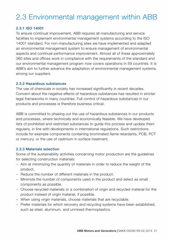
ABB Motors and Generators | 9AKK105285 EN 02-2014 21
2.3 Environmental management within ABB 2.3.1 ISO 14001To ensure continual improvement, ABB requires all manufacturing and service facilities to implement environmental management systems according to the ISO 14001 standard. For non-manufacturing sites we have implemented and adapted an environmental management system to ensure management of environmental aspects and continual performance improvement. Almost all of these approximately 360 sites and offices work in compliance with the requirements of the standard and our environmental management program now covers operations in 59 countries. It is ABB’s aim to further advance the adaptation of environmental management systems among our suppliers.
2.3.2 Hazardous substancesThe use of chemicals in society has increased significantly in recent decades. Concern about the negative effects of hazardous substances has resulted in stricter legal frameworks in many countries. Full control of hazardous substances in our products and processes is therefore business critical.
ABB is committed to phasing out the use of hazardous substances in our products and processes, where technically and economically feasible. We have developed lists of prohibited and restricted substances to guide this process and update them regularly, in line with developments in international regulations. Such restrictions include for example components containing brominated flame retardants, PCB, PCT or mercury, or the use of cadmium in surface treatment.
2.3.3 Materials selectionSome of the sustainability activities concerning motor production are the guidelines for selecting construction materials:
− Aim at minimizing the quantity of materials in order to reduce the weight of the product.
− Reduce the number of different materials in the product. − Minimize the number of components used in the product and select as small
components as possible. − Choose recycled materials or a combination of virgin and recycled material for the
product instead of virgin material, if possible. − When using virgin materials, choose materials that are recyclable. − Prefer materials for which recovery and recycling systems have been established,
such as steel, aluminum, and unmixed thermoplastics.

22 9AKK105285 EN 02-2014 | ABB Motors and Generators

ABB Motors and Generators | 9AKK105285 EN 02-2014 23
3. Standards
3 Standards 243.1 Definitions 253.2 Standards tables 263.2.1 The main standards for
low voltage motors 263.2.2 The main EU directives for motors 273.2.3 Efficiency determination for
motors outside Europe 273.3 Direction of rotation 283.4 Cooling 293.5 Degrees of protection: IP code/IK code 313.6 Standard voltage ranges 323.7 Voltage and frequency 333.8 Tolerance 343.9 Mounting arrangements 353.10 Dimensions 363.11 Output power and frame size ratio 38

24 9AKK105285 EN 02-2014 | ABB Motors and Generators
StandardsABB Motors and Generators build motors and generators to comply with international IEC and CENELEC standards. Within the European Union, ABB takes into account relevant EU-regulations, VDE-regulations, and DIN-standards. Motors conforming to other national and international specifications are also available.
All ABB motor production units are ISO 14001 certified and conform to applicable EU directives.
ABB strongly supports the drive to harmonize international standards and actively contributes to various technical committees and working groups within IEC, CENELEC and IECEx system.

ABB Motors and Generators | 9AKK105285 EN 02-2014 25
Standards3.1 DefinitionsDirective A legislative act of the European Union to achieve a particular result in the EU member states.
StandardA specifications document established as a result of consensus between international technical experts working for a standards organization such as the International Electrotechnical Commission (IEC), the European Committee for Electrotechnical Standardization (CENELEC), or a national standards organization (NEMA in the US, DKE in Germany).
Adoption of IEC standards by any country or manufacturer is entirely voluntary.
Harmonized standardA standard that provides conformity with corresponding requirements of an EU directive to demonstrate compliance with EU legislation.
Harmonized standards are published in the Official Journal (OJ) of the European Union and their application is mandatory to the extent that a corresponding directive requires.

26 9AKK105285 EN 02-2014 | ABB Motors and Generators
3.2 Standards tablesThe following tables serve as reference lists for electrical and mechanical standars that apply to most induction motors depending on motor type and type of protection.
3.2.1 The main standards for low voltage motors
Electrical Title
IEC / EN 60034-1 Rating and performance
IEC / EN 60034-2-1 Standard methods for determining losses and efficiency from tests (excluding machines for traction vehicles)
IEC / EN 60034-2-2 Specific methods for determining separate losses of large machinesfrom tests – Supplement to IEC 60034-2-1
IEC / EN 60034-8 Terminal markings and direction of rotation
IEC / EN 60034-11 Thermal protection
IEC / EN 60034-12 Starting performance of single-speed three-phase cage induction motors
IEC / TS 60034-17 Cage induction motors when fed from converters – Application guide
IEC / TS 60034-25 Guidance for the design and performance of AC motors specifically designed for converter supply
IEC / EN 60034-26 Effects of unbalanced voltages on the performance of three-phase cage induction motors
IEC / EN 60034-30 Efficiency classes of single-speed three-phase cage induction motors (IE-Code)
IEC / TS 60034-31 CLC/TS 60034-31
Selection of energy-efficient motors including variable speed applications – Application guide
IEC 60038 IEC standard voltagesIEC 60050-411 International electrotechnical vocabulary – Chapter 411: Rotating machines
Mechanical Title
IEC / EN 60034-5 Degrees of protection provided by the integral design of rotating electrical machines (IP code) - Classification
IEC / EN 60034-6 Methods of cooling (IC code)
IEC / EN 60034-7Classification of types of construction, mounting arrangements and terminal box position (IM Code)
IEC / EN 60034-9 Noise limits
IEC / EN 60034-14 Mechanical vibration of certain machines with shaft heights 56 mm and higher - Measurement, evaluation and limits of vibration severity
IEC / EN 60072-1 Dimensions and output series for rotating electrical machinesPart 1: Frame sizes 56 to 400 and flange numbers 55 to 1080
IEC / EN 60529 Degree of protection provided by enclosure (IP Code)
EN 50102 Degrees of protection provided by enclosures for electrical equipment against external mechanical impacts (IK code)
EN 50347 General purpose three-phase induction motors having standard dimensions and outputs - Frame sizes 56 to 315 and flange numbers 65 to 740

ABB Motors and Generators | 9AKK105285 EN 02-2014 27
Specific applications in addition to the standards above
Smoke extraction motors Title
EN 12101-3 Smoke and heat control systemsSpecification for powered smoke and heat exhaust ventilators
Hazardous areas Title
IEC / EN 60079-0 Equipment - General requirements
IEC / EN 60079-1 Equipment protection by flameproof enclosures “d”
IEC / EN 60079-7 Equipment protection by increased safety “e”
IEC / EN 60079-15 Equipment protection by type of protection “n”
IEC / EN 60079-31 Equipment dust ignition protection by enclosure “t”
IEC / EN 60079-14 Electrical installations design, selection and erection
IEC / EN 60079-17 Electrical installations inspections and maintenance
IEC / EN 60079-19 Equipment repair, overhaul and reclamationIEC / EN 60050-426 International electrotechnical vocabulary- Part 426: Equipment for
explosive atmospheres
IEC / EN 60079-10-1 Classification of areas – Explosive gas atmospheres
IEC / EN 60079-10-2 Classification of areas – Combustible dust atmospheres
3.2.2 The main EU directives for motors
Directive Date Field of application
1994/9/EC ATEX 23 March 1994 Motors used in potentially explosive atmospheres
1999/92/ECWorkers Directive
16 December 1999 Installations, incl. motors, in potentially explosive atmospheres
2006/95/ECLV Directive
12 December 2006 Low voltage motors except for those used in potentially explosive atmospheres
2009/125/ECEcodesign Directive
22 July 2009 Framework for setting ecodesign requirements for energy-related products
2009/640/ECMotor regulation
22 July 2009 Electric motors
Amendment to Motor regulation
Sep/Oct. 2013 Electric motors
3.2.3 Efficiency determination for motors outside Europe
USA IEEE 112-BCSA C390-10
Test procedure for polyphase induction motors and generatorsTest methods, marking requirements, and energy efficiency levels for tree-phase induction motors
Canada CSA C390-10 Test methods, marking requirements, and energy efficiency levels for tree-phase induction motors
China GB/T 1032: 2005 Test methods for induction motors; includes methods identical to IEC 60034-2-1: 2007 with segregated losses
India IS 12615: 2011 Methods identical to IEC 60034-2-1: 2007 (in line with IEC 60034-30: 2008)
Brazil NBR 17094-1: 2008 Three-phase induction motors – Tests
Australia, NewZealand
AS/NZS 1359.102.3 or IEC 60034-2-1AS/NZS 1359.102.1 or IEC 60034-2
Method A for determining losses and efficiency – Three-phase cage induction motors Method B for determining losses and efficiency – Three-phase cage induction motors

28 9AKK105285 EN 02-2014 | ABB Motors and Generators
3.3 Direction of rotationMotor cooling is independent of the direction of rotation, except for certain larger two-pole motors.
When the mains supply is connected to stator terminals marked U, V, and W of a three-phase motor and the mains phase sequence is L1, L2, L3, the motor will rotate clockwise, as viewed from the D-end. The direction of rotation can be reversed by interchanging any two of the three conductors connected to a starter switch or motor.
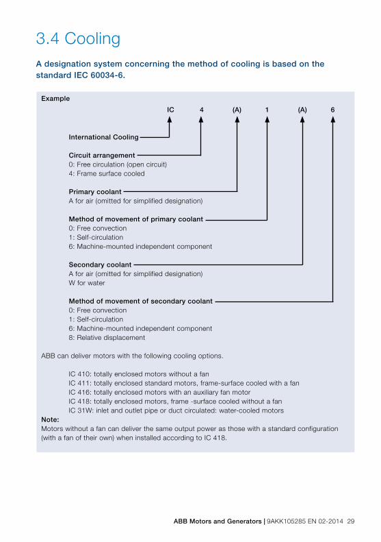
ABB Motors and Generators | 9AKK105285 EN 02-2014 29
3.4 CoolingA designation system concerning the method of cooling is based on the standard IEC 60034-6.
Example
IC 4 (A) 1 (A) 6
International Cooling
Circuit arrangement0: Free circulation (open circuit)4: Frame surface cooled
Primary coolantA for air (omitted for simplified designation)
Method of movement of primary coolant0: Free convection1: Self-circulation 6: Machine-mounted independent component
Secondary coolantA for air (omitted for simplified designation)W for water
Method of movement of secondary coolant0: Free convection1: Self-circulation 6: Machine-mounted independent component8: Relative displacement
ABB can deliver motors with the following cooling options.
IC 410: totally enclosed motors without a fanIC 411: totally enclosed standard motors, frame-surface cooled with a fanIC 416: totally enclosed motors with an auxiliary fan motorIC 418: totally enclosed motors, frame -surface cooled without a fan IC 31W: inlet and outlet pipe or duct circulated: water-cooled motors
Note: Motors without a fan can deliver the same output power as those with a standard configuration (with a fan of their own) when installed according to IC 418.

30 9AKK105285 EN 02-2014 | ABB Motors and Generators
ABB’s motor range
Cooling designation Motor range
IC 410 Typical examples are roller table
motors
IC 411 Standard motors
IC 416 Standard motors (normally bigger
frame sizes only equipped with
auxiliary fan)
IC 418 Fan application motors without a
cooling fan, cooled by the airstream
of the driven machine
IC 31 W Water cooled motors

ABB Motors and Generators | 9AKK105285 EN 02-2014 31
3.5 Degrees of protection: IP code/IK codeClassifications of the degrees of protection provided by enclosures of rotating machines are based on:
− IEC / EN 60034-5 or IEC / EN 60529 for IP code − EN 50102 for IK code
IP protection:Protection of persons against getting in contact with (or approaching) live parts and against contact with moving parts inside the enclosure. Also protection of the machine against the ingress of solid foreign objects. Protection of machines against the harmful effects of the ingress of water.
IP 5 5
Characteristic letter
Degree of protection to persons and to parts of the motors inside the enclosure2: Motors protected against solid objects greater than 12 mm4: Motors protected against solid objects greater than 1 mm5: Dust-protected motors6: Dust-tight motors
Degree of protection provided by the enclosure with respect to harmful effects due to ingress of water3: Motors protected against spraying water4: Motors protected against splashing water5: Motors protected against water jets6: Motors protected against heavy seas
IK code: Classification of degrees of protection provided by enclosure for motors against external mechanical impacts.
Relation between IK code and impact energy
IK code IK 00 IK 01 IK 02 IK 03 IK 04 IK 05 IK 06 IK 07 IK 08 IK 09 IK 10Impact * 0.15 0.2 0.35 0.5 0.7 1 2 5 10 20
Energy ABB
Standard
Joule*not protected according to EN 50102
IK 05
International mechanical protection
Characteristic group
32 9AKK105285 EN 02-2014 | ABB Motors and Generators
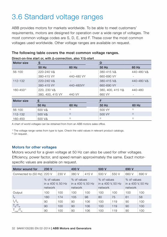
3.6 Standard voltage rangesABB provides motors for markets worldwide. To be able to meet customers’ requirements, motors are designed for operation over a wide range of voltages. The most common voltage codes are S, D, E, and F. These cover the most common voltages used worldwide. Other voltage ranges are available on request.
Motors for other voltagesMotors wound for a given voltage at 50 Hz can also be used for other voltages. Efficiency, power factor, and speed remain approximately the same. Exact motor-specific values are available on request.
Motor wound for 230 V 400 V 500 V 690 V
Connected to (50 Hz) 220 V 230 V 380 V 415 V 500 V 550 V 660 V 690 V
% of valuesin a 400 V, 50 Hz network
% of valuesin a 400 V, 50 Hz network
% of valuesin a 400 V, 50 Hz network
% of values in a 400 V, 50 Hz network
Output 100 100 100 100 100 100 100 100IN 180 174 105 98 80 75 61 58IS/IN 90 100 90 106 100 119 90 100TS/TN 90 100 90 106 100 119 90 100Tmax/TN 90 100 90 106 100 119 90 100
The following table covers the most common voltage ranges.
Direct-on-line start or, with Δ-connection, also Y/Δ-start
Motor size S D
50 Hz 60 Hz 50 Hz 60 Hz
56-100 220-240 VΔ - 380-415 VΔ 440-480 VΔ
380-415 VY 440-480 VY 660-690 VY -
112-132 220-240 VΔ - 380-415 VΔ 440-480 VΔ
380-415 VY 440-480VY 660-690 VY -
160-4501) 220, 230 VΔ 380, 400, 415 YΔ 440-480
380, 400, 415 VY 440 VY 660 VY -
Motor size E F
50 Hz 60 Hz 50 Hz 60 Hz
56-100 500 VΔ 2) 500 VY 2)
112-132 500 VΔ 2) 500 VY 2)
160-450 500 VΔ 2) 2) 2)
A chart of world voltages can be obtained from from an ABB motors sales office.
1) The voltage range varies from type to type. Check the valid values in relevant product catalogs.2) On request.

ABB Motors and Generators | 9AKK105285 EN 02-2014 33
3.7 Voltage and frequency
1
2
3
Y
X1.00 1.02
0.90
0.98
1.10
0.93
0.95
1.05
1.03
0.95
1.09
Figure 3.1 Voltage and frequency deviation in zones A and B.
The impact on temperature rise caused by voltage and frequency fluctuation is defined in IEC 60034-1. The standard divides the combinations into two zones, A and B. Zone A is the combination of voltage deviation of +/-5 % and frequency deviation of +/-2 %. Zone B is the combination of voltage deviation of +/-10 % and frequency deviation of +3/-5 %. This is illustrated in figure 3.1.
Motors are capable of supplying the rated torque in both zones A and B, but the temperature rise will be higher than at rated voltage and frequency. Motors can be run in zone B only for a short period of time.
Key
X axis frequency p.u.Y axis voltage p.u.1 zone A2 zone B (outsice zone A3 rating point

34 9AKK105285 EN 02-2014 | ABB Motors and Generators
3.8 Tolerances
Efficiency Power factor
Lockedrotorcurrent
Lockedrotortorque
Pull-uptorque
Moment of inertia
Noise level
PN (kW) ≤ 150
-15 %(1-η)
-1/6(1-cosϕ)
+20 % of the current
[-15 % +25 %]of the torque
-15 % of the value
± 10 % of the value
+3 dB(A)
PN (kW) > 150
-10 %(1-η)
-1/6(1-cosϕ)
+20 % of the current
[-15 % +25 %]of the torque
-15 % of the value
± 10 % of the value
+3 dB(A)
Slip
PN (kW) < 1 ± 30 %
PN (kW) ≥ 1 ± 20 %
In accordance with IEC 60034-1, tolerance is the maximum allowed deviation between the test result and the declared value on the rating plate (or in the catalog).Test results are based on test procedures in accordance with IEC 60034-2-1, IEC 60034-9, and IEC 60034-12.
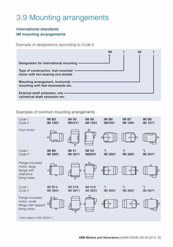
ABB Motors and Generators | 9AKK105285 EN 02-2014 35
3.9 Mounting arrangementsInternational standardsIM mounting arrangements
Example of designations according to Code II
IM 1 00 1
Designation for international mounting
Type of construction, foot-mounted motor with two bearing end shields
Mounting arrangement, horizontalmounting with feet downwards etc.
External shaft extension, onecylindrical shaft extension etc.
Code I IM B3 IM V5 IM V6 IM B6 IM B7 IM B8Code II IM 1001 IM1011 IM 1031 IM1051 IM 1061 IM 1071
Foot-motor
Code I IM B5 IM V1 IM V3 *) *) *)Code II IM 3001 IM 3011 IM3031 IM 3051 IM 3061 IM 3071
Flange-mounted motor, large flange with clearancefixing holes.
Code I IM B14 IM V18 IM V19 *) *) *)Code II IM 3601 IM 3611 IM 3631 IM 3651 IM 3661 IM 3671
Flange-mounted motor, small flange with tapped fixing holes.
*) Not stated in IEC 60034-7
M00
0007
M00
0008
M00
0009
Examples of common mounting arrangements
36 9AKK105285 EN 02-2014 | ABB Motors and Generators
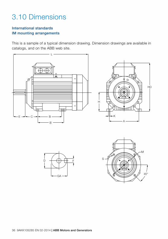
3.10 Dimensions International standardsIM mounting arrangements
This is a sample of a typical dimension drawing. Dimension drawings are available in catalogs, and on the ABB web site.
B
B’
CE
L
GA
FDS
M
45°
H
K
A
HD
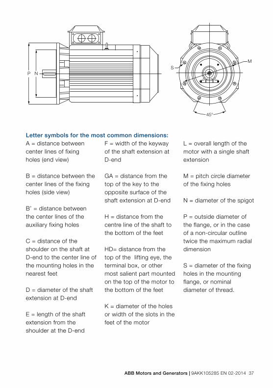
ABB Motors and Generators | 9AKK105285 EN 02-2014 37
Letter symbols for the most common dimensions:A = distance between center lines of fixing holes (end view)
B = distance between the center lines of the fixing holes (side view)
B’ = distance between the center lines of the auxiliary fixing holes
C = distance of the shoulder on the shaft at D-end to the center line of the mounting holes in the nearest feet
D = diameter of the shaft extension at D-end
E = length of the shaft extension from the shoulder at the D-end
F = width of the keyway of the shaft extension at D-end
GA = distance from the top of the key to the opposite surface of the shaft extension at D-end
H = distance from the centre line of the shaft to the bottom of the feet
HD= distance from the top of the lifting eye, the terminal box, or other most salient part mounted on the top of the motor to the bottom of the feet
K = diameter of the holes or width of the slots in the feet of the motor
L = overall length of the motor with a single shaft extension
M = pitch circle diameter of the fixing holes
N = diameter of the spigot
P = outside diameter of the flange, or in the case of a non-circular outline twice the maximum radial dimension
S = diameter of the fixing holes in the mounting flange, or nominal diameter of thread.
SM
45°
NP

38 9AKK105285 EN 02-2014 | ABB Motors and Generators
Standard output
Frame size
Shaft extension diameter
Rated output Flange number
2polesmm
4,6,8polesmm
2poleskW
4poleskW
6poleskW
8poleskW
Freeholes(FF)
Tappedholes(FT)
56 9 9 0.09 or 0.12 0.06 or 0.09 F100 F65
63 11 11 0.18 or 0.25 0.12 or 0.18 F115 F75
71 14 14 0.37 or 0.55 0.25 or 0.37 F130 F85
80 19 19 0.75 or 1.1 0.55 or 0.75 0.37 or 0.55 F165 F100
90S 24 24 1.5 1.1 0.75 0.37 F165 F115
90L 24 24 2.2 1.5 1.1 0.55 F165 F115
100L 28 28 3 2.2 or 3 1.5 0.75 or 1.1 F215 F130
112M 28 28 4 4 2.2 1.5 F215 F130
132S 38 38 5.5 or 7.5 5.5 3 2.2 F265 F165
132M 38 38 - 7.5 4 or 5.5 3 F265 F165
160M 42 42 11 or 15 11 7.5 4 or 5.5 F300 F215
160L 42 42 18.5 15 11 7.5 F300 F215
180M 48 48 22 18.5 - - F300
180L 48 48 - 22 15 11 F300
200L 55 55 30 or 37 30 18.5 or 22 15 F350
225S 55 60 - 37 - 18.5 F400
225M 55 60 45 45 30 22 F400
250M 60 65 55 55 37 30 F500
280S 65 75 75 75 45 37 F500
280M 65 75 90 90 55 45 F500
315S 65 80 110 110 75 55 F600
315M 65 80 132 132 90 75 F600
3.11 Output power and frame size ratioSeveral countries have implemented a minimum energy efficiency performance standard (MEPS) through national legislation. IEC sets guidelines for testing and classification of motors according to standards. The following tables present two applications of power vs. frame size standards, one for Europe and another for Brazil.
In Europe, the CENELEC standard EN 50347 lays down data for rated output and mounting, i.e. shaft height, fixing dimensions and shaft extension dimensions, for various degrees of protection and sizes. It covers totally enclosed fan-cooled squirrel-cage motors at 50 Hz, frame sizes 56 M to 315 M.
Table 3.1 Power - frame size correlation according to CENELEC

ABB Motors and Generators | 9AKK105285 EN 02-2014 39
Power kW Frame HP 2 poles 4 poles 6 poles 8 poles
0.18 0.25 63 63 71 71
0.25 0.33 63 63 71 80
0.37 0.50 63 71 80 90S
0.55 0.75 71 71 80 90L
0.75 1 71 80 90S 90L
1.1 1.5 80 80 90S 100L
1.5 2 80 90S 100L 112M
2.2 3 90S 90L 100L 132S
3.0 4 90L 100L 112M 132M
3.7 5 100L 100L 132S 132M
4.7 6 112M 112M 132S 160M
5.5 7.5 112M 112M 132M 160M
7.5 10 132S 132S 132M 160L
9.2 12.5 132S 132M 160M 180M/L
11.0 15 132M 132M 160M 180L
15.0 20 160M 160M 160L 180L
18.5 25 160M 160L 180L 200L
22 30 160L 180M 200L 225S
30 40 200M 200M 200L 225M
37 50 200L 200L 225M 250S
45 60 225S 225S 250S 250M
55 75 225M 225M 250M 280S
75 100 350M 250M 280S 280M
90 125 280S 280S 280M 315M
110 150 280M 280M 315M 315M
132 175 315S 315S 315M 355
150 200 315S 315S 315M 355
185 250 315S 315M 355 355
220 300 355 355 355 355
260 350 355 355 355 355
300 400 - 355 355 -
330 450 - 355 355 -
370 500 - 355 - -
Table 3.2 Power - frame size correlation according to NBR
Brazil requires that motors imported to Brazil comply with the national NBR standards for low voltage motors. NBR 17094-1:2008 defines the frame-power relation as shown in the table below.

40 9AKK105285 EN 02-2014 | ABB Motors and Generators

ABB Motors and Generators | 9AKK105285 EN 02-2014 41
4. Electrical design – induction motors
4. Electrical design – induction motors 424.1 The induction motor 434.2 Insulation 444.3 Thermistors 454.4 Ambient temperatures and
high altitudes 454.5 Starting methods 464.5.1 Direct-on-line (DOL) starting 464.5.2 Star-delta starting 464.5.3 Soft starters 474.5.4 Starting with a variable speed drive 484.6 Starting limitations 494.7 Duty types 564.8 Uprating 604.9 Efficiency and types of losses 614.10 Power factor 624.11 Air flow and air speed 654.12 Connection diagram 66

42 9AKK105285 EN 02-2014 | ABB Motors and Generators
Electrical design – induction motorsThe electrical and mechanical design chapters of this guide focus on induction motors.
Designing motors that deliver good all-round performance involves a delicate balance between a number of factors which include efficiency, cost, temperature rise, vibration, noise, bearing selection, and slot and fan design. Only the correct balance will result in high quality motors which are efficient and reliable and provide a long service life.

ABB Motors and Generators | 9AKK105285 EN 02-2014 43
Electrical design – induction motors4.1 The induction motorABB’s low voltage induction motors are three-phase electric motors whose rotating power is based on electromagnetic induction. The current led to motor windings creates a rotating magnetic field, which induces a voltage in the rotor bars. The bars form a closed circuit where current begins to circulate, forming another magnetic field. The magnetic fields of the rotor and stator interact in such a way that the rotor starts following the magnetic field of the stator, thus producing torque.
In the nature of asynchronous motors, the rotor tends to fall behind the speed of the magnetic field in the stator. When mechanical load increases on the motor shaft, the difference in speed (slip) increases, and a higher torque is produced.
ABB’s low voltage induction motors cover the power range from 0.06 to 1000 kW.

44 9AKK105285 EN 02-2014 | ABB Motors and Generators
4.2 InsulationABB uses class F insulation, which, with temperature rise class B, is the most commonly required insulation system for industrial motors.
Class F insulation system − Max. ambient temperature 40 °C − Max. permissible temperature rise 105 K − Hotspot temperature margin +10 K
Class B temperature rise − Max. ambient temperature 40 °C − Max. permissible temperature rise 80 K − Hotspot temperature margin +10 K
The use of class F insulation with class B temperature rise gives ABB products a 25 °C safety margin. This can be exploited to increase the loading of the motor for limited periods, to operate at higher ambient temperatures or altitudes or with greater voltage and frequency tolerances. It can also be exploited to extend insulation life. For instance, already a 10 K temperature reduction has a relevant effect on insulation lifetime.
Figure 4.1 Safety margins per insulation class
Hotspot temperature margin
Permissible temperature rise
Maximum ambient temperature
Insulation classMaximum winding temperature
180
155
130120
40
130 155 180B F H
40 40 40
80 105 125
C
10
10
15

ABB Motors and Generators | 9AKK105285 EN 02-2014 45
4.3 ThermistorsThermistors are temperature-dependent resistors inserted inside the winding heads − one for each phase − to control motor temperature. Under a certain temperature, the thermistor shows a fairly constant low resistance, but from a certain temperature upwards this resistance dramatically increases by a factor of 20 and more. The resistance change is transformed into connection signals (warning or disconnection) resulting in thermal machine protection.
4.4 Ambient temperatures and high altitudes Normal motors are designed for operation at a maximum ambient temperature of 40 ºC and at a maximum altitude of 1000 meters above sea level. If a motor is operated at higher ambient temperatures, it should be derated according to the table below. Note that when the output power of a standard motor is derated, the relative values, such as IS/IN, in catalogs will change.
Ambient Temperature, °C 30 40 45 50 55 60 70 80
Permitted output, % of rated output 107 100 96.5 93 90 86.5 79 70
Height above sea level, m 1000 1500 2000 2500 3000 3500 4000
Permitted output, % of rated output 100 96 92 88 84 80 76
Table 4.1 Permitted output in high ambient temperatures or at high altitudes

46 9AKK105285 EN 02-2014 | ABB Motors and Generators
4.5 Starting methodsThe most common motor starting methods are introduced next. They are: direct-on-line and star-delta starting, and starting with a softstarter or variable speed drive.
Connection transientsIt is important to remember that the term ‘starting current’ refers to a steady-state root-mean-square (rms) value. This is the value measured when, after a few cycles, the transient phenomena have died out. The peak value of the transient current may be about 2.5 times the steady-state starting current, but decays rapidly. The starting torque of the motor behaves similarly, and this should be borne in mind if the moment of inertia of the driven machine is high, since the stresses on the shaft and coupling can be great.
4.5.1 Direct-on-line (DOL) startingThe simplest way to start a squirrel cage motor is to connect it directly to the mains supply. In this case, a direct-on-line (DOL) starter is the only starting equipment required. However, the limitation of this method is that it results in a high starting current, often several times the rated current of the motor. Also the starting torque is very high, and may result in high stresses on the couplings and the driven application. Even so, it is the preferred method except when there are special reasons for avoiding it.
4.5.2 Star-delta startingIf it is necessary to restrict the starting current of a motor because of supply limitations, the star-delta (Y/Δ) method can be employed. When a motor wound for 400 V/Δ, for instance, is started with winding Y connected, this method will reduce the starting current to about 30 per cent of the current reached with DOL, and the starting torque will be reduced to about 25 per cent of its DOL value.
However, before using this method, it must be determined whether the reduced motor torque is sufficient to accelerate the load over the motor’s speed range.
Contact your nearest ABB sales office for the MotSize dimensioning tool, or download it from our web site. ABB offers a full range of low voltage products for motor starting and control.

ABB Motors and Generators | 9AKK105285 EN 02-2014 47
A sample taken from the MotSize dimensioning program showing DOL starting curves for a cast iron motor:1. Starting torque at Un
2. Starting torque at 80 % Un
3. Torque loadFigure 4.2 DOL starting
A sample taken from the MotSize dimensioning program showing Y/Δ starting curves for an aluminum motor:1. Starting torque at Un
2. Starting torque at 80 % Un
3. Torque loadFigure 4.3 Star-delta starting
4.5.3 SoftstartersA softstarter limits the starting current of the motor and so provides a smooth start. The magnitude of the starting current is directly dependent on the static torque requirement during a start and on the mass of the load to be accelerated. ABB softstarters have adjustable settings to meet any application requirements. Gradually increasing the motor voltage, and thereby torque, results in a very smooth start. When the motor is well up in speed, it is common to bypass the softstarter to avoid power loss from the semiconductors during continuous operation. To bypass the softstarter it is common to use an externally mounted, AC-1 rated contactor.
A bypass contact can also be built into the softstarter like in ABB’s softstarter ranges PSR, PSE, and PSTB. These softstarters are among the most compact available in the market.
In the ABB softstarter, the main circuit is controlled by semiconductors instead of mechanical contacts. Each phase is provided with two anti-parallel connected thyristors, which allows current to be switched at any point within both positive and negative half-cycles.

48 9AKK105285 EN 02-2014 | ABB Motors and Generators
Current Torque
DoL
Y/∆
Softstart
DoL
Y/∆
Softstart
Lead time is controlled by the firing angle of the thyristor which, in turn, is controlled by a built-in printed circuit board.
Figure 4.4 Impact of softstarters on current and torque
Figure 4.5 ABB softstarters
4.5.4 Starting with a variable speed driveSpeed regulation by a variable speed drive is a great advantage when there is need to adjust speed during continuous run, but it is usually not the optimal solution only for starting and stopping the motor.
With a frequency converter, the rated motor torque is available already at a low speed, and the starting current is low, between 0.5 and 1 times rated motor current, and at maximum 1.5 times nominal current. Another available feature in drives is softstop, which is useful when a smooth stop is equally desirable as a smooth start, for example in operating water pumps or running conveyor belts.

ABB Motors and Generators | 9AKK105285 EN 02-2014 49
4.6 Starting limitationsStarting timeStarting time is a function of load torque, inertia and motor torque. As the starting current is always much higher than the rated current, an excessively long starting period will cause harmful temperature rise in the motor. The high current also causes electromechanical stress on the motor.
Permitted starting timeIn view of temperature rise, the starting time must not exceed the time specified in the table. The figures in the table apply to starting from normal operating temperature. When starting from cold, the figures can be doubled.
Motor size Starting method
Number of poles
2 4 6 856 DOL 25 40 NA NA63 DOL 25 40 NA NA71 DOL 20 20 40 4080 DOL 15 20 40 4090 DOL 10 20 35 40100 DOL 10 15 30 40112 DOL 20 15 25 50
Y/D 60 45 75 150132 DOL 15 10 10 60
Y/D 45 30 30 20160 DOL 15 15 20 20
Y/D 45 45 60 60180 DOL 15 15 20 20
Y/D 45 45 60 60200 DOL 15 15 20 20
Y/D 45 45 60 60225 DOL 15 15 20 20
Y/D 45 45 60 60250 DOL 15 15 20 20
Y/D 45 45 60 60280 DOL 15 18 17 15
Y/D 45 54 51 45315 DOL 15 18 16 12
Y/D 45 54 48 36355 DOL 15 20 18 30
Y/D 45 60 54 90400 DOL 15 20 18 30
Y/D 45 60 54 90450 DOL 15 20 18 30
Y/D 45 60 54 90
Table 4.2 Maximum starting times in seconds for occasional starting, single-speed motors

50 9AKK105285 EN 02-2014 | ABB Motors and Generators
Permitted frequency of starting and reversingWhen a motor is subjected to frequent starting, it cannot be loaded at its rated output because of thermal starting losses in the windings. Calculating the permissible output power can be based on the number of starts per hour, the moment of inertia of the load, and the speed of the load. Mechanical stresses may also impose a limit below that of thermal factors.
Permitted output power P =
PN = rated output of motor in continuous duty
m = x X
X = number of starts per hour
JM = moment of inertia of motor in kgm2
J’L = moment of inertia of load in kgm2, recalculated for the motor shaft, i.e. multiplied by (load speed /motor speed)2. The moment of inertia J (kgm2) equals ¼ GD2 in kpm2.
mo = highest permitted number of starts per hour for motor at no load, as stated in the table at right.
Highest permitted number of reversals per hour at no load mr = m0 /4.
oN m
mP −1
(JM + J’L)________Jm

ABB Motors and Generators | 9AKK105285 EN 02-2014 51
Table 4.3 Highest permitted number of starts/hour at no load, m0
Number of poles
Motor size 2 4 6 8
56 12000 9000 - -
63 A, B 11200 8700 - -
71 A, B 9100 8400 16800 15700
80 A, B 5900 8000 16800 11500
90 L 3500 7000 12200 11500
100 L 2800 - 8400 -
112 M 1700 6000 9900 16000
132 M 1700 2900 4500 6600
160 ML 650 - - 5000
180 ML 400 1100 - -
200 ML 385 - 1900 -
225 SM - 900 - 2350
250 SM 300 900 1250 2350
280 SM, ML 125 375 500 750
315 SM, ML 75 250 375 500
355 SM, ML, LK 50 175 250 350
400 L, LK 50 175 250 350
450 L On request

52 9AKK105285 EN 02-2014 | ABB Motors and Generators
Starting characteristicsCatalogs usually state the maximum starting time as a function of motor size and speed. However, the standard IEC 60034-12 specifies the permitted moment of inertia of the driven machine instead of starting time. For small motors, the thermal stress is greatest in the stator winding, whereas for larger motors it is greatest in the rotor winding.
If the torque curves for the motor and the load are known, the starting time can be calculated with the following equation.
TM - TL = (JM + JL) x
whereTM = motor torque, NmTL = load torque, NmJM = moment of inertia of the motor, kgm2
J L = moment of inertia of the load, kgm2
ω = angular velocity of the motor
In case of gearing TL and JL will be replaced by T’L and J’L respectively.If the starting torque TS and maximum torque Tmax of the motor, together with the nature of the load, are known, the approximate starting time can be calculated with the following equation.
tst = x K1
wheretst = starting time, sTacc = acceleration torque, NmK1 = speed constant (2ϕ p
f ) where p represents the number of pole pairs
Speedconstant
Poles FrequencyHz2 4 6 8 10
nm
K1
3000
314
1500
157
1000
104
750
78
600
62 50nm
K1
3600
377
1800
188
1200
125
900
94
720
75 60
Table 4.4 Speed constant K1 as a function of frequency and pole pairs.
dtdω
(JM + J’L)________Tacc
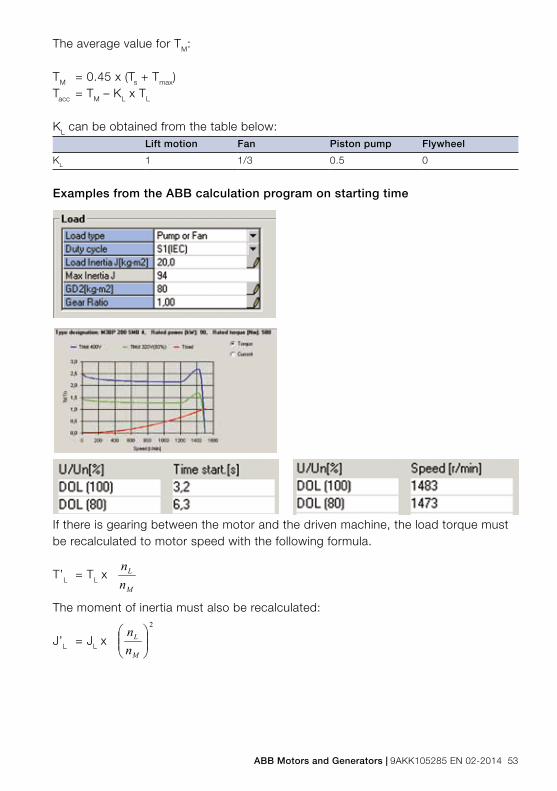
ABB Motors and Generators | 9AKK105285 EN 02-2014 53
The average value for TM:
TM = 0.45 x (Ts + Tmax)Tacc = TM – KL x TL
KL can be obtained from the table below:Lift motion Fan Piston pump Flywheel
KL 1 1/3 0.5 0
Examples from the ABB calculation program on starting time
If there is gearing between the motor and the driven machine, the load torque must be recalculated to motor speed with the following formula.
T’L = TL x
The moment of inertia must also be recalculated:
J’L = JL x
M
L
nn
2
M
L
nn

54 9AKK105285 EN 02-2014 | ABB Motors and Generators
Examples of starting performance with various load torques4-pole motor, 160 kW, 1475 r/min
Torque of the motorTN = 1040 NmTs = 1.7 x 1040 = 1768 NmTmax = 2.8 x 1040 = 2912 NmMoment of inertia of motor: JM = 2.5 kgm2
The load is geared down in a ratio of 1:2
Torque of the loadTL = 1600 Nm at nL = nM/2 r/min T’L = 1600 x 1/2 = 800 Nm at nM r/min
Moment of inertia of the loadJL = 80 kgm2 at nL = nM/2 r/min J’L = 80 x (1/2)2 = 20 kgm2 at nM r/min
Total moment of inertiaJM + J’L at nM r/min2.5 + 20 = 22.5 kgm2
Example 1:TL = 1600 Nm T’L = 800 NmConstant during accelerationTacc = 0.45 x (TS + Tmax) - T’L
Tacc = 0.45 x (1768 + 2912) - 800 = 1306 Nm
tst = x K1
tst = = 2.7 s
(JM + J’L)________Tacc
22.5 x 157__________1306
Lift motion
Torque
T'L
Speed
Fan
Torque
T'L
Speed
Flywheel
Torque
Speed
Piston pump
Torque
T'L
Speed
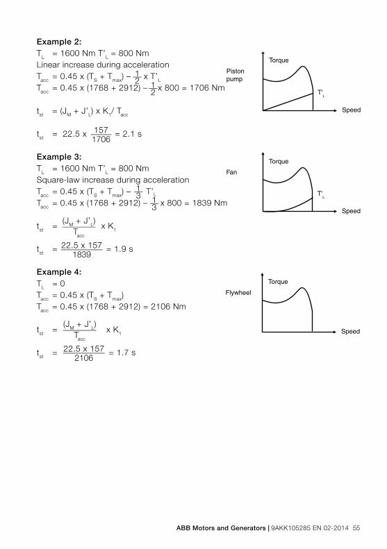
ABB Motors and Generators | 9AKK105285 EN 02-2014 55
Example 2:TL = 1600 Nm T’L = 800 NmLinear increase during accelerationTacc = 0.45 x (TS + Tmax) – x T’L
Tacc = 0.45 x (1768 + 2912) – x 800 = 1706 Nm
tst = (JM + J’L) x K1/ Tacc
tst = 22.5 x = 2.1 s
Example 3:TL = 1600 Nm T’L = 800 NmSquare-law increase during accelerationTacc = 0.45 x (TS + Tmax) – T’L
Tacc = 0.45 x (1768 + 2912) – x 800 = 1839 Nm
tst = x K1
tst = = 1.9 s
Example 4:TL = 0Tacc = 0.45 x (TS + Tmax)Tacc = 0.45 x (1768 + 2912) = 2106 Nm
tst = x K1
tst = = 1.7 s
Lift motion
Torque
T'L
Speed
Fan
Torque
T'L
Speed
Flywheel
Torque
Speed
Piston pump
Torque
T'L
Speed
Lift motion
Torque
T'L
Speed
Fan
Torque
T'L
Speed
Flywheel
Torque
Speed
Piston pump
Torque
T'L
Speed
1__2 1__
2
(JM + J’L)________Tacc
22.5 x 157__________2106
1__3 1__
3
(JM + J’L)________Tacc
22.5 x 157__________1839
Lift motion
Torque
T'L
Speed
Fan
Torque
T'L
Speed
Flywheel
Torque
Speed
Piston pump
Torque
T'L
Speed
157_____1706
56 9AKK105285 EN 02-2014 | ABB Motors and Generators
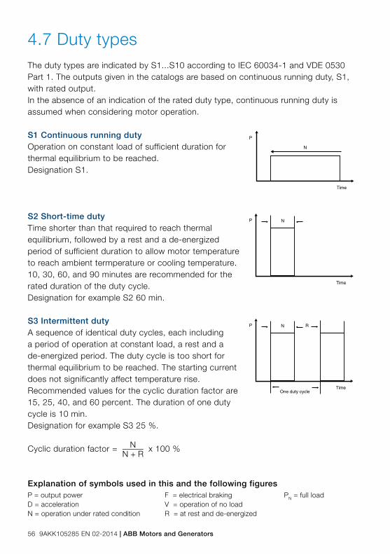
4.7 Duty typesThe duty types are indicated by S1...S10 according to IEC 60034-1 and VDE 0530 Part 1. The outputs given in the catalogs are based on continuous running duty, S1, with rated output.In the absence of an indication of the rated duty type, continuous running duty is assumed when considering motor operation.
S1 Continuous running dutyOperation on constant load of sufficient duration for thermal equilibrium to be reached. Designation S1.
S2 Short-time dutyTime shorter than that required to reach thermal equilibrium, followed by a rest and a de-energized period of sufficient duration to allow motor temperature to reach ambient termperature or cooling temperature. 10, 30, 60, and 90 minutes are recommended for the rated duration of the duty cycle. Designation for example S2 60 min.
S3 Intermittent dutyA sequence of identical duty cycles, each including a period of operation at constant load, a rest and a de-energized period. The duty cycle is too short for thermal equilibrium to be reached. The starting current does not significantly affect temperature rise.Recommended values for the cyclic duration factor are 15, 25, 40, and 60 percent. The duration of one duty cycle is 10 min.Designation for example S3 25 %.
Cyclic duration factor = x 100 %
N
P
Time
NP
Time
R
One duty cycle
NP
Time
N_____N + R
Explanation of symbols used in this and the following figuresP = output power F = electrical braking PN = full loadD = acceleration V = operation of no loadN = operation under rated condition R = at rest and de-energized

ABB Motors and Generators | 9AKK105285 EN 02-2014 57
S4 Intermittent duty with startingA sequence of identical duty cycles, each cycle including a significant period of starting, operation at constant load, a rest and a de-energized period.The cycle-time is too short for thermal equilibrium to be reached. In this duty type, the motor is brought to rest by the load or by mechanical braking which does not thermally load the motor.The following parameters are required to fully define the duty type: the cyclic duration factor, the number of duty cycles per hour (c/h), the moment of inertia of the load (JL) and the moment of inertia of the motor (JM).
Designation for example S4 25 % 120 c/h JL = 0.2 kgm2 JM = 0.1 kgm2.
Cyclic duration factor = D + N_________
D + N + R x 100 %
S5 Intermittent duty with starting and electrical brakingA sequence of identical duty cycles, each cycle consisting of a significant starting period, a period of operation at constant load, a period of rapid electric braking, a rest and a de-energized period.The duty cycles are too short for thermal equilibrium to be reached. The following parameters are required to fully define the duty type: the cyclic duration factor; the number of duty cycles per hour (c/h), the moment of inertia of the load (JL) and the moment of inertia of the motor (JM).
Designation for example S5 40 % 120 c/h JL = 2.6 kgm2 JM = 1.3 kgm2.
Cyclic duration factor = D + N + F_____________D + N + F + R
x 100 %
S6 Continuous operation periodic dutyA sequence of identical duty cycles, each cycle consisting of a period at constant load and a period of operation at no-load. The duty cycles are too short for thermal equilibrium to be reached.Recommended values for the cyclic duration factor are 15, 25, 40, and 60 percent. The duration of the duty cycle is 10 min.
Designation for example S6 40 %. Cyclic duration factor =100 % x
P
Time
One duty cycle
D N RF
P
Time
One duty cycle
D N R
P
Time
One duty cycle
NV
N _______N + V

58 9AKK105285 EN 02-2014 | ABB Motors and Generators
S7 Continuous operation periodic duty with electrical brakingA sequence of identical duty cycles, each cycle consisting of a starting period, a period of operation at constant load, and a period of braking. The braking method is electrical braking such as counter-current braking. The duty cycles are too short for thermal equilibrium to be reached.The following parameters are required to fully define the duty type: the number of duty cycles per hour (c/h), the moment of inertia of the load (JL), and the moment of inertia of the motor (JM).
Designation for example S7 500 c/h JL = 0.08 kgm2 JM =0.08 kgm2.
S8 Continuous-operation periodic duty with related load speed changesA sequence of identical duty cycles, each cycle consisting of a starting period, a period of operation at constant load corresponding to a predetermined speed, followed by one or more periods of operation at other constant loads corresponding to different speeds. There is no rest or a de-energized period. The duty cycles are too short for thermal equilibrium to be reached. This duty type is used for example by pole-changing motors. The following parameters are required to fully define the duty type: the number of duty cycles per hour (c/h), the moment of inertia of the load (JL), the moment of inertia of the motor (JM), and the load, speed, and cyclic duration factor for every operation speed.
Designation for example S8 30 c/h JL = 63.8 kgm2 JM = 2.2 kgm2.
24 kW 740 r/min 30%60 kW 1460 r/min 30%45 kW 980 r/min 40%
Cyclic duration factor 1 = D + N1_______________________
D + N1 + F1 + N2 + F2 + N3
x 100 %
Cyclic duration factor 2 = F1 + N2_______________________
D + N1 + F1 + N2 + F2 + N3
x 100 %
Cyclic duration factor 3 = F2 + N3_______________________
D + N1 + F1 + N2 + F2 + N3
x 100 %
P
Time
One duty cycle
D N F
P
Time
One duty cycle
D N F1 N2 F2 N3

ABB Motors and Generators | 9AKK105285 EN 02-2014 59
S9 Duty with non-periodic load and speed variationsA duty in which, generally, load and speed vary non-periodically within the permissible operating range. This duty includes frequently applied overloads that may greatly exceed the full loads. For this duty type, suitable full load values should be taken as the basis of the overload concept.
S10 Duty with discrete constant loads and speedsA duty consisting of a specific number of discrete values of load (or equivalent loading) and if applicable, speed, each load/speed combination being maintained for sufficient time to allow the machine to reach thermal equilibrium. The minimum load within a duty cycle may have the value zero (no-load or de-energized and at rest).
The appropriate designation is S10, followed by the per-unit quantities plΔt for the respective load and its duration, and the per-unit quantity TL for the relative thermal life expectancy of the insulation system. The reference value for the thermal life expectancy is the thermal life expectancy at rating for continuous running duty and permissible limits of temperature rise based on duty type S1. For a time de-energized and at rest, the load shall be indicated by the letter r.
Example: S10 plΔt = 1.1/0.4; 1/0.3; 0.9/0.2; r/0.1 TL = 0.6
The value of TL should be rounded to the nearest multiple of 0.05.
For this duty type a constant load appropriately selected and based on duty type S1 shall be taken as the reference value (‘Pref’ in the figure) for the discrete loads.
Note: The discrete values of load will usually be equivalent loading based on integration over a period of time. It is not necessary that each load cycle be exactly the same, only that each load within a cycle be maintained for sufficient time for thermal equilibrium to be reached, and that each load cycle is capable of being integrated to give the same relative thermal life expectantly.
P
Time
PN
60 9AKK105285 EN 02-2014 | ABB Motors and Generators
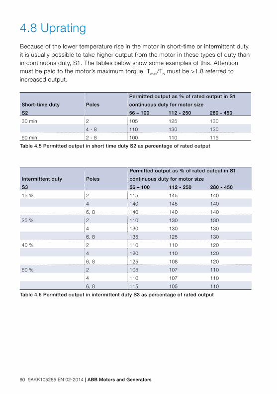
4.8 UpratingBecause of the lower temperature rise in the motor in short-time or intermittent duty, it is usually possible to take higher output from the motor in these types of duty than in continuous duty, S1. The tables below show some examples of this. Attention must be paid to the motor’s maximum torque, Tmax/TN must be >1.8 referred to increased output.
Short-time duty
S2
Poles
Permitted output as % of rated output in S1
continuous duty for motor size
56 – 100 112 - 250 280 - 450
30 min 2 105 125 130
4 - 8 110 130 130
60 min 2 - 8 100 110 115
Table 4.5 Permitted output in short time duty S2 as percentage of rated output
Intermittent duty
S3
Poles
Permitted output as % of rated output in S1
continuous duty for motor size
56 – 100 112 - 250 280 - 450
15 % 2 115 145 140
4 140 145 140
6, 8 140 140 140
25 % 2 110 130 130
4 130 130 130
6, 8 135 125 130
40 % 2 110 110 120
4 120 110 120
6, 8 125 108 120
60 % 2 105 107 110
4 110 107 110
6, 8 115 105 110
Table 4.6 Permitted output in intermittent duty S3 as percentage of rated output

ABB Motors and Generators | 9AKK105285 EN 02-2014 61
4.9 Efficiency and types of lossesEfficiency of a motor is a measure of how well it is capable of converting electrical energy into mechanical work. Lost energy is emitted in the form of heat. To increase efficiency, losses have to be reduced.
Motor losses can be divided into five main categories. The first two are classified as no-load losses because they remain constant regardless of the load. The first category is iron losses in the core, the second windage and friction losses. Load losses, which vary with the load, are classified into copper losses in the stator, rotor losses, and stray load losses. All losses can be influenced by motor design and construction solutions.
No-load lossesIron losses in the core are caused by the energy required to overcome the opposition to changing magnetic fields in the core material. These losses can be reduced by using better-quality steel and by lengthening the core to reduce magnetic flux density.
Windage and friction losses are caused by air resistance and bearing friction. Improved bearing design and bearing seal selection, air flow and fan design affect these losses. The fan must be large enough to provide adequate cooling, but not so large as to reduce efficiency and increase noise. To reach an optimal cooling effect in each ABB motor, blade sizes and pitches vary in different fan models.
Load lossesOf load losses, stator copper losses (also referred to as I2R losses) are caused by heating from the current flow through the resistance of the stator winding. Techniques for reducing these losses include optimizing the stator slot design.
Rotor losses are caused by rotor currents and iron losses. These losses are reduced for example by increasing the size of the conductive bars and end rings to produce lower resistance. Stray load losses are the result of leakage fluxes induced by load currents. These can be decreased by improving slot geometry.
Completely new motor designs are also developed to increase efficiency beyond known limits. The synchronous reluctance motor is an example of these new designs.
Efficiency values for rated output are listed in the technical data tables in ABB product catalogs.

62 9AKK105285 EN 02-2014 | ABB Motors and Generators
4.10 Power factorA motor consumes both active power, which it converts into mechanical work, and reactive power, which is needed for magnetization and which is not converted to work.
The active and reactive power, represented in the diagram (below) by P and Q, together give the apparent power S. The ratio between active power, measured in kW, and apparent power, measured in kVA, is known as the power factor. The angle between P and S is usually designated as ϕ, and the power factor itself is designated as cos ϕ.
Power factor is usually between 0.7 and 0.9. It is lower for small motors and higher for large motors.
Power factor is determined by measuring the input power, voltage and current at rated output power. The power factor stated is subject to a tolerance of (1-cos ϕ)/6 .
If there are many motors in an installation, a lot of reactive power will be consumed and therefore the power factor will be lower. For this reason, power suppliers sometimes require the power factor of an installation to be increased. This is done by connecting capacitors to the supply which absorb reactive power and thus raise the power factor.
Phase compensationWith phase compensation, the capacitors are usually connected in parallel with the motor, or with a group of motors. However, in some cases, over-compensation can cause an induction motor to self-excite and run as a generator. Therefore, to avoid complications, it is a normal practice not to compensate for more than the no-load current of the motor.
The capacitors must not be connected in parallel with single phases of the winding; such an arrangement may make the motor difficult or impossible to start with star-delta starting.
If a two-speed motor with separate windings has phase compensation on both windings, the capacitors should not remain in circuit on the unused winding.
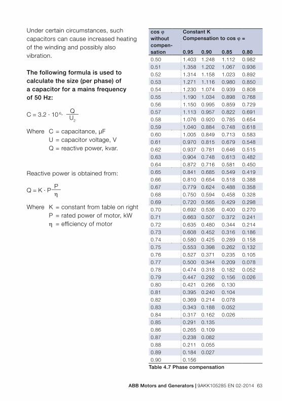
ABB Motors and Generators | 9AKK105285 EN 02-2014 63
cos ϕ without compen- sation
Constant KCompensation to cos ϕ =
0.95 0.90 0.85 0.80
0.50 1.403 1.248 1.112 0.982
0.51 1.358 1.202 1.067 0.936
0.52 1.314 1.158 1.023 0.892
0.53 1.271 1.116 0.980 0.850
0.54 1.230 1.074 0.939 0.808
0.55 1.190 1.034 0.898 0.768
0.56 1.150 0.995 0.859 0.729
0.57 1.113 0.957 0.822 0.691
0.58 1.076 0.920 0.785 0.654
0.59 1.040 0.884 0.748 0.618
0.60 1.005 0.849 0.713 0.583
0.61 0.970 0.815 0.679 0.548
0.62 0.937 0.781 0.646 0.515
0.63 0.904 0.748 0.613 0.482
0.64 0.872 0.716 0.581 0.450
0.65 0.841 0.685 0.549 0.419
0.66 0.810 0.654 0.518 0.388
0.67 0.779 0.624 0.488 0.358
0.68 0.750 0.594 0.458 0.328
0.69 0.720 0.565 0.429 0.298
0.70 0.692 0.536 0.400 0.270
0.71 0.663 0.507 0.372 0.241
0.72 0.635 0.480 0.344 0.214
0.73 0.608 0.452 0.316 0.186
0.74 0.580 0.425 0.289 0.158
0.75 0.553 0.398 0.262 0.132
0.76 0.527 0.371 0.235 0.105
0.77 0.500 0.344 0.209 0.078
0.78 0.474 0.318 0.182 0.052
0.79 0.447 0.292 0.156 0.026
0.80 0.421 0.266 0.130
0.81 0.395 0.240 0.104
0.82 0.369 0.214 0.078
0.83 0.343 0.188 0.052
0.84 0.317 0.162 0.026
0.85 0.291 0.135
0.86 0.265 0.109
0.87 0.238 0.082
0.88 0.211 0.055
0.89 0.184 0.027
0.90 0.156Table 4.7 Phase compensation
Under certain circumstances, such capacitors can cause increased heating of the winding and possibly also vibration.
The following formula is used to calculate the size (per phase) of a capacitor for a mains frequency of 50 Hz:
C = 3.2 · 10 6· Q____U2
Where C = capacitance, μFU = capacitor voltage, VQ = reactive power, kvar.
Reactive power is obtained from:
Q = K · PP___η
Where K = constant from table on rightP = rated power of motor, kW
η = efficiency of motor
64 9AKK105285 EN 02-2014 | ABB Motors and Generators
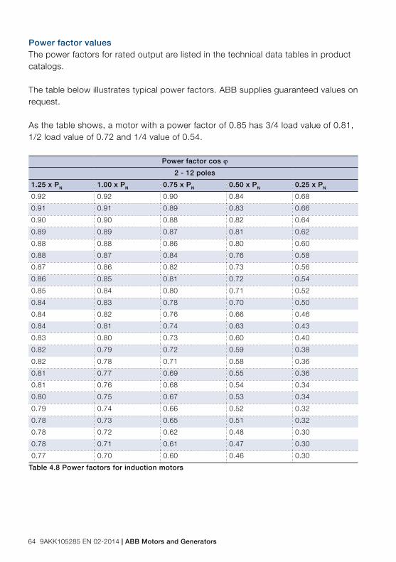
Power factor valuesThe power factors for rated output are listed in the technical data tables in product catalogs.
The table below illustrates typical power factors. ABB supplies guaranteed values on request.
As the table shows, a motor with a power factor of 0.85 has 3/4 load value of 0.81, 1/2 load value of 0.72 and 1/4 value of 0.54.
Power factor cos ϕ
2 - 12 poles
1.25 x PN 1.00 x PN 0.75 x PN 0.50 x PN 0.25 x PN
0.92 0.92 0.90 0.84 0.68
0.91 0.91 0.89 0.83 0.66
0.90 0.90 0.88 0.82 0.64
0.89 0.89 0.87 0.81 0.62
0.88 0.88 0.86 0.80 0.60
0.88 0.87 0.84 0.76 0.58
0.87 0.86 0.82 0.73 0.56
0.86 0.85 0.81 0.72 0.54
0.85 0.84 0.80 0.71 0.52
0.84 0.83 0.78 0.70 0.50
0.84 0.82 0.76 0.66 0.46
0.84 0.81 0.74 0.63 0.43
0.83 0.80 0.73 0.60 0.40
0.82 0.79 0.72 0.59 0.38
0.82 0.78 0.71 0.58 0.36
0.81 0.77 0.69 0.55 0.36
0.81 0.76 0.68 0.54 0.34
0.80 0.75 0.67 0.53 0.34
0.79 0.74 0.66 0.52 0.32
0.78 0.73 0.65 0.51 0.32
0.78 0.72 0.62 0.48 0.30
0.78 0.71 0.61 0.47 0.30
0.77 0.70 0.60 0.46 0.30
Table 4.8 Power factors for induction motors

ABB Motors and Generators | 9AKK105285 EN 02-2014 65
4.11 Air flow and air speedWhen the motor is ordered without self-cooling, attention must be paid to ensure sufficient cooling by other means. Air flow and air speed between the ribs of the motor frame must at the minimum meet the values given in the table below. The values correspond to 50 Hz network supply; with 60 Hz supply an increase of 20 % is needed.
Shaft height
Pole number
Air speed m/s
Air flow m3/s
Shaft height
Pole number
Air speed m/s
Air flow m3/s
280 2 9.6 0.46 355 2 10 0.82
4 8.5 0.39 4 13 1.1
6 6.5 0.32 6 11.5 1.0
8 7.6 0.36 8 8.5 0.7
315 SM. ML 2 8.3 0.46 400 2 15 1.4
4 9.4 0.56 4 13 1.25
6 7.5 0.4 6 11 1.1
8 7.6 0.43 8 8 0.8
315 LK 2 7.8 0.47 450 2 15 2.0
4 15 0.80 4 15 2.0
6 9.5 0.53 6 13 1.7
8 8.8 0.49 8 10 1.25
Table 4.9 Air flow and air speed

66 9AKK105285 EN 02-2014 | ABB Motors and Generators
1. Two separate windings Y/Y
2. Two separate windings ∆/∆
3. Dahlander-connection ∆/YY
4. Dahlander-connection Y/YY
4.12 Connection diagramsConnection of three phases, single speed motors
Δ-connection Y connection
Figure 4.7 Connection options for two-speed motors
Connection of two-speed motorsTwo-speed motors are normally connected as illustrated below; direction of rotation is discussed in the Standards chapter. Motors of normal design have six terminals and one earth terminal in the terminal box. Motors with two separate windings are normally Δ-Δ connected. They can also be Y/Y, Y/Δ or Δ/Y connected. Motors with one winding, Dahlander-connection, are connected Δ/YY when designed for constant torque drives. For a fan drive, the connection is Y/YY.
A connection diagram is supplied with every motor.
When starting a motor using Y Δ connection, always refer to the connection diagram supplied by the starter manufacturer.
Figure 4.6 Connection of three-phase single-speed motors

ABB Motors and Generators | 9AKK105285 EN 02-1014 67
5. Mechanical design
5. Mechanical design 685.1 Motor construction 695.2 Frame constructions 705.3 Terminal boxes 715.4 Bearings 735.5 Drain holes and humidity 745.6 External radial and
axial forces of the motor 755.7 Balancing 755.8 Vibration 765.9 Surface teatment 77

68 9AKK105285 EN 02-2014 | ABB Motors and Generators
This chapter introduces the main parts of an induction motor and the mechanical design of the parts that are of highest interest from motor usage point of view: the frame and terminal box, bearings, and drain holes.
The basics of radial and axial forces as well as the standards that define requirements for motor balancing, vibration measurement, and surface treatment are also discussed.
Mechanical design
ABB Motors and Generators | 9AKK105285 EN 02-1014 69
Mechanical design5.1 Motor constructionThe induction motor is an electric motor that uses electric power to induce rotation of the rotor. The main parts of the induction motor and their functions are as follows.
Stator - the stationary part of the motor which surrounds the rotor. The stator consists of copper wires (windings) wound in between the stator’s slots to carry supply current and to induce a rotating magnetic field to interact with the rotor.
Rotor - the rotating core part of the motor fixed to the shaft. The rotor consists of a stack of thin steel laminations and a squirrel-cage construction of conductive bars that react with the magnetic field of the motor and produce torque to turn the shaft.
Shaft - the rotating innermost part of the motor which transmits the rotor’s rotational power to the application fixed to the motor’s D-end.
Bearing - bearings surround the motor’s shaft at both ends and reduce friction between the motor frame and shaft.
Frame – cast-iron or aluminum casing which covers the motor’s core parts and provides electrical connections.
D-end - the drive end of the motor.
N-end - the non-drive end of the motor.
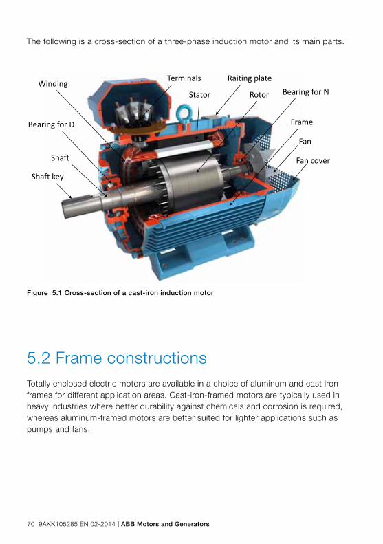
70 9AKK105285 EN 02-2014 | ABB Motors and Generators
Winding
Bearing for D Frame
Bearing for N
Shaft key
Terminals Raiting plate
Fan
Fan cover
RotorStator
Shaft
Figure 5.1 Cross-section of a cast-iron induction motor
5.2 Frame constructionsTotally enclosed electric motors are available in a choice of aluminum and cast iron frames for different application areas. Cast-iron-framed motors are typically used in heavy industries where better durability against chemicals and corrosion is required, whereas aluminum-framed motors are better suited for lighter applications such as pumps and fans.
The following is a cross-section of a three-phase induction motor and its main parts.

ABB Motors and Generators | 9AKK105285 EN 02-1014 71
5.3 Terminal boxes The terminal box is mounted either on top of the motor or on either side of the motor. Technical details may vary from type to type, and the most recent information can be found in the relevant product catalogs.
The terminal boxes of aluminum motors in sizes 56 to 180 are normally provided with knock-out openings, and sizes 200 to 250 have terminal boxes with two gland plates.
The terminal boxes of cast-iron motors in sizes 71 to 250 are equipped with blank cover plates for connection flanges. In motor sizes 280 to 450, the terminal box is equipped with cable glands or cable boxes (Figures 5.2 and 5.3). There is a wide range of cable glands and cable boxes available as options, also equipped with EMC modules and cable clamps.
The terminal box material is either cast iron or aluminum, depending on the motor type. The main terminal box is attached either on top, on side, or at a 45 degree angle on the side. It may also be connected to the motor with extended cables, so-called flying leads. In case of accessories such as thermistors or heating elements, one or more auxiliary terminal boxes may be attached to the motor. Non-standard designs of terminal boxes, such as non-standard size and degree of protection, are available as options.
A standard motor usually has six phase connections and at least one earthing connection (Figures 5.4 and 5.5). The necessary connection parts and a connection diagram are delivered together with the motor, under the terminal box cover
Figure 5.2 Connection flange with cable Figure 5.3 Angle adapter and cable-sealing glands box

72 9AKK105285 EN 02-2014 | ABB Motors and Generators
Figures 5.4–5.5 Typical terminal boxes in motor sizes 71 to 250 (5.4) and 280 to 315 (5.5)
The terminal box in aluminum motors allows cable entry from both sides. In small motors, the box is integrated in motor frame and has a blind flange on with knock-out openings on both sides (Figure 5.6). Larger aluminum motors are equipped with two connection flanges on both sides. In cast iron motor sizes 71 – 132, the box is integrated in the frame, with connection on the right-hand side (viewed from the D-end). Sizes 160 – 355 have a terminal box that can be rotated 4x90°, and sizes 400 – 450 have a terminal box that can be rotated 2x180° to allow cable entry from either side of the motor. The 4x90° turnable box is available as an option for several other motor types as well.
The degree of protection of a standard terminal box is IP 55.
Figure 5.6 Terminal box integrated in motor frame
To ensure that suitable connections are supplied for the terminal box, see the specific product catalog for information on flange openings, cable diameters, and so forth.

ABB Motors and Generators | 9AKK105285 EN 02-1014 73
5.4 Bearings Motors are normally fitted with single row deep groove ball bearings. The complete bearing designation is stated on the rating plate of most motor types.
If the bearing in the D-end of the motor is replaced with roller bearings NU- or NJ-, higher radial forces can be handled. Roller bearings are especially suitable for belt-driven applications.
With high axial forces, angular contact ball bearings should be used. This type of bearing is usually needed when motors are mounted vertically. When ordering a motor with angular contact ball bearings, the method of mounting and direction and magnitude of axial force must be specified.
Single angular contact bearings are not suitable for horizontally mounted motors where low axial forces are possible. Double angular contact ball bearings arranged back to back or face to face are recommended in case there are low axial forces in a horizontally mounted motor, or if the direction of the axial force can change. See the product catalog of the motor in question for more specific information about bearings.
Bearing life The normal bearing life L10h of a bearing is defined, according to ISO 281, as the number of operating hours achieved or exceeded by 90 % of identical bearings in a large test series under specific conditions. 50 % of bearings achieve at least five times this lifetime.
The nominal bearing life is the lifetime that 90 % of identical bearings achieve or exceed before first signs of material weariness appear. A sufficient grease layer inside the bearing and usage in a correct application are preconditions for a nominal bearing life. By definition, 10 % of bearings can fail before they reach the nominal bearing life. Consequently, bearing life should never be confused with warranty period.
The usual values for bearing lifetime of standard motors are 40,000 h for belt drive and 100,000 h for direct coupling.

74 9AKK105285 EN 02-2014 | ABB Motors and Generators
Bearing sizeReliability is the main criteria for bearing size design, taking into account the most common types of application, load of the motor and motor size. ABB uses series 63 bearings which are of robust design for longer life and higher loadability. 62 series bearings have lower noise levels, higher maximum speeds, and lower losses.See product catalogs and motor rating plates for exact bearing types.
Figure 5.7 Bearing arrangements in Process performance cast iron motors, sizes 280 to 450
5.5 Drain holes and humidityAbsolute humidity is the amount of water (g/m3) in a certain volume of air. Its value, so-called saturation value, increases when temperature increases. Relative humidity is the ratio between absolute air humidity and saturation value at a certain ambient temperature. When air cools below the temperature where the dew point is reached (relative humidity is 100 %), condensation on cold surfaces takes place.
Humidity is a risk not only to the external surface of the motor; it may also lead to internal corrosion.
When totally enclosed machines heat up, the air inside them expands; whenthey cool down the air volume decreases. The volume increase and decrease depend on the temperature difference to the ambient air. When the motor cools down, it may suck in particles and humidity that could damage bearings and insulation. The advantage of the drain holes is that they prevent ventilation through bearings and terminal box. Drain holes can be opened and closed with plastic plugs.

ABB Motors and Generators | 9AKK105285 EN 02-1014 75
When temperature difference to ambient air is high, heating elements fitted to the winding heads may be needed to prevent corrosion of the windings. If humidity inside the motor is suspected, special measures such as insulation resistance measurement or drying in an oven need to be taken to avoid permanent damage to the motor.
5.6 External radial and axial forces of the motor
Depending on the purpose of use, and in addition to the rotational torque which is always present when running the motor, the shaft end may be affected by external radial or axial forces. Radial forces are those that are perpendicular to the shaft, while axial forces are linear with the shaft. The shaft end may also be exerted by both radial and axial forces at the same time. The maximum radial and axial forces are given in product catalogs per each motor type in Newtons. In case of radial forces, it is essential to know the exact position of the load on the shaft extension. If the shaft extension will be affected simultaneously by both radial and axial forces, the load capacity of the motor needs to be checked case by case with ABB.
5.7 BalancingThe rotor is dynamically balanced in the keyway of the shaft extension with a half-sized key (half-key balancing) according to standard ISO 8821. Balancing with a full key or without a key are also available on request. By default, ABB motors are balanced to grade G2.5 according to ISO 1940/1. Balancing to grade G1 is available on request. When the motor is ordered with higher vibration class B (see Vibration), the rotor balancing grade is G1 by default.
There are two possibilities for checking balancing quality afterwards: removing the rotor out of the motor and placing it on a balancing machine, or checking it by a vibration measurement tool. The latter can be done as follows: Lift the motor with a lifting lug and leave it hanging, or place it standing on soft rubber, for example. Run the motor at nominal speed and check vibration level. The measured vibration level should be less than 1.5 mm/s (rms) for a new motor.

76 9AKK105285 EN 02-2014 | ABB Motors and Generators
5.8 Vibration
Figure 5.8 Vibration testing
Effective values (root mean squares, rms) of vibration velocity are defined in the IEC 60034-14 standard (see Table 5.1). Requirements apply across the measuring range of 10 to 1000 Hz. The purpose of this standard is to measure the vibration behavior of a machine alone at no load, under defined conditions in a reproducible and comparable way, the motor placed on elastic mounting. However, though vibration severity depends on the balancing grade used, it also essentially depends on the properties of coupling to the driven machine and coupling parts used.
Possible origins of severe vibration of coupled motors can be incorrect balancing (half key/full key), inaccurate alignment of the motor with a coupled machine, and resonance of the system (motor and foundation). ABB motors fulfill grade A vibration level by default.
Vibration is expressed in mm/s RMS.
Vibrationgrade
Shaft height, mmmounting
56 ≤ H ≤ 132 132 < H ≤ 280 H > 280
Displac.μm
Vel.mm/s
Acc.m/s2
Displac. μm
Vel.mm/s
Acc.m/s2
Displac. μm
Vel.mm/s
Acc. m/s2
A Rigid mounting 25 1.6 2.5 35 2.2 3.5 45 2.8 4.4
Free suspension 21 1.3 2.0 29 1.8 2.8 37 2.3 3.6
B Free suspension 11 0.7 1.1 18 1.1 1.7 29 1.8 2.8
Rigid mounting - 14 0.9 1.4 24 1.5 2.4
Table 5.1 Limits of maximum vibration magnitude in displacement, velocity and acceleration (rms) for shaft height H

ABB Motors and Generators | 9AKK105285 EN 02-1014 77
5.9 Surface treatment The surface treatment categorization of ABB motors is based on the ISO 12944 standard. ISO 12994-5 divides paint system durability into three categories: low (L), medium (M), and high (H). Low durability corresponds to a lifetime of 2 – 5 years, medium to 5 – 15 years, and high durability to over 15 years.
The durability range is not a guaranteed lifetime. Its purpose is to help the owner of the motor plan for appropriate maintenance intervals. More frequent maintenance may be required because of fading, chalking, contamination, wear and tear, or for other reasons.
ABB’s standard surface treatment is corrosivity category C3, durability range M (which corresponds to medium corrosivity and medium durability). Special surface treatment is available in corrosivity categories
C4 and C5-M, durability class M for both. See table below for more details. In addition, surface treatment according to the NORSOK standard for offshore environments is available as an option.
The standard ABB paint color for motors is Munsell blue 8B 4.5/3.25.
Corrosivity category
Outdoor atmospheres Indoor atmospheres Use in ABB motors
C1, very low Not used Heated buildings with clean atmospheres
Not available
C2, low Atmospheres with low level pollution, mostly rural areas.
Unheated buildings where condensation may occur, such as depots and sports halls.
Not available
C3, medium Urban and industrial atmos-pheres, moderate sulfur dioxide pollution. Coastal areas with low salinity.
Production rooms with high humidity and some air pollution; food processing plants, laundries, breweries, dairies.
Standard treatment
C4, high Industrial areas and coastal areas with moderate salinity.
Chemical plants, swimming pools, coastal ship- and boatyards.
Optional treatment, variant code 115
C5-I, very high (industrial)
Industrial areas and coastal areas with high humidity and aggressive atmosphere.
Buildings or areas with nearly permanent condensation and high pollution.
Not available
C5 -M, very high (marine)
Coastal and offshore areas with high salinity.
Buildings or areas with nearly permanent condensation and high pollution.
Optional treatment, variant code 754
Table 5.2 Atmospheric corrosivity categories and recommended environment

78 9AKK105285 EN 02-2014 | ABB Motors and Generators

ABB Motors and Generators | 9AKK105285 EN 02-2014 79
6. Noise
6. Noise 806.1 Sound pressure level and
sound power level 816.2 Weighting filters 826.3 Octave bands 836.4 Additional sound sources 846.5 Noise components of a motor 856.6 Airborne and structure borne noise 876.7 Sound pressure levels 88

80 9AKK105285 EN 02-2014 | ABB Motors and Generators
NoiseNoise is subject to strict regulations today, with maximum permitted levels. Accordingly, ABB considers noise reduction a major design criterion in the development of our motors.

ABB Motors and Generators | 9AKK105285 EN 02-2014 81
Noise6.1 Sound pressure level and sound power level
Sound is pressure waves sent out by a source through the medium (usually air)in which it is immersed. Sound pressure is measured in decibels (dB) during anoise test. The ratio between the threshold of hearing and the threshold of painis 1:10 000 000. As the pressure scale is so large and since we experience a 10 dB difference as a doubling of the perceived sound level, a logarithmic scale is employed where:
Sound pressure level Lp= 10 log [(p/p0)2 ] [dB]
p0 = 20 μPa is the threshold of hearing for an average person
p = measured pressure [Pa]
Sound pressure is measured in a test room to eliminate the effect of reflected noise and external sources. A microphone is placed at various positions around the motor in order to measure sound radiation into different directions. Usually the distance of the microphone from the motor surface is one meter. As the noise level varies in different directions due to the influence of internal sources, a tolerance of 3 dB is applicable for the average sound pressure level. Information on sound pressure level is meaningful only if the distance from the sound source is stated. For example, Lp = 80 dB at a distance of one meter from a point sound source corresponds to 70 dB at three meters.
The measured sound level Lp can be converted into power radiated from the sound source, to determine the sound power level Lw. The formula for this is: Lw = Lp + Ls (Ls is calculated from the area of the measurement surface, according to DIN). Thus, sound power level is usually a larger number than the corresponding sound pressure level. Care should be taken not to confuse the quantities. Figure 6.1 Human hearing range

82 9AKK105285 EN 02-2014 | ABB Motors and Generators
The use of sound power instead of sound pressure to describe noise emission from a motor is encouraged: because sound pressure is a function of distance and environmental factors (reflections), sound power is fixed. There is an analogy to heating radiator: If you use a 1000 W electrical heater to warm up a room, the final temperature of the room depends on the insulation of the walls, room size etc. Here the temperature is analog to sound pressure.
6.2 Weighting filtersAmplifiers and various filters are used when measuring composite sound. dB figures measured in this way have A, B, or C added after them, depending on which filter is used. Normally only the LpA figure is given. It corresponds best with the perception of the ear.
Filters let through an entire frequency range, but attenuate or amplify certain parts of it. The resulting frequency curves resemble stylized 40-, 70- and 100-phon curves for pure tones.
Figure 6.2 Filter characteristics for A-, B-, and C-weighting

ABB Motors and Generators | 9AKK105285 EN 02-2014 83
NR Time per day
85 > 5 hours
90 = 5 hours
95 = 2 hours
105 < 20 minutes
120 < 5 minutes
A ____ No risk of hearing damage. The NR 85 curvetouches the noise curve of the motor.The noise level is 88 dB(A).
B ----- Risk of hearing damage. The NR 88 curve touches the noise curve of the motor.The noise level is 90 dB(A).
6.3 Octave bandsMean sound pressure level is measured with a broad band filter covering the entire frequency band. Measurement is also done with a narrow band filter to define noise level per octave band (frequency band), as the perception of the human ear is dependent on the octave band.
Octave band analysisTo get an idea of the character of composite sound, it has proven practical to divide the frequency range into octave bands with a ratio of 1:2 between the band limit frequencies. The frequency range is usually referred to by the mid-frequency of the band. The measured dB figures for all octave bands are generally shown in the form of an octave band diagram.
A system of noise rating curves known as NR curves has been developed under ISO to express the subjective degree of disturbance from different noises. These curves are intended to be used when assessing the risk of damage to hearing. Similar systems are also available. NR curve numbers signify the degree of noise.
For the octave band with a mid-frequency of 1,000 Hz, the number is equal to the sound pressure level in dB. The NR curve that touches the noise curve of the motor in question determines the motor’s noise rating. The table below illustrates the use of noise rating. It shows how long a person can remain in a noisy environment without getting permanent hearing damage.
Figure 6.3 Noise rating (NR) curves

84 9AKK105285 EN 02-2014 | ABB Motors and Generators
6.4 Additional sound sourcesPerception of difference in sound levelA difference of 1 dB in sound level is barely detectable, whereas a 10 dB difference is perceived as doubling or halving of the sound level.
The diagrams below illustrate the total sound pressure level when several sound sources are present. For example, diagram A shows that the sound pressure level will be 3 dB higher if the sound levels of two identical sources are added together. Diagram B shows how the sound level pressure changes when the sound sources have different pressure levels.
However, before logarithmic values can be added or subtracted, they must be converted into absolute numbers. An easier way of adding or subtracting sound sources is to use the diagrams below.
Figure 6.4 Effect of sound sources on total sound pressure level
Adding several equal sound sources. Adding together two such sources increases the total level by 3 dB; adding together four increases it by 6 dB, and so on.
Adding two different levels. When the difference between the two sound pressure levels is greater than 10 dB, the lower level contributes so little to the total sound pressure level it may be disregarded.
Increase in total sound pressure level Increase in total sound pressure level

ABB Motors and Generators | 9AKK105285 EN 02-2014 85
6.5 Noise components of a motorThe total sound power emission from a motor can be considered a combination of three uncorrelated noise sources acting together. These sources are magnetic, cooling, and mechanical or rotational noise sources. Magnetic noise results from temporal and spatial variations of magnetic force distribution in the air gap. Operating a cooling fan creates most of the cooling noise. Rotational noise is generated when 1) an unsmooth body (rotor) rotates in a cavity that has obstacles and discontinuities, and 2) the shaft and the bearings interact. The magnitude of each source depends on motor type. The major factors affecting each of the sources in a motor are:
Magnetic noise Pmagn [W] − shaft load − voltage, current, frequency, and supply type − winding parameters − slot geometry − saturation, eccentricity, etc.
Cooling noise Pcool [W] − fan type: axial, radial, or mixed flow − rotational speed and fan diameter − airflow velocity − cooling method; closed vs. open, water vs. air
Mechanical or rotational noise Prot [W] − type of cooling: closed or open − type of bearings − speed
The total sound power level LWtot of an electrical machine in decibels can be expressed as
LWtot = 10 log10
Here Pref = 1 pW is the reference sound power. The equation shows that the total sound power level of an electrical machine is the result of all of the sources.
Pmagn + Pcool + Prot
Pref
86 9AKK105285 EN 02-2014 | ABB Motors and Generators
The equation is useful in considering the reduction of the total sound power of an electrical machine. Reduction measures should first be applied to the most dominant source. The following examples clarify this concept:
− For a 2-pole directly-cooled motor, the cooling noise produces 99 % of the total sound power, which means that neither the loading nor the converter supply will increase the total sound power level of the machine.
− For an 8-pole totally-closed machine with water cooling, magnetic noise dominates the total noise output and thus the loading and/or the converter supply will increase the sound power level to some extent.
− With sinusoidal supply, loading the machine can increase the magnetic sound output significantly, but with frequency converter supply, the increase of the noise output is usually much smaller.
− Cooling noise can be reduced by optimized fan design. Similarly, increasing the overall efficiency of the motor means that fan diameter can be reduced. However, the fan must be large enough to generate sufficient air flow so that adequate cooling of the motor is ensured.
− The noise level of larger motors can be reduced by fitting a silencer. On larger 2-pole motors, a unidirectional fan which rotates in one direction only and so generates less noise can be used.
− At fixed PWM converter duty, the motor noise produced in certain octave bands can change considerably depending on the switching frequency of the converter. The converter does not produce sinusoidal voltage. However, as ABB Direct Torque Control converters do not have a fixed switching frequency, the noise level is lower than would be the case if a fixed switching frequency converter was used with the same motor.

ABB Motors and Generators | 9AKK105285 EN 02-2014 87
6.6 Airborne and structure-borne noiseNoise can be propagated in two ways. Airborne noise caused by the vibration of the motor’s surface is propagated by air. Structure-borne noise is caused by the bearings, and by magnetic noise vibrating through the motor’s frame, foundation, walls and any pipe work.
Airborne noiseDepending on the application, airborne noise can be reduced by fitting a silencer or an unidirectional fan.
Structure-borne noiseAn effective method of eliminating structure-borne noise is to mount accurately dimensioned vibration dampers. Choosing vibration dampers arbitrarily, could, however, worsen the noise problem.

88 9AKK105285 EN 02-2014 | ABB Motors and Generators
6.7 Sound pressure levelsThe following two tables present sound pressure levels for Process performance motors in a 400 V network, at 50 Hz net duty. We still use sound pressure to describe noise levels in low voltage motors, because much of reference data uses the same quantity.
To roughly convert sound pressure level into sound power, simply add the reference value in the last column to the given sound pressure value. Both quantities are indicated in decibel. The given conversion values are only approximate and will vary also according to motor length and type
Framesize
2poles dB(A)
4polesdB(A)
6polesdB(A)
8polesdB(A)
Add to get sound power
63 54 40 38 32 5
71 58 45 42 43 6
80 60 50 47 50 6
90 63 50 44 52 7
100 62 63 49 53 7
112 68 64 56 55 8
132 73 66 61 58 8
160 69 65 59 59 9
180 69 62 59 59 9
200 72 63 63 68 10
225 74 66 63 60 10
250 75 67 63 63 11
280 75 67 63 63 11
Framesize
2 poles dB(A)
4 polesdB(A)
6 polesdB(A)
8 polesdB(A)
Add to get sound power
71 58 45 42 43 6
80 60 50 47 50 6
90 69 56 44 53 7
100 68 58 49 53 7
112 70 59 66 55 8
132 70 67 57 58 8
160 69 62 59 59 9
180 69 62 59 59 9
200 72 63 63 60 10
225 74 66 63 63 10
250 75 67 66 65 11
280 77 75 70 72 12
315 78 78 70 72 13
355 83 78 75 75 14
400 82 78 77 71 15
450 85 85 81 80 15
Table 6.2 Sound pressure levels for cast iron motors
Table 6.1 Sound pressure levels for aluminum motors

ABB Motors and Generators | 9AKK105285 EN 02-2014 89
7. Installation and maintenance
7. Installation and maintenance 907.1 Delivery acceptance 917.2 Insulation resistance check 917.3 Torque on terminals 927.4 Operation 927.5 Handling 937.6 Foundations 947.7 Coupling alignment 957.7.1 Mounting pulleys and coupling halves 967.8 Slide rails 977.9 Mounting bearings 987.10 Lubrication 987.11 Fuse rating 99

90 9AKK105285 EN 02-2014 | ABB Motors and Generators
Each motor must be installed and maintained in accordance with the manual included in the delivery of the motor. The installation and maintenance instructions in this chapter are a generic guideline.
Installation and maintenance

ABB Motors and Generators | 9AKK105285 EN 02-2014 91
Installation and maintenance7.1 Delivery acceptance1. When delivered, inspect the equipment for transit damages. If any damages arefound, inform the forwarding agent immediately.
2. Check data on the rating plate. Pay special attention to voltage and windingconnection (star or delta).
3. Remove transit locking if fitted, and turn shaft by hand to verify that it rotatesfreely.
7.2 Insulation resistance checkBefore commissioning the motor, or when winding dampness is suspected, insulation resistance measurement is required.
Resistance, corrected to 25 ºC, must exceed the reference value, 10 MΩ (measured with 500 V or 1000 V DC). The insulation resistance value is halved for each 20 ºC rise in ambient temperature.
WARNING: The motor frame must be grounded and windings discharged against the frame immediately after measurement to avoid the risk of electric shock.
If the reference resistance value is not attained, the winding is too damp and must be oven-dried at 90 ºC for 12 - 16 hours, followed by 105 ºC for 6 - 8 hours. Drain hole plugs, if fitted, must always be removed before oven-drying, and closing valves, if fitted, must be opened.
Windings drenched in seawater normally need to be rewound.
!

92 9AKK105285 EN 02-2014 | ABB Motors and Generators
7.3 Torque on terminalsThe following torque table is a generic guideline for tightening torques. The motor’s frame material and surface treatment must be taken into account when determining the tightening torque..
Thread 4.60 Nm 6.8 Nm 8.8 Nm 10.9 Nm 12.9 Nm
M2.5 0.24 - - - -
M3 0.42 - - - -
M5 2 4 5 8 9
M6 3 7 9 13 15
M8 8 16 21 33 37
M10 16 32 43 63 73
M12 27 55 73 108 126
M14 44 88 117 172 200
M16 67 134 180 264 309
M20 130 262 363 517 605
M22 176 353 495 704 824
M24 226 450 625 890 1040
M27 330 660 915 1300 1530
M30 450 900 1250 1780 2080
M33 610 - - - -
M36 780 - - - -
Table 7.1 Tightening torques for steel screws and nuts
7.4 OperationOperating conditionsLV motors are designed for use in industrial applications under the following conditions.
− Normal ambient temperature range from - 20 ºC to + 40 ºC − Maximum altitude 1,000 m above sea level − Tolerance for supply voltage is ±5 % and for frequency ±2 % according to
EN/IEC 600034-1 (2004).
ABB Motors and Generators | 9AKK105285 EN 02-2014 93
SafetyAll motors must be installed and operated by qualified personnel familiar with the relevant health and safety requirements and national legislation. Safety equipment necessary for the prevention of accidents at the installation and operation site must be provided in accordance with local requirements.
WARNING Small motors with supply current directly switched by thermally sensitive switches can start automatically.
Accident preventionNever stand on a motor. To prevent burns, the outer casing must not be touched during operation. Special instructions may also apply to certain motor applications such as frequency converter supply.
7.5 HandlingStorage
− Motors should always be stored in a dry, vibration-free and dust-free environment.
− Unprotected machined surfaces (shaft-ends and flanges) should be treated with an anti-corrosive.
− It is recommended that shafts are periodically rotated by hand to prevent grease migration.
− Anti-condensation heaters are recommended to avoid water condensation in the motor and should preferably be energized.
− The characteristics of electrolytic capacitors, if fitted to single-phase motors, will require “reforming” if stored over 12 months.
Transportation Motors fitted with cylindrical-roller and/or angular-contact bearings must be secured with locking devices during transport.
Motor weightThe total weight and the center of gravity of motors with the same frame size can vary because of different output, mounting arrangements and auxiliary equipment. The actual weight of the motor is marked on the rating plate.
!

94 9AKK105285 EN 02-2014 | ABB Motors and Generators
7.6 Foundations The end user of the motor has full responsibility for preparation of the foundation for the motor.
The foundation must be smooth, level and, if possible, vibration free. A concrete foundation is therefore recommended. If a metal foundation is used, it should be treated with an anti-corrosive.
The foundation must be stable enough to withstand possible short-circuit forces. Short-circuit torque is primarily a damped sinusoidal oscillation and can thus have both positive and negative values. Stress on the foundation can be calculated with the help of data tables in the motor’s catalog and the formula below.
F = 0.5 x g x m + 4 x Tmax
A
Where F = stress per side, Ng = gravitational acceleration, 9.81 m/s2
m = motor weight, kg Tmax = maximum torque, Nm
A = lateral distance between the holes in the motor’s feet, m.
Dimension A is given in the motor’s dimension drawing in millimeters.
The foundation should be dimensioned to afford a sufficiently large resonance gap between the natural frequency of the installation and various interference frequencies.
Foundation studs The motor should be secured with foundation studs or a base plate. Motors for belt drives should be mounted on slide rails.
The foundation studs are bolted to the feet of the motor once locating pins have been inserted in the holes reamed for the purpose. The studs must be fitted to the correct feet with a 1 - 2 mm shim between the stud and the feet; see the markings on the studs and on the stator feet. Place the motor on the foundation and align the coupling. Use a spirit or laser level to verify that the shaft is horizontal. The height of the stator frame can be adjusted by setting either screws or shims. When you are sure the alignment is correct, grout the blocks.
ABB Motors and Generators | 9AKK105285 EN 02-2014 95
7.7 Coupling alignmentMotors must always be aligned accurately. This is particularly important in the case of directly coupled motors. Incorrect alignment can lead to bearing failure, vibration, and even shaft fracture. In the event of bearing failure or if vibration is detected, the alignment should be checked immediately.
The best way of achieving proper alignment is to mount a pair of dial gauges as shown (page 100). Each gauge is on a coupling half, and they indicate the difference between the coupling halves both axially and radially. Slowly rotating the shafts while observing the gauge readings gives an indication of the adjustment that need to be made. The coupling halves must be loosely bolted together so that they can easily follow each other when turned.
To determine whether the shafts are parallel, measure with a feeler gauge the distance between the outer edges of the coupling halves at a point on the periphery: see Figure 7.2. Then turn both halves together through 90° without changing the relative positions of the shafts, and measure again at exactly the same point. Measure the distance again after rotating 180° and 270°. For typical coupling sizes, the difference between the highest and lowest readings must not exceed 0.05 mm.
To check that the shaft centers are directly opposite each other, place a steel ruler parallel with the shafts on the turned periphery of one coupling half and then measure the clearance between the periphery of the other half and the ruler in four positions as a parallelism check. The difference between the highest and lowest readings must not exceed 0.05 mm.
When aligning a motor with a machine whose frame reaches another temperature than the motor itself in normal service, allowance must be made for the difference in shaft height resulting from different thermal expansion. For the motor, the increase in height is about 0.03 % from ambient temperature to operating temperature at full output. Mounting instructions from manufacturers of pumps, gear units etc. often state the vertical and lateral displacement of the shaft at operating temperature. Bear in mind the effects of thermal expansion to avoid vibration and other problems in service.

96 9AKK105285 EN 02-2014 | ABB Motors and Generators
Figure 7.2 Angular deviation and motor alignment
7.7.1 Mounting pulleys and coupling halvesCare must be taken when fitting pulleys and coupling halves to prevent damage to bearings. They must never be forced in place or levered out. The pulleys and coupling halves with interference fit are heated before installation. The heating of the pulley or coupling half can be done with an induction heater or a gas torch, or in an oven.
A coupling half or pulley with a sliding fit can be pushed onto the shaft by hand for about half the length of the shaft extension. A special tool or fully-threaded bolt, a nut and two flat pieces of metal are then used to push the coupling half or pulley fully home against the shoulder of the shaft.
a b
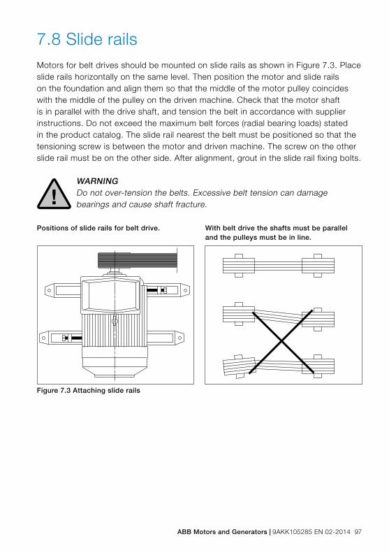
ABB Motors and Generators | 9AKK105285 EN 02-2014 97
7.8 Slide railsMotors for belt drives should be mounted on slide rails as shown in Figure 7.3. Place slide rails horizontally on the same level. Then position the motor and slide rails on the foundation and align them so that the middle of the motor pulley coincides with the middle of the pulley on the driven machine. Check that the motor shaft is in parallel with the drive shaft, and tension the belt in accordance with supplier instructions. Do not exceed the maximum belt forces (radial bearing loads) stated in the product catalog. The slide rail nearest the belt must be positioned so that the tensioning screw is between the motor and driven machine. The screw on the other slide rail must be on the other side. After alignment, grout in the slide rail fixing bolts.
WARNINGDo not over-tension the belts. Excessive belt tension can damage bearings and cause shaft fracture.!
Positions of slide rails for belt drive. With belt drive the shafts must be parallel and the pulleys must be in line.
Figure 7.3 Attaching slide rails

98 9AKK105285 EN 02-2014 | ABB Motors and Generators
7.9 Mounting bearingsAlways take special care with bearings. Bearings should be fitted by heating or with purpose-made tools and removed with pullers. The maximum heating temperature is 100 °C. Detailed information can be obtained from the bearing supplier.
When a bearing is mounted on the motor shaft, cold or hot mounting may be used. Cold mounting is only suitable for small bearings and bearings that do not have to be pressed far onto the shaft. For hot mounting and where the bearing is shrink-fitted on the shaft, the bearing is first heated in an oil bath or with a special heater. It is then pressed onto the shaft with a mounting sleeve that fits the inner ring of the bearing. Grease-filled bearings, which usually have sealing plates or shield plates, should not be heated.
7.10 LubricationReliability is a key driver in bearing design and in bearing lubrication systems. That is why ABB, as standard, follows the L1-principle: 99 per cent of motors will make the interval time). The lubrication intervals can also be calculated according to the L10 principle, which means that 90 per cent of motors will make the interval time. L10-values, which are normally doubled compared to L1-values, are available from ABB at request.
Motors with permanently greased bearingsMotors up to frame size 250 are normally fitted with permanently greased bearings of type Z or 2Z. Process performance motors are normally provided with grease nipples.
Guidelines for bearing lifetime − 4-pole motors: 20,000 – 40,000 duty hours1)
− 2 and 2/4-pole motors: 10,000 – 20,000 duty hours1) − Shorter intervals apply to larger motors.
1) Depending on the application and load conditions
Motors with a lubrication systemLubricate the motor when operational. If a grease outlet plug is fitted, remove it temporarily when lubricating, or remove permanently with auto-lubrication. If the motor is fitted with a lubrication plate, use the values shown on the plate; otherwise lubricate according to the L1 -principle.
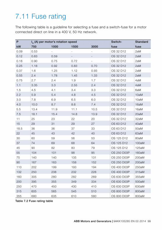
ABB Motors and Generators | 9AKK105285 EN 02-2014 99
7.11 Fuse rating The following table is a guideline for selecting a fuse and a switch-fuse for a motor connected direct on line in a 400 V, 50 Hz network.
P IN (A) per motor’s rotation speed Switch- Standard
kW 750 1000 1500 3000 fuse fuse
0.09 0.53 - - - OS 32 D12 2aM
0.12 0.63 0.59 - - OS 32 D12 2aM
0.18 0.90 0.75 0.72 - OS 32 D12 2aM
0.25 1.18 0.92 0.83 0.70 OS 32 D12 2aM
0.37 1.6 1.25 1.12 0.93 OS 32 D12 2aM
0.55 2.4 1.78 1.45 1.33 OS 32 D12 2aM
0.75 2.7 2.4 1.9 1.7 OS 32 D12 4aM
1.1 3.35 3.3 2.55 2.4 OS 32 D12 4aM
1.5 4.5 4.1 3.4 3.3 OS 32 D12 6aM
2.2 5.9 5.4 4.8 4.5 OS 32 D12 10aM
3.0 7.8 6.9 6.5 6.0 OS 32 D12 10aM
4.0 10.0 8.7 8.6 7.4 OS 32 D12 16aM
5.5 13.4 11.9 11.1 10.5 OS 32 D12 16aM
7.5 18.1 15.4 14.8 13.9 OS 32 D12 20aM
11 25 23 22 20 OS 32 D12 32aM
15 29 31 29 27 OS 63 D12 40aM
18.5 36 36 37 33 OS 63 D12 50aM
22 45 43 42 40 OS 63 D12 63aM
30 60 59 56 53 OS 125 D12 80aM
37 74 69 68 64 OS 125 D12 100aM
45 90 82 83 79 OS 125 D12 125aM
55 104 101 98 95 OS 250 D03P 160aM
75 140 140 135 131 OS 250 D03P 200aM
90 167 163 158 152 OS 250 D03P 200aM
110 202 199 193 194 OS 400 D03P 250aM
132 250 238 232 228 OS 400 D03P 315aM
160 305 280 282 269 OS 630 D03P 355aM
200 395 355 349 334 OS 630 D03P 500aM
250 470 450 430 410 OS 630 D03P 630aM
315 605 565 545 510 OS 800 D03P 800aM
355 680 635 610 580 OS 800 D03P 800aM
Table 7.2 Fuse rating table

100 9AKK105285 EN 02-2014 | ABB Motors and Generators

ABB Motors and Generators | 9AKK105285 EN 02-2014 101
8. The SI system
8. The SI system 1008.1 Quantities und units 1018.2 Prefixes 1028.3 Conversion factors 103

102 9AKK105285 EN 02-2014 | ABB Motors and Generators
The SI systemThis section explains some of the units in the International System of Units (SI) that are used in conjunction with electric motors and their application.
A distinction is made between quantity, quantity value, unit, measurement number and between the name and symbol of a unit. These distinctions are explained in the following example.
Example: P = 5.4 W, i.e. the power is 5.4 watts, where:
Quantity name = powerQuantity symbol = PQuantity value = 5.4 wattsUnit name = wattUnit symbol = WNumerical value = 5.4
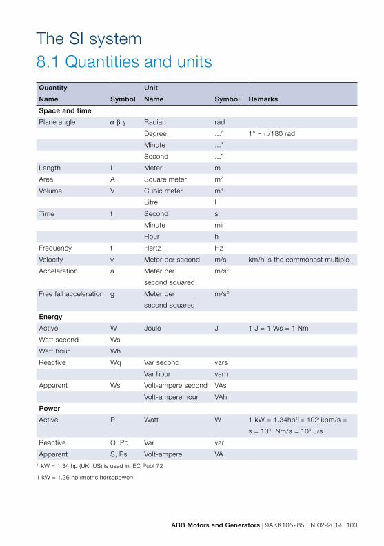
ABB Motors and Generators | 9AKK105285 EN 02-2014 103
Quantity Unit
Name Symbol Name Symbol Remarks
Space and time
Plane angle αβγ Radian rad
Degree ...° 1° = π/180 rad
Minute ...’
Second ...”
Length I Meter m
Area A Square meter m2
Volume V Cubic meter m3
Litre l
Time t Second s
Minute min
Hour h
Frequency f Hertz Hz
Velocity v Meter per second m/s km/h is the commonest multiple
Acceleration a Meter per
second squared
m/s2
Free fall acceleration g Meter per
second squared
m/s2
Energy
Active W Joule J 1 J = 1 Ws = 1 Nm
Watt second Ws
Watt hour Wh
Reactive Wq Var second vars
Var hour varh
Apparent Ws Volt-ampere second VAs
Volt-ampere hour VAh
Power
Active P Watt W 1 kW = 1.34hp1) = 102 kpm/s =
s = 103 Nm/s = 103 J/s
Reactive Q, Pq Var var
Apparent S, Ps Volt-ampere VA1) kW = 1.34 hp (UK, US) is used in IEC Publ 72
1 kW = 1.36 hp (metric horsepower)
8.1 Quantities and unitsThe SI system

104 9AKK105285 EN 02-2014 | ABB Motors and Generators
Quantity Unit
Name Symbol Name Symbol Remarks
Mechanical
Mass m Kilogram kg
Tonne t
Density ρ Kilogram per
cubic meter
kg/m3
Force F Newton N 1 N = 0.105 kp
Moment of force M Newton-meter Nm 1 Nm = 0.105 kpm = 1 Ws
Moment of inertia J Kilogram-meter kgm2 J = G x D2
Pressure p Pascal Pa 1 Pa = 1 N/m2
Newton per
square meter
N/m2 1 N/m2 = 0.102 kp/m2 = 10-5 bar
Bar bar 1 bar = 105 N/m2
Heat
Thermodynamic
temperature
T, θ Kelvin K Old name: absolute
temperature
Celsius temperature ϑ, t Degree Celsius °C 0 °C = 273.15 K
Temperature ΔT, Δϑ Kelvin K The interval 1 K is identical to
difference the interval 1 °C
Degree Celsius °C
Thermal energy Q Joule J
Electricity
Electric potential V Volt V 1 V = 1 W/A
Electric voltage U Volt V
Electric current I Ampere A
Capacitance C Farad F 1 F = 1 C/V
Reactance X Ohm Ω
Resistance R Ohm Ω 1 Ω = 1 V/A
Impedance Z Ohm Ω Z = √ R2+X2
8.2 PrefixesMultiples of SI units are indicated by the following prefixes. The use of prefixes in brackets should be avoided because they not generally well-known.
103 kilo k(102) (hecto) (h)(101) (deca) (da)(10-1) (deci) (d)
(10-2) (centi) (c)10-3 milli m10-6 micro μ10-9 nano n
10-12 pico p10-15 femto f10-18 atto a

ABB Motors and Generators | 9AKK105285 EN 02-2014 105
The units generally used for technical applications are SI units.
However, other units may be encountered in descriptions, drawings, etc., especially where the inch system is involved.
Note that the US gallon and the UK gallon are not the same. To avoid confusion it is advisable to use the abbreviation ‘US’ or ‘UK’ after the unit. The following table lists some of most commonly needed conversion factors.
Length1 nm = 1.852 km 1 km = 0.540 nm1 mile = 1.609344 km 1 km = 0.621 mile1 yd = 0.9144 m 1 m = 1.09 yd1 ft = 0.3048 m 1 m = 3.28 ft1 in = 25.4 mm 1 mm = 0.039 inVelocity1 knot = 1.852 km/h 1 km/h = 0.540 knot1 m/s = 3.6 km/h 1 km/h = 0.278 m/s1 mile/h = 1.61 km/h 1 km/h = 0.622 mile/hArea1 acre = 0.405 ha 1 ha = 2.471 acre1 ft2 = 0.0929 m2 1 m2 = 10.8 ft2
1 in2 = 6.45 cm2 1 cm2 = 0.155 in2
Volume1ft3 = 0.0283 m3 1 m3 = 36.3 ft3
1 in3 = 16.4 cm3 1 cm3 = 0.0610 in3
1 gallon (UK) = 4.55 l 1 l = 0.220 gallon (UK)1 gallon (US) =3.79 l 1 l = 0.264 gallon (US)1 pint = 0.568 l 1 l = 1.76 pintFlow1 m3/h = 0.278 x 10⁻³ m3/s 1 m3/s = 3600 m3/h1 cfm = 0.472 x 10⁻³ m3/s 1 m3/s = 2120 cfmMass1 lb = 0.454 kg 1 kg = 2.20 lb1 oz = 28.3 g 1 g = 0.0352 oz
Force1 kp = 9.80665 N 1 N = 0.105 kp1 lbf = 4.45 N 1 N = 0.225 lbfPressure1 mm vp = 9.81 Pa 1 Pa = 0.102 mm vp1 kp/cm2 = 98.0665 kPa 1 kPa = 0.0102 kp/cm2
1 kp/cm2 = 0.980665 bar 1 bar = 1.02 kp/m2
1 atm = 101.325 kPa 1 kPa = 0.00987 atm1 lbf/in2 = 6.89 kPa 1 kPa = 0.145 lbf/in2
Energy1 kpm = 9.80665 J 1 J = 0.102 kpm1 cal = 4.1868 J 1 J = 0.239 cal1 kWh = 3.6 MJ 1 MJ = 0.278 kWhPower1 hp = 0.736 kW 1 kW = 1.36 hp1 hp (UK, US) = 0.746 kW 1 kW = 1.34 hp (UK, US)1 kcal/h = 1.16 W 1 W = 0.860 kcal/hTemperature0 °C = 32 °F°C = 5/9 (°F - 32)0 °F = -17.8 °C°F = 9/5 (°C + 32)
Comparison table for temperatures°F °C0 -17.810 -12.220 -6.730 -1.132 040 4.4
Comparison table for temperatures°F °C50 9.960 15.570 21.080 23.690 32.1100 37.8
8.3 Conversion factors

106 9AKK105285 EN 02-2014 | ABB Motors and Generators

ABB Motors and Generators | 9AKK105285 EN 02-2014 107
9. Ordering
9. Ordering 1089.1 Selecting a motor 1099.2 Online tools 1119.2.1 Optimizer 1119.2.2 DriveSize and MotSize 1129.3 Loading (kW) 1129.4 Speed 1139.5 Starting the motor 1139.6 Operating environment 1149.7 Ordering and order check list 114
108 9AKK105285 EN 02-2014 | ABB Motors and Generators
OrderingABB’s sales force plays a key role in defining the right product with the customer and communicating the customer order towards production units. The order specifications are initially defined at the offering phase, but will often be more accurate, or even changed, when placing the actual order. For the production units to deliver motors according to the customers’ specifications and needs, it is important that all information stated in the order is correct, and no relevant information is missing.
This chapter explains how to select a motor and what tools there are to help in selection. Requirements for making a valid order are also introduced.
ABB Motors and Generators | 9AKK105285 EN 02-2014 109
Ordering9.1 Selecting a motorThere are three fundamental variables to consider when selecting a motor:
− electricity supply to which the motor will be connected − type of enclosure or housing of the motor (IP class) − starting method (see Electrical design)
Network voltage and frequency vary between regions and countries of the world. What is more, industries and applications may require voltages that are unrelated to the country where the motor is used or purchased, whereas frequency is usually region-specific. The table presents network voltages and frequencies in a number of selected countries and regions of the world. The voltages shown here are the most commonly available; be sure to verify the exact required voltage per each customer case.

110 9AKK105285 EN 02-2014 | ABB Motors and Generators
Area/country
Voltage
V
Frequency
Hz
Europe
EU 220, 230, 400, 500, 690 50
Russia 220, 380 50
Africa
Africa, majority of 220, 380, 400, 415 50
South Africa 220, 230, 380, 400, 500 50
Middle East
Israel 220,230, 280, 400, 415 50
Saudi Arabia 220, 230, 380, 400, 440 50, 60
India 220, 230, 400, 415 50
North America
Canada 230, 460, 575, 600 60
United States 230, 460, 480 60
Mexico 220, 480 60
Central America
Cuba 220, 440 60
Costa Rica 240, 440 60
South America
Brazil 220, 380, 440 60
Chile 220, 380, 400, 500 50, 60
Argentina 220, 380, 440 50
Northeast Asia
China 380, 400 50
Japan 200, 220, 400, 440 50, 60
South Korea 220, 380, 440 60
Southeast Asia
Philippines 115, 380, 440 60
Malaysia 240, 415 50
Indonesia 220, 380, 400 50
Oceania
New Zeeland 230, 240, 400, 415 50
Australia 230, 240, 415, 440 50
Table 9.1. World network voltages and frequencies
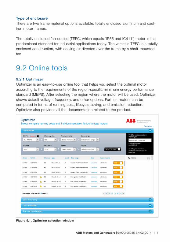
ABB Motors and Generators | 9AKK105285 EN 02-2014 111
Type of enclosureThere are two frame material options available: totally enclosed aluminum and cast-iron motor frames.
The totally enclosed fan-cooled (TEFC, which equals ‘IP55 and IC411’) motor is the predominant standard for industrial applications today. The versatile TEFC is a totally enclosed construction, with cooling air directed over the frame by a shaft-mounted fan.
9.2 Online tools9.2.1 OptimizerOptimizer is an easy-to-use online tool that helps you select the optimal motor according to the requirements of the region-specific minimum energy performance standard (MEPS). After selecting the region where the motor will be used, Optimizer shows default voltage, frequency, and other options. Further, motors can be compared in terms of running cost, lifecycle saving, and emission reduction. Optimizer also provides all the documentation related to the product.
Figure 9.1. Optimizer selection window
Cost of runningCost of running
Find motorsFind motors
DocumentationDocumentation
Summary and exportSummary and export
Optimizer
Contact usSelect, compare running costs and find documentation for low voltage motors
MEPS [Required] Efficiency class Frame material Motor range
Voltage Frequency Speed Output
MEPS [Required] Efficiency class Frame material Motor range
Voltage Frequency Speed Output
Find by producy code ormotor type
e.g. M3BP280SMA / 3GBP282210
Input the product code to quickly find the motor you are looking for.
3 4 5 6 7 > 2 1 Displaying 1-100 out of 812 motors.
?
EU - MEPS IE2 Select frame ma Select motor range
400V 50Hz Select poles Select output (kW)
Product code / motor type
RESET FILTERS X
Output Volt./Hz Eff. class Type Speed Motor range Data Frame material
0.75kW 400V 50Hz IE2 M2AA 80 B 2 2 General Performance Motors View data Aluminum
My motors
ADD
0.75kW 400V 50Hz IE2 M2AA 80 D 4 4 General Performance Motors View data Aluminum ADD
0.75kW 400V 50Hz IE2 M2AA 90 LB 6 6 General Performance Motors View data Aluminum ADD
0.75kW 400V 50Hz IE2 M2AAD 80 A 2 2 Dust Ignition Proof Motors View data Aluminum ADD
0.75kW 400V 50Hz IE2 M2AAD 80 B 2 2 Dust Ignition Proof Motors View data Aluminum ADD
0.75kW 400V 50Hz IE2 M2AAD 80 D 4 4 Dust Ignition Proof Motors View data Aluminum ADD

112 9AKK105285 EN 02-2014 | ABB Motors and Generators
9.3 Loading (kW)Loading of the motor is determined by the equipment driven and the torque available on the shaft.
IEC electric motors have standard outputs per frame size. See Standards, Output power and frame size correlation for detailed information about how the standard determines power and frame size combinations.
9.2.2 DriveSize and MotSizeDriveSize and MotSize are software programs for selecting and dimensioning an optimal low voltage motor, frequency converter and transformer, particularly in cases where motor requirements fall outside of those presented in the motor catalog. DriveSize and MotSize can also be used to compute network harmonics and to print out dimensioning information. The programs contain current versions of our motor and frequency converter catalogs. Both tools are downloadable on ABB’s web pages.
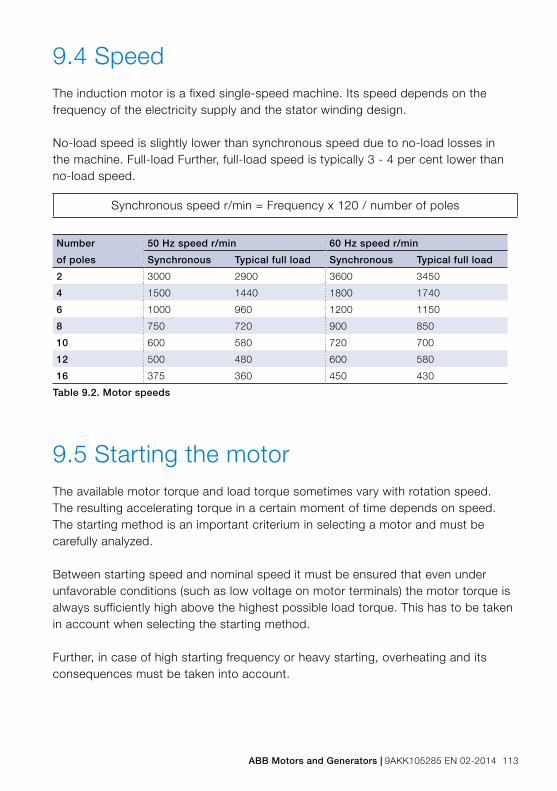
ABB Motors and Generators | 9AKK105285 EN 02-2014 113
9.4 SpeedThe induction motor is a fixed single-speed machine. Its speed depends on the frequency of the electricity supply and the stator winding design.
No-load speed is slightly lower than synchronous speed due to no-load losses in the machine. Full-load Further, full-load speed is typically 3 - 4 per cent lower than no-load speed.
Synchronous speed r/min = Frequency x 120 / number of poles
Number
of poles
50 Hz speed r/min 60 Hz speed r/min
Synchronous Typical full load Synchronous Typical full load
2 3000 2900 3600 3450
4 1500 1440 1800 1740
6 1000 960 1200 1150
8 750 720 900 850
10 600 580 720 700
12 500 480 600 580
16 375 360 450 430
Table 9.2. Motor speeds
9.5 Starting the motorThe available motor torque and load torque sometimes vary with rotation speed. The resulting accelerating torque in a certain moment of time depends on speed. The starting method is an important criterium in selecting a motor and must be carefully analyzed.
Between starting speed and nominal speed it must be ensured that even under unfavorable conditions (such as low voltage on motor terminals) the motor torque is always sufficiently high above the highest possible load torque. This has to be taken in account when selecting the starting method.
Further, in case of high starting frequency or heavy starting, overheating and its consequences must be taken into account.

114 9AKK105285 EN 02-2014 | ABB Motors and Generators
9.6 Operating environmentThe operating environment of the motor is another important factor to consider when ordering, because ambient temperature, humidity, and altitude can all affect performance.
Having an IP55 motor does not mean that it will remain tight in any outdoor operating conditions. The application where the motor is used, mounting position and actual exposure to external factors need to be taken into account. For example, ambient temperatures above 40 °C or altitudes above 1000 m mean reduced loadability. Similarly, mounting on the ceiling means that non-standard drain holes need to be ordered.
All metals corrode with varying intensity under the influence of chemicals and humidity. For example, pure aluminum and most of its alloys, without special surface treatment, are very sensitive to salt water. On the other hand, cast iron as such is durable against many chemicals except for the machined parts like drilling holes or centering borders. Selecting the right surface treatment will help lengthen the life of the motor and reduce the need for maintenance. See Mechanical Design, Surface treatment for further information.
9.7 Ordering and order check listThe following things must be known when placing a customer order:
− motor type, supply voltage and frequency, and product code − mounting position − variant codes for options in motor design or appliances, such as: − cable flanges and other connection parts, unless standard − special insulation and insulated bearings, unless standard − duty type and ambient conditions − rating values − number of motors ordered − price, delivery time, and delivery address − quotation reference number
Order management system (OMS) is a complete order management and logistics system for low and high voltage motors, and it is used by ABB’s production units, It is often possible to deliver special features if they are based on the actual offer. If there is no variant code for a desired feature, you may check the availability, price and delivery time of the said feature through ABB sales personnel.

ABB Motors and Generators | 9AKK105285 EN 02-2014 115
10. Variable speed drives
10. Variable speed drives 11610.1 Types of drives 11710.2 Pulse width modulation (PWM) 11810.3 Dimensioning the drive 11810.4 Loadability (torque) 12010.4.1 Improving loadability 12110.5 Insulation level 12210.6 Earthing 12210.7 Operation at maximum speed 12310.8 Balancing 12510.9 Critical speeds 12510.10 Shaft seals 12510.11 Low speed operation 126

116 9AKK105285 EN 02-2014 | ABB Motors and Generators
Variable speed drivesSquirrel cage induction motors offer excellent availability, reliability and efficiency. However, they have two weaknesses: high starting current and lack of smooth speed control over a wide speed range. A motor supplied by a variable speed drive (VSD) - also called frequency converter – usually solves both problems. A VSD-driven motor can be started softly with low starting current, and speed can be controlled and adjusted smoothly according to the application over a wide speed range.
The benefits of VSDs are widely recognized: optimal speed and control accuracy; reduced maintenance thanks to lower running speeds; higher production quality. Accordingly, there is a large number of VSD applications on the market, and approximately one half of new motor installations include a VSD.

ABB Motors and Generators | 9AKK105285 EN 02-2014 117
Variable speed drives10.1 Types of drivesVariable speed drives are power electronic devices which convert fixed input voltage, AC or DC, into variable voltage and frequency on the output side. The application determines whether a direct or indirect converter is used.
ConverterA converter is a variable speed drive converting fixed AC supply to variable voltage and frequency. It consists of four main parts: rectifier, DC circuit, inverter unit, and control unit. Converters are connected to an AC supply.
InverterAn inverter is a variable speed drive converting fixed DC supply to variable AC voltage and frequency. It consists of two main parts: inverter unit and control unit. Inverters are connected to a DC source and are sometimes called common DC bus drives.
Direct converterDirect converters such as cycloconverters and matrix converters change the input voltage and frequency directly to output without intermediate DC links. Cycloconverters are used in high-power (megawatt-level) applications and at low frequencies.
Indirect convertersIndirect converters are either current source or voltage source converters.In a voltage source converter (VSC), the most common converter topology in low voltage applications, the intermediate link acts as a DC voltage source, and its output consists of controlled voltage pulses at continuously varying frequency. The pulses are fed to the different phases of a three-phase system. This enables stepless speed control of the motor.
In a current source converter (CSC), the DC link acts as a DC current source, and its output is a current pulse or a current pulse sequence.

118 9AKK105285 EN 02-2014 | ABB Motors and Generators
10.2 Pulse width modulation (PWM)ABB low voltage VSC variable speed drives use pulse width modulation (PWM) with variable switching frequency, which best meets the majority of requirements. The used control method, such as direct torque control (DTC), vector control, or scalar control, depends on the product and application.
In a PWM drive, the rectifier converts the input line power, which has a nominally fixed voltage and frequency, into fixed DC voltage. This fixed DC voltage is then filtered to reduce the ripple voltage resulting from the rectification of the AC line. The inverter then changes the fixed DC voltage into AC output power with adjustable voltage and frequency.
10.3 Dimensioning the drive
Figure 10.1 The working principle of a VSD-driven motor
DriveSize, a complete dimensioning tool for drives and motors, can be downloaded from www.abb.com/motors&generators. The following is a brief explanation about motor and converter selection with the DriveSize software.
Motor selectionThe actual load torque should be below the reference loadability curve (or load capacity curve) of the selected motor and converter combination (see Figure 10.2 in Section 10.4). However, if the motor operation is not continuous in all duty points of the speed range, the load curve may exceed the reference curve. In this case, special dimensioning is required.
ABB Motors and Generators | 9AKK105285 EN 02-2014 119
Further, the maximum torque of the motor must be at least 40 percent higher than the load torque at any frequency, and the maximum permissible speed of the motor must not be exceeded.
Motor designConverters with different working principles, modulation patterns and switching frequencies give different performances for the same motor. As performance and behavior are also dependent on motor design and construction, motors of the same size and output power but different design may behave very differently with the same converter. Therefore, the selection and dimensioning instructions are product-specific.
Converter selectionThe converter should be selected according to the nominal power PN and rated current of the motor. Sufficient current margin should be reserved for controlling and managing dynamic situations.

120 9AKK105285 EN 02-2014 | ABB Motors and Generators
10.4 Loadability (torque)Both theoretical calculations and laboratory tests show that the continuous maximum load (torque) of a converter-driven motor mainly depends on the modulation pattern and switching frequency of the converter, but also on the design of the motor. The graph below is a guideline for motor selection.
These curves present the maximum continuous load torque of the motor as a function of frequency (speed) to match the temperature rise of the rated sinusoidal voltage supply at nominal frequency and full rated load.
ABB motors are usually designed to fall within temperature rise class B. Process performance motors (unlike motors for hazardous areas), for example, can in such cases be dimensioned either according to temperature rise class B curve, or temperature rise class F curve, which provides higher loadability. If the product catalog indicates that class F temperature rise applies on sinusoidal supply, in frequency converter use the motor can only be dimensioned according to the temperature rise class B curve.
The following ABB motors can be used with frequency converters: − Process performance motors (designed for demanding industrial applications) − General performance aluminum and cast iron motors (for general applications) − Motors for explosive atmospheres: flameproof, non-sparking, and dust ignition
protection motors − Note: special motors such as synchronous reluctance motors, high speed motors
and permanent magnet motors are always VSD-driven. Some of these require motor-type specific drives software.
Figure 10.2. Reference curve for motor loadability with ABB’s frequency converters (Process performance motors)

ABB Motors and Generators | 9AKK105285 EN 02-2014 121
10.4.1 Improving loadabilityThe output torque of frequency-converter-driven motors is usually slightly reduced because of heating caused by harmonics and a decrease in cooling at reduced voltage and lower frequencies. However, the loadability of the motor can be improved with the following means.
More effective coolingMore effective cooling is achieved by mounting a separate constant-speed fan, which is especially beneficial at low speeds. Selecting optimal fan motor speed and fan design to deliver a stronger cooling effect than with a standard motor at nominal speed will give an improved cooling effect over the entire speed range. Liquid cooling (water-cooled motors) is another very effective cooling method. In very demanding circumstances the bearing end shields must also be cooled, for example by adding cooling disks on the shaft.
FilteringFiltering the converter output voltage reduces the harmonic content of the motor’s voltage and current and therefore reduces the generation of additional losses in the motor. This reduces the need for derating. Full power of the drive and the speed range of the motor must be taken into account when dimensioning filters (additional reactance). However, filters may limit the maximum torque and speed of the motor. Filters also reduce electromagnetic noise, EMC, and voltage peaks.

122 9AKK105285 EN 02-2014 | ABB Motors and Generators
10.5 Insulation levelIn a frequency converter the output voltage (or current) most often is a voltage (current) pulse or a pattern of pulses. Depending on the type of power components and the design of the power circuit, considerable overshoot may develop at the leading edge of a voltage pulse. This is why winding insulation level must always be checked in product-specific guidelines. The basic rules for standard applications are:
− If the nominal voltage of the supply network is max. 500 V, no insulation strengthening is required for standard ABB induction motors.
− If the nominal network voltage is from 501 up to 600 V, special motor insulation or dU/dt-filters are required.
− If the nominal network voltage is from 601 up to 690 V, special motor insulation and dU/dt-filters are required.
− If the nominal network voltage is from 601 up to 690 V and the motor’s supply cables are longer than 150 meters, special motor insulation is required.
Exact product specific guidelines can be found in ABB product catalogs.
10.6 EarthingIn converter usage, special attention must be paid to earthing arrangements to ensure:
− Proper action of all protective devices and relays for general safety − Minimal or acceptable electromagnetic interference − An acceptable level of bearing voltages to avoid bearing currents and bearing
failures
ABB recommends using symmetrical shielded cables with cable glands providing a 360-degree connection (so-called EMC glands).

ABB Motors and Generators | 9AKK105285 EN 02-2014 123
10.7 Operation at maximum speedIn converter usage, the actual speed of the motor may deviate considerably from its nominal speed. In operation at higher speeds, the maximum permissible speed of the motor type and the critical speed of the entire equipment must not be exceeded.
When the motor is run at higher than nominal speed, maximum torque and bearing construction should also be checked. Notice that if a standard fan is used, also friction and cooling losses as well as the noise level will increase.
Maximum torqueIn the field weakening area the voltage of the motor is constant, but motor flux and capability to produce torque reduce approximately in square of the frequency after the field weakening point (the point after which output voltage remains constant even though the output frequency increases). At the highest speed point, or at any other duty point in the field weakening area, the maximum (breakdown) torque must at least 40 percent higher than the load than the load torque to avoid excessive rotor heating.
If filters or additional reactances are used between the converter and motor, the voltage drop from the fundamental voltage with full load current must be taken into account.
Bearing constructionThere is a limit to the speed at which rolling bearings can be operated. Bearing type and size, design, load, lubrication and cooling conditions as well as cage design, accuracy and internal clearance all influence the permissible maximum speed.
LubricationIn general, the lubrication intervals are affected by the operating and ambient temperatures with respect to the lubricant and bearing component. Changing the bearings and/or lubricant may enable higher speeds. However, if this is done, the correct combination should be verified with ABB.
Table 10.1 Maximum speeds of Process performance motors
Frame size Speed r/min
2-pole motor4-pole motor
71 - 80 6000 4500
90 - 100 6000 6000
112 - 200 4500 4500
225 - 250 3600 3600
280 3600 2600
315 3600 2300
355 3600 2000
400 3600 1800
450 3000 1800
124 9AKK105285 EN 02-2014 | ABB Motors and Generators
The sheer strength of the lubricant is determined by its base oil viscosity and thickener, which in turn determines the permissible operating speed for the particular bearing. The maximum speed can be increased by using high speed greases or oil lubrication. Very accurate relubrication with small quantities also reduces bearing friction and heat generation.
Fan noiseFan noise increases with the speed of the motor and usually becomes dominant at 50 Hz for 2- and 4-pole motors. If the speed further increases, the noise level will also increase. The noise level increase can be calculated approximately with the following formula:
ΔLsp = 60 x log ——n2
n1 dB(A)
where Δ Lsp = increase of the sound pressure level when speed changes from n1 to n2.
Fan noise is typically ‘white noise’, which means that it contains all frequencies within the audible frequency range.
Fan noise can be reduced by either: − Replacing the fan (and fan cover) with a reduced outer diameter fan − Using a unidirectional fan − Fitting a silencer

ABB Motors and Generators | 9AKK105285 EN 02-2014 125
10.8 BalancingThe balancing accuracy and mechanical strength of all rotating parts should be checked if the permissible maximum speed of the motor is exceeded. All other parts mounted on the motor shaft, such as coupling halves and pulleys must also be carefully balanced.
10.9 Critical speedsThe first critical speed of the whole drive system, or of its components should not be exceeded, and a safety margin of 25 percent should be allowed.Also supercritical drive systems can be used, but those must be dimensioned on case-by-case basis.
10.10 Shaft sealsAll rubbing shaft seals (V-rings, oil seals, etc.) have a recommended maximum speed limit. If this is below the proposed high-speed operation, non-rubbing labyrinth seals should be used.

126 9AKK105285 EN 02-2014 | ABB Motors and Generators
10.11 Low speed operationLubricationAt very low speeds, the motor’s ventilation fan loses its cooling capacity. If the operational temperature of the motor bearings is ≥ 80 °C, (check by measuring the surface temperature of the bearing end-shields), shorter relubrication intervals or special grease (Extreme Pressure (EP) grease or high temperature lubricant) should be used.
The re-lubrication interval should be halved for each 15 °C increase in the bearing temperature above + 70 °C.
Cooling capacity of a fanThe air flow and cooling capacity depends on the fan speed. A separate constant-speed fan can be used to increase cooling capacity and motor loadability at low speeds. As the internal cooling is not affected by a separate outer fan, a small reduction in loadability is still necessary at very low speeds.
Electromagnetic noiseThe harmonic components of frequency converter voltage increase the magnetic noise from the motor. The frequency range of these magnetic force waves can cause structural resonance in the motor, especially in steel-framed ones.
Magnetic noise can be reduced by: − Increasing the switching frequency, giving higher order harmonics and lower
amplitudes which are less disturbing to the human ear. On the other hand, setting to a high switching frequency may reduce the output current of the drive.
− Filtering the harmonic components at the converter output filter or in additional reactances
− Motor silencer
More information on noise reduction can be found in Chapter Noise.

ABB Motors and Generators | 9AKK105285 EN 02-2014 127

9AK
K10
5285
EN
02-
2014www.abb.com/motors&generators
Contact us
We reserve the right to make technical changes or modify the contents of this document without prior notice. With regard to purchase orders, the agreed particulars shall prevail. ABB does not accept any responsibility what so ever for potential errors or possible lack of information in this document.
We reserve all rights in this document and in the subject matter and illustrations contained herein. Any reproduction, disclosure to third parties or utilization of its contents – in whole or in parts – is forbidden without prior written consent of ABB.
© Copyright 2014 ABB. All rights reserved.


