• What is reactive energy and why it is necessary to compensate it • Automatic capacitor banks type QA1, a compact and cost effective solution • Fixed type capacitor banks QAF • High power automatic capacitor banks type QA2 • Compensation in the presence of harmonic currents • Automatic banks type QAM with reinforced capacitors • Automatic banks type QAR with anti-harmonic protection reactors for mains heavily polluted with harmonic currents • Harmonic Filters • Ultra-fast compensation • Individual reactive compensation for transformers • Individual reactive compensation for electric motors • Protection breakers and connecting cables for capacitor banks
3
What is reactive energy and why it is necessary to compensate it Reactive energy is consumed by the receivers, such as transformers, motors, ballasts, fluorescent tubes, etc. and it is charged as well as the active energy by the electric power suppliers. Reactive energy (Er) is expressed in kilovar hours (kVARh). It is used in particular to create the magnetic field in the windings of motors, transformers, etc. Without the magnetic field their operation would be impossible. Q is the reactive power (kvar) which corresponds to this energy. Active energy (Ea) is expressed in kilowatt hours (kWh). It can be used, after processing by the receiver, in the form of work or heat. Active power P[kW] corresponds to this energy. The apparent power is by definition S = √ (P)2+ (Q)2 [kVA] The tangent tan φ is the ratio φ = Er / Ea and the power factor or cos φ is the ratio cos φ = P / S. The energy metering devices record active and reactive energy consumption’ The electricity suppliers generally show the term tan φ or cos φ on their bill. Unlike the cos φ, it is easy to see that the value of tan φ should be as small as possible in order to have the least reactive energy consumption. A good power factor is cos φ high (close to 1) or tan φ low (close to 0). Reactive power compensation gives you the following benefits: • savings on electrical equipment, a decrease of the power demand • an increase in available power of the supply transformer • lower voltage drops and Watt losses in cables • savings on electricity bills by eliminating reactive energy consumption • the reduction of subscribed power kVA [if available] To compensate for reactive power, it is necessary to provide reactive power by installing compensation equipment instead of taking it from the main distribution. If the value of reactive power to compensate it is small compared to the total apparent power of all the loads (Qc / St <15%), we can choose fixed type compensation equipment. If this value is higher (Qc / St> 15%) it is advisable to choose an automatic compensation equipment.
4
Compact, cost effective solution automatic capacitor banks type QA1 Application Central reactive power compensation in mains without or with little harmonic load Sh/St<15% Sh = total apparent power of harmonics producing loads Equipment
Cylindrical aluminum case, low-loss, self healing with overpressure protection, dry, gas or resin impregnated, long life (>130.000h) capacitors;
Special capacitor contactors with leading inrush current limiting resistances; Highly reliable automatic power factor regulator with voltage, current , PF and current THD
displays, alarms for overvoltage, over and under compensation; Fuse switch disconnectors with NH fuses or MCB (option) for groups of capacitors; Forced ventilation for higher compensation power; Sturdy wall mounted cabinet; Compensation powers up to 200 kvar;
Standards EN 61921, EN 60439-1, EN 60831-1 Rated voltage 230 – 690V, 50Hz Installation Indoor, outdoor on demand, up to 2000m above see level Protection IP21 or IP54 on demand Basic types
Options Other power, number of steps: maximum flexibility, we adapt to your requests! Input general switch/ input general breaker
5
Automatic Bank Un: 3x400V + N, 50Hz Qn: 50 kvar (2 x 6.25 + 12.5 + 25 kvar) Input: 125A/ 10 kA MCB
Automatic bank Un: 3x400V + N, 50Hz Qn: 195 kvar (5 +10 + 9 x 20 kvar) Input: 60 mm bus bars system (30x10mm2 copper bars) Protection: 4 x 125A bus-mounting
NH fuse switch disconnectors
Automatic Bank Un: 3x400V + N, 50Hz Qn: 25 kvar (5 + 2 x 10 kvar) Input: 63A panel- mounting
NH fuse switch disconnector
6
Fixed type capacitor banks QAF
Application Local (load) reactive power compensation in mains without or with little harmonic loads. Equipment
Cylindrical aluminum case, low-loss, self healing with overpressure protection, dry, gas or resin impregnated, long life (>130.000h) three phase capacitors;
Fuse switch disconnectors with NH fuses or MCB (option); Green lamp on door for POWER ON signaling Sturdy wall mounted cabinet; Compensation powers up to 50 kvar
Standards EN 61921, EN 60439-1, EN 60831-1 Rated voltage 230 – 690V, 50Hz Installation Indoor, outdoor on demand up to 2000m above see level Protection IP21 or IP54 on demand
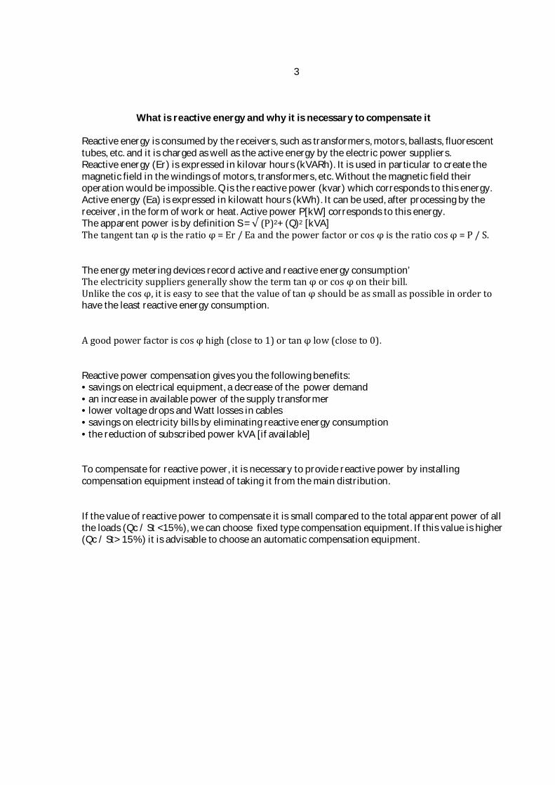
Fixed bank Un: 3x400V, 50Hz Qn: 15 kvar Input: 63A/ 10kA MCB
One step automatic bank Un: 3x400V, 50Hz Qn: 1x20 kvar Protection: 63A/ 10kA MCB
7
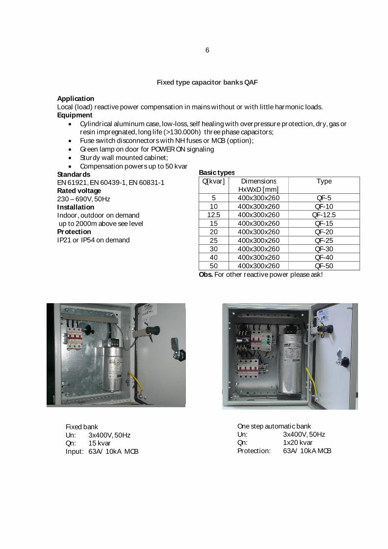
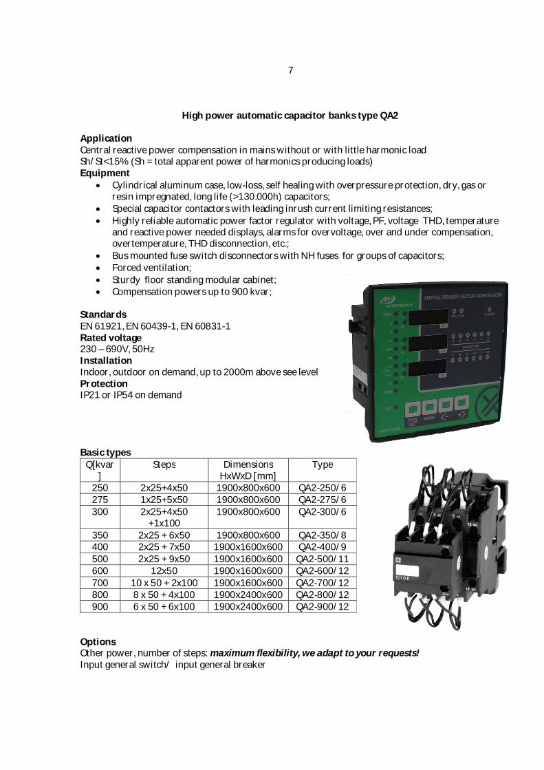
High power automatic capacitor banks type QA2 Application Central reactive power compensation in mains without or with little harmonic load Sh/St<15% (Sh = total apparent power of harmonics producing loads) Equipment
Cylindrical aluminum case, low-loss, self healing with overpressure protection, dry, gas or resin impregnated, long life (>130.000h) capacitors;
Special capacitor contactors with leading inrush current limiting resistances; Highly reliable automatic power factor regulator with voltage, PF, voltage THD, temperature
and reactive power needed displays, alarms for overvoltage, over and under compensation, overtemperature, THD disconnection, etc.;
Bus mounted fuse switch disconnectors with NH fuses for groups of capacitors; Forced ventilation; Sturdy floor standing modular cabinet; Compensation powers up to 900 kvar;
Standards EN 61921, EN 60439-1, EN 60831-1 Rated voltage 230 – 690V, 50Hz Installation Indoor, outdoor on demand, up to 2000m above see level Protection IP21 or IP54 on demand Basic types
Options Other power, number of steps: maximum flexibility, we adapt to your requests! Input general switch/ input general breaker
8
Compensation in the presence of current harmonics
It is well known that some electrical loads (electronic converters such as the inverter, rectifier, variable speed motors, welding machines, arc furnaces, fluorescent tubes) inject harmonic currents in mains that overload the capacitors. Harmonics can cause destruction of capacitors and generate resonances on the network or cause malfunctions of equipment. For centralized compensation in power networks with an average degree of harmonic pollution (15< Sh/St <25), we can use capacitors with superior rated voltage of 440V or 480V. These capacitors endure better the effect of harmonic overload. But we must verify by careful calculation that the apparence of resonance in the electric network it is not possible! If the resonance is possible or the calculation shows that the harmonic overload or the degree of deformation of network voltage is too high, the solution is to use capacitor banks with anti-resonance protection reactors.
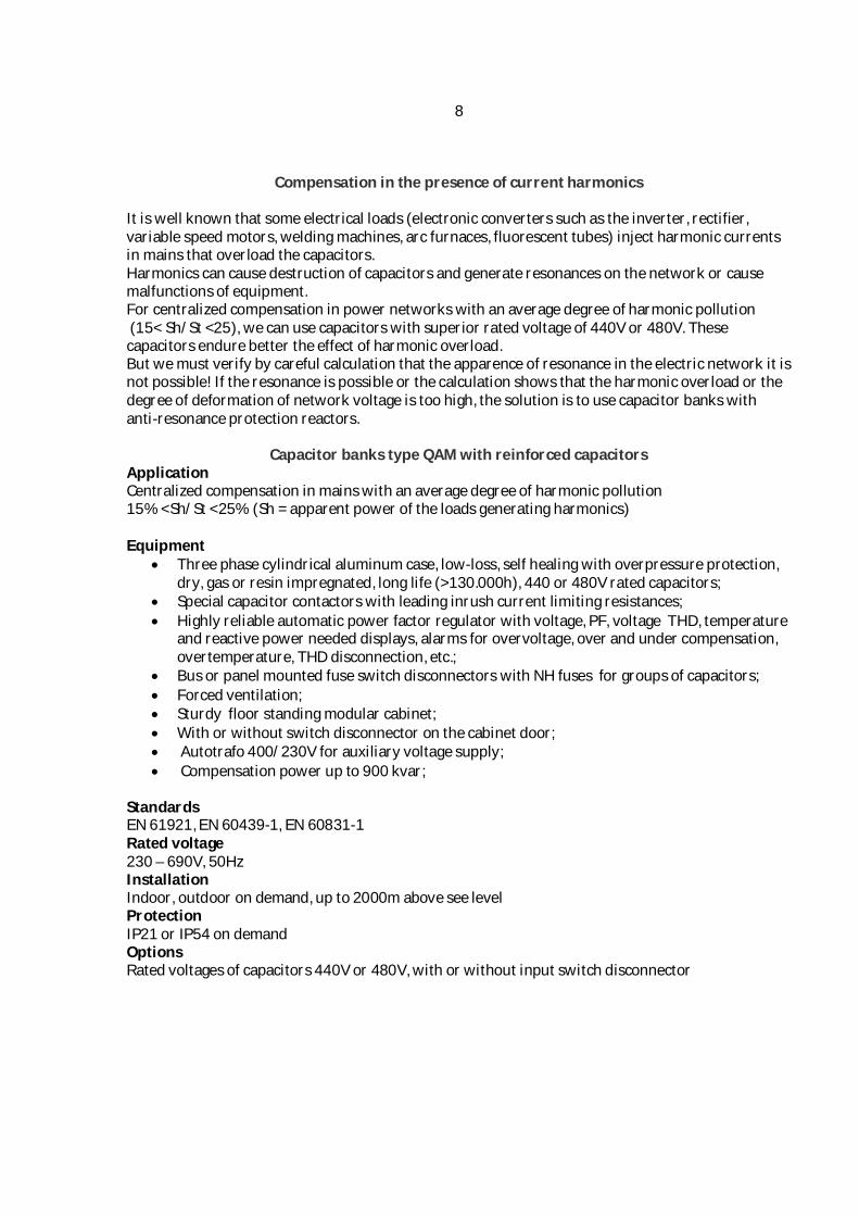
Capacitor banks type QAM with reinforced capacitors
Application Centralized compensation in mains with an average degree of harmonic pollution 15% <Sh/St <25% (Sh = apparent power of the loads generating harmonics) Equipment
Three phase cylindrical aluminum case, low-loss, self healing with overpressure protection, dry, gas or resin impregnated, long life (>130.000h), 440 or 480V rated capacitors;
Special capacitor contactors with leading inrush current limiting resistances; Highly reliable automatic power factor regulator with voltage, PF, voltage THD, temperature
and reactive power needed displays, alarms for overvoltage, over and under compensation, overtemperature, THD disconnection, etc.;
Bus or panel mounted fuse switch disconnectors with NH fuses for groups of capacitors; Forced ventilation; Sturdy floor standing modular cabinet; With or without switch disconnector on the cabinet door; Autotrafo 400/230V for auxiliary voltage supply; Compensation power up to 900 kvar;
Standards EN 61921, EN 60439-1, EN 60831-1 Rated voltage 230 – 690V, 50Hz Installation Indoor, outdoor on demand, up to 2000m above see level Protection IP21 or IP54 on demand Options Rated voltages of capacitors 440V or 480V, with or without input switch disconnector
9
Insulated neutral (IT systems)
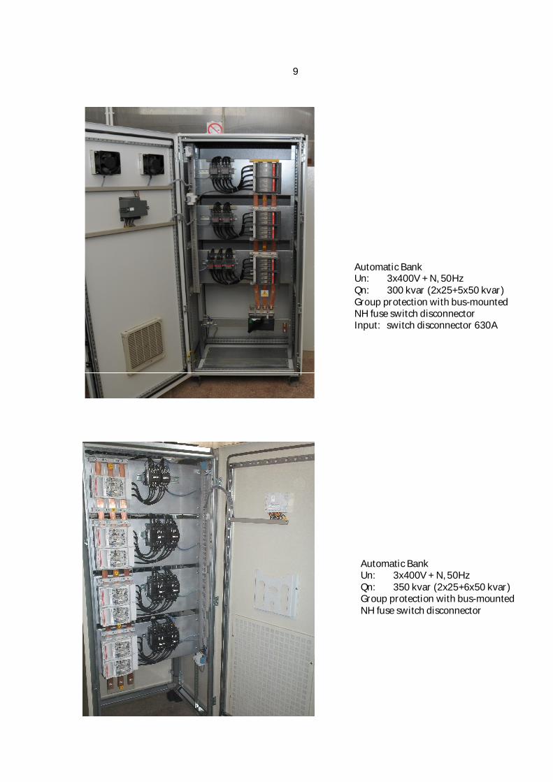
Automatic Bank Un: 3x400V + N, 50Hz Qn: 300 kvar (2x25+5x50 kvar) Group protection with bus-mounted NH fuse switch disconnector Input: switch disconnector 630A
Automatic Bank Un: 3x400V + N, 50Hz Qn: 350 kvar (2x25+6x50 kvar) Group protection with bus-mounted NH fuse switch disconnector
10
Reactor protected automatic capacitor banks type QAR
Application Central reactive power compensation in mains with harmonic loads. 25% <Sh/St <50% (Sh = apparent power of the loads generating harmonics) Equipment
Cylindrical aluminum case, low-loss, self healing with overpressure protection, dry, gas or resin impregnated, long life (>130.000h) capacitors with rated voltages 440, 480 or 525V;
Special capacitor contactors with leading inrush current limiting resistances; 7% or 14% three phase detuning reactors, vacuum impregnated, temperature controlled; Highly reliable automatic power factor regulator with display for voltage, PF, voltage THD,
temperature and reactive power needed, alarms for overvoltage, over and under compensation, overtemperature, THD disconnection, etc.;
Fuse switch disconnectors with NH fuses for groups of capacitors; Controlled forced ventilation system; Sturdy floor standing cabinet; Compensation powers up to 900 kvar;
Standards EN 61921, EN 60439-1, EN 60831-1 Rated voltage 230 – 690V, 50Hz Installation Indoor, outdoor on demand, up to 2000m above see level Protection IP21 or IP54 on demand Basic types
Options: Other power, number of steps: maximum flexibility, we adapt to your requests! Input general switch/ input general breaker
11
Reactor protected automatic bank (7%) Un: 3x400V , 50Hz Qn: 100 kvar (2x12.5+25+50 kvar) Input: 250A/ 35kA MCCB
Reactor protected automatic bank (7%) Un: 3x600V , 50Hz Qn: 500 kvar (10 x 50 kvar) Input: 2x60 mm bus bars system (2x30x10mm2 copper bars) Protection: 10 x 100A bus-mounting
NH fuse switch disconnectors
12
Harmonic filters
In case of heavily polluted harmonic networks, the user may face a double need: • Compensating for reactive energy and protecting the capacitors • Reduce the rate of voltage distortion at acceptable values, compatible with the proper functioning of the most sensitive receptors (PLCs, industrial computers, capacitors ...) For this application, we use a passive harmonic filter which is a series combination of a capacitor and an inductor. The tuning frequency is the frequency of the harmonic current that we want to eliminate or reduce. There is no standard solution for passive harmonic filters, each case must be studied in part: - Analysis of the network on which the equipment must be installed with measurements of current and voltage harmonics - Software simulation by computer taking into account the harmonic impedances of the network and different filter variants - The design of each component of the filter according to the previous data - Measurement of the effectiveness of the system after installation on site The harmonic filter can be fixed or automatic. We have extensive experience in the design and supply of passive harmonic filters.
Mobile equipment for automatic reactive compensation and harmonic filtering for oil rigs
3x660V, 50Hz, 600kvar, filtering for 5-th and 7-th harmonics
13
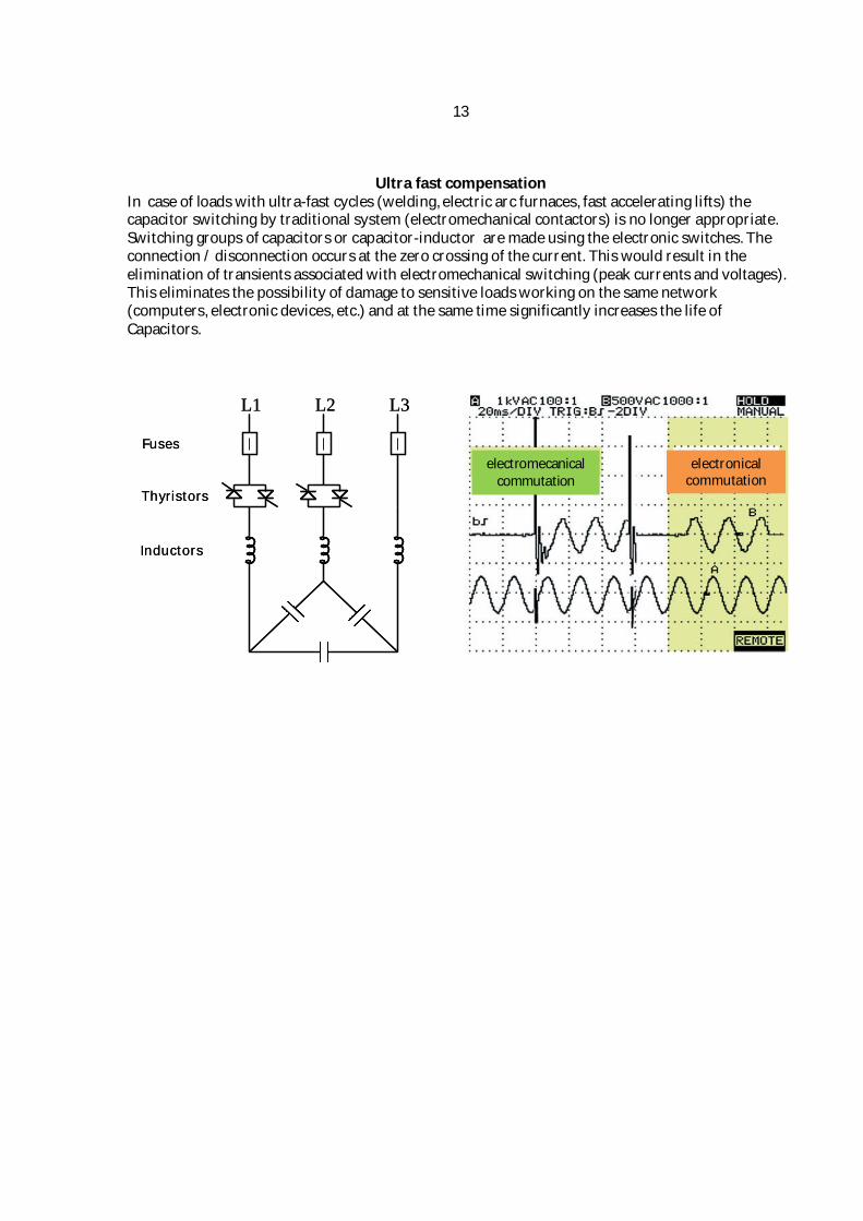
Ultra fast compensation In case of loads with ultra-fast cycles (welding, electric arc furnaces, fast accelerating lifts) the capacitor switching by traditional system (electromechanical contactors) is no longer appropriate. Switching groups of capacitors or capacitor-inductor are made using the electronic switches. The connection / disconnection occurs at the zero crossing of the current. This would result in the elimination of transients associated with electromechanical switching (peak currents and voltages). This eliminates the possibility of damage to sensitive loads working on the same network (computers, electronic devices, etc.) and at the same time significantly increases the life of Capacitors.
Fuses
Thyristors
Inductors
L1 L2 L3
Fuses
Thyristors
Inductors
L1 L2 L3
electromecanical commutation
electronical commutation
14
Individual reactive compensation for modern transformers with reduced no-load losses
Electric motors compensation The table below gives an indication of the maximum power capacitor that can be connected directly to the terminals of an asynchronous motor. But in all cases should be checked if the maximum intensity of the capacitor current [A] does not exceed 90% of the magnetizing current (no load) of the electric motor!
100 200/200 70 95 125 250/250 70 95 150 400/300 95 120 175 400/350 120 185 200 400/400 150 240 225 630/450 150 240 250 630/500 185 2 x 120 275 630/550 185 2 x 120 300 630/600 2 x 95 2 x 150 325 630/630 2 x 95 2 x 150 350 800/700 2 x 120 2 x 185 375 800/750 2 x 120 2 x 185 400 800/800 2 x 150 2 x 240 450 1000/900 2 x 150 2 x 240 500 1000/1000 2 x 185 4 x 150 550 1250/1100 2 x 185 4 x 150 600 1250/1200 4 x 120 4 x 185 650 1250/1250 4 x 120 4 x 185 700 1600/1400 4 x 150 4 x 240 750 1600/1500 4 x 150 4 x 240 800 1600/1600 4 x 150 4 x 240 850 2000/1700 4 x 150 4 x 240 900 2000/1800 4 x 150 4 x 240 950 2000/1900 4 x 185 4 x 300
1000 2000/2000 4 x 185 4 x 300 Recommended section it is the minimum necessary, for single phase cables, in air, at ambient temperature of 30°C.
16
ELNESS srl Drumul Ungurenilor 6 200777 Craiova, Romania