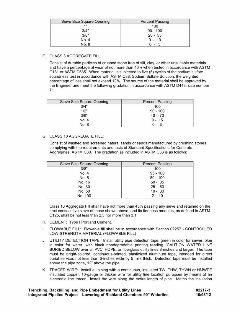
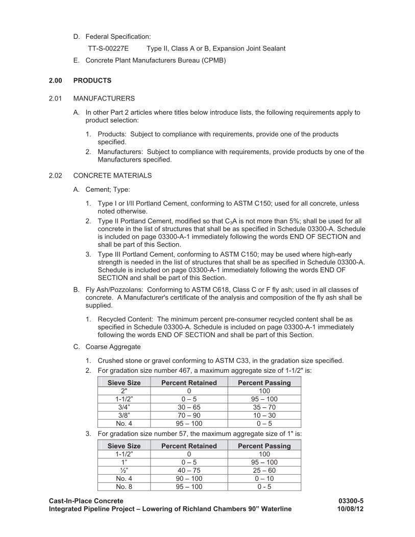
TARRANT REGIONAL WATER DISTRICT AND CITY OF DALLAS TEXAS CITY OF DALLAS, TEXAS SPECIFICATIONS SPECIFICATIONS FOR LOWERING OF RICHLAND CHAMBERS 90” WATERLINE 90 WATERLINE October 2012 DALLAS CITY COUNCIL TARRANT REGIONAL WATER DISTRICT BOARD OF DIRECTORS VICTOR W. HENDERSON, PRESIDENT HAL S. SPARKS III, VICE PRESIDENT JACK STEVENS, SECRETARY MARTY LEONARD, SECRETARY PRO-TEM JIM LANE JAMES M. OLIVER, GENERAL MANAGER DISTRICT 1 - DELIA JASSO DISTRICT 2 - MAYOR PRO-TEM PAULINE MEDRANO DISTRICT 3 - SCOTT GRIGGS DISTRICT 4 - DWAINE R. CARAWAY DISTRICT 5 - VONCIEL JONES HILL DISTRICT 6 - MONICA R. ALONZO DISTRICT 7 CAROLYN R DAVIS DALLAS CITY COUNCIL MAYOR MIKE RAWLINGS DISTRICT 8 - DEPUTY MAYOR PRO-TEM TENNELL ATKINS DISTRICT 9 - SHEFFIE KADANE DISTRICT 10 - JERRY R. ALLEN DISTRICT 11 - LINDA KOOP DISTRICT 12 - SANDY GREYSON DISTRICT 13 - ANN MARGOLIN DISTRICT 14 ANGELA HUNT DISTRICT 7 - CAROLYN R. DAVIS JODY PUCKETT P.E. WATER UTILITIES DIRECTOR DISTRICT 14 - ANGELA HUNT Texas Registered Engineering Firm No. F-2614 IN ASSOCIATION WITH Alan Plummer Associates, Inc. Texas Registered Engineering Firm No. F-13 CP&Y, Inc. Texas Registered Engineering Firm No. F-1741
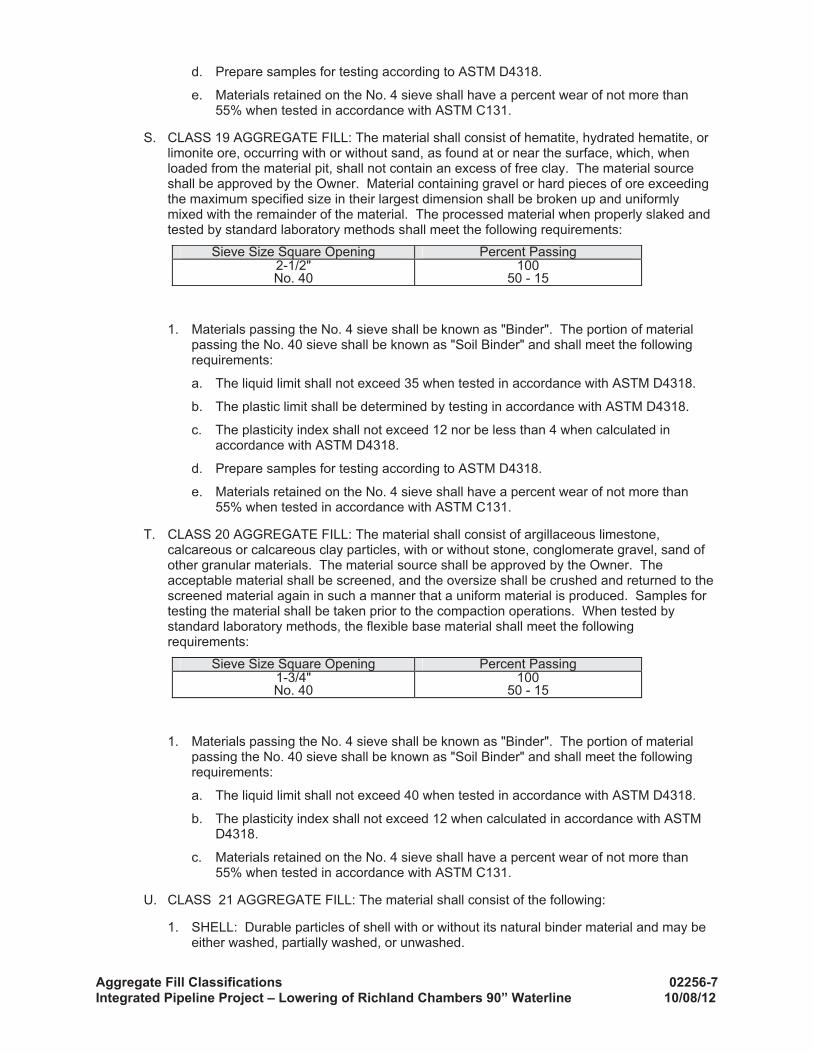
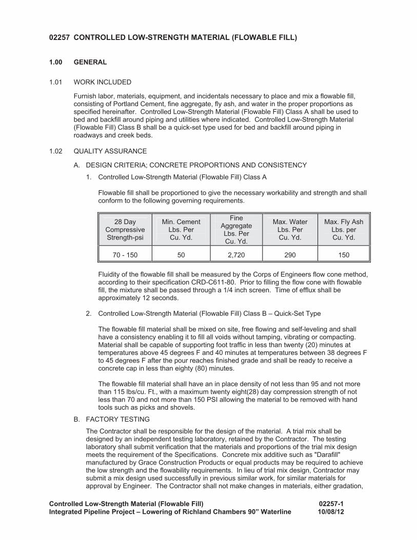
Transcript
TARRANT REGIONAL WATER DISTRICTAND
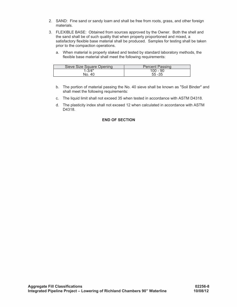
CITY OF DALLAS TEXASCITY OF DALLAS, TEXAS
SPECIFICATIONSSPECIFICATIONS FOR
LOWERING OF RICHLAND CHAMBERS 90” WATERLINE90 WATERLINE
October 2012
DALLAS CITY COUNCILTARRANT REGIONAL WATER DISTRICT
BOARD OF DIRECTORS
VICTOR W. HENDERSON, PRESIDENTHAL S. SPARKS III, VICE PRESIDENT
JACK STEVENS, SECRETARYMARTY LEONARD, SECRETARY PRO-TEM
JIM LANEJAMES M. OLIVER, GENERAL MANAGER
DISTRICT 1 - DELIA JASSODISTRICT 2 - MAYOR PRO-TEM
PAULINE MEDRANO DISTRICT 3 - SCOTT GRIGGSDISTRICT 4 - DWAINE R. CARAWAYDISTRICT 5 - VONCIEL JONES HILLDISTRICT 6 - MONICA R. ALONZODISTRICT 7 CAROLYN R DAVIS
DALLAS CITY COUNCIL
MAYOR MIKE RAWLINGS
DISTRICT 8 - DEPUTY MAYOR PRO-TEMTENNELL ATKINS
DISTRICT 9 - SHEFFIE KADANEDISTRICT 10 - JERRY R. ALLENDISTRICT 11 - LINDA KOOPDISTRICT 12 - SANDY GREYSONDISTRICT 13 - ANN MARGOLINDISTRICT 14 ANGELA HUNTDISTRICT 7 - CAROLYN R. DAVIS
JODY PUCKETT P.E. WATER UTILITIES DIRECTOR
DISTRICT 14 - ANGELA HUNT
Texas Registered Engineering Firm No. F-2614
IN ASSOCIATION WITH
Alan Plummer Associates, Inc.Texas Registered Engineering Firm No. F-13
Table of Contents TOC-1 Integrated Pipeline Project - Lowering of the Richland Chambers 90” Water Line
Tarrant Regional Water District / City Of Dallas Integrated Pipeline Project
Lowering of the Richland Chambers 90” Water Line Standard Specifications
October 2012
TABLE OF CONTENTS DIVISION 0 REQUEST FOR PROPOSALS AND CONTRACTS Section 00301 Basis of GMP for Lowering of Richland Chambers 90” Water Line DIVISION 1 GENERAL REQUIREMENTS Section 01010 Summary of Work 01270 Measurement and Payment 01568 Storm Water Pollution Prevention During Construction DIVISION 2 SITEWORK Section 02111 Clearing and Grubbing 02202 Pipeline Excavation and Backfill 02217 Trenching, Backfilling, and Pipe Embedment for Utility Lines 02220 Trench Safety 02256 Aggregate Fill Classifications 02257 Controlled Low-Strength Material (Flowable Fill) 02262 Geotextile - Subsurface Drainage 02263 Geotextile - Erosion Control 02270 Seeding For Erosion Control 02402 Care of Water During Construction 02504 Flexible Base 02626 Steel Pipe 02630 In-Situ Cement Mortar Lining 02640 Gate Valves 02644 Miscellaneous Pipeline Valves and Pipeline Appurtenances DIVISION 3 CONCRETE Section 03100 Concrete Formwork 03200 Concrete Reinforcement 03300 Cast-in-Place Concrete DIVISION 13 SPECIAL CONSTRUCTION Section 13115 Galvanic Anode Cathodic Protection
October 2012
TARRANT REGIONAL WATER DISTRICT / CITY OF DALLAS
INTEGRATED PIPELINE PROJECT
LOWERING OF RICHLAND CHAMBERS 90” WATERLINE
10/8/12
Lockwood Andrews and Newnam, Inc. TBPE REGISTRATION F-2614
Basis of GMP 00300-1 Integrated Pipeline Project – Lowering of the Richland Chambers 90” 10/08/12
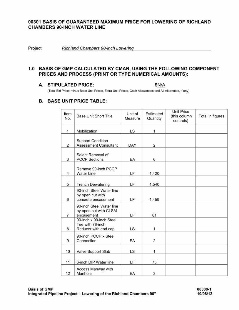
00301 BASIS OF GUARANTEED MAXIMUM PRICE FOR LOWERING OF RICHLAND CHAMBERS 90-INCH WATER LINE
Project: Richland Chambers 90-inch Lowering
1.0 BASIS OF GMP CALCULATED BY CMAR, USING THE FOLLOWING COMPONENT PRICES AND PROCESS (PRINT OR TYPE NUMERICAL AMOUNTS):
A. STIPULATED PRICE: $N/A
(Total Bid Price; minus Base Unit Prices, Extra Unit Prices, Cash Allowances and All Alternates, if any)
B. BASE UNIT PRICE TABLE:
Item No. Base Unit Short Title Unit of
Measure Estimated Quantity
Unit Price (this column
controls) Total in figures
1 Mobilization LS 1
2 Support Condition Assessment Consultant DAY 2
3 Select Removal of PCCP Sections EA 6
4 Remove 90-inch PCCP Water Line LF 1,420
5 Trench Dewatering LF 1,540
6
90-inch Steel Water line by open cut with concrete encasement LF 1,459
7
90-inch Steel Water line by open cut with CLSM encasement LF 81
8
90-inch x 90-inch Steel Tee with 78-inch Reducer with end cap LS 1
9 90-inch PCCP x Steel Connection EA 2
10 Valve Support Slab LS 1
11 6-inch DIP Water line LF 75
12 Access Manway with Manhole EA 3
Basis of GMP 00300-2 Integrated Pipeline Project – Lowering of the Richland Chambers 90” 10/08/12
Item No.
Base Unit Short Title Unit of Measure
Estimated Quantity
Unit Price (this column
controls) Total in figures
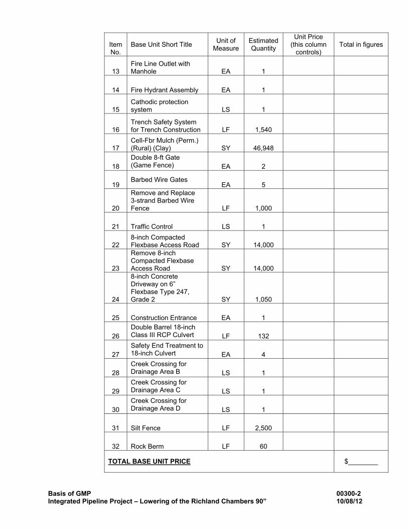
13 Fire Line Outlet with Manhole EA 1
14 Fire Hydrant Assembly EA 1
15 Cathodic protection system LS 1
16 Trench Safety System for Trench Construction LF 1,540
17 Cell-Fbr Mulch (Perm.) (Rural) (Clay) SY 46,948
18 Double 8-ft Gate (Game Fence) EA 2
19 Barbed Wire Gates
EA 5
20
Remove and Replace 3-strand Barbed Wire Fence LF 1,000
21 Traffic Control LS 1
22 8-inch Compacted Flexbase Access Road SY 14,000
23
Remove 8-inch Compacted Flexbase Access Road SY 14,000
24
8-inch Concrete Driveway on 6” Flexbase Type 247, Grade 2 SY 1,050
25 Construction Entrance EA 1
26 Double Barrel 18-inch Class III RCP Culvert LF 132
27 Safety End Treatment to 18-inch Culvert EA 4
28 Creek Crossing for Drainage Area B LS 1
29 Creek Crossing for Drainage Area C LS 1
30 Creek Crossing for Drainage Area D LS 1
31 Silt Fence LF 2,500
32 Rock Berm LF 60
TOTAL BASE UNIT PRICE $________
Basis of GMP 00300-3 Integrated Pipeline Project – Lowering of the Richland Chambers 90” 10/08/12
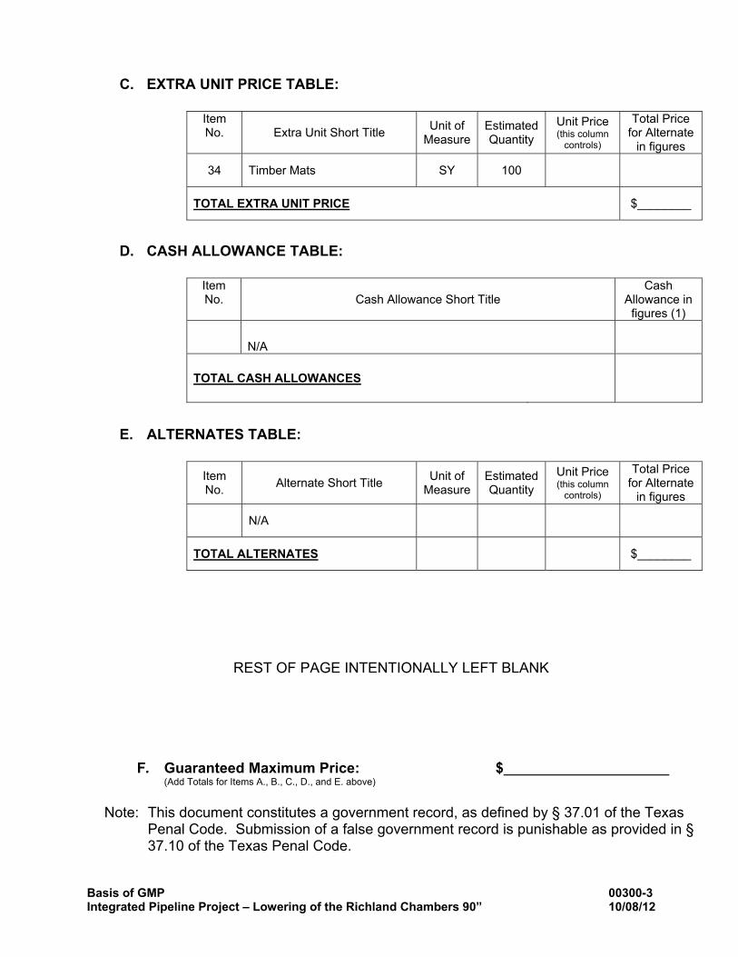
C. EXTRA UNIT PRICE TABLE:
D. CASH ALLOWANCE TABLE:
E. ALTERNATES TABLE:
REST OF PAGE INTENTIONALLY LEFT BLANK
F. Guaranteed Maximum Price: $ (Add Totals for Items A., B., C., D., and E. above)
Note: This document constitutes a government record, as defined by § 37.01 of the Texas
Penal Code. Submission of a false government record is punishable as provided in § 37.10 of the Texas Penal Code.
Item No.
Extra Unit Short Title Unit of
Measure Estimated Quantity
Unit Price (this column
controls)
Total Price for Alternate
in figures
34 Timber Mats SY 100
TOTAL EXTRA UNIT PRICE $________
Item No.
Cash Allowance Short Title
Cash Allowance in
figures (1)
N/A
TOTAL CASH ALLOWANCES
Item No. Alternate Short Title Unit of
Measure Estimated Quantity
Unit Price (this column
controls)
Total Price for Alternate
in figures
N/A
TOTAL ALTERNATES $________
Basis of GMP 00300-4 Integrated Pipeline Project – Lowering of the Richland Chambers 90” 10/08/12
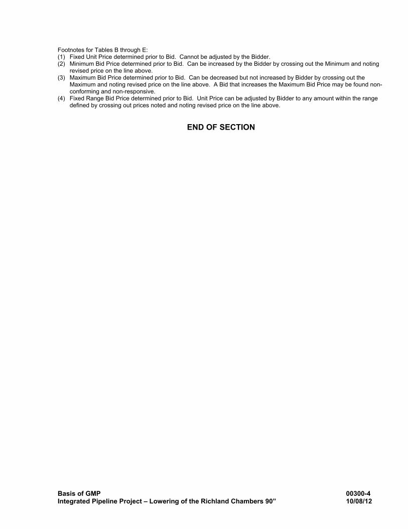
Footnotes for Tables B through E: (1) Fixed Unit Price determined prior to Bid. Cannot be adjusted by the Bidder. (2) Minimum Bid Price determined prior to Bid. Can be increased by the Bidder by crossing out the Minimum and noting
revised price on the line above. (3) Maximum Bid Price determined prior to Bid. Can be decreased but not increased by Bidder by crossing out the
Maximum and noting revised price on the line above. A Bid that increases the Maximum Bid Price may be found non-conforming and non-responsive.
(4) Fixed Range Bid Price determined prior to Bid. Unit Price can be adjusted by Bidder to any amount within the range defined by crossing out prices noted and noting revised price on the line above.
END OF SECTION
01010 Summary of Work
Summary of Work 01010-1 Integrated Pipeline Project - Lowering of the Richland Chambers 90” Water Line 10/08/12
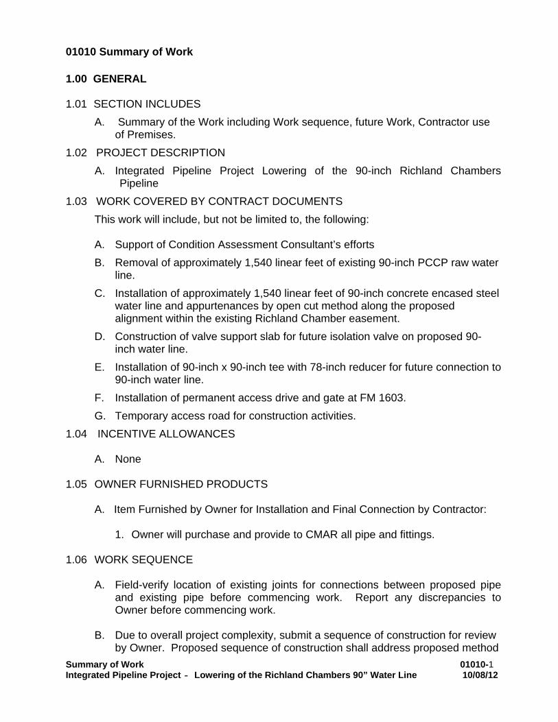
1.00 GENERAL
1.01 SECTION INCLUDES
A. Summary of the Work including Work sequence, future Work, Contractor use of Premises.
1.02 PROJECT DESCRIPTION A. Integrated Pipeline Project Lowering of the 90-inch Richland Chambers
Pipeline 1.03 WORK COVERED BY CONTRACT DOCUMENTS
This work will include, but not be limited to, the following:
A. Support of Condition Assessment Consultant’s efforts B. Removal of approximately 1,540 linear feet of existing 90-inch PCCP raw water
line. C. Installation of approximately 1,540 linear feet of 90-inch concrete encased steel
water line and appurtenances by open cut method along the proposed alignment within the existing Richland Chamber easement.
D. Construction of valve support slab for future isolation valve on proposed 90-inch water line.
E. Installation of 90-inch x 90-inch tee with 78-inch reducer for future connection to 90-inch water line.
F. Installation of permanent access drive and gate at FM 1603. G. Temporary access road for construction activities.
1.04 INCENTIVE ALLOWANCES
A. None 1.05 OWNER FURNISHED PRODUCTS
A. Item Furnished by Owner for Installation and Final Connection by Contractor:
1. Owner will purchase and provide to CMAR all pipe and fittings. 1.06 WORK SEQUENCE
A. Field-verify location of existing joints for connections between proposed pipe
and existing pipe before commencing work. Report any discrepancies to Owner before commencing work.
B. Due to overall project complexity, submit a sequence of construction for review
by Owner. Proposed sequence of construction shall address proposed method
01010 Summary of Work
Summary of Work 01010-2 Integrated Pipeline Project - Lowering of the Richland Chambers 90” Water Line 10/08/12
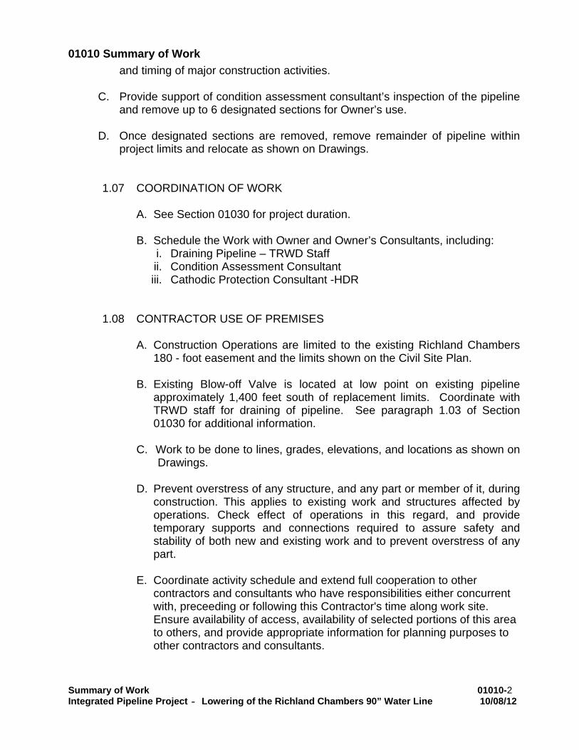
and timing of major construction activities.
C. Provide support of condition assessment consultant’s inspection of the pipeline and remove up to 6 designated sections for Owner’s use.
D. Once designated sections are removed, remove remainder of pipeline within
project limits and relocate as shown on Drawings.
1.07 COORDINATION OF WORK
A. See Section 01030 for project duration.
B. Schedule the Work with Owner and Owner’s Consultants, including: i. Draining Pipeline – TRWD Staff ii. Condition Assessment Consultant iii. Cathodic Protection Consultant -HDR
1.08 CONTRACTOR USE OF PREMISES A. Construction Operations are limited to the existing Richland Chambers
180 - foot easement and the limits shown on the Civil Site Plan.
B. Existing Blow-off Valve is located at low point on existing pipeline approximately 1,400 feet south of replacement limits. Coordinate with TRWD staff for draining of pipeline. See paragraph 1.03 of Section 01030 for additional information.
C. Work to be done to lines, grades, elevations, and locations as shown on
Drawings.
D. Prevent overstress of any structure, and any part or member of it, during construction. This applies to existing work and structures affected by operations. Check effect of operations in this regard, and provide temporary supports and connections required to assure safety and stability of both new and existing work and to prevent overstress of any part.
E. Coordinate activity schedule and extend full cooperation to other
contractors and consultants who have responsibilities either concurrent with, preceeding or following this Contractor's time along work site. Ensure availability of access, availability of selected portions of this area to others, and provide appropriate information for planning purposes to other contractors and consultants.
01010 Summary of Work
Summary of Work 01010-3 Integrated Pipeline Project - Lowering of the Richland Chambers 90” Water Line 10/08/12
F. Construction Access 1. Unless otherwise approved by the Owner, construction access is to
be in accordance with Drawings.
2. Utilize timber mats or other means to maintain construction access during wet condition. Extension of Contract Time due to construction access will not be allowed.
G. Work will be allowed 24 hours per day. Coordinate with Owner a
minimum of two days in advance of work outside regular work hours to verify presence of inspector.
H. Maintain local driveway access to local property owners.
I. Working multiple and separate crews during construction is allowed. J. Field Office:
1. See Section 01500 for requirements.
1.09 INTERPRETATION OF CONFLICTS
A. Should conflicts occur in Contract Documents, request interpretation before proceeding with Work. Such requests shall be preceded by a diligent investigation into Contract Documents. Contain evidence of such investigation in requests for interpretation.
1.10 GENERAL CONSTRUCTION NOTES
A. Field verify existing facilities shown on the drawings by whatever means
necessary (metal detection, probes, excavation, survey, others) prior to excavation for proposed utilities. Field verification work shall be completed prior to excavation for proposed water line. No separate pay.
B. Comply with OSHA Regulations and State of Texas laws concerning
excavation, trenching and shoring as specified in Contract Documents. C. Conduct construction operation under this contract in conformance with
the erosion control practices described in the TPDES program requirements and Document 01568 “Storm Water Pollution Prevention During Construction” and the Storm Water Pollution Prevention Plans included in the construction drawings.
01010 Summary of Work
Summary of Work 01010-4 Integrated Pipeline Project - Lowering of the Richland Chambers 90” Water Line 10/08/12
D. Any pavement, fences, gates, lawns, landscape features, irrigation utilities, landscapes, culverts, inlets, manholes, signs or mail boxes and other improvements not identified for removal and replacement that have been disturbed due to utility construction shall be replaced with same quality material or better at no cost to the Owner.
E. Limits of Clearing and Grubbing include 180 foot easement width from
Sta. 3247+75 to 3263+15, and the width of the access road. Clearing and Grubbing is considered incidental to the water line installation.
1.11 EXISTING UTILITIES
A. Underground utilities exist in the vicinity of this project. While every effort
has been made to show locations for existing utilities, they are approximate and other utilities may exist in the vicinity of this project, which are not shown on these plans. The location and grades of existing utilities are based on as-built information.
B. Public and private utility lines and customer service lines may exist that
are not shown on the construction drawings. Locate, maintain and protect the integrity of these lines. Hand excavation may be required.
1.12 WATER LINES
A. This project shall be built by means of open-cut as noted on the drawings.
B. Water lines shall be constructed in accordance with Integrated Pipeline
Program specifications.
C. All utilities present on these drawings are shown at approximate locations based on the best available information. The contractor shall field determine the exact locations prior to commencing construction. Protect and support existing utilities and structures along the alignment as necessary for construction. He or she shall be fully responsible for any and all damages caused by his or her failure to exactly locate and maintain these underground utilities, at no additional cost to the Owner.
1.13 STORM DRAINAGE
A. Adequate drainage shall be maintained at all times during construction
and any drainage ditch or structure disturbed during construction shall be restored to the satisfaction of the owning authority. All construction storm runoff shall comply with TPDES requirements.
01010 Summary of Work
Summary of Work 01010-5 Integrated Pipeline Project - Lowering of the Richland Chambers 90” Water Line 10/08/12
C. Contractor shall be responsible for removal of siltation in existing storm culverts or channels that result from construction activities associated with this project.
1.14 SAFETY SYSTEMS
A. The plans and any attendant drawings (including shop drawings, as built drawings or record drawings), addenda, change orders and specifications, prepared by Design Consultant., do not extend to or include designs or systems pertaining to the safety of the construction contractor or its employees, agents, or representatives in their performance of the work. The seal of Design Consultant’s registered/licensed professional engineers hereon does not extend to any such safety systems that may now or hereafter be incorporated in these plans. The construction contractor shall prepare or obtain the appropriate safety systems, including the plans and specifications required by House Bill 662 and 665 enacted by the Texas Legislature.
1.15 CONDITION ASSESSMENT
A. After Owner has drained the pipeline, but prior to breaching the pipe, Owner’s Conditional Assessment Consultant may perform in place condition assessment of the existing 90” PCCP pipeline. Support Condition Assessment Consultant’s activities including but not limited to:
1. Dewatering 2. Trench safety 3. Entry to existing 90” pipeline and topside support at existing access
points and support of for confined space entry 4. Temporary lighting 5. Ventilation and air monitoring 6. Replacement of gaskets at access points
B. Owner will designate up to 6 sections of existing PCCP for select
removal. Carefully uncover and remove designated sections in a manner that keeps section intact. Transport, and unload selected sections to a location up to 100 miles from project site to be determined by Owner. Use care when transporting and handling sections to prevent damage.
1.16 CREEK CROSSINGS
A. Prepare and install creek crossings for drainage areas identified and flow conditions provided on Drawings
01010 Summary of Work
Summary of Work 01010-6 Integrated Pipeline Project - Lowering of the Richland Chambers 90” Water Line 10/08/12
B. Upon completion of construction activities, remove creek crossings and restore creek to preconstruction conditions.
1.17 Critical Operations
A. Work impacting critical operation is work occurring after the shutdown of the 90-inch water line and must be completed prior to placing 90-inch water line back in service.
PART 2 PRODUCTS
2.01 TYPE OF PIPE FOR CONSTRUCTION OF WATER LINE
A. Drawings have been prepared on basis of Steel Pipe.
B. Manufacturer and subcontractor selection are within Contractor’s control and will not warrant time extensions due to failure to produce required deliverables within Contract Time. Extension of Contract Time due to non-delivery of Contractor’s choice of pipe manufacturer, which affects Contractor’s schedule, will not be allowed. Contractor to submit pipe material and other critical submittals in a timely manner to allow sufficient review time by Owner and to maintain construction schedule.
C. Provide bends and fittings as required to comply with top of pipe
elevations shown in profile view of Drawings. Call outs for bends and fittings are not identified on Drawings in profile view.
D. No separate payment for restrained or welded joints.
PART 3 E X E C U T I O N (Not Used)
END OF SECTION
Measurement and Payment 01270-1 Integrated Pipeline Project - Lowering of the Richland Chambers 90” Water Line 10/08/12
01270 MEASUREMENT AND PAYMENT
PART 1 GENERAL 1.01 SECTION INCLUDES
A. Procedures for measurement and payment plus conditions for nonconformance assessment and nonpayment for rejected Products.
1.02 MEASUREMENT AND PAYMENT Payment for the following items includes labor, equipment, and materials necessary for completion of the Work in accordance with Drawings and corresponding Specifications. No separate payment will be made for trench excavation, embedment, and backfill. Include cost in unit price for associated bid items included in Document 00301.
A. Mobilization 1. Payment is on a lump sum basis for mobilizing all of the proper and necessary
equipment to the complete the Work and for de-mobilizing all equipment from the work site upon completion.
B. Support Condition Assessment Consultant (Section 01010)
1. Payment is on a unit price basis for each day of condition assessment support. Time for support begins once pipe is drained and condition assessment consultant enters pipeline.
C. Select Removal of PCCP Sections (Section 01010) 1. Payment is on a unit price basis for each existing pipe section identified by Owner,
removed intact, delivered to a site determined by Owner and unloaded.
D. Remove 90-inch PCCP Water Line (Section 01010) 1. Payment is on a unit price basis for each linear foot of 90-inch water removed and
disposed of as shown on Drawings, measured along the center line of the pipe.
E. Trench Dewatering (Section 02217)
1. Payment is on a unit price basis for each linear foot of dewatered trench for 90-inch water line. Dewatering plan must be submitted and approved before payment will be made.
Measurement and Payment 01270-2 Integrated Pipeline Project - Lowering of the Richland Chambers 90” Water Line 10/08/12
2. Dewatering required during course of project to lower water table for other utility installation, construction of structures, removal of standing water, surface drainage seepage, or to protect against rising waters or floods shall be considered incidental to Work, unless otherwise noted.
F. 90-inch Steel Water Line by Open-Cut with Concrete Encasement (Section 02626) 1. Payment is on a unit price basis for each linear foot of 90-inch steel water line
installed, measured along the center line of the pipe. Payment includes concrete encasement.
G. 90-inch Steel Water Line by Open-Cut with CLSM Encasement (Section 02626) 1. Payment is on a unit price basis for each linear foot of 90-inch steel water line
installed, measured along the center line of the pipe. Payment includes CLSM encasement.
H. 90-inch x 90-inch Steel Tee with 78-inch Reducer with End Cap (Detail C-509) 1. Payment is on a lump sum basis for the installation of the tee, reducer and end
cap.
I. 90-inch PCCP x Steel Connection (Section 02626) 1. Payment is on a unit price basis for each 90-inch connection installed.
J. Valve Support Slab (Detail C-507 and C-508)
1. Payment is on a lump sum basis for installation of a valve support on the existing
90-inch water line.
K. 6-inch DIP Water Line (Section 02628) 1. Payment is on a unit price basis for each linear foot of water line installed including
fittings, measured along the center line of the pipe.
L. Access Manway with Manhole (Detail 02626-006) 1. Payment is on a unit price basis for each access manway installed. Payment
includes installation of manhole.
M. Fire Line Outlet with Manhole (Section 01010) 1. Payment is on a unit price basis for each fire line outlet installed. Payment
includes installation of manhole.
Measurement and Payment 01270-3 Integrated Pipeline Project - Lowering of the Richland Chambers 90” Water Line 10/08/12
N. Fire Hydrant Assembly (Section 02643) 1. Payment is on a unit price basis for each fire hydrant assembly installed.
O. Cathodic Protection System (Section 13115)
1. Payment is on a lump sum basis for installation of the cathodic protection system.
P. Trench Safety System for Trench Construction (Section 02220)
1. Payment is on a unit price basis for each linear foot measured along the center line
of the trench, including manholes and other line structures. Trench Safety plan must be submitted and approved before payment will be made.
2. No payment will be made under this section for trench safety systems for structural excavations unless included as a bid item in Document 00300 – Proposal (Bid Form). Include payment for trench safety systems in applicable structural installation sections.
Q. Cell-Fbr Mulch (Perm.) (Rural) (Clay) (Section 02270) 1. Payment is on a unit price basis for each square yard of mulch placed.
2. Limits of Seeding include 180 foot easement width from Sta. 3247+75 to
3263+15, and the width of the 15 –foot temporary access road.
R. Double 8-ft Gate (Game Fence) (Section 02831) 1. Payment is on a unit price basis for each gate installed.
S. Barbed Wire Gates (Section 02831)
1. Payment is on a unit price basis for each gate installed.
T. Remove and replace 3-Strand Barbed Wire Fence (Section 02831)
1. Payment is on a unit price basis for each linear foot of fence removed and
replaced, measured between fence posts.
U. Traffic Control
1. Payment is on a lump sum basis. Include preparation and submittal of traffic control plan if different than shown on Drawings, and provision of traffic control devices, equipment, and personnel necessary to protect the Work and public. Payment will be based on Contractor’s Schedule of Values for traffic control.
V. 8-inch Compacted Flexbase Access Road (Section 02504)
Measurement and Payment 01270-4 Integrated Pipeline Project - Lowering of the Richland Chambers 90” Water Line 10/08/12
1. Payment is on a unit price basis for each square yard of flexible base placed.
W. Remove 8-inch Compacted Flexbase Access Road (Section 02504)
1. Payment is on a unit price basis for each square yard of flexible base removed.
X. 8-inch Concrete Driveway on 6-inch Flexbase Type 247, Grade 2
1. Payment is on a unit price basis for each square yard of driveway placed.
Y. Construction Entrance (Section 01568)
1. Payment is on a unit price basis for each square yard of aggregate placed.
Z. Double Barrel 18-inch Class III RCP Culvert (Section 02435)
1. Payment is on a unit price basis for linear foot of double barrel culvert installed, measured along the center line of double barrel culvert.
AA. Safety End Treatment to 18-inch Culvert
1. Payment is on a unit price basis for each end treatment installed.
BB. Creek Crossing for Drainage Areas (Section 01010)
1. Payment is on a lump sum basis for each drainage area crossed.
CC. Silt Fence (Section 01568)
1. Payment is on a unit price basis for each linear foot measured between limits of beginning and ending stakes.
DD. Rock Berm (Section 01568)
1. Payment is on a unit price basis for each linear foot of berm placed.
EE. Timber Mats (Section 01010)
1. Payment is on a unit price basis for each square yard of timber mats placed.
2. Use of timber mats to be approved by Owner.
END OF SECTION
Storm Water Pollution Prevention During Construction 01568-1Integrated Pipeline Project – Lowering of Richland Chambers 90” Waterline 10/08/12
01568 STORM WATER POLLUTION PREVENTION DURING CONSTRUCTION
1.00 GENERAL
1.01 WORK INCLUDED
A. Furnish labor, materials, equipment, and incidentals necessary to provide storm water pollution prevention for the duration of the construction period including furnishing, installing, and maintaining erosion and sediment control structures and procedures and properly removing the features when no longer required.
B. Develop, implement, and maintain a storm water pollution prevention plan in compliance with Local, State, and Federal requirements. Provide preventive measures to keep sediment and other pollutants from the construction activity from entering any storm water system, including open channels. Comply with the Texas Commission on Environmental Quality General Permit (TXR150000) for storm water discharges from construction activities under the Texas Pollutant Discharge Elimination System (TPDES) program.
C. This specification provides guidelines and Best Management Practices (BMPs) information for the Contractor to use in adhering to all Local, State, and Federal environmental regulations with respect to storm water pollution prevention during construction activity.
1.02 QUALITY ASSURANCE
A. Comply with applicable requirements of all governing authorities having jurisdiction. The Contract Documents are not intended to be prescriptive but rather to convey the intent to provide complete slope protection, erosion control, and storm water pollution prevention for both the Owner's property and adjacent properties.
B. The Contractor shall develop and implement a storm water pollution prevention plan in accordance with TCEQ General Permit TXR150000 prior to the beginning of construction activity.
C. Storm water pollution prevention measures shall be established prior to the beginning of construction and maintained during the entire length of construction until final stabilization has been achieved for the area protected.
D. All land-disturbing activities shall be planned and conducted to minimize the area to be exposed at any one time as well as time of exposure, off-site erosion, sedimentation, and adverse water quality impacts.
E. Surface water runoff originating upgrade of an exposed area shall be managed to minimize erosion and sediment loss during the period of exposure.
F. Install measures to control both the velocity and rate of release so as to minimize erosion and sedimentation of the receiving water body (i.e., ditch, channel, stream) in accordance with regulatory requirements and as directed by the Owner or the Engineer.
G. Periodically clean out and dispose of all sediment and other pollutants as necessary to maintain adequate treatment capacity of each pollution control feature. Clean out and properly dispose of all sediment and other storm water pollutants at the time of completion of the Work.
1.03 SUBMITTALS
A. Submittals shall be in accordance with Section 01300 - SUBMITTALS.
Storm Water Pollution Prevention During Construction 01568-2Integrated Pipeline Project – Lowering of Richland Chambers 90” Waterline 10/08/12
B. Small Construction Activity (>1 Acre but <5 Acres)
1. On small construction projects (disturbed area equal to or greater than one acre and less than five acres) submit a copy of the Construction Site Notice to the Operator of any Municipal Separate Storm Sewer System (MS4) receiving construction site discharge prior to beginning construction activity.
2. Post a copy of the Construction Site Notice at the construction site in a location where it is readily available for viewing by the general public and Local, State, and Federal authorities prior to starting construction activities and maintain the posting until completion of the construction activities.
C. Large Construction Activity (>5 Acres)
1. On large construction projects (more than five acres of disturbed area) submit the following to the TCEQ and the Operator of any Municipal Separate Storm Sewer System (MS4) receiving construction site discharge:
a. Notice of Intent (NOI) at least 48 hours prior to beginning construction activity.Construction activity may commence 24 hours after the submittal of an electronic NOI.
b. Notice of Change (NOC) letter when relevant facts or incorrect information was submitted in the NOI, or if relevant information in the NOI changes during the course of construction activity.
c. Notice of Termination (NOT) when the construction project has been completed and stabilized.
2. Post a copy of the NOI at the construction site in a location where it is readily available for viewing by the general public and Local, State, and Federal authorities prior to starting construction activities and maintain the posting until completion of the construction activities.
D. For small and large projects, maintain copies of a schedule of major construction activities, inspection reports, and revision documentation with the storm water pollution prevention plan (SWPPP) required under the TPDES General Permit (TXR150000) for Storm Water Discharges from Construction Activities.
1.04 JOB CONDITIONS; CODES AND ORDINANCES
Comply with the local codes and ordinances. If local codes and ordinances require more stringent or additional storm water pollution prevention measures during construction beyond those required by State and Federal regulations, the Contractor shall provide such measures at no additional cost.
2.00 PRODUCTS
2.01 MATERIALS
A. All materials used for storm water pollution prevention shall meet the minimum design and specification requirements identified below for commonly used sediment loss prevention practices referenced from the North Central Texas Council Of Governments (NCTCOG) integrated Storm Water Management (iSWM) Design Manual for Construction. The Contractor shall use appropriate control devices to protect against storm water pollution from construction site activity.
B. Erosion Control Blankets to hold seed and soil in place until vegetation is established on disturbed areas are subject to the following design criteria:
1. The type and class of erosion control mat must be specified as appropriate for the slope of the area to be protected and the anticipated length of service.
Storm Water Pollution Prevention During Construction 01568-3Integrated Pipeline Project – Lowering of Richland Chambers 90” Waterline 10/08/12
2. Erosion control blankets must meet the applicable Texas Department of Transportation (TxDOT) Minimum Performance Standards for TxDOT as provided in its Erosion Control Report and/or be listed on the most current annual Approved Products List for TxDOTapplicable to TxDOT Item 169 Soil Retention Blanket and its Special Provisions.
C. Silt Fences for perimeter controls located downstream of disturbed areas are subject to the following design criteria:
1. If 50% or less soil by weight passes the U.S. Standard sieve No. 200, select the apparent opening size (A.O.S.) to retain 85% of the soil.
2. If 85% or more of soil by weight passes the U.S. Standard sieve No. 200, silt fences shall not be used unless the soil mass is evaluated and deemed suitable by a soil scientist or geotechnical engineer concerning the erodibility of the soil mass, dispersive characteristics, and the potential grain-size characteristics of the material that is likely to be eroded.
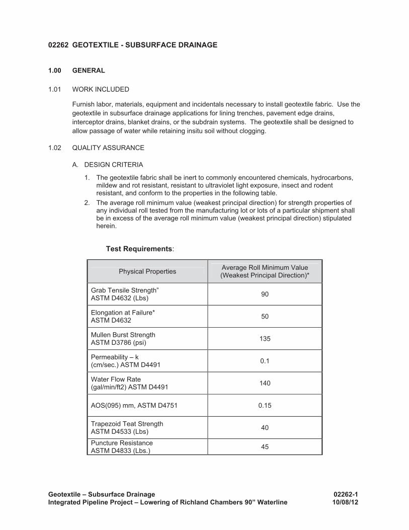
3. Silt fence fabric must meet the following minimum criteria:
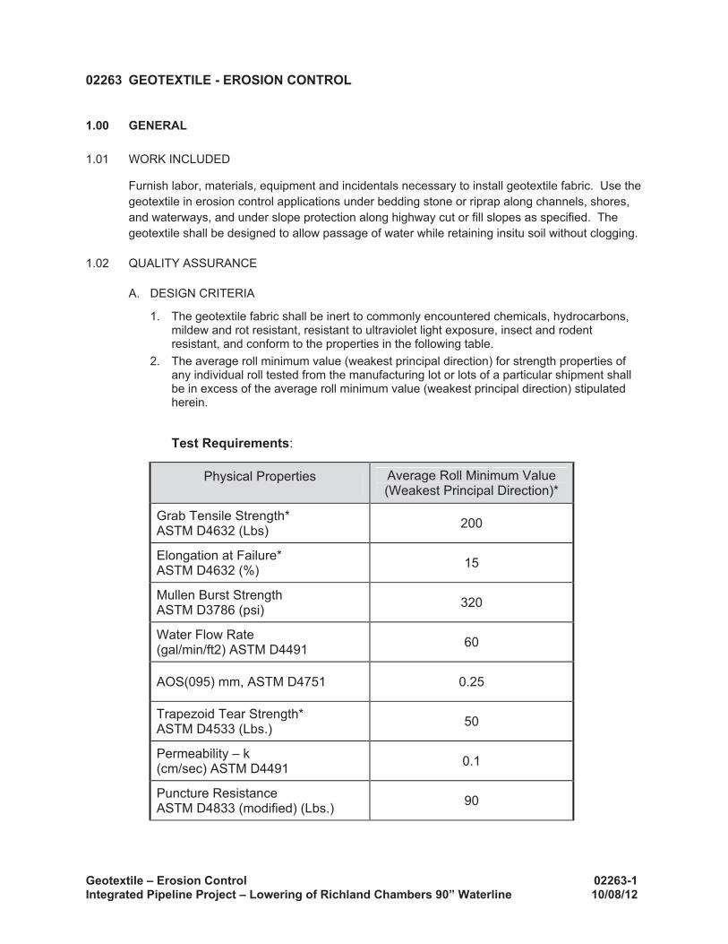
a. Tensile Strength, ASTM D4632 Test Method for Grab Breaking Load and Elongation of Geotextiles, 90-lbs.
b. Puncture Rating, ASTM D4833 Test Method for Index Puncture Resistance of Geotextiles, Geomembranes, and Related Products, 60-lbs.
c. Mullen Burst Rating, ASTM D3786 Standard Test Method for Hydraulic Bursting Strength of Textile Fabrics-Diaphragm Bursting Strength Tester Method, 280-psi.
d. Apparent Opening Size, ASTM D4751 Test Method for Determining Apparent Opening Size of a Geotextile, U.S. Sieve No. 70 (max) to No. 100 (min).
e. Ultraviolet Resistance, ASTM D4355. Minimum 70 percent.
4. Filter stone for an overflow structure shall be 1-1/2” washed stone containing no fine material. Angular shaped stone is preferable to rounded shaped stone.
5. Fence posts shall be galvanized steel or equivalent and may be T-section or L-section, 1.3 pounds per linear foot minimum, and 4 feet in length minimum. Wood Posts may be used depending on anticipated length of service and provided they are 4 feet in length minimum and have a nominal cross section of 2 inches by 4 inches for pine or 2 inches by 2 inches for hardwoods.
6. Silt fence shall be supported by galvanized steel wire fence fabric as follows:
a. 4” x 4” mesh size, W1.4/1.4, minimum 14-gauge wire fence fabric;
b. Hog wire, 12-gauge wire, small openings installed at bottom of silt fence;
c. Standard 2” x 2” chain link fence fabric; or
d. Other welded or woven steel fabrics consisting of equal or smaller spacing as that listed herein and appropriate gauge wire to provide support.
D. Inlet protection used in new developments that include new inlets or roads with new curb inlets or during repairs to existing roadways are subject to the following design criteria:
1. Filter fabric protection shall be designed and maintained in a manner similar to a silt fence.
2. Where applicable, filter fabric, posts, and wire backing shall meet the material requirements specified in the silt fence design requirements.
3. Filter gravel shall be ¾ inch (Block and Gravel Protection) or 1-1/2 to 2 inch (Excavated Impoundment Protection) washed stone containing no fines. Angular shaped stone is preferable to rounded shapes.
4. Concrete blocks shall be standard 8” x 8” x 16” concrete masonry units.
Storm Water Pollution Prevention During Construction 01568-4Integrated Pipeline Project – Lowering of Richland Chambers 90” Waterline 10/08/12
E. Stone Outlet Sediment Traps used in situations where flows are concentrated in a drainage swale or channel are subject to the following design criteria:
1. The embankment shall be placed on geotextile fabric meeting the following minimum criteria:
a. Tensile Strength, ASTM D4632 Text Method for Grab Breaking Load and Elongation of Geotextiles, 250-lbs.
b. Puncture Rating, ASTM D4833 Test Method for Index Puncture Resistance of Geotextiles, Geomembranes, and Related Products, 135-lbs.
c. Mullen Burst Rating, ASTM D3786 Standard Test Method for Hydraulic Bursting Strength of Textile Fabrics-Diaphragm Bursting Strength Tester Method, 420-psi.
d. Apparent Opening Size, ASTM D4751 Test Method for Determining Apparent Opening Size of a Geotextile, U.S. Sieve No. 20 (max).
F. Sediment Basins used as treatment devices for sites with disturbed areas of 10 acres and larger that are part of a common drainage area are subject to the following design criteria:
1. The sediment basin shall have minimum design dewatering time of 36 hours.
G. Check Dams used for long drainage swales or ditches to reduce erosive velocities are subject to the following design criteria:
1. Use geotextile filter fabric under check dams exceeding 18 inches in height. The fabric shall meet the material specified for the Stone Outlet Sediment Trap discussed above.
2. Rock Check Dams
a. Stone shall be well graded with size range from 1-1/2 to 3-1/2 inches in diameter depending on expected flows.
b. Rock Check Dams should be triangular in cross section with side slopes of 1:1 or flatter on the upstream side and 2:1 or flatter on the downstream side.
3. Sand Bag Check Dams
a. Sand Bag Check Dams should have a maximum flow through rate of 0.1 cfs per square foot of surface with a minimum top width of 16 inches and bottom width of 48 inches. Bags should be filled with coarse sand, pea gravel, or filter stone that is clean and free of deleterious material.
b. Bag length shall be 24-inches to 30-inches, width shall be 16-inches to 18-inches and thickness shall be 6-inches to 8-inches and having an approximate weight of 40-pounds.
c. Bag material shall be polypropylene, polyethylene, polyamide, or cotton burlap woven fabric, minimum unit weight 4-ounces-per-square-yard, Mullen burst strength exceeding 300-psi as determined by ASTM D3786 Standard Test Method for Hydraulic Bursting Strength of Textile Fabrics-Diaphragm Bursting Strength Tester Method, and ultraviolet stability exceeding 70 percent.
d. PVC pipes may be installed through the Sand Bag Dam near the top to allow for controlled flow through the dam. Pipe should be schedule 40 or heavier polyvinyl chloride (PVC) having a nominal internal minimal diameter of 4 inches.
H. Stabilized Construction Entrances used for sites in which significant truck traffic occurs on a daily basis are subject to the following design criteria:
1. The geotextile fabric must meet the following minimum criteria:
a. Tensile Strength, ASTM D4632 Test Method for Grab Breaking Load and Elongation of Geotextiles, 300-lbs.
Storm Water Pollution Prevention During Construction 01568-5Integrated Pipeline Project – Lowering of Richland Chambers 90” Waterline 10/08/12
b. Puncture Strength, ASTM D4833 Test Method for Index Puncture Resistance of Geotextiles, Geomembranes, and Related Products, 120-lbs.
c. Mullen Burst Rating, ASTM D3786 Standard Test Method for Hydraulic Bursting Strength of Textile Fabrics-Diaphragm Bursting Strength Tester Method, 600-psi.
d. Apparent Opening Size, ASTM D4751 Test Method for Determining Apparent Opening Size of a Geotextile, U.S. Sieve No. 40 (max).
I. Stone stabilized entrance pads must meet the more stringent of the requirements listed above or Section 02256 – Aggregate Fill Classification. The stone shall be a minimum of 3 to 5-inch coarse aggregate.
J. Filter aggregate must meet the more stringent of the requirements listed above or Section 02256 – Aggregate Fill Classification.
K. Geotextile materials must meet the more stringent of the requirements listed above or Section 02263 – Geotextile: Erosion Control.
L. Alternative pollution prevention measures selected by the Contractor shall be identified from one or more of the following reference sources, as appropriate for the region of the construction activity:
1. City of Austin Environmental Criteria Manual
2. North Central Texas Council of Governments (NCTCOG) integrated Storm Water Management (iSWM) Design Manual for Construction
3. Harris County/Harris County Flood Control District/City of Houston Storm Water Management Handbook for Construction Activities
3.00 EXECUTION
3.01 PREPARATION
A. Prepare a storm water pollution prevention plan (SWPPP) in accordance with applicable permit requirements for construction activity. Develop the SWPPP in conformance with TPDES General Permit (TXR150000) for Storm Water Discharges from Construction Activities and any applicable Local requirements.
B. Prepare and implement the SWPPP prior to the beginning of construction activity in accordance with Local, State, and Federal requirements.
C. Owner may require Contractor to install storm water pollution prevention devices and/or practices during construction in addition to those required under the approved storm water pollution plan. Contractor shall remain solely responsible for complying with all Local, State, and Federal requirements.
3.02 INSTALLATION
A. Erosion Control Blankets to hold seed and soil in place until vegetation is established on disturbed areas are subject to the following installation criteria:
1. Prior to the installation of any erosion control matting, all rocks, dirt clods, stumps, roots, trash, and any other obstructions that would prevent the mat from lying in direct contact with the soil shall be removed. Anchor trenching shall be located along the entire perimeter of the installation area, except for small areas with less than 2 percent slope.
2. Installation and anchoring shall conform to the recommendations shown within the Supplier’s published literature for the approved erosion control blanket. Joints and overlapping material shall be securely fastened.
Storm Water Pollution Prevention During Construction 01568-6Integrated Pipeline Project – Lowering of Richland Chambers 90” Waterline 10/08/12
3. After installation, check blankets for uniform contact with the soil, security of the lap joints, and flushness of the staples with the ground.
B. Silt Fences for perimeter controls located downstream of disturbed areas are subject to the following installation criteria:
1. Construct fences along a line of constant elevation (along a contour line if possible).
2. Maximum drainage area shall be 0.25 acre per 100 linear feet of silt fence.
3. Maximum flow to any 20 foot section of silt fence shall be 1 CFS.
4. Maximum distance of flow to silt fence shall be 200 feet or less. If the slope exceeds 10 percent, the flow distance shall be less than 50 feet.
5. Maximum slope adjacent to the fence shall be 2:1.
6. Stone overflow structures or other outlet control devices shall be installed at all low points along the fence or spaced at approximately 300 feet if there is no apparent low point.
7. A 6-inch wide trench is to be cut 6 inches deep at the toe of the fence to allow the fabric to be laid below the surface and backfilled with compacted earth or gravel to prevent bypass of runoff under the fence. Fabric shall overlap at abutting ends a minimum of 3 feet and shall be joined such that no leakage or bypass occurs.
8. Sufficient room for the operation of sediment removal equipment shall be provided between the silt fence and other obstructions in order to properly maintain the fence.
9. The ends of the fence shall be turned upstream to prevent bypass of storm water.
C. Inlet protection for new developments that include new inlets or roads with new curb inlets or during repairs to existing roadways are subject to the following installation criteria:
1. Maintain barricades, signs, and safety features around the work in accordance with all provisions of the latest edition of the Manual on Uniform Traffic Control Devices (MUTCD).when installing inlet protection on publicly traveled streets or in developed areas. Ensure that inlet protection is properly designed, installed, and maintained to avoid flooding of the roadway or adjacent properties and structures.
2. Maximum depth of flow shall be 8 inches or less.
3. Positive drainage is critical in the design of inlet protection. If overflow is not provided for at the inlet, excess flows shall be routed through established swales, streets, or other watercourses to minimize damage due to flooding.
4. Filter Barrier Protection – Silt Fence shall consist of nylon geotextile supported by wire mesh, W1.4 X W1.4, and galvanized steel posts set a minimum of 1 foot depth and spaced not more than 6 feet on center. A 6-inch wide trench is to be cut 6 inches deep at the toe of the fence to allow the fabric to be laid below the surface and backfilled with compacted earth or gravel. This entrenchment prevents any bypass of runoff under the fence. If the inlet is installed within a paved area, provide sufficient material overlap at the base to allow for anchorage of the fabric to the concrete inlet slab by sand bags or other means in order to prevent bypass or runoff under the fence.
5. Block and Gravel Protection (Curb and Drop Inlets) – Concrete blocks are to be placed on their sides in a single row around the perimeter of the inlet, with ends abutting.Openings in the blocks should face outward, not upward. ½” x ½” wire mesh shall then be placed over the outside face of the blocks covering the holes. Filter stone shall then be piled against the wire mesh to the top of the blocks with the base of the stone being a minimum of 18 inches from the blocks. Alternatively, where loose stone is a concern (streets, etc.), the filter stone may be placed in appropriately sized geotextile fabric bags.Periodically remove and clean the stone or replace it with new stone when the stone filter becomes clogged.
6. Excavated Impoundment Protection – An excavated impoundment shall be sized to provide a storage volume of between 1800 and 3600 cubic feet per acre of disturbed
Storm Water Pollution Prevention During Construction 01568-7Integrated Pipeline Project – Lowering of Richland Chambers 90” Waterline 10/08/12
area. The trap shall have a minimum depth of one foot and a maximum depth of 2 feet as measured from the top of the inlet and shall have side slopes of 2:1 or flatter. Install weep holes in the inlet walls to allow for the complete dewatering of the trap. When the storage capacity of the impoundment has been reduced by one-half, remove the silt and dispose of it at an approved location.
7. Inlet inserts are commercially available to remove sediment, constituents (pollutants) adsorbed to sediment, and oil and grease. Perform maintenance to remove sediment and debris that could clog the filters. Inlet inserts must have a bypass function to prevent flooding from clogging or high flows.
D. Stone Outlet Sediment Traps for situations where flows are concentrated in a drainage swale or channel are subject to the following installation criteria:
1. The maximum drainage area contributing to the trap shall be 10 acres. For larger drainage areas a sediment basin shall be used.
2. The minimum storage volume shall be 1800 cubic feet per acre of disturbed land draining to the device.
3. The surface area of the design storage shall be 1% of the area draining to the device.
4. The maximum embankment height shall be 6 feet as measured from the toe of the slope on the downstream side.
5. Minimum width of the embankment at the top shall be 2 feet.
6. Embankment slope shall be 1:5:1 or flatter.
7. The embankment shall have a depressed area to serve as the outlet with a minimum width of 4 feet.
8. A six inch minimum thickness layer of ¾ to 2 inch (1-½ inch nominal) well graded filter stone shall be placed on the face of the embankment.
9. The embankment shall be comprised of well graded stone with a size range of 6 to 12 inches in diameter. The stone may be enclosed in wire mesh or a gabion basket and anchored to the channel bottom to prevent washing away.
10. The outlet shall be designed to have a minimum freeboard of 6” at design flow.
11. Geotextile fabric, covered with a layer of stone, shall extend past the base of the embankment on the downstream side a minimum of 2 feet.
E. Sediment Basins for treatment devices for sites with disturbed areas of 10 acres and larger that are part of a common drainage area are subject to the following installation criteria:
1. Minimum capacity of the basin shall be the calculated volume of runoff from a 2-year, 24-hour duration storm event.
2. Deposited sediment shall be removed when the storage capacity of the basin has been reduced by 20%.
3. Minimum width of the embankment at the top shall be 8 feet.
4. Embankment slope shall be 3:1 or flatter.
5. Maximum embankment height shall be 6 feet as measured from the toe of slope on the downstream side. Sediment basins with embankments exceeding 6 feet are regulated by the Texas Commission on Environmental Quality (TCEQ) and must meet specific requirements for dam safety.
6. The basin outlet shall be designed to accommodate a 25-year design storm without causing damage to the containment structure.
7. The basin must be laid out such that the effective flow length of the basin should be at least twice the effective flow width.
Storm Water Pollution Prevention During Construction 01568-8Integrated Pipeline Project – Lowering of Richland Chambers 90” Waterline 10/08/12
8. The outlet of the outfall pipe (barrel) shall be stabilized with riprap or other form of stabilization with design flows and velocities based on 25-year design storm peak flows. For velocities in excess of 5 feet per second, velocity dissipation measures should be used to reduce outfall velocities.
9. The effectiveness of sediment basins may be increased by using baffles to prevent short-circuiting of flow through the basin.
F. Check Dams for long drainage swales or ditches to reduce erosive velocities are subject to the following installation criteria:
1. Check Dams shall be placed at a distance and height to allow small pools to form between each one. Typically, dam height should be between 18” and 36”. Dams shall be spaced such that the top of the downstream dam is at the same elevation as the toe of the upstream dam.
2. Major flows (greater than 2-year design storm) must pass the check dam without causing excessive upstream flooding.
3. Check dams should be used in conjunction with other sediment reduction techniques prior to releasing flow offsite.
G. Stabilized Construction Entrances for sites in which significant truck traffic occurs on a daily basis are subject to the following installation criteria:
1. Stabilized Construction Entrances are to be constructed such that drainage across the entrance is directed to a controlled, stabilized outlet on site with provisions for storage, proper filtration, and removal of wash water.
2. The entrance must be sloped away from the paved surface so that storm water is not allowed to leave the site onto roadways.
3. Minimum width of entrance shall be 15 feet.
4. Stone shall be placed in a layer of at least 12-inch thickness. The stone shall be a minimum of 3 to 5-inch coarse aggregate.
5. Prevent shortcutting of the full length of the construction entrance by installing barriers as necessary.
6. Vehicles shall not be permitted to track or drop sediment onto paved roads, streets, or parking lots. When necessary, vehicles must be cleaned to remove sediment prior to entrance onto paved areas. When washing is required, it shall be done on a constructed wheel wash facility that drains into an approved sediment trap or sediment basin or other sedimentation/filtration device.
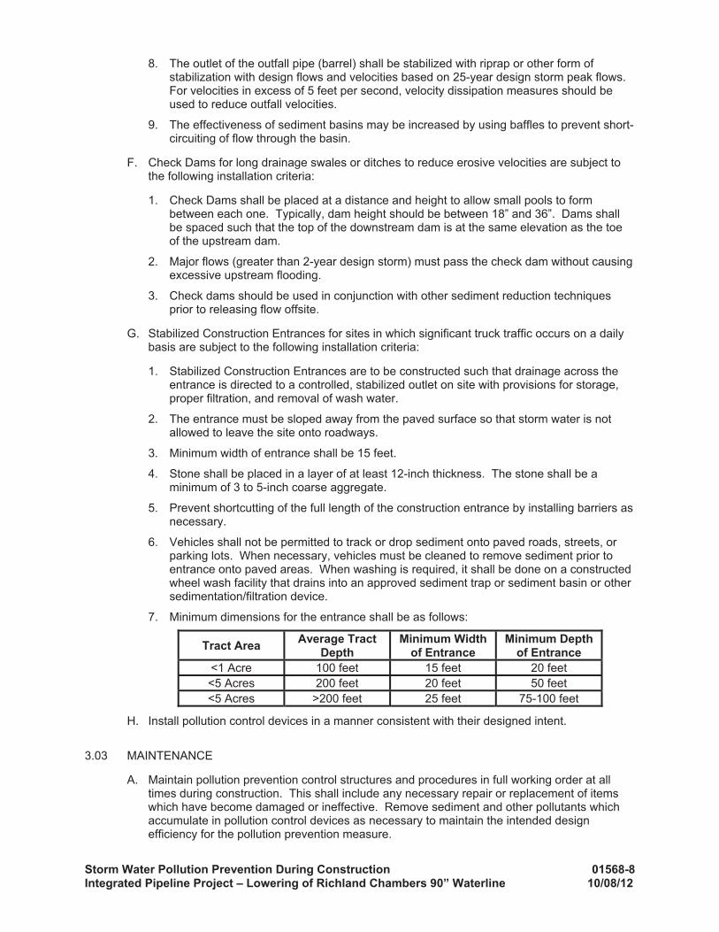
7. Minimum dimensions for the entrance shall be as follows:
H. Install pollution control devices in a manner consistent with their designed intent.
3.03 MAINTENANCE
A. Maintain pollution prevention control structures and procedures in full working order at all times during construction. This shall include any necessary repair or replacement of items which have become damaged or ineffective. Remove sediment and other pollutants which accumulate in pollution control devices as necessary to maintain the intended design efficiency for the pollution prevention measure.
Storm Water Pollution Prevention During Construction 01568-9Integrated Pipeline Project – Lowering of Richland Chambers 90” Waterline 10/08/12
B. Dispose properly of trash, debris, and other pollutants.
C. Place sediment material in approved earth spoil areas or return the sediment material to the area from which it eroded.
D. Maintain pollution prevention structures and procedures until construction is complete for the area protected and until the site achieves final stabilization. Unless more stringently defined by Local, State, or Federal requirements, final stabilization is defined as achieving 70 percent of background vegetative cover or placement of permanent cover, such as concrete or asphalt.
E. Upon completion of construction and achievement of final stabilization, properly remove the temporary pollutant control structures and complete the area as indicated. Pollution control devices made of organic materials designed to degrade naturally in place will not require removal, unless specifically required by the Owner or Engineer.
F. Erosion Control Blankets shall be inspected regularly (at least as often as required by the TPDES Construction General Permit) for bare spots caused by weather related events.Missing or loosened blankets must be replaced or re-anchored. Also check for excess sediment deposited from runoff. Remove sediment and/or replace blanket as necessary. In addition, determine the source of excess sediment and implement appropriate Best Management Practices (BMPs) to control the erosion.
G. Silt Fences shall be inspected regularly (at least as often as required by the TPDES Construction General Permit) for buildup of excess sediment, undercutting, sags, and other failures. Sediment should be removed when it reaches approximately one-half the height of the fence. In addition, determine the source of excess sediment and implement appropriate Best Management Practices (BMPs) to control the erosion. If the fabric becomes damaged or clogged, it shall be repaired or replaced as necessary.
H. Inlet Protection shall be inspected regularly (at least as often as required by the TPDES Construction General Permit). When silt fences are also used and the fabric becomes clogged, it should be cleaned or, if necessary, replaced. Also, sediment should be removed when it reaches approximately one-half the height of the inlet protection device. If a sump is used, sediment should be removed when the volume of the basin is reduced by 50%.
For systems using filter stone, when the filter stone becomes clogged with sediment, the stones must be pulled away from the inlet and cleaned or replaced. Dispose of clogged filter stone in an approved location.
I. Stone Outlet Sediment Traps shall be inspected regularly (at least as often as required by the TPDES Construction General Permit) to check for clogging of the void spaces between stones. If the aggregate appears to be silted in such that efficiency is diminished, the stone shall be replaced.
Deposited sediment shall be removed when the depth of sediment is equal to one-third of the height of the embankment as measured from the original toe of slope to the crest of the outlet, or has reached a depth of one foot, whichever is less. The removed sediment shall be stockpiled or redistributed in areas that are protected from erosion.
J. Sediment Basins shall be inspected regularly (at least as often as required by the TPDES Construction General Permit) to check for damage and to insure that obstructions are not diminishing the effectiveness of the structure. Sediment shall be removed and the basin shall be regraded to its original dimensions when the capacity of the impoundment has been reduced to 20% of its original storage capacity. The removed sediment shall be stockpiled or redistributed in areas that are protected by erosion and sediment controls.
K. Check Dams shall be inspected regularly (at least as often as required by the TPDES Construction General Permit). Remove silt when it reaches approximately 1/3 the height of the dam or 12 inches in height, whichever is less.
Storm Water Pollution Prevention During Construction 01568-10Integrated Pipeline Project– Lowering of Richland Chambers 90” Waterline 10/08/12
L. Stabilized Construction Entrances shall be inspected regularly (at least as often as required by the TPDES Construction General Permit). When sediment has substantially clogged the void area between the rocks, the aggregate mat shall be washed down or replaced. Periodic re-grading and top dressing with additional stone shall be done to keep the efficiency of the entrance from diminishing. If the stabilized construction entrance is not effectively removing sediment from wheels, then a wheel wash shall be implemented.
3.04 FIELD QUALITY CONTROL
In the event of conflict between the specified requirements and storm water pollution control laws, rules, or regulations, or other Local, State, or Federal agencies, the more restrictive laws, rules, or regulations shall apply.
3.05 SCHEDULES
Prior to start of construction, submit schedules to the Owner and Engineer for accomplishment of temporary and permanent erosion control work in connection with required clearing and grubbing, grading, construction, and paving. Include a proposed method of erosion and dust control on haul roads and borrow pits and a plan for disposal of waste materials in the submittal.
END OF SECTION
Clearing and Grubbing 02111-1 Integrated Pipeline Project - Lowering of Richland Chambers 90” Waterline 10/08/12
02111 CLEARING AND GRUBBING
1.00 GENERAL
1.01 WORK INCLUDED
A. This Section sets forth the requirements for clearing and grubbing the reservoir sites and other facilities as indicated in the Drawings.
B. Furnish labor, materials, equipment, and incidentals necessary to clear, grub, and dispose of cleared and grubbed materials. Maintain tools and other equipment necessary to completed specified work.
C. The work does not include clearing and grubbing for large diameter waterlines or utility lines unless otherwise noted on Drawings. Work shall be performed in accordance with Section 02202 - PIPELINE EXCAVATION AND BACKFILL and Section 02217 - TRENCHING, BACKFILLING AND PIPE EMBEDMENT.
1.02 JOB CONDITIONS
A. Debris, trash, or rubbish resulting from clearing and grubbing shall become property of the Contractor. It shall be promptly disposed of in compliance with the applicable ordinances.
2.00 EXECUTION
2.01 CLEARING
A. Thoroughly clear (1) to the limits of 10 feet outside the areas to be occupied by the embankment or structure or access road, (2) areas of required excavation or borrow, and (3) to any additional limits indicated on the plans. Clearing shall consist of the felling, cutting up, and the satisfactory disposal of trees and other vegetation, together with the down timber, snags, brush, rubbish, fences, and debris occurring within the area to be cleared. Cut off trees, other vegetation, stumps, roots, and brush in the area flush with or slightly below the original ground surface. Trees and brush outside the limits of the indicated areas to be cleared, but within the immediate vicinity of the work that interfere with or retard the progress of construction operations, may be removed upon receipt of the approval of the Owner. Clearing consists of removal flush with the ground surface.
2.02 GRUBBING
A. Thoroughly grub (1) the areas to be occupied by the embankment and structures, (2) areas of excavation for which the excavated material is to be used as fill, and (3) to any additional limits indicated. Grubbing shall consist of the removal and disposal of stumps and roots larger than 1" in diameter to the depth indicated, matted roots, abandoned structures, abandoned concrete foundations, and concrete floor slabs.
B. In foundation areas, excavate and remove stumps, roots, logs, or other timber more than 1" in diameter, matted roots, and other vegetative matter, and debris not suitable for foundation purposes to a depth not less than 18" below the final foundation ground elevation. Refill depressions excavated for and by the grubbing operations in the embankment area as specified in Section 02252 - COMPACTED FILL FOR EMBANKMENTS. Grubbing shall be completed at least 200 feet in advance of stripping operations, as indicated in Section 02223 - EXCAVATION.
C. Remove timber, logs, stumps, roots, brush, rotten wood, and other refuse from the clearing and grubbing operations from the Owner's property. No burning shall be allowed.
D. Disposal of materials in streams shall not be permitted and no material shall be piled in stream channels or in areas where it might be washed away by floods. Timber within the areas to be cleared shall become the property of the Contractor, and the Contractor may cut, trim, hew, saw, or otherwise dress felled timber within the limits of the Owner's property, provided timber and waste material is disposed of in a satisfactory manner.
END OF SECTION
Pipeline Excavation and Backfill 02202-1 Integrated Pipeline Project – Lowering of Richland Chambers 90” Waterline 10/08/12
02202 PIPELINE EXCAVATION AND BACKFILL
1.00 GENERAL
1.01 WORK INCLUDED
A. Furnish labor, materials, equipment and incidentals necessary to excavate and backfill as required for the construction of the pipeline facilities shown on the drawings to the line, grade and extent indicated.
B. Any work specifically directed by the Contract Documents to be performed in accordance with Section 02202.
C. This Section does not include backfill and embedment of storm drains, drain lines, waterlines 24-inch or smaller in diameter, sewer lines, and miscellaneous utility relocations.
1.02 SUBMITTALS
A. Submittals shall be in accordance with Section 01300 - SUBMITTALS and shall include:
1. Certified test reports for embedment material, coarse gravel, and flexbase. Certified Test Reports shall be from an independent laboratory paid for by the Contractor. Test reports shall include sieve analysis, soil classification, percentage of wear, Atterburg limits, and soil resistivity tests for embedment material.
2. Submit five gallon samples of proposed embedment material at least two weeks prior to initial pipe laying to allow the Owner’s laboratory to perform density test standards. Coordinate with the Engineer or Owner’s Independent Laboratory on site collection of sample as directed by the Owner.
3. Submit Record Data showing station and elevation of existing utilities based upon Contractor's field investigation as required by the Contract Documents.
4. Submit Trench Dewatering Plan as Record Data. A signed and sealed Trench Dewatering Plan by an engineer registered in the State of Texas is required if a well point system is necessary.
1.03 STANDARDS
A. The applicable provisions of the following standards shall apply as if written here in their entirety:
ASCE MOP No. 79 Manual of Practice for Steel Penstocks
ASTM C33 Specifications for Concrete Aggregates
ASTM C131 Test Method for Resistance to Degradation of Small-Size Coarse Aggregate by Abrasion and Impact in the Los Angeles Machine
ASTM C535 Test Method for Resistance to Degradation of Large-Size Coarse Aggregate by Abrasion and Impact in the Los Angeles Machine
ASTM D698 Standard Test Methods for Laboratory Compaction Characteristics of Soil Using Standard Effort
ASTM D1556 Standard Test Method for Density and Unit Weight of in Place by the Sand-cone Standard Method
ASTM D2487 Standard Practice for Classification of Soils for Engineering Purposes
ASTM D4253 Standard Test Methods for Maximum Index Density and Unit Weight of Soils Using Vibratory Table
ASTM D6938 Standard Test Method for In-Place Density and Water Content of Soil and Soil Aggregate by Nuclear Methods (Shallow Depth)
Pipeline Excavation and Backfill 02202-2 Integrated Pipeline Project – Lowering of Richland Chambers 90” Waterline 10/08/12
ASTM G57 Standard Test Method for Field Measurement of Soil Resistivity Using the Wenner Four-Electrode Method
AWWA C151 Ductile Iron Pipe Centrifugally Cast for Water
AWWA C200 Steel Water Pipe 6" and Larger
AWWA C301 Prestressed-Concrete Pressure Pipe, Steel-Cylinder Type
AWWA C303 Concrete Pressure Pipe, Bar-Wrapped, Steel-Cylinder Type
AWWA M9 Manual: Concrete Pressure Pipe
AWWA M11 Manual: Steel Pipe A Guide for Design and Installation
AWWA M41 Ductile Iron Pipe and Fittings
AWWA M45 Fiberglass Pipe Design
B. Texas Highway Department Standard Specifications for Construction and Maintenance of Highways, Streets, and Bridges.
1.04 JOB CONDITIONS
A. CLASSIFICATION OF EXCAVATION
1. Excavation shall be "unclassified" and involves the removing of the necessary materials to provide the trench to the required width and depth. The Contractor, prior to submitting a proposal, must satisfy himself as to the actual sub-surface conditions. No extra or separate payments shall be made for rock, dewatering, or any other condition.
B. CITY, COUNTY, STATE, AND PRIVATE ROAD CROSSINGS
1. Where the work is in the right-of-way of City, County, State, and privately owned roads, the Owner has secured the necessary permits and easements allowing construction of the work depicted on the Drawings except where such a permit applications or duties are specifically identified in Division 0 as being the responsibility of the contractor. Work to be performed within the limits of the public right-of-way or private road shall be in full accordance with the requirements of the easements and permits and as requested by the City, County, or private owner. Provide temporary access and detours for roads and driveways cut-off during construction. Provide traffic control devices per TXDOT Standards for all public roads. Comply with the conditions set forth in the Appendix.
C. PROTECTION OF EXISTING STRUCTURES AND UTILITIES
1. Prior to the start of construction and preparation of pipe layout sheets, the Contractor shall communicate with the local representative of the utility companies including, but not limited to the oil companies, gas company, electric company, telephone company, water utilities, sanitary sewer utilities, and any other public and private utility companies in the location of the proposed construction in order to obtain the assistance of the utility companies in locating utility lines and in the avoidance of conflicts with utility lines. The Contractor shall uncover and determine the elevation and location of all utilities well ahead of the preparation of pipe layout Shop Drawings or any construction activity. Submit record data of existing utility locations.
2. The Contractor shall advise the Engineer of any existing utilities which are not shown on the Drawings, incorrectly shown, and which “affect the pipe layout.” Contractor shall also propose a resolution of the utility conflict. The Engineer will decide if the existing utility should be relocated, or whether the proposed pipeline location will be revised. If the proposed pipeline is adjusted, an adjustment in contract price will be made by adjusting quantities for the various unit price pay items. If the proposed pipe grade is adjusted by 2 vertical feet or less, no contract price adjustment will be made. If the proposed pipe grade is adjusted by more than two vertical feet, a contract price adjustment will be agreed to per the General Conditions.
Pipeline Excavation and Backfill 02202-3 Integrated Pipeline Project – Lowering of Richland Chambers 90” Waterline 10/08/12
If existing water, sewer, or storm sewer are to be relocated by the Contractor, a contract price adjustment will be agreed to per the General Conditions. Buried gas, oil, power, etc. will be relocated by others. No adjustment in contract time will be made for revised line and grade or utility relocations. Failure of the Contractor to identify utility conflicts in a timely manner will not be justification for extra compensation due to special fittings, field modifications of pipe, field modifications of line and grade, additional cost for lost time, or any other direct or indirect costs.
3. Where excavation endangers adjacent slopes, structures and utilities, the Contractor shall, at his own expense, carefully support and protect such structures and/or utilities so that there shall be no damage. Some existing utility relocations have been shown on the Drawings. Costs of temporarily or permanently relocating the conflicting utilities shall be borne by the Contractor without extra compensation from the Owner.
4. If additional utility relocations are discovered after the bids are opened, then additional compensation will be provided to the Contractor if the following conditions are met: a. The existing utility was not shown on the drawings and the actual alignment or depth
of the utility is determined by the Engineer to significantly affect the cost of the installation.
b. The location or depth of the utility is not correctly shown on the Drawings and the actual alignment or depth of the utility is determined by the Engineer to significantly affect the cost of the installation.
c. The Owner directs a change in piping centerline or grade due to the actual elevation or location of a utility to maintain the desired operations and maintenance qualities of the proposed pipe, for which the Contractor is due a Change Order under the provision of Division 0.
5. Subject to the dispute resolution provision of the Contract Documents detailed in Division 0, the opinion of the Engineer shall be the sole factor in determining the change in the cost of installation described in Paragraph 1.04.C.4.a. and b. above.
6. If in the opinion of the Engineer, flowable fill beyond that required by Detail 02202-008 is necessary for the support of utility lines crossing trenches, the Engineer may direct flowable fill backfill to be used. Payment shall be made to the Contractor at the unit price bid for the installation of such quantity of the flowable fill backfill as directed by the Engineer.
1.05 GUARANTEES; MAINTENANCE AGREEMENT
A. Following the certification of completion by the Engineer, maintain paved surfaces, unpaved trench surfaces, fences, curbs, sidewalks, and gutters, for a period of twelve (12) months thereafter. Material and labor required for the maintenance shall be supplied by the Contractor, and the work shall be done in a manner satisfactory to the Engineer. Maintenance shall include repair of any trench settlement and any damages to structures or paving due to trench settlement or workmanship.
2.00 PRODUCTS
2.01 MATERIALS
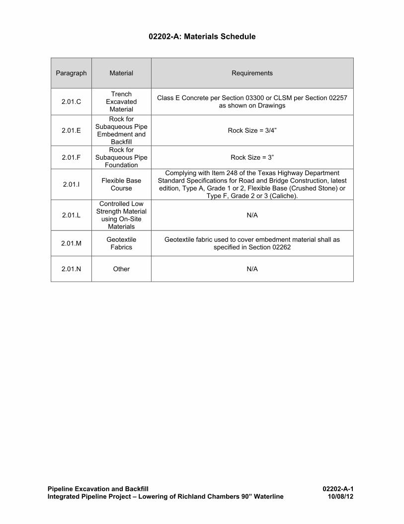
A. LEAN CONCRETE EMBEDMENT AND CAP
1. Where lean concrete embedment or cap is indicated or requested by the Engineer, it shall be Class E as defined in Section 03300 – CAST-IN-PLACE CONCRETE, unless otherwise indicated.
B. GRANULAR EMBEDMENT
1. Granular embedment material shall be sandy gravel or blended sand and crushed rock, or recycled crushed concrete free from large stones, clay, and organic material. Embedment material shall be a soil classification of GW, GP, SW, or SP as determined
Pipeline Excavation and Backfill 02202-4 Integrated Pipeline Project – Lowering of Richland Chambers 90” Waterline 10/08/12
by ASTM D2487. The embedment material shall be such that when wet, the fine material shall not form mud or muck or be dispersive. The embedment material shall be composed of tough durable particles, reasonably free from thin, flat and elongated pieces, sharp edges, and of suitable quality to insure permanence in the trench and have a percentage of wear of not more than 40% when tested in accordance with ASTM C131 or ASTM C535. The Plasticity Index of the fines shall not exceed 3. Light weight aggregate that weighs less than 80 pcf is not acceptable for granular embedment. Material used for granular embedment shall have a resistivity of not less than 5000 ohms/cm as measured by ASTM G57.
2. Granular embedment shall be cohesionless material meeting the following gradation requirements:
1. This material shall be as specified in Schedule 02202-A. Schedule is included on page 02202-A-1 immediately following the words END OF SECTION and shall be part of this Section.
D. COARSE GRAVEL
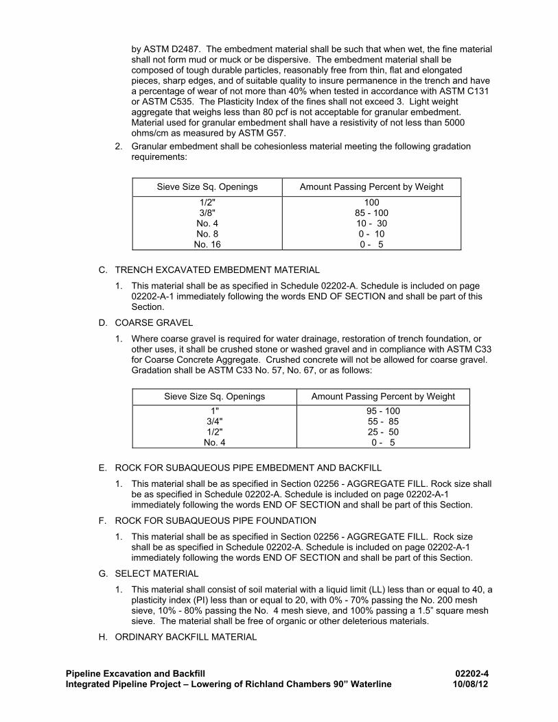
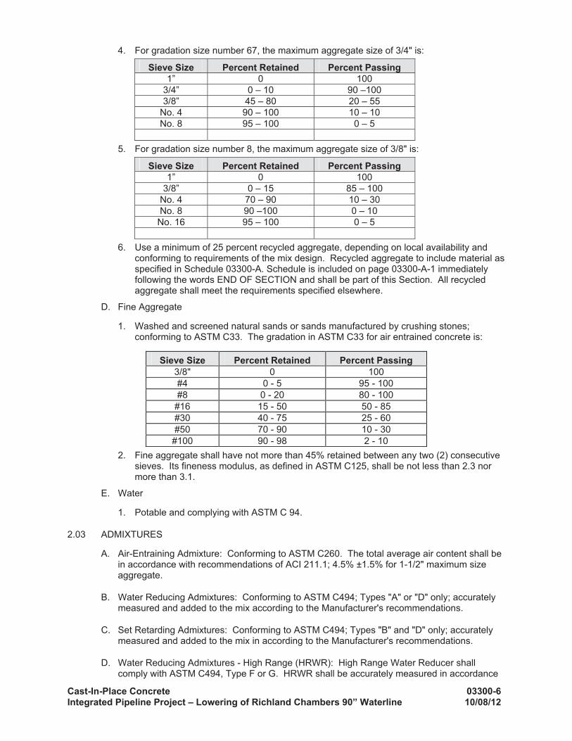
1. Where coarse gravel is required for water drainage, restoration of trench foundation, or other uses, it shall be crushed stone or washed gravel and in compliance with ASTM C33 for Coarse Concrete Aggregate. Crushed concrete will not be allowed for coarse gravel. Gradation shall be ASTM C33 No. 57, No. 67, or as follows:
Sieve Size Sq. Openings Amount Passing Percent by Weight
1" 3/4" 1/2"
No. 4
95 - 100 55 - 85 25 - 50 0 - 5
E. ROCK FOR SUBAQUEOUS PIPE EMBEDMENT AND BACKFILL
1. This material shall be as specified in Section 02256 - AGGREGATE FILL. Rock size shall be as specified in Schedule 02202-A. Schedule is included on page 02202-A-1 immediately following the words END OF SECTION and shall be part of this Section.
F. ROCK FOR SUBAQUEOUS PIPE FOUNDATION
1. This material shall be as specified in Section 02256 - AGGREGATE FILL. Rock size shall be as specified in Schedule 02202-A. Schedule is included on page 02202-A-1 immediately following the words END OF SECTION and shall be part of this Section.
G. SELECT MATERIAL
1. This material shall consist of soil material with a liquid limit (LL) less than or equal to 40, a plasticity index (PI) less than or equal to 20, with 0% - 70% passing the No. 200 mesh sieve, 10% - 80% passing the No. 4 mesh sieve, and 100% passing a 1.5” square mesh sieve. The material shall be free of organic or other deleterious materials.
H. ORDINARY BACKFILL MATERIAL
Pipeline Excavation and Backfill 02202-5 Integrated Pipeline Project – Lowering of Richland Chambers 90” Waterline 10/08/12
1. Trench excavated material free from rock fragments and clods larger than 6" greatest dimension. The ordinary material shall be free from organic materials.
I. FLEXIBLE BASE COURSE
1. This material shall be as specified in Schedule 02202-A. Schedule is included on page 02202-A-1 immediately following the words END OF SECTION and shall be part of this Section.
J. HOT MIX ASPHALT CONCRETE (HMAC)
1. HMAC shall be as specified in Section 02513 - HOT MIX ASPHALT CONCRETE.
K. FLOWABLE FILL
1. Flowable fill shall be as specified in Section 02257 - CONTROLLED LOW STRENGTH MATERIAL.
L. CONTROLLED LOW STRENGTH MATERIAL USING ON-SITE MATERIALS
1. This material shall be as specified in Schedule 02202-A. Schedule is included on page 02202-A-1 immediately following the words END OF SECTION and shall be part of this Section.
M. GEOTEXTILE FABRIC
1. This material shall be as specified in Schedule 02202-A. Schedule is included on page 02202-A-1 immediately following the words END OF SECTION and shall be part of this Section.
N. OTHER
1. This material shall be as specified in Schedule 02202-A. Schedule is included on page 02202-A-1 immediately following the words END OF SECTION and shall be part of this Section.
3.00 EXECUTION
3.01 CLEARING AND GRUBBING
A. Coordinate tree removal with the Owner. All trees to be removed shall be marked with flagging or spray-paint for review. No trees shall be removed in US Army Corps of Engineers (USACE) Property, city parks, or residential land, or outside the permanent easement indicated without prior approval of the Engineer. See the Drawings for additional limitations on tree removal.
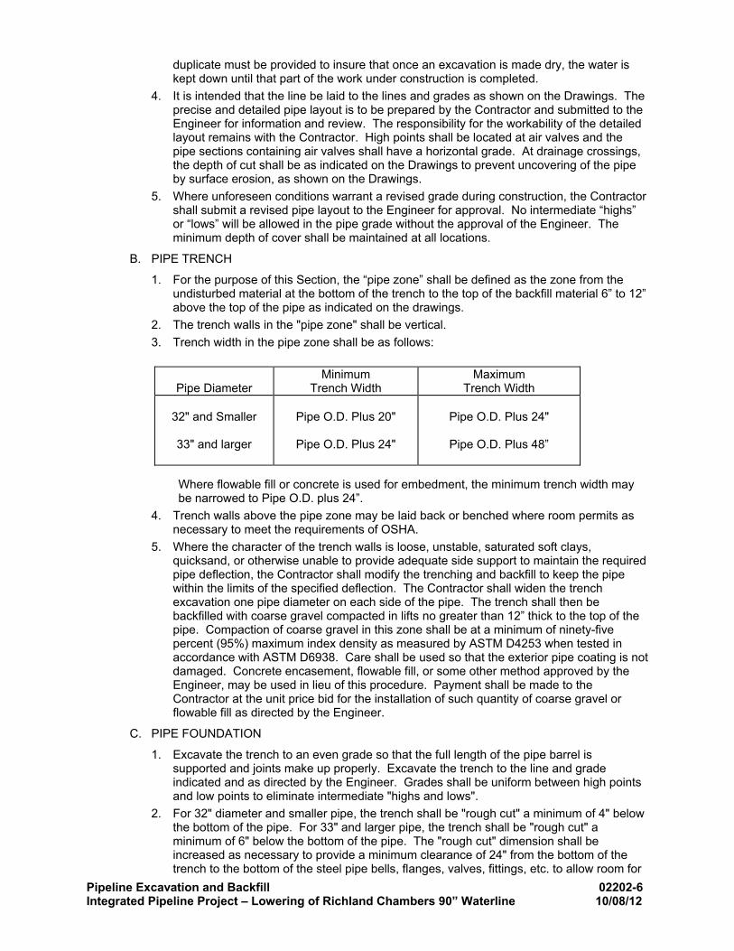
3.02 TRENCH EXCAVATION
A. GENERAL
1. Excavate trenches to the alignment, width, and depth as indicated or as required for the proper installation of the pipe. Brace the trench and/or dewater the trench if necessary so that the workmen may work safely and efficiently.
2. Comply with all applicable laws, ordinances, rules, regulations and orders of any public body having jurisdiction for the safety of persons or property or to protect them from damage, injury or loss. Comply with the requirements of Section 02220 - TRENCH SAFETY.
3. Prepare and submit a dewatering plan meeting the following requirements. Dewater excavations so that the work is performed in the "dry". Bailing, pumping, and dewatering shall be at the Contractor's expense. Use coarse gravel instead of embedment material under the pipe at no extra cost to the Owner to provide for the free drainage and flow of water in the pipe trench, where it is necessary, in order to keep the water level below the pipe barrel and bell holes for joints. The water removed from trenches shall be conducted to natural drainage ways, drains, or storm sewers in such a manner as to prevent damage to adjacent property or to the public. Pumps of ample capacity and in
Pipeline Excavation and Backfill 02202-6 Integrated Pipeline Project – Lowering of Richland Chambers 90” Waterline 10/08/12
duplicate must be provided to insure that once an excavation is made dry, the water is kept down until that part of the work under construction is completed.
4. It is intended that the line be laid to the lines and grades as shown on the Drawings. The precise and detailed pipe layout is to be prepared by the Contractor and submitted to the Engineer for information and review. The responsibility for the workability of the detailed layout remains with the Contractor. High points shall be located at air valves and the pipe sections containing air valves shall have a horizontal grade. At drainage crossings, the depth of cut shall be as indicated on the Drawings to prevent uncovering of the pipe by surface erosion, as shown on the Drawings.
5. Where unforeseen conditions warrant a revised grade during construction, the Contractor shall submit a revised pipe layout to the Engineer for approval. No intermediate “highs” or “lows” will be allowed in the pipe grade without the approval of the Engineer. The minimum depth of cover shall be maintained at all locations.
B. PIPE TRENCH
1. For the purpose of this Section, the “pipe zone” shall be defined as the zone from the undisturbed material at the bottom of the trench to the top of the backfill material 6” to 12” above the top of the pipe as indicated on the drawings.
2. The trench walls in the "pipe zone" shall be vertical. 3. Trench width in the pipe zone shall be as follows:
Pipe Diameter Minimum
Trench Width Maximum
Trench Width
32" and Smaller
33" and larger
Pipe O.D. Plus 20"
Pipe O.D. Plus 24"
Pipe O.D. Plus 24"
Pipe O.D. Plus 48”
Where flowable fill or concrete is used for embedment, the minimum trench width may be narrowed to Pipe O.D. plus 24”.
4. Trench walls above the pipe zone may be laid back or benched where room permits as necessary to meet the requirements of OSHA.
5. Where the character of the trench walls is loose, unstable, saturated soft clays, quicksand, or otherwise unable to provide adequate side support to maintain the required pipe deflection, the Contractor shall modify the trenching and backfill to keep the pipe within the limits of the specified deflection. The Contractor shall widen the trench excavation one pipe diameter on each side of the pipe. The trench shall then be backfilled with coarse gravel compacted in lifts no greater than 12” thick to the top of the pipe. Compaction of coarse gravel in this zone shall be at a minimum of ninety-five percent (95%) maximum index density as measured by ASTM D4253 when tested in accordance with ASTM D6938. Care shall be used so that the exterior pipe coating is not damaged. Concrete encasement, flowable fill, or some other method approved by the Engineer, may be used in lieu of this procedure. Payment shall be made to the Contractor at the unit price bid for the installation of such quantity of coarse gravel or flowable fill as directed by the Engineer.
C. PIPE FOUNDATION
1. Excavate the trench to an even grade so that the full length of the pipe barrel is supported and joints make up properly. Excavate the trench to the line and grade indicated and as directed by the Engineer. Grades shall be uniform between high points and low points to eliminate intermediate "highs and lows".
2. For 32" diameter and smaller pipe, the trench shall be "rough cut" a minimum of 4" below the bottom of the pipe. For 33" and larger pipe, the trench shall be "rough cut" a minimum of 6" below the bottom of the pipe. The "rough cut" dimension shall be increased as necessary to provide a minimum clearance of 24" from the bottom of the trench to the bottom of the steel pipe bells, flanges, valves, fittings, etc. to allow room for
Pipeline Excavation and Backfill 02202-7 Integrated Pipeline Project – Lowering of Richland Chambers 90” Waterline 10/08/12
installation of heat shrink sleeve, wax tape wrap, or other joint protection. Provide a sloped transition area to avoid abrupt changes in excavated trench bottom.
3. The entire foundation area in the bottom of all excavations shall be firm, stable material. Provide a sloped transition area in between excavation under the bell and excavation under the pipe to avoid abrupt changes in excavated trench bottom. Loose material shall be removed, leaving a clean, flat trench bottom, and material shall not be disturbed below required sub-grade except as hereinafter described. If the subgrade is soft, spongy, disintegrated, or where the character of the foundation materials is such that a proper foundation cannot be obtained at the elevation specified, then when directed by the Engineer the Contractor shall deepen the excavation to a depth where a satisfactory foundation can be obtained. The sub-grade shall then be brought back to the required grade with coarse gravel. Compaction of coarse gravel shall be at a minimum of ninety-five percent (95%) maximum index density as measured by ASTM D4253 when tested in accordance with ASTM D6938. Payment shall be made to the Contractor at the unit price bid for the installation of such quantity of coarse gravel as directed by the Engineer.
D. CORRECTING FAULTY GRADE
1. If the trench is excavated to a faulty grade (at a lower elevation than indicated), correct the faulty grade as specified below: a. In uniform, stable dry soils, correct the faulty grade with granular embedment material
thoroughly compacted to 95% of maximum density. b. In soft spongy disintegrated soils or where necessary to allow proper drainage,
correct the faulty grade with coarse gravel compacted to 95% of maximum density. Coarse gravel shall be surrounded by geotextile fabric.
c. No extra payment will be made for coarse gravel or other material to correct faulty grade.
E. PIPE CLEARANCE IN ROCK
1. Remove ledge rock, rock fragments, or unyielding shale or marl to provide a clearance of at least 6" below the pipe. Provide 24" clearance for properly jointing pipe laid in rock trenches at steel pipe joints, flanges, valves, fittings, etc. to allow room for installation of heat shrink sleeve, wax tape wrap, or joint protection. Employ a sloped transition area to avoid abrupt changes in excavated trench bottom. Refill the excavation to grade with embedment material.
F. BLASTING PROCEDURE
1. Blasting will not be allowed.
G. BELL HOLES REQUIRED
1. Bell holes of at least 24” dimension shall be dug in trenches at each heat shrink sleeve joint of pipe to permit the jointing to be made properly, visually inspected, and so that the pipe will rest on the full length of the barrel. Bell hole shall be 24” perpendicular and 24” parallel to the pipe. Pipe with field-applied exterior mortar coatings shall have the joints excavated to a sufficient depth to allow proper cleaning, application, testing and inspection of field applied coating system.
H. CARE OF SURFACE MATERIAL FOR REUSE
1. Surface materials such as top soil in its natural state, suitable for reuse in restoring the excavated surface, shall be kept separate from the general excavation material. The top 12" of the trench backfill shall be topsoil. Where mounding is allowed, excavate enough topsoil to completely cover the mound with 12 inches of topsoil. Where the natural topsoil is less than 12” deep, and with the approval of the Engineer, the Contractor may strip less than 12” of topsoil. In cultivated fields, the top 24” of the topsoil shall be stockpiled and placed as backfill.
Pipeline Excavation and Backfill 02202-8 Integrated Pipeline Project – Lowering of Richland Chambers 90” Waterline 10/08/12
2. The Contractor shall employ methods to prevent rock or gravel from mixing with the topsoil. If the topsoil is mixed with rock or gravel, the Engineer will direct the Contractor to replace the topsoil with imported topsoil from an approved source at contractor’s expense.
I. MANNER OF PILING EXCAVATED MATERIAL
1. Place excavated material so that work is not endangered or interferes with public traffic or other construction. Do not place excavated material over buried pipelines adjacent to excavations or existing utilities unless adequate provisions are made to protect those pipelines and/or utilities. Roads and driveways must be kept open in every case. Keep drainage channels clear of obstructions or make other satisfactory provisions for drainage.
J. TRENCHING BY MACHINE OR BY HAND
1. The use of trench digging machinery is approved except in places where operations of same will cause damage to existing structures or pipelines above or below ground, in which case employ hand methods.
K. OPEN TRENCH
1. Engineer shall have the right to limit the amount of trench which may be opened or partially opened at any time in advance of the completed line; and shall also have the right to limit the amount of trench left not backfilled. No more than 500' of trench in open country or pasture land shall be opened at any one time, and no more than 150' of trench in populated areas shall be left open unless otherwise permitted in writing by the Owner. In open country or pasture land with substantial rock, not over 1,500’ of trench shall be opened at any one time. Backfill and/or protect trenches as necessary to prevent injury to livestock, adjacent property, and the public. Trenches left open overnight in public areas shall be fenced with adequate construction fencing. No trenches shall be left open overnight in streets.
L. STRUCTURAL EXCAVATION
1. Excavation shall extend a sufficient distance from walls and footings to allow for form installation and inspection, except where concrete for walls and footings is authorized or required to be deposited directly against excavated surfaces. Where excavation, through the fault of the Contractor, is made below the elevation specified or directed by the Engineer, restore the excavation to the proper elevation with lean concrete or other approved material at the Contractor's expense.
3.03 BACKFILLING OF TRENCHES OUTSIDE ROADWAYS
A. GENERAL
1. This section is intended to cover the requirements for trench backfill where trench is in open fields, unimproved alleys, fields, and other similar open areas outside of existing or proposed public and private roadways.
B. TIME AND METHOD OF BACKFILLING
1. Backfill operations shall immediately follow pipe jointing, joint coating application, and curing. Backfilling method shall be heavy vibrating plates or large compaction wheels mounted on an excavator. Hand held compaction equipment will not be allowed.
C. BRACED AND SHEETED TRENCHES
1. Remove sheeting and shoring as backfilling operations progress. Incorporate methods so that a good bond is obtained between the backfill material and the undisturbed trench walls.
D. PROTECTION OF PIPE DURING BACKFILLING OPERATIONS
1. Take the necessary precautions to protect the pipe during backfilling operations. Take care to prevent damage to the pipe or to the pipe coating, and repair any damaged pipe before being "covered up". Backfill the trench to prevent the deformation or otherwise
Pipeline Excavation and Backfill 02202-9 Integrated Pipeline Project – Lowering of Richland Chambers 90” Waterline 10/08/12
deflection of the cylindrical shape of the pipe by more than 2/3 of the allowable pipe deflection as specified elsewhere. Stulling of steel pipe shall be used as depicted in the Drawings. Stulling shall meet or exceed standards listed in ASCE MOP No. 79.
E. SITE AND PREPARATION
1. In addition to clearing and grubbing of brush and trees along the right-of-way for this project, alteration to the topography shall be done if indicated on the Drawings, at the locations and to the extent shown.
F. BACKFILL PROCEDURE IN THE PIPE ZONE – STEEL PIPE
1. DEPTH OF COVER 5 TO 18 FEET (STEEL PIPE OPTION A – GRANULAR EMBEDMENT MATERIAL) a. Place the first lift of granular embedment material to a depth slightly above the
bottom of pipe grade. Lay pipe on this material to the indicated grade. Provide bell holes to permit the pipe to rest on the full length of the barrel and to permit joint make-up and coating.
b. Place the second lift of granular embedment material uniformly on both sides of the pipe to a depth of 0.25 times the outside diameter of the pipe, or 24-inches, whichever is smaller, taking precautions not to disturb the pipe alignment. Compact the second lift of embedment material using vibration or mechanical tamping. Contractor shall take precautions to ensure no voids occur under the haunches of the pipe and to prevent disturbance of the pipe alignment. Compaction of granular embedment in this zone shall be at a minimum of ninety-five percent (95%) maximum index density as measured by ASTM D4253 when tested in accordance with ASTM D6938 and ASTM D1556.
c. Place the subsequent lift of granular embedment material in the trench simultaneously and evenly on both sides of the pipe for the full width of the trench to a depth of 0.5 times the outside diameter of the pipe or 24-inches above the previous lift, whichever is smaller. Compact the embedment material using vibration or mechanical tamping. Compaction of granular embedment in this zone shall be at a minimum of ninety-five percent (95%) maximum index density as measured by ASTM D4253 when tested in accordance with ASTM D6938 and ASTM D1556.
d. Place the subsequent lift of granular embedment material in the trench simultaneously and evenly on both sides of the pipe for the full width of the trench to a depth of 0.7 times the outside diameter of the pipe or 24-inches above the previous lift, whichever is smaller. Compact the embedment material using vibration or mechanical tamping. Compaction of granular embedment in this zone shall be at a minimum of ninety-five percent (95%) maximum index density as measured by ASTM D4253 when tested in accordance with ASTM D6938 and ASTM D1556.
e. After placement and compaction of additional lifts (not greater than 24-inches depth) of the granular embedment material to a depth of 0.7 times the outside diameter, place select material, or alternate material as approved by the Engineer, simultaneously and evenly on both sides of the pipe for the full width of the trench in 12-inch lifts up to the top of the pipe zone. Compaction of select material in this zone shall be to a minimum of ninety-five percent (95%) of Standard Proctor Density. It is the responsibility of the Contractor to ensure the pipe is not subjected to excessive stress during backfill.
2. DEPTH OF COVER 5 TO 18 FEET (STEEL PIPE OPTION B - FLOWABLE FILL) a. Place the first lift of granular embedment material to a depth slightly above the
bottom of pipe grade. Lay pipe on this material to the indicated grade. Provide bell holes to permit the pipe to rest on the full length of the barrel and to permit joint make-up and coating.
b. Above the first lift of granular embedment, place flowable fill backfill in the trench simultaneously and evenly on both sides of the pipe for the full width of the trench to a depth of 0.7 times the outside diameter of the pipe. Place the flowable fill in multiple lifts as needed to prevent flotation of the pipeline. It is the responsibility of the Contractor to ensure that flotation of the pipe does not occur.
Pipeline Excavation and Backfill 02202-10 Integrated Pipeline Project – Lowering of Richland Chambers 90” Waterline 10/08/12
c. After placement and compaction of the flowable fill material to a depth of 0.7 times the outside diameter, and after allowing enough time for the flowable fill to set up, place select material simultaneously and evenly on both sides of the pipe for the full width of the trench in 12-inch lifts up to the top of the pipe zone. Compaction of select material in this zone shall be to a minimum of ninety-five percent (95%) of Standard Proctor Density. Be careful not to put excessive load directly over the pipe.
3. DEPTH OF COVER OVER 18 FEET (STEEL PIPE OPTION C – FLOWABLE FILL 6” ABOVE TOP) a. Where the depth of cover exceeds 18 feet, or where indicated, backfill the pipe trench
with flowable fill to 6” above the top of the pipe in accordance with Section 02257 - FLOWABLE FILL. Pipe shall be blocked up on sack-crete in burlap bags to allow a minimum of 6” of flowable fill below the pipe. The Contractor shall perform backfilling in a manner to prevent dislocating or floating the pipe
b. The Contractor may place flowable fill in two stages, allowing sufficient time for the initial stage to set. If two stages are used, the Contractor shall protect the surface of the lower stage from soil and water, so that a good bond is achieved between the stages. Care should be exercised during depositing and compaction of the flowable fill so as to form a compact, dense, impervious mass free of voids.
4. DEPTH OF COVER 5 TO 18 FEET (STEEL PIPE – MODIFIED NATIVE MATERIAL EMBEDMENT OPTION) a. Follow procedures indicated in Schedule 02202-B. Schedule is included on page
02202-A-2 immediately following the words END OF SECTION and shall be part of this Section.
5. SPECIAL REQUIREMENT FOR WELD AFTER BACKFILL a. See Section 02626 – STEEL PIPE for special requirements for joint backfill for weld
after backfill.
G. BACKFILL PROCEDURE IN THE PIPE ZONE - PCCP
1. DEPTH OF COVER 4 TO 18 FEET (PCCP OPTION A – GRANULAR EMBEDMENT MATERIAL) a. Place the first lift of granular embedment material to a depth slightly above the
bottom of pipe grade. Lay pipe on this material to the indicated grade. Provide bell holes to permit the pipe to rest on the full length of the barrel and to permit joint make-up and coating.
b. Place the second lift of granular embedment material uniformly on both sides of the pipe to a depth of 0.20 times the outside diameter of the pipe, or 24-inches, whichever is smaller, taking precautions not to disturb the pipe alignment. Compact the second lift of embedment material using vibration or mechanical tamping. Contractor shall take precautions to ensure no voids occur under the haunches of the pipe and to prevent disturbance of the pipe alignment. Compaction of granular embedment in this zone shall be at a minimum of ninety-five percent (95%) maximum index density as measured by ASTM D4253 when tested in accordance with ASTM D6938 and ASTM D1556.
c. Place the subsequent lift of granular embedment material in the trench simultaneously and evenly on both sides of the pipe for the full width of the trench to a depth of 0.4 times the outside diameter of the pipe or 24-inches above the previous lift, whichever is smaller. Compact the embedment material using vibration or mechanical tamping. Compaction of granular embedment in this zone shall be at a minimum of ninety-five percent (95%) maximum index density as measured by ASTM D4253 when tested in accordance with ASTM D6938 and ASTM D1556.
d. After placement and compaction of additional lifts (not greater than 24-inches depth) of the granular embedment material to a depth of 0.4 times the outside diameter, place select material simultaneously and evenly on both sides of the pipe for the full width of the trench in 12-inch lifts up to the top of the pipe zone. Compaction of select material in this zone shall be to a minimum of ninety-five percent (95%) of Standard Proctor Density. Be careful not to put excessive load directly over the pipe.
Pipeline Excavation and Backfill 02202-11 Integrated Pipeline Project – Lowering of Richland Chambers 90” Waterline 10/08/12
2. DEPTH OF COVER 4 TO 18 FEET (PCCP OPTION B - FLOWABLE FILL) a. Place the first lift of granular embedment material to a depth slightly above the
bottom of pipe grade. Lay pipe on this material to the indicated grade. Provide bell holes to permit the pipe to rest on the full length of the barrel and to permit joint make-up and coating.
b. Above the first lift of granular embedment, place flowable fill backfill in the trench simultaneously and evenly on both sides of the pipe for the full width of the trench to a depth of 0.4 times the outside diameter of the pipe. Place the flowable fill in multiple lifts as needed to prevent flotation of the pipeline. It is the responsibility of the Contractor to ensure that flotation of the pipe does not occur.
c. After placement and compaction of the flowable fill material to a depth of 0.4 times the outside diameter, and after allowing enough time for the flowable fill to set up, place select material simultaneously and evenly on both sides of the pipe for the full width of the trench in 12-inch lifts up to the top of the pipe zone. Compaction of select material in this zone shall be to a minimum of ninety-five percent (95%) of Standard Proctor Density. Be careful not to put excessive load directly over the pipe.
3. DEPTH OF COVER OVER 18 FEET (PCCP OPTION C - FLOWABLE FILL 6” ABOVE TOP) a. Where the depth of cover exceeds 18 feet, or where indicated, backfill the pipe trench
with flowable fill to 6” above the top of the pipe in accordance with Section 02257 - FLOWABLE FILL. Pipe shall be blocked up on sack-crete in burlap bags to allow a minimum of 6” of flowable fill below the pipe. The Contractor shall perform backfilling in a manner to prevent dislocating or floating the pipe
b. The Contractor may place flowable fill in two stages, allowing sufficient time for the initial stage to set. If two stages are used, the Contractor shall protect the surface of the lower stage from soil and water, so that a good bond is achieved between the stages. Care should be exercised during depositing and compaction of the flowable fill so as to form a compact, dense, impervious mass free of voids.
4. DEPTH OF COVER 5 TO 18 FEET (PCCP – MODIFIED NATIVE MATERIAL EMBEDMENT OPTION) a. Follow procedures indicated in Schedule 02202-B. Schedule is included on page
02202-A-2 immediately following the words END OF SECTION and shall be part of this Section.
5. SPECIAL REQUIREMENTS FOR RESTRAINED PCCP PIPE AND FITTINGS a. Where PCCP is restrained for thrust, the granular embedment material shall be
placed in lifts not exceeding two feet up to 0.7 times the pipe O.D. Fittings, including but not limited to bends, tees, plugs, and wyes and adjacent pipe joints, shall be completely encased in flowable fill up to 6 inches over the top of the pipe. The encased length along the centerline shall include at a minimum the full length of the fitting and 16 feet each side of the end of the fitting.
H. BACKFILL PROCEDURE ABOVE PIPE ZONE
1. Mechanical compaction shall be utilized. Hand held mechanical compaction equipment will not be allowed, except in special locations such as fittings and near structures. Place the ordinary backfill material per Section 2.01.H, or alternate material as approved by the Engineer, above the pipe zone in lifts not exceeding 18 inches loose depth and compacted to 90% or 95% Standard Proctor density, as designated in the Drawings. The Contractor shall be responsible for any damage which may occur to the pipe using his method of compaction.
2. Where indicated on the Drawings backfill the trench with lean concrete or flowable fill as indicated.
I. SURFACE MATERIAL REPLACEMENT
1. The top 12 inches of the backfill (and 24 inches in cultivated property) shall be composed of the original surface material or topsoil excavated from the trench. Grade the surface to allow drainage in the same manner as existed prior to construction.
Pipeline Excavation and Backfill 02202-12 Integrated Pipeline Project – Lowering of Richland Chambers 90” Waterline 10/08/12
2. In open rural areas other than cultivated property, excess material may be spread out over the easement to the dimensions shown on the Drawings. The mound shall be completely covered with 12 inches of topsoil. Grade the surface to allow drainage in the same manner as existed prior to construction.
3. Topsoil shall be of the same general type and fully compatible with that in undisturbed immediately adjacent areas. Topsoil shall not contain rocks or clods larger than those adjacent to the trench in the undisturbed condition. In parks, residential areas, crop land, and commercial lawn areas, remove all rocks, clods, debris, and trash from topsoil.
J. BACKFILL AROUND STRUCTURES
1. After completion of foundations, walls, etc., remove forms and clean excavation of debris or other objectionable matter prior to placing backfill. Comply with the requirements of Section 02221 – STRUCTURAL EXCAVATION AND BACKFILL for backfill adjacent to cast-in-place structures.
2. In areas where structures such as slabs, foundations, or pipes are to be constructed on backfill, backfill shall be lean concrete or flowable fill, unless otherwise indicated.
3. In areas where excavation for pipe exceeds the maximum allowable trench width, backfill in the pipe zone with flowable fill.
4. For pre-cast concrete structures, mechanically tamp earth backfill around and over structures, using select material, and placed in layers not to exceed 8 inches, loose thickness. Bring material to within 2% of optimum moisture content and compact each layer to a uniform density of not less than 95% of maximum density as determined by ASTM D698. Laboratory control shall be used to secure compliance with this requirement.
K. INSPECTION AND TEST PITS
1. Excavate test pits after the embedment has been placed and compacted in the pipe zone for the purpose of taking field density tests and inspecting the haunch areas under the pipe for voids.
2. Excavate the test pits to a depth and area of sufficient size to allow the inspector to visually inspect the haunch area of the pipe for voids or loose material next to the pipe and to make a field density test. Provide a safety trench shield to protect the inspector while in the pit.
3. After inspection, backfill and compact the test pit area in accordance with the applicable part of this Section.
4. Dig one (1) test pit for inspection of each day’s work if deemed necessary or may be required more or less frequently as determined by the Owner. Repair and replace areas which are found not to be in compliance with the requirements of this Section, until satisfactory results are consistently and uniformly attained.
5. Provide special attention to assure that the material flows under the pipe haunches. This may require the removal of pipe joints to observe the results and make density tests. Pipe laying shall not begin until satisfactory results are achieved by the Contractor’s proposed method.
3.04 BACKFILL PROCEDURE FOR PUBLIC AND PRIVATE ROADS
A. Improved Roads: Trench excavation, pipe laying, and backfill within the pipe zone and other general requirements shall be as indicated for trenches outside roadways except that flowable fill shall be placed to the top of the pipe zone per Option C described in this Section, Paragraphs 3.03.F.3 and 3.03.G.3. Backfill material above the pipe zone for existing roads including City Roads, County Roads, paved or improved private roads, driveways, and any proposed roads as indicated shall consist of granular embedment material for the full depth of the trench to subgrade. Compaction of the granular embedment shall be at a minimum of ninety-five percent (95%) maximum index density as measured by ASTM D4253 when tested in accordance with ASTM D6938 and ASTM D1556. Replace flexbase, asphalt, and concrete pavement according to the details in the Drawings and to Section 02314 –
Pipeline Excavation and Backfill 02202-13 Integrated Pipeline Project – Lowering of Richland Chambers 90” Waterline 10/08/12
PIPELINE CROSSING HIGHWAYS, STREETS, AND R.R.’S BY TUNNELING OR OPEN CUT.
B. Unimproved Field Roads: Trench excavation, pipe laying, and backfill within the pipe zone and other general requirements shall be as indicated for trenches outside roadways Option A described in this Section, Paragraphs 3.03.F.1 and 3.03.G.1, except compact the top 12 inches to 95% Standard Proctor Density.
3.05 TRENCH EXCAVATION, EMBEDMENT AND BACKFILL PROCEDURES FOR SUBAQUEOUS PIPE AT LAKE OUTFALLS
A. TRENCH EXCAVATION
1. For water less than 8-foot in depth, the Contractor may place temporary fill in the lake and excavate the trench per typical trenching methods. The amount of fill placed in the lake shall not exceed the fill quantity shown on the Drawings. After placement of the pipe, all fill must be removed to the pre-existing lake contours.
2. For water deeper than 8-foot in depth, excavate the pipe trench to the alignment, width, and depth as indicated on the Drawings by means of mechanical dredging. The trench width shall be as shown in the Drawings. Correct faulty grade (at a lower elevation than indicated) with 3-inch rock.
B. DISPOSAL OF EXCAVATED MATERIAL
1. Excavated material may not be side-cast into the lake. 2. Excavated material shall be placed on a barge and taken to shore. The barge shall be
lined with geotextile to prevent sediment from running off into the water. The material may be dewatered at the site shown on the Drawings. After the material has dried, the material may be placed in the area shown on the Drawings and as directed by the Owner.
C. PIPE FOUNDATION
1. Excavate the trench to an even grade so that the full length of pipe barrel is supported and joints up properly. Excavate the trench to the line and grade indicated and as determined by the Engineer. Grades shall be uniform between high points and low points to eliminate intermediate high and low points.
2. Place a one foot thick layer of pipe foundation rock on the trench bottom to provide a firm stable foundation for the pipe.
3. Provide access for divers to verify rock foundation.
D. EMBEDMENT AND BACKFILLING
1. Place a first lift of embedment rock to a depth slightly above the bottom of the pipe grade. Lay pipe on this material to the indicated grade. Provide bell holes to permit the pipe to rest on the full length of the barrel and to permit joint make-up.
2. Place the second lift of embedment rock material uniformly on both sides of the pipe to a depth of 0.25 times the outside diameter of the pipe, taking precautions not to disturb the pipe alignment. Contractor shall take precautions to ensure no voids occur under the haunches of the pipe and to prevent disturbance of the pipe alignment.
3. Place the third lift of embedment rock material in the trench simultaneously and evenly on both sides of the pipe for the full width of the trench to the top of the pipe.
4. Place a fourth lift of backfill rock in the trench to within 2 feet of the final grade of the lake bottom.
5. Place a final layer of 2-foot thick rock rip-rap to the grade of the original lake bottom. See Drawings for rip-rap gradation.
3.06 MAINTENANCE OF SURFACES
A. ROCK AND ORGANIC MATERIAL EXCLUSION
Pipeline Excavation and Backfill 02202-14 Integrated Pipeline Project – Lowering of Richland Chambers 90” Waterline 10/08/12
1. Rock and organic material removed from the trench excavated material shall be removed from the right-of-way at the Contractor's expense.
B. DEFICIENCY OF BACKFILL - BY WHOM SUPPLIED
1. Any deficiency in the quantity of material for backfilling the trenches or for filling depressions caused by settlement shall be supplied by the Contractor at his expense. Make-up material shall be approved by the Owner.
C. RESTORATION OF SURFACES
1. Replace surface material and restore paving, curbing, sidewalks, gutters, shrubbery, fences, grass or turf, and other surfaces disturbed, as nearly as possible to a condition equal to that before the work begin.
D. SEEDING AND SODDING
1. Provide seeding and sodding for all disturbed areas, except areas which receive paving, per Section 02270 - SEEDING FOR EROSION CONTROL.
3.07 CLEAN AND ADJUST
A. Remove surplus pipeline materials, tools, rubbish, trees, and temporary structures, and leave the construction site clean, to the satisfaction of the Engineer. Grade the surface, and re-establish drainage. Removal of rock and other excess excavated material and general leveling and grading of the right-of-way surface to a presentable appearance shall proceed so as to not be further than 2,500 feet behind the backfilling operations. The Contractor shall be responsible for location of sites for disposal of excess material and the Owner shall make no additional payment for expenses incurred in such disposal.
END OF SECTION
Pipeline Excavation and Backfill 02202-A-1 Integrated Pipeline Project – Lowering of Richland Chambers 90” Waterline 10/08/12
02202-A: Materials Schedule
Paragraph Material Requirements
2.01.C Trench
Excavated Material
Class E Concrete per Section 03300 or CLSM per Section 02257 as shown on Drawings
2.01.E
Rock for Subaqueous Pipe Embedment and
Backfill
Rock Size = 3/4”
2.01.F Rock for
Subaqueous Pipe Foundation
Rock Size = 3”
2.01.I Flexible Base Course
Complying with Item 248 of the Texas Highway Department Standard Specifications for Road and Bridge Construction, latest edition, Type A, Grade 1 or 2, Flexible Base (Crushed Stone) or
Type F, Grade 2 or 3 (Caliche).
2.01.L
Controlled Low Strength Material
using On-Site Materials
N/A
2.01.M Geotextile Fabrics
Geotextile fabric used to cover embedment material shall as specified in Section 02262
2.01.N Other N/A
Pipeline Excavation and Backfill 02202-A-2 Integrated Pipeline Project – Lowering of Richland Chambers 90” Waterline 10/08/12
02202-B: Backfill Procedure using Native Materials
Paragraph Pipe Material /Embedment
Material Option Backfill Procedure
3.02.F.4 Steel Pipe
Modified Native Material
Backfill Procedure in the Pipe Zone: N/A
3.02.G.4 PCCP
Modified Native Material
Backfill Procedure in the Pipe Zone: N/A
Trenching, Backfilling, and Pipe Embedment for Utility Lines 02217-1 Integrated Pipeline Project – Lowering of Richland Chambers 90” Waterline 10/08/12
02217 TRENCHING, BACKFILLING, AND PIPE EMBEDMENT FOR UTILITY LINES
1.00 GENERAL
1.01 WORK INCLUDED
A. This Section sets forth requirements for trenching, backfilling and embedment of storm drains, drain lines, waterlines 24-inch or smaller in diameter, sewer lines, miscellaneous utility relocations, and any work specifically directed by the Contract Documents to be performed in accordance with Section 02217 - TRENCHING, BACKFILLING, AND PIPE EMBEDMENT FOR UTILITY LINES.
B. Furnish labor, materials, equipments and incidentals necessary to perform operations in trenching, pipe bedding, backfilling, clearing, grubbing and site preparation; handling, storage, transportation and disposal of excavated material; pumping and dewatering; preparation of subgrades; protection of adjacent property; fills, grading; and other appurtenant work. Trenching, backfilling, and pipe embedment procedures shall be in full compliance with Section 02220 - TRENCH SAFETY. Earth removed from excavations, which is not required for backfill, shall be removed from the site by the Contractor at his own expense, unless arrangements are made with the Owner to allow disposal on site. If permitted, dump and spread excess earth in a manner agreed upon by the Contractor and the Owner. Excavation, other than trench excavation for utility lines as described above is not part of this Section.
1.02 QUALITY ASSURANCE
A. Classification
1. Excavations include material of whatever nature encountered, including but not limited to clays, sands, gravels, conglomeritic boulders, weathered clay shales, rock, debris and abandoned existing structures. Excavation and trenching include the removal and subsequent handling of materials excavated or otherwise handled in the performance of the work.
2. Bidders must satisfy themselves as to the actual existing subsurface conditions prior to the submittal of a proposal to complete the proposed work.
3. Trench excavation consists of excavation to the lines and grades indicated, required for installation of the pipe, pipe bedding, backfill, and to accommodate trench safety systems.
1.03 SUBMITTALS
A. Submittals shall be in accordance with Section 01300 - SUBMITTALS and shall include:
1. Sieve analysis on embedment materials as Shop Drawing. 2. Test results indicating soil resistivity for embedment material used on metal pipe as Shop
Drawing. 3. Dewatering Plan per requirements in Section 3.01.B as Record Data. A signed and
sealed Trench Dewatering Plan by an engineer registered in the State of Texas is required if a well point system is necessary.
1.04 STANDARDS
A. The following publications, referred to hereafter by basic designation only, form a part of this Section to the extent indicated by the references thereto:
ASTM D448 Standard Classification for Sizes of Aggregate for Road and Bridge Construction
ASTM D698 Standard Test Methods for Laboratory Compaction Characteristics of Soil Using Standard Effort (12 400 ft-lbf/ft3)
Trenching, Backfilling, and Pipe Embedment for Utility Lines 02217-2 Integrated Pipeline Project – Lowering of Richland Chambers 90” Waterline 10/08/12
ASTM D1556 Standard Test Method for Density and Unit Weight of Soil in Place by the Sand-Cone Method
ASTM D2487 Standard Practice for Classification of Soils for Engineering Purposes (Unified Soil Classification System)
ASTM D4253 Standard Test Methods for Maximum Index Density and Unit Weight of Soils Using a Vibratory Table
ASTM D4254 Standard Test Methods for Minimum Index Density and Unit Weight of Soils and Calculation of Relative Density
ASTM D6938 Standard Test Method for In-Place Density and Water Content of Soil and Soil-Aggregate by Nuclear Methods (Shallow Depth)
B. Any other testing required by the Contract Documents and not specifically referenced to a standard shall be performed under ASTM or other appropriate standards as designated by the Engineer.
C. Reference herein or on the Drawings to soil classifications shall be understood to be according to ASTM D2487, Classification of Soils for Engineering Purposes (Unified Soil Classification System).
1.05 DELIVERY AND STORAGE
A. Excavated materials to be used for backfill may be deposited in stockpiles at points convenient for re-handling the material during the backfilling process. The location of stockpiles must be within the limits of construction easements or public right-of-way. The location of stockpiles is subject to the approval of the Owner. Keep drainage channels clear of stockpiled materials.
1.06 JOB CONDITIONS
A. Place no embedment or backfill material during freezing weather or upon frozen subgrades or previously placed frozen embedment or backfill materials.
2.00 PRODUCTS
2.01 MATERIALS
A. CONCRETE FOR BACKFILL, BLOCKING, CRADLING AND ENCASEMENT: Unless other strength requirements are designated, concrete used shall be 1500 psi as specified in Section 03300 - CAST IN PLACE CONCRETE.
B. CLASS 1 EARTH FILL: As specified in Section 02255 – EARTH FILL CLASSIFICATIONS.
C. CLASS 3 EARTH FILL: As specified in Section 02255 – EARTH FILL CLASSIFICATIONS.
D. CLASS 12 EARTH FILL: As specified in Section 02255 – EARTH FILL CLASSIFICATIONS.
E. CLASS 2 AGGREGATE FILL:
Consist of durable particles of crushed stone free of silt, clay, or other unsuitable materials and have a percentage of wear of not more than 40% when tested in accordance with ASTM C131 or ASTM C535. When material is subjected to five (5) cycles of the sodium sulfate soundness test in accordance with ASTM C88, Sodium Sulfate Solution, the weighted percentage of loss shall not exceed 12%. The source of the material shall be approved by the Engineer and meet the following gradation in accordance with ASTM D448, size number 67:
Trenching, Backfilling, and Pipe Embedment for Utility Lines 02217-3 Integrated Pipeline Project – Lowering of Richland Chambers 90” Waterline 10/08/12
Sieve Size Square Opening Percent Passing 1"
3/4" 3/8"
No. 4 No. 8
100 90 - 100 20 - 55 0 - 10 0 - 5
F. CLASS 3 AGGREGATE FILL:
Consist of durable particles of crushed stone free of silt, clay, or other unsuitable materials and have a percentage of wear of not more than 40% when tested in accordance with ASTM C131 or ASTM C535. When material is subjected to five (5) cycles of the sodium sulfate soundness test in accordance with ASTM C88, Sodium Sulfate Solution, the weighted percentage of loss shall not exceed 12%. The source of the material shall be approved by the Engineer and meet the following gradation in accordance with ASTM D448, size number 7:
Sieve Size Square Opening Percent Passing
3/4" 1/2" 3/8"
No. 4 No. 8
100 90 - 100 40 - 70 0 - 15 0 - 5
G. CLASS 10 AGGREGATE FILL:
Consist of washed and screened natural sands or sands manufactured by crushing stones complying with the requirements and tests of Standard Specifications for Concrete Aggregates, ASTM C33. The gradation as included in ASTM C33 is as follows:
Class 10 Aggregate Fill shall have not more than 45% passing any sieve and retained on the next consecutive sieve of those shown above, and its fineness modulus, as defined in ASTM C125, shall be not less than 2.3 nor more than 3.1.
H. CEMENT: Type I Portland Cement.
I. FLOWABLE FILL: Flowable fill shall be in accordance with Section 02257 - CONTROLLED LOW-STRENGTH MATERIAL (FLOWABLE FILL)
J. UTILITY DETECTION TAPE: Install utility pipe detection tape, green in color for sewer, blue in color for water, with black nondegradable printing reading “CAUTION WATER LINE BURIED BELOW over all PVC, HDPE, or fiberglass utility lines 8-inches and larger. The tape must be bright-colored, continuous-printed, plasticized aluminum tape, intended for direct burial service; not less than 6-inches wide by 5 mils thick. Detection tape must be installed above the pipe zone, 12” above the pipe.
K. TRACER WIRE: Install all piping with a continuous, insulated TW, THW, THWN or HMWPE insulated copper, 10-gauge or thicker wire for utility line location purposes by means of an electronic line tracer. Install the wire along the entire length of pipe. Match the insulation
Trenching, Backfilling, and Pipe Embedment for Utility Lines 02217-4 Integrated Pipeline Project – Lowering of Richland Chambers 90” Waterline 10/08/12
color to the color of pipe being installed. Splice sections of wire together using approved splice caps and waterproof seals. Twisting the wires together is not acceptable.
3.00 EXECUTION
3.01 PREPARATION
A. SITE
1. Clear sites of logs, trees, roots, brush, tree trimmings and other objectionable materials and debris which are to be occupied by pipe trenches, and grub stumps. Designate material not salvaged for reuse as surface material as spoil and dispose of material in accordance with Paragraph 3.01.E of this Section.
2. Do not remove trees outside of the required working area unless their removal is authorized in writing by the Engineer and with the approval of the local governing authority. Adequately protect the trees left standing from permanent damage by construction operations. Standing trees may be trimmed where necessary to facilitate construction, but only with written authorization from the Engineer.
B. DEWATERING
1. Prepare and submit a trench dewatering plan to satisfy the requirements in this section. 2. Provide and maintain adequate dewatering equipment to remove and dispose of surface
and ground water entering the excavations, trenches, or other parts of the work. Keep each excavation dry during subgrade preparation and continually thereafter until the proposed pipe is installed. Maintain the proper procedures necessary to protect against damage to the proposed work from hydrostatic pressure, flotation, or other water related causes.
3. Dewater excavations which extend down to or below ground water elevation by lowering and keeping the ground water level a minimum of 2-feet below the bottom of the excavation.
4. Divert surface water or otherwise prevent water from entering excavated areas to the fullest extent possible without causing damage to adjacent property.
5. Provide and maintain any piping or conduit necessary to facilitate drainage. Do not alter area drainage patterns to the extent that adjacent property and landowners become threatened with localized flooding and/or water damage. Should such a situation occur, the Contractor shall be responsible for repairing the damage at no additional cost to the Owner.
C. PROTECTION OF EXISTING STRUCTURES AND UTILITIES
1. Prior to the start of construction, communicate with the local representatives of utilities companies, including but limited to oil, gas, telephone, and communications companies, as well as local water and sewer utilities operating in the location of the proposed construction area. Seek the utility companies assistance in locating existing facilities to avoid conflicts during construction. The location, number, depth, and owner of utilities indicated are for information purposes only, and all utilities and structures may not be shown or may not be in the location shown.
2. Where construction endangers adjacent structures, utilities, embankments and/or roadways, carefully support and protect such structures so that no damage occurs throughout the construction process. In case damage should occur, restore the damaged structure to a condition acceptable to the owner of that structure and bear all cost of such reparations.
3. Repair or replace damaged street surfaces, driveways, sidewalks, curbs, gutters, fences, drainage structures, or other such facilities to the satisfaction of the owner. Structures must be returned to a condition equal to or better than the original condition and of same or better material and quality.
D. BLASTING
Blasting shall not be allowed in any instance.
Trenching, Backfilling, and Pipe Embedment for Utility Lines 02217-5 Integrated Pipeline Project – Lowering of Richland Chambers 90” Waterline 10/08/12
E. DISPOSAL OF SPOIL MATERIAL
1. Suitable material from excavations which meets the requirements for pipe backfill material as indicated, except stripping excavation, may be reused. Designate the remaining excavated materials as spoiled material and dispose of material off the site in accordance with all applicable laws, ordinances, and codes. Contractor shall be responsible for the storage, transportation, and deposition of spoiled material and shall be responsible for acquiring the necessary permits, and the payment of fees and duties at no additional cost to the Owner.
2. No burning of materials is permitted on the site.
3.02 TRENCH EXCAVATION
A. GENERAL
Excavate trenches to the alignment and depth indicated or as necessary for the proper installation of the pipe and appurtenances. Brace and dewater the trench if necessary so that the workmen may work therein safely and efficiently. Any specific requirement listed in Part 3.00 EXECUTION may be modified as necessary to meet OSHA requirements. However, if trench widths are wider than indicated, the Contractor shall be responsible for determining and furnishing the proper class of embedment and piping for the installation with no additional compensation to the Contractor.
B. TRENCH WIDTH
Excavate trenches to a width of Pipe O.D. + 24” to Pipe O.D. + 48”.
C. PIPE FOUNDATION SUBGRADE
1. Excavate the trench to an even grade to permit the installation of the pipe so that the full length of the pipe barrel is supported on the proper depth of bedding material. Ensure the entire foundation subgrade area in the bottom of the excavation is firm, stable material, and the material below required grade is not disturbed except as described in this Section. Where the character of the subgrade material is such that proper subgrade cannot be obtained at the elevation indicated, deepen the excavation to a satisfactory subgrade material.
2. Remove the material until a firm, stable, and uniform bearing is reached and the subgrade brought back to the required grade with coarse gravel compacted in place or with lean concrete material. The expense of replacing any unsatisfactory subgrade will be paid for under the extra coarse gravel or concrete pay items.
D. CORRECTING FAULTY GRADE
Should any part of the trench be excavated below required grade, correct the trench with thoroughly compacted bedding material or lean concrete at no additional cost to the Owner.
E. CARE OF SURFACE MATERIAL FOR REUSE
If local conditions permit reuse, keep surface material suitable for reuse separate from the general excavation material.
F. TRENCHING METHODS
The use of any suitable trench digging machinery is permitted except in places where such operations may cause damage above or below ground, in which case, employ hand methods.
G. PIPE CLEARANCE IN ROCK
Remove ledge rock, rock fragments, shale, or other rock to provide proper clearance for bedding materials. Provide adequate clearance for properly jointing pipe laid in rock trenches at bell holes.
Trenching, Backfilling, and Pipe Embedment for Utility Lines 02217-6 Integrated Pipeline Project – Lowering of Richland Chambers 90” Waterline 10/08/12
3.03 BACKFILL
A. The Contractor shall backfill the pipe as provided in this Section to preclude floating of the placed pipe. Should floating occur, the Contractor shall remove and reinstall the pipe to a point beyond the area in question identified by the Engineer.
B. BEDDING WITHIN PIPE ZONE
1. FLOWABLE FILL – Where indicated, install the pipe in flowable fill. Take precautions to prevent pipe movement or deflection during construction. Where pipes are placed below structures, completely encase pipes in flowable fill and extend up to bottom of structure.
2. CONCRETE BLOCKING - Place blocking to rest against firm undisturbed trench walls. The supporting area for each block shall be at least as great as that indicated and be sufficient to withstand the thrust, including water hammer, which may develop. Each block shall rest on a firm undisturbed foundation of trench sides and bottom.
B. AGGREGATE FILL BEDDING AND EMBEDMENT
1. For Reinforced Concrete or Concrete Cylinder Pipe use Class 2 Aggregate. For Iron, Cast Iron, Ductile Iron, or Corrugated Metal Pipe use Class 3 Aggregate. For Non-reinforced Concrete, Vitrified Clay, PVC, or Fiberglass use Class 10 Aggregate.
2. After the trench has been cut to the depths indicated, bring up the bedding layer to a point slightly above grade in maximum 4" lifts and uniformly compact to the density indicated. Form bell holes and scoop out a trough to grade so that the pipe is uniformly supported by the embedment material. Lay and joint the pipe. Bring up the embedment material in maximum 4" lifts on either side of the pipe to the elevation above the pipe shown on the Drawings. Uniformly compact the pipe as indicated.
3. After moisture is gone from the embedment material, place and compact the remaining backfill by tamping or other appropriate methods. Water jetting shall not be permitted.
4. Provide Aggregate Fill for embedment material in the pipe zone (to 6” above the top of pipe). Provide Class 3 Earth Fill backfill above the pipe zone.
C. COMPACTION REQUIREMENTS
1. Compact earth fill and cohesive aggregate fill in maximum 4" lifts with pneumatic rollers or power hand tampers and make a minimum of eight (8) passes.
2. Compact cohesionless aggregate fill in maximum 4" lifts with vibratory rollers or vibratory plate power hand compactors and make a minimum of eight (8) passes.
3. The acceptability of the compaction equipment shall be based upon the results of a test Section.
4. Compact earth fill and cohesive aggregate fill to a minimum of 95% of maximum dry density as determined by ASTM D698, Standard Proctor.
5. Compact Class 1 and 2 earth fill at a moisture content within minus 0 to plus 5 percentage points of the optimum moisture content. Compact the remaining classes of earth fill and cohesive aggregate fill at a moisture content within minus 2 to plus 5 percentage points of optimum moisture content. The moisture ranges listed above are minimum and maximum limits. A tighter moisture range within these limits may be required to consistently achieve the specified density.
6. Compact cohesionless aggregate fill at a minimum of ninety-five percent (95%) maximum index density as measured by ASTM D4253 when tested in accordance with ASTM D6938 and ASTM D1556.
7. Compact cohesionless aggregate fill at a moisture content within a range that accommodates consistent placement and compaction to the maximum index density specified above.
8. Density and moisture testing will be the responsibility of the Contractor. The Engineer may waive testing requirements on cohesionless bedding where testing is not practical because of limited space between the pipe and trench walls, however, the minimum number of passes of the compaction equipment specified above shall be achieved.
9. Water jetting is not allowed.
Trenching, Backfilling, and Pipe Embedment for Utility Lines 02217-7 Integrated Pipeline Project – Lowering of Richland Chambers 90” Waterline 10/08/12
3.04 FINISHING
A. Grade and rake areas smooth and even which do not receive any type of paved surface, to allow drainage to drain away from the structures and toward the roads and streets or the natural drainage course. Break up large clods of earth and remove rocks, trash or debris near the surface.
B. Finish the top portion of backfill beneath established sodded (lawn) areas with not less than 6" of topsoil corresponding to, or better than, that underlying adjoining sodded areas.
3.05 FIELD QUALITY CONTROL
A. Compact backfill and appropriate embedment material to a minimum of 95% of maximum density at a moisture content of 0 to + 5% of optimum for backfill and at optimum for sand-cement embedment as determined by ASTM D698.
B. Make periodic tests of compaction for conformance with this Section by an approved testing laboratory selected and paid for by the Contractor. Contractor is responsible for re-testing until acceptable test results are obtained.
3.06 CLEAN AND ADJUST
A. Remove surplus pipeline materials, tools, rubbish and temporary structures and leave the construction site clean, to the satisfaction of the Engineer.
END OF SECTION
Trench Safety 02220-1 Integrated Pipeline Project – Lowering of Richland Chambers 90” Waterline 10/08/12
02220 TRENCH SAFETY
1.00 GENERAL
1.01 WORK INCLUDED
A. This Section consists of the basic requirements which the Contractor shall comply with in order to provide for the safety and health of workers in a trench. This Section is for the purpose of providing minimum performance specifications. The Contractor must develop, design, and implement the trench safety system. The Contractor bears the sole responsibility for the adequacy of the trench safety system and providing "a safe place to work" for the workman and for protection of adjacent structures.
B. Should the trench safety protection system require wider trenches than specified elsewhere, the Contractor is responsible for the costs associated with determining adequacy of pipe bedding and class, as well as, purchase and installation of alternate materials.
1.02 STANDARDS
A. The following standard shall be the minimum governing requirement of this Section and is hereby made a part of this Section as if written in its entirety.
1. Occupational Safety and Health Standards - Excavations (29CFR Part 1926), U.S. Department of Labor, latest edition.
B. Comply with the applicable Federal, State, and local rules, regulations, and ordinances.
1.03 SUBMITTALS
A. Submittals shall be in accordance with Section 01300 - SUBMITTALS and shall include:
1. Record Data: a. Provide copies of trench design signed and sealed by a professional engineer
registered in the State of Texas.
END OF SECTION
Aggregate Fill Classifications 02256-1Integrated Pipeline Project – Lowering of Richland Chambers 90” Waterline 10/08/12
02256 AGGREGATE FILL CLASSIFICATIONS
1.00 GENERAL
1.01 WORK INCLUDED
This Section describes the various classes of Aggregate Fill. All of the classes of Aggregate Fill contained in this Section may not be used on this Project. The classes of Aggregate Fill used on this Project are shown on the Drawings or specified in other Sections of the Specifications. This Section does not include installation. Installation of Aggregate Fill is included in other Sections of the Specifications and/or on the Drawings.
1.02 QUALITY ASSURANCE
A. CLASSIFICATION TESTING
1. CONTRACTOR TESTING
a. Arrange and pay for the services of an independent testing laboratory to sample and test proposed Aggregate Fill materials.
b. Submit the test results to the Engineer, and obtain approval prior to providing Aggregate Fill.
2. OWNER TESTING
The Owner shall arrange and pay for additional testing on the Aggregate Fill after delivery to the project site as determined necessary by the Engineer.
B. CONTAMINATION CERTIFICATION
1. Obtain a written, notarized certification from the Supplier of each proposed Aggregate Fill source stating that to the best of the Supplier's knowledge and belief there has never been contamination of the source with hazardous or toxic materials.
2. Submit these certifications to the Engineer prior to proceeding to furnish Aggregate Fill to the site. The lack of such certification on a potential Aggregate Fill source shall be cause for rejection of that source.
1.03 STANDARDS
Aggregate Fill shall be classified into the appropriate class listed below according to ASTM testing procedures as specified for the various classes.
A. American Society for Testing Materials standards:
ASTM C33 Specifications for Concrete Aggregates
ASTM C88 Standard Test Method for Soundness of Aggregates by Use of Sodium Sulfate or Magnesium Sulfate
ASTM C125 Standard Terminology Relating to Concrete and Concrete Aggregates
ASTM C131 Test Method for Resistance to Degradation of Small-Size Coarse Aggregate by Abrasion and Impact in the Los Angeles Machine
ASTM C535 Test Method for Resistance to Degradation of Large-Size Coarse Aggregate by Abrasion and Impact in the Los Angeles Machine
ASTM D448 Standard Classification for Sizes of Aggregate for Road and Bridge Construction
Aggregate Fill Classifications 02256-2Integrated Pipeline Project – Lowering of Richland Chambers 90” Waterline 10/08/12
ASTM D4318 Test Method for Liquid Limit, Plastic Limit, and Plasticity Index of Soils
2.00 PRODUCTS
2.01 MATERIALS; CLASSIFICATIONS
A. CLASS 1 AGGREGATE FILL: Consist of durable particles of crushed stone free of silt, clay, or other unsuitable materials and have a percentage of wear of not more than 40% when tested in accordance with ASTM C131 or ASTM C535. When material is subjected to five (5) cycles of the sodium sulfate soundness test in accordance with ASTM C88, Sodium Sulfate Solution, the weighted percentage of loss shall not exceed 12%. The source of the material shall be approved by the Engineer and meet the following gradation in accordance with ASTM D448, size number 57:
Sieve Size Square Opening Percent Passing1-1/2"
1"1/2"
No. 4 No. 8
10095 - 100 25 - 60 0 - 10 0 - 5
B. CLASS 2 AGGREGATE FILL: Consist of durable particles of crushed stone free of silt, clay, or other unsuitable materials and have a percentage of wear of not more than 40% when tested in accordance with ASTM C131 or ASTM C535. When material is subjected to five (5) cycles of the sodium sulfate soundness test in accordance with ASTM C88, Sodium Sulfate Solution, the weighted percentage of loss shall not exceed 12%. The source of the material shall be approved by the Engineer and meet the following gradation in accordance with ASTM D448, size number 67:
Sieve Size Square Opening Percent Passing1"
3/4"3/8"
No. 4 No. 8
10090 - 100 20 - 55 0 - 10 0 - 5
C. CLASS 3 AGGREGATE FILL: Consist of durable particles of crushed stone free of silt, clay, or other unsuitable materials and have a percentage of wear of not more than 40% when tested in accordance with ASTM C131 or ASTM C535. When material is subjected to five (5) cycles of the sodium sulfate soundness test in accordance with ASTM C88, Sodium Sulfate Solution, the weighted percentage of loss shall not exceed 12%. The source of the material shall be approved by the Engineer and meet the following gradation in accordance with ASTM D448, size number 7:
D. CLASS 4 AGGREGATE FILL: Consist of durable particles of crushed stone free of silt, clay, or other unsuitable materials and have a percentage of wear of not more than 40% when tested in accordance with ASTM C131 or ASTM C535. When material is subjected to five (5) cycles of the sodium sulfate soundness test in accordance with ASTM C88, Sodium Sulfate Solution, the weighted percentage of loss shall not exceed 12%. The source of the material shall be approved by the Engineer and meet the following gradation in accordance with ASTM D448, size number 467:
Aggregate Fill Classifications 02256-3Integrated Pipeline Project – Lowering of Richland Chambers 90” Waterline 10/08/12
Sieve Size Square Opening Percent Passing2"
1-1/2"3/4"3/8"
No. 4
10095 - 100 35 - 70 10 - 30 0 - 5
E. CLASS 5 AGGREGATE FILL: Consist of durable particles of crushed stone free of silt, clay, or other unsuitable materials and have a percentage of wear of not more than 40% when tested in accordance with ASTM C131 or ASTM C535. When material is subjected to five (5) cycles of the sodium sulfate soundness test in accordance with ASTM C88, Sodium Sulfate Solution, the weighted percentage of loss shall not exceed 12%. The source of the material shall be approved by the Engineer and meet the following gradation in accordance with ASTM D448, size number 357:
Sieve Size Square Opening Percent Passing2-1/2"
2"1"
1/2"No. 4
10095 - 100 35 - 70 10 - 30 0 - 5
F. CLASS 6 AGGREGATE FILL: Consist of durable particles of crushed stone free of silt, clay, or other unsuitable materials and have a percentage of wear of not more than 40% when tested in accordance with ASTM C131 or ASTM C535. When material is subjected to five (5) cycles of the sodium sulfate soundness test in accordance with ASTM C88, Sodium Sulfate Solution, the weighted percentage of loss shall not exceed 12%. The source of the material shall be approved by the Engineer and meet the following gradation in accordance with ASTM D448, size number 1:
Sieve Size Square Opening Percent Passing4"
3-1/2"2-1/2"1-1/2"3/4"
10090 - 100 25 - 60 0 - 15 0 - 5
G. CLASS 7 AGGREGATE FILL: Consist of durable particles of crushed stone free of silt, clay, or other unsuitable materials and shall have a percentage of wear of not more than 40% when tested in accordance with ASTM C131 or C535. When material is subjected to five (5) cycles of the sodium sulfate soundness test in accordance with ASTM C88, Sodium Sulfate Solution, the weighted percentage of loss shall not exceed 12%. The source of the material shall be approved by the Engineer and meet the following gradation in accordance with ASTM D448, size number 6:
Sieve Size Square Opening Percent Passing1"
3/4"1/2"3/8"
No. 4
10090 - 100 20 - 55 0 - 15 0 - 5
H. CLASS 8 AGGREGATE FILL: Consist of durable particles of crushed stone free of silt, clay, or other unsuitable materials and shall have a percentage of wear of not more than 40% when tested in accordance with ASTM C131 or ASTM C535. When material is subjected to five (5) cycles of the sodium sulfate soundness test in accordance with ASTM C88, Sodium Sulfate Solution, the weighted percentage of loss shall not exceed 12%. The source of the material shall be approved by the Engineer and meet the following gradation in accordance with ASTM D448, size number 56:
Aggregate Fill Classifications 02256-4Integrated Pipeline Project – Lowering of Richland Chambers 90” Waterline 10/08/12
Sieve Size Square Opening Percent Passing1-1/2"
1"3/4"1/2"3/8"
No. 4
10090 - 100 40 - 85 10 - 40 0 - 15 0 - 5
I. CLASS 9 AGGREGATE FILL: Consist of washed and screened gravel and natural sands or sands manufactured by crushing stones complying with the requirements of ASTM C33, except that the gradation shall be as follows:
Class 9 Aggregate Fill shall have not more than 45% passing any sieve and retained on the next consecutive sieve of those shown above, and its fineness modulus, as defined in ASTM C125, shall be not less than 2.3 nor more than 3.1.
J. CLASS 10 AGGREGATE FILL: Consist of washed and screened natural sands or sands manufactured by crushing stones complying with the requirements and tests of ASTM C33.The gradation as included in ASTM C33 is as follows:
Class 10 Aggregate Fill shall have not more than 45% passing any sieve and retained on the next consecutive sieve of those shown above, and its fineness modulus, as defined in ASTM C125, shall be not less than 2.3 nor more than 3.1.
K. CLASS 11 AGGREGATE FILL: Consist of durable particles of crushed stone free of silt, clay, or other unsuitable material and have a percentage of wear of not more than 40% when tested in accordance with ASTM C131 or ASTM C535. When material is subjected to five (5) cycles of the sodium sulfate soundness test in accordance with ASTM C88, Sodium Sulfate Solution, the weighted percentage of loss shall not exceed 12%. The source of the material shall be approved by the Engineer and meet the following gradation:
ASTM C88 ASTM C881-3/4"7/8"3/8"
No. 4 No. 40
No. 100
10065 - 90 50 - 70 35 - 55 15 - 30
0 - 12 (Wet Sieve Method)
L. CLASS 12 AGGREGATE FILL: Consist of durable particles of crushed stone free of silt, clay, or other unsuitable material and have a percentage of wear of not more than 40% when tested in accordance with ASTM C131 or ASTM C535. When material is subjected to five (5) cycles of the sodium sulfate soundness test in accordance with ASTM C88, Sodium Sulfate Solution, the weighted percentage of loss shall not exceed 12%. The source of the material shall be approved by the Engineer and meet the following gradation:
Aggregate Fill Classifications 02256-5Integrated Pipeline Project – Lowering of Richland Chambers 90” Waterline 10/08/12
Sieve Size Square Opening Percent Passing1-1/2"
1"3/4"3/8"
No. 4 No. 16
No. 100
10085 - 100 60 - 95 50 - 80 40 - 65 20 - 40
0 - 12 (Wet Sieve Method)
M. CLASS 13 AGGREGATE FILL: Consist of durable particles of crushed stone free of silt, clay, or other unsuitable material and have a percentage of wear of not more than 40% when tested in accordance with ASTM C131 or C535. When material is subjected to five (5) cycles of the sodium sulfate soundness test in accordance with ASTM C88, Sodium Sulfate Solution, the weighted percentage of loss shall not exceed 12%. The source of the material shall be approved by the Engineer and shall meet the following gradation:
N. CLASS 14 AGGREGATE FILL: Consist of durable particles of crushed stone free of silt, clay, or other unsuitable material and have a percentage of wear of not more than 40% when tested in accordance with ASTM C131 or C535. When material is subjected to five (5) cycles of the sodium sulfate soundness test in accordance with ASTM C88, Sodium Sulfate Solution, the weighted percentage of loss shall not exceed 12%. The source of the material shall be approved by the Engineer and meet the following gradation:
Sieve Size Square Opening Percent Passing1-1/2"
1"3/4"3/8"
No. 4 No. 16
No. 100
10085 - 100 60 - 95 50 - 80 40 - 65 20 - 40
0 - 3 (Wet Sieve Method)
O. CLASS 15 AGGREGATE FILL: Consist of durable particles of silica sand, washed clean, chemically inert, and packaged by the Supplier. The material shall meet applicable regulatory requirements for monitor well filter pack. The source of the material shall be approved by the Engineer and shall meet the following gradation requirements:
P. CLASS 16 AGGREGATE FILL: The material shall be obtained from approved sources, shall be crushed, and shall consist of durable particles of limestone mixed with approved binding materials. The material shall be approved by the Owner at the source. The processed material when properly slaked and tested by standard laboratory methods shall meet the following gradation requirements:
1. The material when tested under "The Wet Ball Method for Determining the Disintegration of Flexible Base Materials" shall not develop more than 50% soil binder.
Aggregate Fill Classifications 02256-6Integrated Pipeline Project – Lowering of Richland Chambers 90” Waterline 10/08/12
2. Materials passing the No. 4 sieve shall be known as "Binder". The portion of material passing the No. 40 sieve shall be known as "Soil Binder" and shall meet the following requirements:
a. The liquid limit shall not exceed 40 when tested in accordance with ASTM D4318.
b. The plastic limit shall be determined by testing in accordance with ASTM D4318.
c. The plasticity index shall not exceed 12 nor be less than 4 when calculated in accordance with ASTM D4318.
d. Prepare samples for testing according to ASTM D4318.
e. Materials retained on the No. 4 sieve shall have a percent wear of not more than 55% when tested in accordance with ASTM C131.
Q. CLASS 17 AGGREGATE FILL: The materials shall be obtained from approved sources and shall consist of durable particles of gravel mixed with approved binding materials. The material shall be approved by the Owner at the source. The processed material when properly slaked and tested by standard laboratory methods shall meet the following requirements:
1. Materials passing the No. 4 sieve shall be known as "Binder". The portion of material passing the No. 40 sieve shall be known as "Soil Binder" and shall meet the following requirements:
a. The liquid limit shall not exceed 35 when tested in accordance with ASTM D4318.
b. The plastic limit shall be determined by testing in accordance with ASTM D4318.
c. The plasticity index shall not exceed 10 when calculated in accordance with ASTM D4318.
d. Prepare samples for testing according to ASTM D4318.
e. Materials retained on the No. 4 sieve shall have a percent wear of not more than 55% when tested in accordance with ASTM C131.
R. CLASS 18 AGGREGATE FILL: The materials shall be obtained from approved sources and shall consist of durable particles of gravel mixed with approved binding materials. The material shall be free from thin or elongated pieces, lumps of clay, soil, loam, or vegetable matter. The material shall be approved by the Owner at the source. The processed material when properly slaked and tested by standard laboratory methods shall meet the following requirements:
1. Materials passing the No. 4 sieve shall be known as "Binder". The portion of material passing the No. 40 sieve shall be known as "Soil Binder" and shall meet the following requirements:
a. The liquid limit shall not exceed 35 when tested in accordance with ASTM D4318.
b. The plastic limit shall be determined by testing in accordance with ASTM D4318.
c. The plasticity index shall not exceed 10 when calculated in accordance with ASTM D4318.
Aggregate Fill Classifications 02256-7Integrated Pipeline Project – Lowering of Richland Chambers 90” Waterline 10/08/12
d. Prepare samples for testing according to ASTM D4318.
e. Materials retained on the No. 4 sieve shall have a percent wear of not more than 55% when tested in accordance with ASTM C131.
S. CLASS 19 AGGREGATE FILL: The material shall consist of hematite, hydrated hematite, or limonite ore, occurring with or without sand, as found at or near the surface, which, when loaded from the material pit, shall not contain an excess of free clay. The material source shall be approved by the Owner. Material containing gravel or hard pieces of ore exceeding the maximum specified size in their largest dimension shall be broken up and uniformly mixed with the remainder of the material. The processed material when properly slaked and tested by standard laboratory methods shall meet the following requirements:
1. Materials passing the No. 4 sieve shall be known as "Binder". The portion of material passing the No. 40 sieve shall be known as "Soil Binder" and shall meet the following requirements:
a. The liquid limit shall not exceed 35 when tested in accordance with ASTM D4318.
b. The plastic limit shall be determined by testing in accordance with ASTM D4318.
c. The plasticity index shall not exceed 12 nor be less than 4 when calculated in accordance with ASTM D4318.
d. Prepare samples for testing according to ASTM D4318.
e. Materials retained on the No. 4 sieve shall have a percent wear of not more than 55% when tested in accordance with ASTM C131.
T. CLASS 20 AGGREGATE FILL: The material shall consist of argillaceous limestone, calcareous or calcareous clay particles, with or without stone, conglomerate gravel, sand of other granular materials. The material source shall be approved by the Owner. The acceptable material shall be screened, and the oversize shall be crushed and returned to the screened material again in such a manner that a uniform material is produced. Samples for testing the material shall be taken prior to the compaction operations. When tested by standard laboratory methods, the flexible base material shall meet the following requirements:
1. Materials passing the No. 4 sieve shall be known as "Binder". The portion of material passing the No. 40 sieve shall be known as "Soil Binder" and shall meet the following requirements:
a. The liquid limit shall not exceed 40 when tested in accordance with ASTM D4318.
b. The plasticity index shall not exceed 12 when calculated in accordance with ASTM D4318.
c. Materials retained on the No. 4 sieve shall have a percent wear of not more than 55% when tested in accordance with ASTM C131.
U. CLASS 21 AGGREGATE FILL: The material shall consist of the following:
1. SHELL: Durable particles of shell with or without its natural binder material and may be either washed, partially washed, or unwashed.
Aggregate Fill Classifications 02256-8Integrated Pipeline Project – Lowering of Richland Chambers 90” Waterline 10/08/12
2. SAND: Fine sand or sandy loam and shall be free from roots, grass, and other foreign materials.
3. FLEXIBLE BASE: Obtained from sources approved by the Owner. Both the shell and the sand shall be of such quality that when properly proportioned and mixed, a satisfactory flexible base material shall be produced. Samples for testing shall be taken prior to the compaction operations.
a. When material is properly slaked and tested by standard laboratory methods, the flexible base material shall meet the following requirements:
b. The portion of material passing the No. 40 sieve shall be known as "Soil Binder" and shall meet the following requirements:
c. The liquid limit shall not exceed 35 when tested in accordance with ASTM D4318.
d. The plasticity index shall not exceed 12 when calculated in accordance with ASTM D4318.
END OF SECTION
Controlled Low-Strength Material (Flowable Fill) 02257-1 Integrated Pipeline Project – Lowering of Richland Chambers 90” Waterline 10/08/12
02257 CONTROLLED LOW-STRENGTH MATERIAL (FLOWABLE FILL)
1.00 GENERAL
1.01 WORK INCLUDED
Furnish labor, materials, equipment, and incidentals necessary to place and mix a flowable fill, consisting of Portland Cement, fine aggregate, fly ash, and water in the proper proportions as specified hereinafter. Controlled Low-Strength Material (Flowable Fill) Class A shall be used to bed and backfill around piping and utilities where indicated. Controlled Low-Strength Material (Flowable Fill) Class B shall be a quick-set type used for bed and backfill around piping in roadways and creek beds.
1.02 QUALITY ASSURANCE
A. DESIGN CRITERIA; CONCRETE PROPORTIONS AND CONSISTENCY
1. Controlled Low-Strength Material (Flowable Fill) Class A
Flowable fill shall be proportioned to give the necessary workability and strength and shall conform to the following governing requirements.
28 Day CompressiveStrength-psi
Min. Cement Lbs. Per Cu. Yd.
FineAggregateLbs. Per Cu. Yd.
Max. Water Lbs. Per Cu. Yd.
Max. Fly Ash Lbs. per Cu. Yd.
70 - 150 50 2,720 290 150
Fluidity of the flowable fill shall be measured by the Corps of Engineers flow cone method, according to their specification CRD-C611-80. Prior to filling the flow cone with flowable fill, the mixture shall be passed through a 1/4 inch screen. Time of efflux shall be approximately 12 seconds.
2. Controlled Low-Strength Material (Flowable Fill) Class B – Quick-Set Type
The flowable fill material shall be mixed on site, free flowing and self-leveling and shall have a consistency enabling it to fill all voids without tamping, vibrating or compacting. Material shall be capable of supporting foot traffic in less than twenty (20) minutes at temperatures above 45 degrees F and 40 minutes at temperatures between 38 degrees F to 45 degrees F after the pour reaches finished grade and shall be ready to receive a concrete cap in less than eighty (80) minutes.
The flowable fill material shall have an in place density of not less than 95 and not more than 115 lbs/cu. Ft., with a maximum twenty eight(28) day compression strength of not less than 70 and not more than 150 PSI allowing the material to be removed with hand tools such as picks and shovels.
B. FACTORY TESTING
The Contractor shall be responsible for the design of the material. A trial mix shall be designed by an independent testing laboratory, retained by the Contractor. The testing laboratory shall submit verification that the materials and proportions of the trial mix design meets the requirement of the Specifications. Concrete mix additive such as "Darafill" manufactured by Grace Construction Products or equal products may be required to achieve the low strength and the flowability requirements. In lieu of trial mix design, Contractor may submit a mix design used successfully in previous similar work, for similar materials for approval by Engineer. The Contractor shall not make changes in materials, either gradation,
Controlled Low-Strength Material (Flowable Fill) 02257-2 Integrated Pipeline Project – Lowering of Richland Chambers 90” Waterline 10/08/12
source, or brand, or proportions of the mixture after having been approved, except by specific approval of the Engineer.
C. PRE-JOB TESTING
Pre-job testing for excavatability with actual equipment and intended configuration of concrete sample is required. The testing equipment and configuration of concrete sample shall be determined by the Owner.
D. OWNER TESTING
It is the responsibility of the Contractor to achieve and maintain the quality of material required by this Section of the Specifications. However, the Owner may secure the services of an independent testing laboratory to verify the quality of the concrete. The Owner shall have the right to require additional testing, strengthening, or replacement of concrete which has failed to meet the minimum requirements of this Section.
1.03 SUBMITTALS
Submit trial mix design on material.
1.04 STANDARDS AND REFERENCES
A. Materials shall meet recommendation for mix design and placement, as published by National Ready Mixed Concrete Association.
B. The applicable provisions of the following references and standards shall apply to this Section as if written herein in their entirety.
C. American Society for Testing and Materials (ASTM) Publications:
ASTM C33 Specifications for Concrete Aggregates
ASTM C40 Standard Test Method for Organic Impurities in Fine Aggregates for Concrete
ASTM C150 Standard Specification for Portland Cement
ASTM C260 Standard Specification for Air-Entraining Admixtures for Concrete
ASTM C494 Standard Specification for Chemical Admixtures for Concrete
ASTM C618 Standard Specification for Coal Fly Ash and Raw or Calcined Natural Pozzolan for Use in Concrete
D. Federal Specifications (Fed Spec):
COE CRD-C611-80
2.00 PRODUCTS
2.01 MATERIALS
A. CEMENT: Portland Cement conforming to the specifications and test for Type I Portland Cement of the American Society for Testing and Materials, Designation C-150.
B. FINE AGGREGATE: Fine aggregate consisting of natural, washed and screened sand having clean, hard, strong, durable, uncoated grains complying with the requirements for ASTM C-33. The sand shall generally be of such size that all will pass a 3/8” sieve, at least 95% pass a ¼” screen and at least 80% pass a No. 8 sieve. Aggregate shall not contain strong alkali, or organic material which gives a color darker than the standard color when tested in accordance with ASTM C40.
Controlled Low-Strength Material (Flowable Fill) 02257-3 Integrated Pipeline Project – Lowering of Richland Chambers 90” Waterline 10/08/12
C. FLY ASH/POZZOLANS: Fly ash shall be an ASTM C618, Class "C" or Class “F” fly ash. The fly ash may be used in controlled low-strength material.
D. WATER: Water for concrete shall be clean and free from oil, acid, alkali, organic matter or other harmful impurities. Water which is suitable for drinking or for ordinary household use will be acceptable for concrete. Where available, water shall be obtained from mains of a waterworks system.
E. ADDITIVE:
1. "Darafill" may be required to meet these specifications. 2. Mineral admixtures will be pozzolanic 3. Chemical admixtures shall be in liquid or powder form used in standard ready-mix
concrete products unless specifically designed for flowable fill. Permissible types of admixtures are: a. High air generators, as manufactured by the Euclid Chemical Company or approved
equal, which are specifically designed for flowable fill to lower unit weights, reduce shrinkage and subsidence, and control compressive strength
b. Air entraining admixtures conforming to ASTM C260. c. High range water reducers conforming to ASTM C494 Type F or G d. Only non-corrosive accelerating admixtures conforming to ASTM C494, Type C may
be used
2.02 MIXES
A. In the determination of the amount of water required for mix, consideration shall be given to the moisture content of the aggregate. The net amount of water in the mix will be the amount added at the mixer; plus the free water in the aggregate; and minus the absorption of the aggregate, based on a thirty (30) minute absorption period. No water allowance shall be made for evaporation after batching.
B. The methods of measurement of materials shall be such that the proportions of water to cement can be closely controlled during the progress of the work and easily checked at any time by the Owner's representative. To avoid unnecessary or haphazard changes in consistency, the aggregate shall be obtained from sources which will insure a uniform quality and grading during any single day's operation and they shall be delivered to the work and handled in such a manner that the variation in moisture content will not interfere with the steady production of concrete of reasonable degree of uniformity. Sources of supply shall be approved by the Owner's representative.
C. All material shall be separately and accurately measured. Measurement may be made by weight or by volume, as determined by the Contractor; however; all equipment for measurement of materials shall be subject to approval by the Owner's representative.
D. The proportions of the mix shall be such as to produce material that can be placed readily into the void area without spading or vibrating, and without segregation or undue accumulation of water or laitance of the surface.
E. When additive is contained in the flowable fill mix, the additive ingredients, proportions and placement of the additive shall be per Supplier's recommendations.
3.00 EXECUTION
3.01 INSTALLATION
A. Contractor shall give the Owner's representative sufficient advance notice before starting to place material in any area, to permit inspection of the area, and preparation for pouring.
Controlled Low-Strength Material (Flowable Fill) 02257-4 Integrated Pipeline Project – Lowering of Richland Chambers 90” Waterline 10/08/12
B. Conduct the operation of depositing and compacting the material so as to form a compact, dense, impervious mass.
C. Flowable fill shall be uniformly placed to the depth shown on the Drawings. The fill shall be brought up uniformly to the top of excavation elevation. Placement of flowable fill shall then cease.
D. For Class A flowable fill, the fill shall be protected from traffic for a period of 72 hours. For quick-set Class B flowable fill, the fill shall be protected from traffic for 2 hours.
E. The material shall be placed against undisturbed trench walls, and shall not be placed on or against frozen ground.
F. Material shall be placed in lifts or other measures shall be taken to prevent pipe flotation. Material shall be allowed to harden before placing next lift.
END OF SECTION
Geotextile – Subsurface Drainage 02262-1Integrated Pipeline Project – Lowering of Richland Chambers 90” Waterline 10/08/12
02262 GEOTEXTILE - SUBSURFACE DRAINAGE
1.00 GENERAL
1.01 WORK INCLUDED
Furnish labor, materials, equipment and incidentals necessary to install geotextile fabric. Use the geotextile in subsurface drainage applications for lining trenches, pavement edge drains, interceptor drains, blanket drains, or the subdrain systems. The geotextile shall be designed to allow passage of water while retaining insitu soil without clogging.
1.02 QUALITY ASSURANCE
A. DESIGN CRITERIA
1. The geotextile fabric shall be inert to commonly encountered chemicals, hydrocarbons, mildew and rot resistant, resistant to ultraviolet light exposure, insect and rodent resistant, and conform to the properties in the following table.
2. The average roll minimum value (weakest principal direction) for strength properties of any individual roll tested from the manufacturing lot or lots of a particular shipment shall be in excess of the average roll minimum value (weakest principal direction) stipulated herein.
Test Requirements:
Physical Properties Average Roll Minimum Value (Weakest Principal Direction)*
Grab Tensile Strength” ASTM D4632 (Lbs) 90
Elongation at Failure* ASTM D4632 50
Mullen Burst Strength ASTM D3786 (psi) 135
Permeability – k (cm/sec.) ASTM D4491 0.1
Water Flow Rate (gal/min/ft2) ASTM D4491 140
AOS(095) mm, ASTM D4751 0.15
Trapezoid Teat Strength ASTM D4533 (Lbs) 40
Puncture Resistance ASTM D4833 (Lbs.) 45
Geotextile – Subsurface Drainage 02262-2Integrated Pipeline Project – Lowering of Richland Chambers 90” Waterline 10/08/12
B. PACKING AND IDENTIFICATION REQUIREMENTS
Provide the geotextile in rolls wrapped with protective covering to protect the geotextile from mud, dirt, dust, and debris. The geotextile shall be free of defects or flaws which significantly affect its physical properties. Label each roll of geotextile in the shipment with a number or symbol to identify that production run.
C. SAMPLING AND COMPLIANCE REQUIREMENTS
A competent laboratory must be maintained by the producer of the geotextile at the point of manufacture to insure quality control in accordance with ASTM testing procedures. The laboratory shall maintain records of its quality control results and provide a Supplier's certificate upon request to the Engineer prior to shipment. The certificate shall include:
1. Name of Supplier 2. Chemical composition 3. Product description 4. Statement of compliance to specification requirements 5. Signature of legally authorized official attesting to the information required
1.03 SUBMITTALS
Submittals shall be in accordance with Section 01300 - SUBMITTALS and shall include:
A. Record Data
B. Samples
2.00 PRODUCTS
2.01 MATERIALS
GEOTEXTILE: Non-woven fabric consisting of U.V. stabilized polypropylene fabrics, formed into a stable network by needle punching.
3.00 EXECUTION
3.01 INSTALLATION
A. Exposure of geotextiles to the elements between laydown and cover shall be a maximum of 14 days to minimize potential damage. Install the geotextile fabric in accordance with the Drawings. Construction vehicles will not be allowed to traffic directly on the fabric. In trenches, after placing the backfill material, fold the geotextile over the top of the filter material to produce a minimum overlap of 12" for trenches greater than 12" wide. In trenches less than 12" in width, the overlap shall be equal to the width of the trench. Cover geotextile with the subsequent course of backfill. Ovelap successive sheets of geotextile a minimum of 12" in the direction of flow.
B. Where seams are required in the longitudinal trench direction, join them by either sewing or overlapping. Seams shall be subject to the approval of the Engineer. Overlap seams a minimum overlap equal to the width of the trench.
Geotextile – Subsurface Drainage 02262-3Integrated Pipeline Project – Lowering of Richland Chambers 90” Waterline 10/08/12
C. Repair damaged geotextile with a geotextile patch, placed over the damaged area and extend 3' beyond the perimeter of the tear or damage.
END OF SECTION
Geotextile – Erosion Control 02263-1Integrated Pipeline Project – Lowering of Richland Chambers 90” Waterline 10/08/12
02263 GEOTEXTILE - EROSION CONTROL
1.00 GENERAL
1.01 WORK INCLUDED
Furnish labor, materials, equipment and incidentals necessary to install geotextile fabric. Use the geotextile in erosion control applications under bedding stone or riprap along channels, shores, and waterways, and under slope protection along highway cut or fill slopes as specified. The geotextile shall be designed to allow passage of water while retaining insitu soil without clogging.
1.02 QUALITY ASSURANCE
A. DESIGN CRITERIA
1. The geotextile fabric shall be inert to commonly encountered chemicals, hydrocarbons, mildew and rot resistant, resistant to ultraviolet light exposure, insect and rodent resistant, and conform to the properties in the following table.
2. The average roll minimum value (weakest principal direction) for strength properties of any individual roll tested from the manufacturing lot or lots of a particular shipment shall be in excess of the average roll minimum value (weakest principal direction) stipulated herein.
Test Requirements:
Physical Properties Average Roll Minimum Value (Weakest Principal Direction)*
Geotextile – Erosion Control 02263-2Integrated Pipeline Project – Lowering of Richland Chambers 90” Waterline 10/08/12
B. PACKING AND IDENTIFICATION REQUIREMENTS
Provide the geotextile in rolls wrapped with protective covering to protect the geotextile from mud, dirt, dust, and debris. The geotextile shall be free of defects or flaws which significantly affect its physical properties. Label each roll of geotextile in the shipment with a number or symbol to identify that production run.
C. SAMPLING AND COMPLIANCE REQUIREMENTS
A competent laboratory must be maintained by the producer of the geotextile at the point of manufacture to insure quality control in accordance with ASTM testing procedures. The laboratory shall maintain records of its quality control results and provide a Supplier's certificate upon request to the Engineer prior to shipment. The certificate shall include:
1. Name of Supplier 2. Chemical composition 3. Product description 4. Statement of compliance to specification requirements 5. Signature of legally authorized official attesting to the information required
1.03 SUBMITTALS
Submittals shall be in accordance with Section 01300 - SUBMITTALS and shall include:
A. Record Data
B. Samples
2.00 PRODUCTS
2.01 MATERIALS
GEOTEXTILE: Non-woven fabric consisting of U.V. stabilized polypropylene, formed into a stable network by needle punching.
3.00 EXECUTION
3.01 INSTALLATION
A. Exposure of geotextiles to the elements between laydown and cover shall be a maximum of 14 days to minimize damage potential. Install the geotextile fabric in accordance with the Drawings. Construction vehicles will not be allowed to traffic directly on the fabric. Place and anchor geotextile on a smooth graded surface approved by the Engineer. The geotextile shall be placed so that placement of the overlying materials will not excessively stretch or tear the fabric. Anchoring of the terminal ends of the geotextile shall be accomplished through the use of key trenches or aprons at the crest and the toe of the slope. Successive geotextile sheets shall be overlapped so that the upstream sheet is placed over the downstream sheet and/or upslope over downslope. In underwater applications, the geotextile and required thickness of backfill material shall be placed the same day. The geotextile shall be placed so that placement of the overlying materials will not excessively stretch or tear the fabric. Overlaps when necessary shall be 12" minimum except when
Geotextile – Erosion Control 02263-3Integrated Pipeline Project – Lowering of Richland Chambers 90” Waterline 10/08/12
placed under water where the overlap shall be a minimum of 36". Use securing pins when necessary to insure proper anchoring of the fabric, with securing pins spaced at 5' to 10' centers. Securing pins shall be 3/16" steel bars, pointed at one end and fabricated with a head to retain a steel washer having an outside diameter of not less than 1-1/2". The pin length shall not be less than 19". U-shaped pins or special staples shall be an acceptable option, if approved by the Engineer.
B. The backfill placement shall begin at the toe and proceed up the slope. Back-dump the aggregate onto the fabric and spread in a uniform lift maintaining design aggregate thickness.Avoid over-stressing the soil by utilizing equipment in spreading and dumping that exerts only moderate pressures on the soil. Severe rutting at the time of placement is an indication of over-stressing the soil. Such soil over-stressing must be avoided. Increasing aggregate depths and reducing loads are two methods of reducing pressures on the soil. Fill any ruts that develop during spreading or compacting with additional aggregate rather than blading from surrounding areas.
C. Either sewing or overlapping shall join the geotextile. Seams shall be subject to the approval of the Engineer. Damaged geotextile shall be repaired with geotextile patch, placed over the damaged area and extended 3' beyond the perimeter of the tear or damage.
END OF SECTION
Seeding for Erosion Control 02270-1 Integrated Pipeline Project - Lowering of the Richland Chambers 90” Water Line 10/08/12
02270 SEEDING FOR EROSION CONTROL
1.00 GENERAL
1.01 WORK INCLUDED
A. Provide labor, materials, equipment and incidentals necessary to seed all areas disturbed by construction. This specification is for all areas where re-sodding is not required. The specification for re-sodding parks, residential and commercial areas is in Section 02480 - LANDSCAPING.
B. This specification includes seedbed fertilization, watering, mulching, and emulsifying or tacking the mulch and maintenance until final acceptance by the Owner.
C. Where indicated in the Drawings, some landowners have specific requirements for the type of seed to be used on their property. Follow landowner requirements where shown.
1.02 DELIVERY AND STORAGE Deliver seed with each variety separately bagged.
1.03 OPTIONS
A. Where reseeding is required, the Contractor may use dry mechanical methods as specified in this Section.
B. If dry mechanical methods are used, the fertilizer may be spread at the same time as the seed. After sowing, straw mulch will be mechanically spread over the seeded area.
1.04 GUARANTEES
A. The Contractor shall fertilize and reseed any area which fails to survive until accepted by the Owner.
2.00 PRODUCTS
2.01 MATERIALS
A. SEED: From the previous season's crop, labeled in accordance with the Texas Seed Law.
1. Temporary seed for fall or early spring planting shall be as specified in Schedule 02270-A. Schedule is included on page 02270-A-1 immediately following the words END OF SECTION and shall be part of this Section.
2. Permanent seed for spring planting shall be as specified in Schedule 02270-A. Schedule is included on page 02270-A-1 immediately following the words END OF SECTION and shall be part of this Section.
B. FERTILIZER
Uniform application of 10-20-10 (nitrogen-phosphorus-potassium) fertilizer at a rate of 400 lbs. per acre will be required for all seeded areas where Bermuda and Rye grass are included. When native grasses are to be applied, fertilizer application will be eliminated.
C. MULCH
1. Consisting of straw, wood-fiber, mulch nettings, wood chips or other suitable material approved by the Engineer and free of Johnson grass and other noxious weed seeds.
2. Straw mulch shall be oat, wheat or rice straw, prairie hay, Bermuda grass hay, or other hay harvested before seed production and approved by the Engineer. The straw mulch will be kept dry and shall not be rotted or molded. A minimum of 50% by weight of the herbage making up the hay shall be 10" in length or longer.
D. TOPSOIL: As specified for Class 12 Earth Fill in Section 02255 - EARTH FILL CLASSIFICATIONS.
Seeding for Erosion Control 02270-2 Integrated Pipeline Project - Lowering of the Richland Chambers 90” Water Line 10/08/12
E. HERBICIDE: Contractor shall be responsible for using herbicides in a manner consistent with label requirements and precautions. Contractor shall strictly adhere to all Federal, State, and local laws governing herbicide usage. Only registered herbicides having a minimal residual effect shall be used. Adjacent to streams or other aquatic environments only herbicides approved for aquatic environments will be used. Written authorization of the Engineer is required prior the use of any herbicide. The opinion of the Engineer shall be the sole factor in determining the acceptability of herbicides.
3.00 EXECUTION
3.01 TOPSOIL PLACEMENT
A. Prior to and immediately preceding spreading of Class 12 Earth Fill, lightly scarify the surface of the area to receive Class 12 Earth Fill and lightly wet the surface if unusually dry, as determined by the Engineer.
B. Uniformly spread Class 12 earth fill over the areas and to the thickness shown on the Drawings or Specified. Class 12 earth fill thickness shall be 4" if not shown or specified otherwise.
C. Remove stones 1-1/2" or larger in maximum dimension, stumps, large roots, or other objectionable debris from the Class 12 earth fill at the time of spreading, and dispose of material in an approved manner.
3.02 FALL PLANTING Fall planting will be temporary only and will be required if weather is not suitable for spring planting. The fall planting is to be followed by a spring planting of perennial vegetation.
A. SEEDBED PREPARATION
Use a one-way plow, tandem disk, bedder, or equipment which will accomplish similar results. Break or mix the surface of the soil with the tillage equipment. Additional tillage operations will be necessary if required so planting can be on a clean, firm seedbed. Chiseling will be necessary on areas which have been severely compacted. Seedbed should be firmed by roller passes prior to seeding. Prepare seedbed after tillage by rolling with a cultipacker to firm soil.
B. SEEDING
1. Seeding will be required on disturbed or excavated areas and on new embankments of whatever nature unless requested otherwise by the Engineer.
2. Accomplish seeding by mechanical means by using drilling type equipment to provide uniform distribution of the seed in the planting areas. The distance between drill rows shall not exceed 12" except in areas including seeding over High Performance Turf Reinforcement Mat (HPRTM) installed at stream crossings. Seed broadcasting or hydro seeding may not be used to apply seed.
3. Accomplish the seeding for fall planting within the optimum fall planting dates unless approval to do otherwise is obtained from the Engineer. Optimum fall planting dates and drilled planting rates are specified in Schedule 02270-A. Schedule is included on page 02270-A-1 immediately following the words END OF SECTION and shall be part of this Section.
3.03 SPRING PLANTING Follow procedures for spring planting when weather is suitable or after a temporary fall planting has been made.
A. SEEDBED PREPARATION
Seedbed preparation for spring planting is the same as that stated in the Fall planting of temporary cover with one addition: Any temporary cover crop must be top killed using an approved contact herbicide or by mechanically undercutting the growing cover crop, leaving residues on or near the soil surface.
Seeding for Erosion Control 02270-3 Integrated Pipeline Project - Lowering of the Richland Chambers 90” Water Line 10/08/12
B. MULCHING
1. Spread mulch material on the area to be planted if construction was completed too late for planting a temporary fall crop or if insufficient residues are produced by the fall planting. Mulch the planting areas to control soil erosion and seed loss by wind and water and to promote grass establishment. Apply Mulch hay at the rate of 2 tons per acre and spread uniformly so that about 25% of the ground surface is uniformly visible through the mulch.
2. Anchor the mulch hay by treading into the soil with a straight disk type mulch tiller. Perform disking across the slope along contours. Other types of mulch such as wood cellulose fiber or cotton bur mulch may be used at recommended rates, if approved by the Engineer. Apply mulch in a manner that will not hinder emergence of seedlings.
C. SEEDING
1. Accomplish the seeding for spring planting within the optimum planting dates unless approval to do otherwise is obtained from the Engineer. Planting dates and drilled planting rates are specified in Schedule 02270-A. Schedule is included on page 02270-A-1 immediately following the words END OF SECTION and shall be part of this Section. The pure live seed (PLS) content is determined by multiplying the seed package weight by the product of the percent purity and the percent germination, which are contained on the seed label.
2. Soil temperatures for planting should be above 65 degrees Fahrenheit unless otherwise indicated in the schedule. Accomplish seeding by mechanical means by using drilling type equipment to provide uniform distribution of the seed in the planting areas. Cover grass seed by 1/8 to 1/4 inches of soil. The distance between drill rows shall not exceed 12". Seed broadcasting or hydro seeding may not be used to apply seed. Seed bed should be rolled with flat roller weighing from 20 to 40 pounds per linear inch following seed drilling.
3.04 SEEDING SCHEDULE
The location, planting season, seed type and seed rate to be applied for the entire length of Pipeline ROW shall be as specified in Schedule 02270-A. Schedule is included on page 02270-A-1 immediately following the words END OF SECTION and shall be part of this Section.
3.05 MAINTENANCE
A. IRRIGATION
Supply the seeded areas with adequate moisture (3" to 4" penetration) as needed for seed germination and plant growth until acceptance by the Owner. Water the seed in a manner which will prevent erosion of the soil. Furnish all water to be used.
B. REPAIR
Repair washouts and other bare soil areas in a seeded area either by re-seeding, sprigging, or spot sodding, and perform maintenance as needed to establish grass in the area.
3.06 SEEDING OF DISTURBED AREAS
A. Disturbed areas will require seeding as specified in this Section unless requested otherwise by the Engineer or shown otherwise on the Drawings or in the Specifications.
B. Any areas which are disturbed by the Contractor which are not shown on the Drawings or specified to require disturbance including any approved areas not shown on the Drawings, shall be considered as unauthorized disturbed areas. Any such areas shall be seeded as specified in this Section at the Contractor's expense and shall not be measured or paid under this Section.
Seeding for Erosion Control 02270-4 Integrated Pipeline Project - Lowering of the Richland Chambers 90” Water Line 10/08/12
3.07 FIELD QUALITY CONTROL; OBSERVATION AND ACCEPTANCE
A. OBSERVATION
Upon completion of the site preparation, mulching, fertilizing, seeding, and maintenance of seeded areas, the Engineer will observe the seeded areas periodically to determine the establishment success. The Engineer will consider soil coverage, purity of the grass stand, and maturity of the plants.
B. ESTABLISHMENT OF STAND AND ACCEPTANCE
The Engineer will determine that a grassed area is established upon fulfillment of the following conditions:
1. The permanent grass stand uniformly covers the planting area, with no exposed soil areas more than 36" across in any dimension.
2. The permanent grass stand is free of over-topping weed species which would compete for sunlight, moisture, and nutrients. In addition, no area of pure weed species greater than 36" across in any dimension shall occur within a permanent grass stand.
3. The majority of the grass plants in a stand shall have a well-established root system to survive if irrigation is discontinued.
Establish the permanent grass stand before October 1 to preclude having to perform a temporary Fall seeding. In the event a fall seeding must be performed, follow-up the temporary seeding with a permanent seeding as specified. Upon final acceptance of the work under this Contract, the Owner will assume the responsibility of maintaining the grassed areas.
END OF SECTION
Seeding for Erosion Control 02270-A-1 Integrated Pipeline Project - Lowering of the Richland Chambers 90” Water Line 10/08/12
02270-A: Seeding Schedule
Planting Season Seed Type Seed Rate
(lbs/acre) Planting Dates Location
Fall Rye 112 Sept. 1 to Nov. 30 All areas disturbed by construction unless otherwise indicated.
Spring
Bermuda 50 Mar. 15 to Jul. 15 All areas disturbed by construction unless otherwise indicated.
Type A: Native Pasture 19 Mar 15 to Sep 15 All areas disturbed by construction unless otherwise indicated.
Type B: Stream Crossings 37 All Year
All areas disturbed by construction unless otherwise indicated.
Seed Type A - Native Herbaceous Seed Mixture for Surface Restoration of Native Pasture Areas Common Name Scientific Name Seeding Rate
(lbs/acre) % of Composition
Little Bluestem Schizachyrium scoparium var. frequens 6.4 40 Yellow Indiangrass Sorghastrum nutans 2.0 15 Big Bluestem Andropogon geradii var. gerardii 0.8 5 Switchgrass Panicum virgatum 0.4 5 Sideoats Grama Bouteloua curtipendula 1.4 10 Buffalograss Buchloe dactyloides 2.0 3 Green Sprangletop Leptochloa dubia 1.0 2 Canada Wildrye Elymus canadensis 1.0 5 Virginia Wildrye Elymus virginicus 1.0 5 Illinois Bundleflower Desmanthium illinoensis 3.0 10 Total 19 100
Seed Type B - Native Herbaceous Seed Mixture for Surface Restoration Areas Associated with Stream Channel Crossings Common Name Scientific Name Seeding Rate
Care of Water During Construction 02402-1Integrated Project – Lowering of Richland Chambers 90” Waterline 10/08/12
02402 CARE OF WATER DURING CONSTRUCTION
1.00 GENERAL
1.01 WORK INCLUDED
A. This Section sets for the requirements for care of water during construction at specific locations shown on the Drawings. Requirements for dewatering of pipeline trenches are found in Section 02202 - TRENCH EXCAVATION AND BACKFILL and Section 02217- TRENCHING, BACKFILLING, AND PIPE EMBEDMENT FOR UTILITY LINES. Requirements for dewatering of excavations and backfill for structures are found in Section 02221 – EXCAVATIONS AND BACKFILL FOR STRUCTURES
B. Furnish labor, materials, equipment and incidentals necessary to operate pumps, piping and other facilities to assist in the removal of surface water and ground water, and provide protection from flood waters. Build and maintain the necessary temporary impounding works, channels, and diversions. Remove the temporary works, equipment, and materials after completion in strict accordance with this section of the specifications and the applicable drawings.
1.02 SUBMITTALS
A. Submittals shall be in accordance with Section 01300 - SUBMITTALS and shall include:
1. Submit as Record Data plans and procedures for handling flood flows and dewatering excavations. Modifications to these plans and procedures shall be submitted for approval by the Engineer.
2. Submit as Record Data a dewatering plan signed and sealed by an engineer registered in the State of Texas if a well point system is used for dewatering.
B. Approval of submittals does not relieve the Contractor of full responsibility and liability for care of water during construction.
2.00 EXECUTION
2.01 FLOOD FLOWS AND OTHER WATER
The Contractor is responsible for handling and diverting any flood flows, stream flows, or any other water, including groundwater encountered during the progress of the work. Build, maintain, and operate cofferdams, channels, flumes, sumps, and other temporary works as needed to pass floodwater or divert stream flow or pass other surface water through or around the construction site and away from construction work while it is in progress. Unless otherwise approved by the Owner, a diversion must discharge into the same natural watercourse in which its headworks are located. Construct permanent work in areas free from water. Full responsibility for the successful dewatering of the work areas rests with the Contractor. Remove protective works, after they have served their purpose, in a manner satisfactory to the Owner.
2.02 DEWATERING EXCAVATED AND OTHER FOUNDATION AREAS
A. The Contractor is responsible for dewatering foundations for all areas during construction of the works of improvement, including areas of required backfills. Lower the water table as needed to keep work areas free of standing water or excessive muddy conditions as needed for proper performance of the construction work as indicated in Section 02252- COMPACTED FILL FOR EMBANKMENTS. Furnish, prepare, and maintain drains, sumps, casings, well points, and other equipment needed to dewater areas for required construction work. Any dewatering method that causes a loss of fines from foundation areas shall not be
Care of Water During Construction 02402-2Integrated Project – Lowering of Richland Chambers 90” Waterline 10/08/12
permitted. Keep available standby equipment to assure the proper and continuous operation of the dewatering system. Provide continuous monitoring (24 hours per day) of the dewatering system to assure continuous operation.
B. Construction modifications in the dewatering system may be required by the Engineer to provide adequate performance. In the event of failure of the system, flooding of the excavation may be ordered by the Engineer until the system is operative.
2.03 DEWATERING BORROW AREAS
Unless otherwise specified on the drawings, maintain the borrow areas in drainable condition or otherwise provide for timely removal of surface waters that accumulate, for any reason, within the borrow areas.
2.04 WATER IN EXISTING UTILITES
A. The Contractor is responsible for handling and diverting any water contained in or flowing through utilities altered during the progress of work. Furnish, prepare and maintain all works required to sustain construction progress including, but not limited to temporary piping, valves, plugs, drains, dikes, ditches and pumps. Full responsibility for the successful handling of utility water rests with the Contractor. Remove any temporary works, after they have served their purpose, in a manner satisfactory to the Owner.
B. The Contractor is responsible for restoring utilities to full operating status unless specified otherwise. In the event a utility is temporarily removed from service or impaired, the Contractor shall work to restore the utility in a diligent and expeditious manner.
END OF SECTION
Flexible Base 02504-1 Integrated Pipeline Project – Lowering of Richland Chambers 90” Waterline 10/08/12
02504 FLEXIBLE BASE
1.00 GENERAL
1.01 WORK INCLUDED
Furnish labor, materials, equipment and incidentals necessary to perform operations in connection with the construction of flexible base. Flexible base shall consist of a foundation for a road surface or for other courses. Construct the flexible base foundation course as specified herein in one or more courses in conformance with the typical sections, lines, and grades indicated.
1.02 SUBMITTALS
Submittals shall be in accordance with Section 01300 - SUBMITTALS and shall include:
A. Sieve analysis liquid and plastic limits and plasticity index of the material to be used.
1.03 STANDARDS
The applicable provisions of the following standards shall apply as if written here in their entirety:
A. American Society for Testing Materials (ASTM) standards:
ASTM C131 Test Method for Resistance to Degradation of Small-Size Coarse Aggregate by Abrasion and Impact in the Los Angeles Machine
ASTM D4318 Standard Test Methods for Liquid Limit, Plastic Limit, and Plasticity Index of Soils
ASTM D698 Standard Test Methods for Laboratory Compaction Characteristics of Soil Using Standard Effort (12 400 ft-lbf/ft3 )
1.04 DELIVERY AND STORAGE
Deliver materials in approved vehicles. Stockpile materials in locations acceptable to the Owner and shape to drain.
2.00 PRODUCTS
2.01 MATERIALS
A. BASE; GENERAL
1. The materials shall be crushed or un-crushed as necessary to meet the requirements hereinafter specified, and shall consist of durable course aggregate particles mixed with approved binding materials. The material shall be approved by the Owner.
2. Should the Contractor elect to produce the material from local pits, secure the material from the sources approved by the Owner. The pits as utilized shall be opened in such a manner to immediately expose the vertical faces of the various strata of acceptable material and unless otherwise directed, the material shall be secured in successive vertical cuts extending through the exposed strata, in order that a uniform mixed material will be secured.
B. AGGREGATES
Unless the type of material to be used is specified on the Drawings, the Contractor may use any one of the following materials, provided the material proposed for use by the Contractor meets the requirements set forth in the specification test limits tabulation.
1. CLASS 16 as specified in Section 02256 – AGGREGATE FILL CLASSIFICATIONS 2. CLASS 17 as specified in Section 02256 – AGGREGATE FILL CLASSIFICATIONS 3. CLASS 18 as specified in Section 02256 – AGGREGATE FILL CLASSIFICATIONS
Flexible Base 02504-2 Integrated Pipeline Project – Lowering of Richland Chambers 90” Waterline 10/08/12
4. CLASS 19 as specified in Section 02256 – AGGREGATE FILL CLASSIFICATIONS 5. CLASS 20 as specified in Section 02256 – AGGREGATE FILL CLASSIFICATIONS 6. CLASS 21 as specified in Section 02256 – AGGREGATE FILL CLASSIFICATIONS
3.00 EXECUTION
3.01 PREPARATION
A. In conformance with the typical sections, lines, and grades indicated, excavate and shape the road bed and comply with roadway provisions specified in the Geotechnical Report or if no report is provided comply with the provisions of Paragraph 3.01.A.2 below.
1. The site Geotechnical Report if available has been included in the Contract Documents or was provided separately by the Owner prior to preparation of bids. No additional geotechnical information will be provided by the Owner. It shall be the responsibility of the Contractor to satisfy himself of the geotechnical conditions on site. If the Contractor deems it necessary additional geotechnical investigations and analysis may be performed at no additional cost to the Owner.
2. In all cases at minimum remove unstable or otherwise objectionable material from the subgrade and replace with approved material. Fill holes, ruts, and depressions with approved material. Sprinkle the subgrade, if necessary, and reshape and roll to the extent directed in order to place the subgrade in an acceptable condition to receive the base material. The surface of the subgrade shall be smooth and conform to line, grade, and typical sections. Prepare sufficient subgrade in advance to insure satisfactory prosecution of the work.
B. Comply with all preparation provisions shown on the Drawings.
C. Utilize material excavated in the preparation of the subgrade in the construction of adjacent shoulders and slopes or otherwise disposed of as directed. Secure any additional material required for the completion of the shoulders and slopes from sources indicated or designated by the Owner.
D. Immediately before placing the base course material, check the subgrade for conformance with the grade and typical sections indicated. The surface of the subgrade shall not show deviation in excess of 1/4" in 5' in cross-section, nor 1/2" in 16' longitudinally.
3.02 PLACEMENT
A. NUMBER OF COURSES
Where the base course exceeds 6" in thickness, construct the base course in two (2) or more courses of equal thickness as indicated on the typical section.
Flexible Base 02504-3 Integrated Pipeline Project – Lowering of Richland Chambers 90” Waterline 10/08/12
B. PLACING AGGREGATES CLASSES 16, 17, 18, 19, AND 20
Spread and shape the material deposited on the subgrade the same day. Move the material at least once from the original position in which it is deposited. In the event of inclement weather or other unforeseen circumstances which render impractical the spreading of the material during the first 24 hour period, scarify and spread the material as directed by the Owner. Sprinkle the material, if directed, and then blade, drag, and shape to conform to the typical section as indicated. Correct or replace and remove areas and "nests" of segregated course or fine material with well graded material as directed by the Owner. If additional binder is considered desirable or necessary after the material is spread and shaped, furnish and apply material in the amount directed by the Owner. Carefully incorporate such binder with the material in place by scarifying, harrowing, brooming, or by other approved methods.
C. FIRST COURSE (AGGREGATES CLASSES 16, 17, 18, 19, 20, AND 21)
Sprinkle the course as necessary and compact to the extent necessary to provide not less than the percent density as hereinafter specified under "Density". In addition to the requirements specified for density, compact the full depth of the flexible base to the extent necessary to remain firm and stable under construction equipment. After each section and course of flexible base is complete, the independent testing laboratory shall make tests of the material. If the material fails to meet the density requirements, rework the material as necessary to meet the requirements. Throughout this entire operation, maintain the shape of the course by blading, and smooth the surface upon completion in conformity with the typical sections, lines, and grades indicated. On the surface of which pavement is to be placed, correct any deviation in excess of 1/4" in cross-section and in a length of 16' measured longitudinally by loosening, adding, or removing material, reshaping, and re-compacting by sprinkling and rolling. Immediately correct irregularities, depressions, or weak spots which develop by scarifying the areas affected, adding suitable material as necessary, reshaping, and re-compacting by sprinkling and rolling. Should the base course, due to any reason or cause, lose required stability, density, and/or finish before the surfacing is complete, re-compact and refinish the base course at the Contractor's sole expense.
D. PLACING CLASS 21 AGGREGATES
1. Uniformly spread the amount of shell across the section and allow to sufficiently dry to insure proper slaking and mixing of the binder material. Immediately upon completion of the drying period, as determined by the Owner, the specified amount of sand admixture as required to produce a combined material meeting the requirements herein before specified, shall be spread uniformly across the shell. Sprinkle the material as necessary and thoroughly mix by blading and harrowing or other approved methods.
2. Failure to proceed with the placing of sand admixture or mixing and placing operations are grounds for the suspension of placing the shell. Under no circumstances, place an excessive amount of shell without proceeding with the mixing and placing operations.
3. When indicated or permitted by the Owner, mix CLASS 21 material in a central mixing plant and deliver to the road as a combined mixture.
E. SUCCEEDING COURSES (AGGREGATES CLASSES 16, 17, 18, 19, 20, AND 21)
Use the same construction methods as prescribed for the first course. Prior to placing the surfacing on the completed base, "dry cure" the base to the extent directed by the Owner.
F. DENSITY
The density of the flexible base material shall not be less than 95% maximum dry density as determined by ASTM D698. Perform testing of densities of compacted base in accordance with a method approved by the Owner.
Flexible Base 02504-4 Integrated Pipeline Project – Lowering of Richland Chambers 90” Waterline 10/08/12
G. CURB AND GUTTER
Place and compact paving types with flexible base under the curb and gutter at the same time and in the same operation as the flexible base under the pavement. Flexible base shall extend twelve (12) inches beyond back of curb. Place the flexible base in 6" maximum courses. Place and compact the first course under both the curb and gutter and the pavement.
END OF SECTION
Steel Pipe 02626-1 Integrated Pipeline Project – Lowering of Richland Chambers 90” Waterline 10/08/12
02626 STEEL PIPE
1.00 GENERAL
1.01 WORK INCLUDED
A. Furnish labor, materials, equipment and incidentals necessary to furnish and install steel pipe, fittings, and specials as specified, including connections and appurtenances, as required for the proper installation and function of the pipe as indicated herein.
B. The pipeline coating shall be as specified in Section 09910 - PIPELINE COATING AND LINING. The pipe coating shall be polyurethane, epoxy or mortar as indicated on the Drawings. Where indicated on the Drawings, bare steel pipe with concrete encasement shall be used.
1.02 QUALITY ASSURANCE
A. EXPERIENCE REQUIREMENTS
1. Pipe shall be the product of one Manufacturer who has had not less than five (5) years successful experience manufacturing pipe, coating, and where applicable lining of the particular type and size indicated. Pipe manufacturing operations (pipe, lining, and coating) shall be performed at one (1) location unless otherwise approved by the Engineer. Fittings may be manufactured at an alternate location, provided they are supplied under the responsible authority of the pipe Manufacturer. All pipe shall be new and not supplied from inventory. All pipe and fittings shall be manufactured in the Continental U.S.A., and shipping over salt waterways will not be allowed.
2. The lining for pipe diameters of 108-inch and smaller shall be shop applied spun cement mortar lining. Lining of diameters larger than 108-inch shall be placed in the field.
3. The Manufacturer shall be certified either under S.P.F.A. or ISO 900I quality certification program for steel pipe and accessory manufacturing.
4. Approved Manufacturers include:
1) Hanson Pipe 2) Northwest Pipe 3) American SpiralWeld 4) Ameron Other Manufacturers will not be evaluated or substitutes allowed.
B. OWNER TESTING AND INSPECTION
1. Pipe will be subject to inspection by an independent testing laboratory, which laboratory shall be selected and retained by the Owner. Representatives of the laboratory or the Engineer shall have access to the work whenever it is in preparation or progress, and the Pipe Manufacturer shall provide proper facilities for access and for inspection. The Pipe Manufacturer shall notify the Owner in writing, a minimum of two (2) weeks prior to the pipe fabrication so that the Owner may advise the Manufacturer as to the Owner's decision regarding tests to be performed by an independent testing laboratory. Material, fabricated parts, and pipe, which are discovered to be defective, or which do not conform to the requirements of this Section shall be subject to rejection at any time prior to Owner's final acceptance of the product.
2. The inspection and testing by the independent testing laboratory anticipates that production of pipe shall be done over a normal period of time and without "slow downs" or other abnormal delays. In the event that an abnormal production time is required, and the Owner is required to pay excessive costs for inspection, then the Contractor shall be required to reimburse the Owner for such laboratory costs over and above those which would have been incurred under a normal schedule of production as determined by the Engineer.
Steel Pipe 02626-2 Integrated Pipeline Project – Lowering of Richland Chambers 90” Waterline 10/08/12
C. FACTORY TESTING
1. The Manufacturer shall perform all tests as required by the applicable AWWA standards and as listed herein.
2. CEMENT MORTAR LINING
1) Shop-applied cement mortar linings shall be tested in accordance with AWWA C205.
3. COATING
The pipe coating shall be tested as specified in Section 09910 - PIPELINE COATING AND LINING.
4. HYDROSTATIC PRESSURE TESTING
1) Each joint of pipe shall be hydrostatically tested prior to application of lining or coating. The internal test pressure shall be that which results in a fiber stress equal to 75% of the minimum yield strength of the steel used. Each joint of pipe tested shall be completely watertight under maximum test pressure. As a part of testing equipment, the Pipe Manufacturer shall maintain a recording pressure gauge, reference number of pipe tested, etc. The pipe shall be numbered in order that this information can be recorded.
2) Fittings shall be fabricated from hydrostatically tested pipe. All welds on fittings shall be tested by hydrostatic test, ultrasonic test, air test, or magnetic particle test. Air test shall be made by applying air to the welds at 10 pounds per square inch pressure and checking for leaks around and through welds with a soap solution. In addition, five percent of welds on fittings shall be checked with x-ray or ultrasonic testing by a third party independent Certified Welding Inspector paid for by the Pipe Manufacturer.
5. CHARPY V-NOTCH TEST
Each heat of steel for plates or coil used 0.25” and thicker shall be tested to verify minimum impact values of 25 ft-lb at 30°F in accordance with ASTM A370. Minimum Charpy values for sub-size samples shall be as defined in ASTM A370.
6. ELONGATION
For the tensile test specified in ASTM A370, 2-inch test specimens shall show elongations not less than 22 percent for each heat of steel. When 8-inch test specimens are used in lieu of 2-inch test specimens, the specimens shall show elongation not less than 18% for each heat of steel.
7. MILL CERTIFICATION
The Owner will require the Manufacturer to furnish mill test certificates on reinforcing steel or wire, steel plate, steel coil, and cement. The Manufacturer shall perform the tests described in AWWA C200, for all pipe, fittings, and specials.
D. MANUFACTURER'S TECHNICIAN FOR PIPE INSTALLATION
1. During the construction period, the Pipe Manufacturer shall furnish the services of a factory trained, qualified, job experienced technician to advise and instruct as necessary in pipe laying and pipe jointing. The technician shall assist and advise the Contractor in his pipe laying operations and shall instruct construction personnel in proper joint assembly and joint inspection procedures. The technician shall be on-site full time during the first two weeks of pipe laying and thereafter as requested by the Engineer, Owner, or Contractor, at no additional cost to the Owner.
2. The Pipe Manufacturer shall provide services of the Coating Manufacturer's representative and a representative from the Heat Shrink Joint Manufacturer for a period of not less than two weeks at the beginning of actual pipe laying operations to advise Contractor and Owner regarding installation, including but not limited to, handling and storage, cleaning and inspecting, coating repairs, field applied coating, heat shrink
Steel Pipe 02626-3 Integrated Pipeline Project – Lowering of Richland Chambers 90” Waterline 10/08/12
installation procedures and general construction methods and how they may affect the pipe coating.
3. The Manufacturer’s representatives shall be required to return if, in the opinion of the Engineer, the coating, lining, or the Contractor's construction methods do not comply with the Specifications. Cost for the Coating, Lining, or Pipe Manufacturer’s representatives to return to the Site shall be at no additional cost to the Owner.
1.03 SUBMITTALS
Submittals shall be in accordance with Section 01300 - SUBMITTALS and shall include:
A. SHOP DRAWINGS
1. Submit Shop Drawings prior to the fabrication of the pipe. Shop Drawings shall include:
1) Schematic location-profile and a tabulated layout schedule, both of which shall be appropriately referenced to the stationing of the proposed pipeline as shown on the plan and profile sheets.
2) Shop Drawings shall be based on the Contract Documents and shall incorporate changes necessary to avoid conflicts with existing utilities and structures. The specific number of each pipe and fitting, location of each pipe, direction of each fitting in the completed line shall be depicted.
3) Full details of reinforcement, pressure rating, and dimensions for pipe and fittings.
4) Location of all outlets as required by the Contractor to install welds. 5) Location and details for the fabrication of all fittings and specials. The line layout
shall include the pipe station and invert elevation at all changes in grade or horizontal alignment.
6) Provisions for thrust restraint provided by the Engineer in the Contract Documents incorporating the limits of each reach of restrained and/or welded joint or of concrete encasement.
7) Where welded joints are required, welding requirements, welding procedures, provisions for thermal stress control, and provisions for control of coating damage shall be depicted.
8) Design calculations shall show methods and processes used to satisfy the pipe and fittings design criteria specified by the Engineer in the Contract Documents. This submittal includes, but is not limited to calculations for pipe, fittings, reinforcement, material’s thickness, shop and field welds, linings and joint dimensions, etc. Include calculations for specials including details of collars, wrappers and crotch plates. The calculations shall show maximum design pressure, surge pressure, deflection, and buckling. All calculations shall prepared and signed and sealed by a licensed Professional Engineer in the State of Texas.
9) Stulling Plan: Size, number, location of stulls to be placed in Pipe. For pipe that is 30-inch and larger, maximum stull spacing shall be 15-feet.
2. The Contractor’s Proposed Field Welding Procedure Specification (WPS) in accordance with AWWA C206 and AWS D1.1.
B. CERTIFICATION OF COMPLIANCE WITH CONTRACT DOCUMENTS
1. Prior to shipment of the pipe, the Contractor/Pipe Manufacturer shall submit an affidavit certifying that the pipe, fittings, specials, and other products and materials furnished, comply this Section, Drawings, and the applicable requirements of AWWA Standards.
C. CERTIFIED TEST REPORTS
Submit the following Certified Test Reports prior to shipment of the pipe:
1. Copies of results of factory hydrostatic tests and test of fittings shall be provided to the Engineer.
2. Mill certificates, including chemical and physical test results for each heat of steel, charpy v-notch tests, and elongation tests.
Steel Pipe 02626-4 Integrated Pipeline Project – Lowering of Richland Chambers 90” Waterline 10/08/12
3. A Certified Test Report from the coating Manufacturer indicating that the coatings were applied in accordance with Manufacturer's requirements and in accordance with this Section on all pipe, fittings and joints made in the factory.
4. Welder Qualifications Records (WQR) in accordance with AWWA C206 and AWS D1.1 for both factory and field welders.
5. Certified test reports for factory welds of fittings from a third party independent Certified Welding Inspector paid for by the Pipe Manufacturer.
6. Certified test reports for cement mortar tests.
7. Gasket certification in accordance to AWWA C200, shall be provided where bell and spigot gasket joint pipe is specified.
8. Copies of all Manufacturer’s factory quality control tests.
D. RECORD DATA
1. Prior to fabrication, submit Manufacturer’s Welding Procedure Specifications per AWS D1.1
2. Provide copies of “Release for Manufacture” layout sheets prior to pipe delivery.
3. Daily welding reports for field welding showing welder and joint welded shall be submitted monthly.
4. After construction, the Pipe Manufacturer shall provide AutoCad drawings of the pipe plan and profile layout sheets showing each joint of pipe and all appurtenances to the same coordinate system as used on the Drawings.
5. After construction, the installation Contractor shall provide record data showing top-of-pipe survey every 100 feet along the pipeline and at horizontal and vertical deflections.
1.04 STANDARDS
Except as modified or supplemented herein, the steel pipe, coatings, linings, fittings, and specials shall conform to the applicable requirements of the following standards and specifications, latest edition: ASCE MOP No. 79 Manual of Practice for Steel Penstocks
ANSI/NSF 61 Drinking Water System Components – Health Effects
AWS D1.1 Structural Welding Code - Steel
AWWA C200 Steel Water Pipe--6 In. and Larger
AWWA C205 Cement-Mortar Protective Lining and Coating for Steel Water Pipe--4 In. and Larger--Shop Applied
AWWA C206 Field Welding of Steel Water Pipe
AWWA C207 Steel Pipe Flanges for Waterworks Service--Sizes 4 In. Through 144 In.
AWWA C208 Dimensions for Fabricated Steel Water Pipe Fittings
AWWA C210 Liquid-Epoxy Coating Systems for the Interior and Exterior of Steel Water Pipelines
AWWA C215 Extruded Polyolefin Coatings for the Exterior of Steel Water Pipelines
AWWA C216 Heat-Shrinkable Cross-Linked Polyolefin Coatings for the Exterior of Special Sections, Connections, and Fittings for Steel Water Pipelines
AWWA C217 Petrolatum and Petroleum Wax Tape Coatings for the Exterior of Connections and Fittings for Steel Water Pipelines
AWWA C222 Polyurethane Coatings for the Interior and Exterior of Steel Water Pipe and Fittings
Steel Pipe 02626-5 Integrated Pipeline Project – Lowering of Richland Chambers 90” Waterline 10/08/12
AWWA C602 Cement - Mortar Lining of Water Pipelines in Place - 4 In. and Larger
AWWA M11 Steel Water Pipe: A Guide for Design and Installation
AWWA C604 Installation of Steel Water Pipe - 4 In. (100 mm) and Larger
ASME BPVC-VIII Boiler and Pressure Vessel Code Section VIII-Rules for Construction of Pressure Vessels Division 1
ASME BPVC-IX Boiler and Pressure Vessel Code Section IX-Welding and Brazing Qualifications
ASTM A193 Standard Specification for Alloy-Steel and Stainless Steel Bolting for High Temperature or High Pressure Service and Other Special Purpose Applications
ASTM A194 Standard Specification for Carbon and Alloy Steel Nuts for Bolts for High Pressure or High Temperature Service, or Both
ASTM A370 Standard Test Methods and Definitions for Mechanical Testing of Steel Products
ASTM C33 Specifications for Concrete Aggregates
ASTM C35 Standard Specification for Inorganic Aggregates for Use in Gypsum Plaster
ASTM C150 Standard Specification for Portland Cement
ASTM D16 Standard Terminology for Paint, Related Coatings, Materials, and Applications
ASTM D522 Standard Test Methods for Mandrel Bend Test of Attached Organic Coatings
ASTM E165 Standard Practice for Liquid Penetrant Examination for General Industry
ASTM E709 Standard Guide for Magnetic Particle Testing
ASTM E1444 Standard Practice for Magnetic Particle Testing
SSPC-SP 1 Solvent Cleaning
SSPC-SP 10 Near-White Blast Cleaning
SSPC-PA 2 Measurement of Dry Coat Thickness w/ Magnetic Gages
SSPC-PA Guide 3 A Guide to Safety in Paint Application
SSPC-PS Guide 17 Guide For Selecting Urethane Painting Systems
1.05 DELIVERY AND STORAGE
A. PACKING
1. The pipe shall be prepared for shipment to afford maximum protection from normal hazards of transportation and allow pipe to reach Site in an undamaged condition. Pipe damaged in shipment will not be accepted at the Site unless such damaged pipe is returned to the manufacturer’s facility and properly repaired.
2. Pipe sections shall be handled in accordance with Paragraph 3.01.C of this Section. In all instances deliver, handle, and store pipe in accordance with the Manufacturer’s recommendations to protect coating systems. Upon delivery of the pipe, notify the Engineer, so that inspection can be made.
3. For mortar lined pipe, after the completed pipe and fittings have been removed from the final cure at the manufacturing plant, the pipe lining shall be protected from drying by means of plastic end covers banded to the pipe ends. Covers shall be maintained over the pipe ends at all times until ready to be placed in the trench. Moisture shall be maintained inside the pipe by periodic addition of water as necessary.
Steel Pipe 02626-6 Integrated Pipeline Project – Lowering of Richland Chambers 90” Waterline 10/08/12
4. Pipes shall be carefully supported during shipment and storage. Pipe, fittings, and specials shall be separated so that they do not bear against each other, and the whole load shall be securely fastened to prevent movement in transit. Ship pipe on padded bunks with tie-down straps immediately under/over each stull set. Store pipe on padded skids, sand or dirt berms, tires, or other suitable means to protect the pipe from damage.
5. As a minimum, each end of each length of pipe, fitting, or special and the middle of each pipe joint shall be internally supported and braced with stulls to maintain a true circular shape. More internal stulls shall be included to protect the pipe, lining, and coating from damage as determined by the Pipe Manufacturer. The Pipe Manufacturer’s stulling shall meet or exceed the standards listed in ASCE MOP No. 79. Internal stulls shall consist of timber or steel firmly wedged and secured so that stulls remain in place during storage, shipment, and installation. Pipe and liner shall be protected from damage from stulls using shaped wood pads or similar devices. Stulls shall not be welded directly to the pipe except at the end of the pipe where the mortar is held back. Pipe shall be rotated so that one stull remains vertical during storage, shipment and installation. Stulls shall not be removed until the pipe is laid, set to grade, and backfilled.
B. MARKING FOR IDENTIFICATION
Each joint of pipe and each fitting shall have plainly marked on the inside of both ends, the class for which it is designed, the date of Manufacturer, and the identification number as shown on the Shop Drawings. Beveled pipe shall be marked with the amount of bevel and point of maximum bevel. The top centerline shall be marked on all specials.
C. POINT OF DELIVERY
Pipe shall be hauled direct from pipe plant to the Site and strung along pipeline route, thus avoiding rehandling of pipe and the possibility of damage thereto. Where fully loaded truck and trailer cannot operate along the pipeline route, pipe may be unloaded at access points along the route, and brought to the trench side by approved methods; however, the Contractor shall be responsible to ensure that pipe is undamaged at the time of laying. Shipment by rail will be unacceptable, unless it can be demonstrated that it will not damage the pipe.
2.00 PRODUCTS
2.01 MATERIALS
A. CEMENT MORTAR LININGS
Cement mortar linings shall be shop-applied for pipe sizes 108-inch and smaller. Shop-applied cement mortar linings shall conform to the requirements of AWWA C205 with the following modifications: Sand used for cement mortar shall be washed silica base and shall not leach in water. Curing of the linings shall conform to the requirements of AWWA C205. Cement mortar linings shall be dense and smooth without bumps, blisters, ridges, or spalling, to the satisfaction of the Engineer. All rough spots shall be smoothed out with a rubbing stone, or other method, to the satisfaction of the Engineer.
Cement mortar linings for pipe larger than108-inch shall be field applied. Field applied mortar lining shall be in accordance with Section 02630 - IN-SITU CEMENT MORTAR LINING.
B. FLANGE NUTS AND BOLTS
Furnish all bolts, nuts, flange gaskets, and insulation kits.
1. All nuts, bolts, washers, and thrust rods inside buildings or vaults shall conform to ASTM A193, Grade B7. Nuts shall conform to ASTM A194, Grade 2H heavy hex nut. Use an anti-seize compound during installation.
2. All buried nuts, bolts and washers shall be Type 316 Stainless Steel conforming to ASTM A193, Grade 8M, and nuts conforming to ASTM A194, Grade 8M. Use an anti-seize compound during installation.
Steel Pipe 02626-7 Integrated Pipeline Project – Lowering of Richland Chambers 90” Waterline 10/08/12
3. All bolts shall be long enough that a minimum of three threads are exposed beyond the nut.
4. Non-insulated flange gaskets for working pressures up to 175 psi shall be rubber gaskets per AWWA C207. Non-insulated flange gaskets for working pressures above 175 psi shall be compressed fiber gaskets per AWWA C207.
5. Insulated gaskets and kits shall be as specified in Division 9.
C. STEEL
Steel shall meet the requirements of AWWA C200 and shall be of continuous casting. Steel shall be homogeneous and shall be suitable for field welding, fully kilned and fine austenitic grain size. Steel shall have a minimum yield strength of 42,000 psi.
D. BEND FITTINGS
Bend fittings shall have a minimum radius of 2.5 diameters to allow passage of cleaning pigs.
E. THREADED OUTLETS
Where outlets or taps are threaded, furnish and install 304 stainless steel bushings for the outlet size indicated.
F. OUTLETS FOR WELD LEADS
The Contractor may use outlets for access for weld leads. Outlets shall be welded after use. Outlet configuration shall be as shown in the Drawings. The minimum spacing for outlets for weld leads shall be 500 feet. Outlets through manways, air valves, and blow offs shall be used for access for weld leads, and shall be included in the calculation for 500 foot minimum spacing.
G. MISCELLANEOUS VALVES AND PIPELINE APPURTENANCES
Specifications for flexible joint couplings are provided in Section 02644 - MISCELLANEOUS VALVES AND APPURTENANCES.
H. EPOXY LINING
Where indicated on the Drawings, at all insulating joints, and at all above grade piping provide epoxy lining in accordance with Section 09910 - PIPELINE COATING AND LINING.
I. POLYURETHANE COATING
Polyurethane coating shall be in accordance with Section 09910 - PIPELINE COATING AND LINING.
J. TEST BULKHEADS
Contractor shall furnish test bulkheads in accordance with the Drawings, and as needed to perform field hydrostatic tests.
1. Each test plug or bulkhead shall be designed to withstand the test pressure on either side with only atmospheric pressure on the opposite side. Two plugs may be used in lieu of one plug if needed to meet testing on both sides of the plug.
2. Each test plug or bulkhead specified shall have a 30-inch access manhole in one side of the plug and a 12-inch flanged outlet on the other side of the plug as shown on the Drawings.
K. OUTLETS FOR SONIC TESTING
Pipe shall have 2-inch outlets for sonic testing. Outlets shall conform to Section 01676 -SONIC INTERNAL LEAK DETECTION, and shall be located at air valves, blow-off valves, manways, main line valves, and on pipeline as shown on the Drawings. Leave outlets in place for future use.
Steel Pipe 02626-8 Integrated Pipeline Project – Lowering of Richland Chambers 90” Waterline 10/08/12
L. COATING IN TUNNELS
Pipe to be laid in casing or tunnel shall have a polyurethane coating and manufactured casing insulators installed at recommended spacing distances or sacrificial mortar “bands”. The annular space between the pipeline and the tunnel liner plate or casing shall be grouted.. Coating in tunnels shall be in accordance with Section 09910 - PIPELINE COATING AND LINING.
2.02 MIXES
A. MORTAR FOR INTERIOR AND EXTERIOR JOINTS
Mortar shall be one (1) part cement to two (2) parts sand. Cement shall be ASTM C150, Type I or II. Sand shall be of sharp silica sand that will not leach in water. Sand shall be plaster sand meeting ASTM C35 or ASTM C33. Exterior joint mortar (where applicable) shall be mixed to the consistency of thick cream. Interior joint mortar shall be mixed with as little water as possible so that the mortar is very stiff, but workable. Water for cement mortar shall be treated and suitable for drinking water.
B. MORTAR FOR PIPE PATCHING FOR SHOP-APPLIED CEMENT MORTAR LINING
Mortar for patching shall be as per interior joints.
C. BONDING AGENT
Bonding agent for cement mortar lining patching shall be Probond Epoxy Bonding Agent ET-150, parts A and B; Sikadur 32 Hi-Mod, or approved equal.
2.03 MANUFACTURED PRODUCTS
A. PIPE, FITTINGS, AND SPECIALS
Steel pipe shall be manufactured and tested in conformance with AWWA C200, AWWA M11, and with the criteria specified herein. Sizes, pressure classes (working pressure), and pipe design shall be as shown in the Drawings.
1. PIPE DESIGN
1) For the purpose of pipe design, the transient pressure plus working pressure shall be 1.5 times the working pressure class specified or the calculated total, whichever is highest. Fittings, specials, and connections shall be designed for the same pressures as the adjacent pipe. Pipe design shall be based on trench conditions and the design pressure in accordance with AWWA M11; using the following parameters:
2) Unit Weight of Fill = 130 pcf 3) Deflection Lag Factor – (Dl) = 1.1 4) Bedding Constant - K= 0.10 5) Soil Modulus – (E’) – 1,500 psi (Typical Granular Embedment Trench Section) 6) Soil Modulus – (E’) – 3,000 psi (Flowable Fill of Concrete Encasement Trench
Section) 7) Trench Depth: As shown on the Drawings 8) Live Loads 9) Live Load = AASHTO HS 20 at all locations, except railroads 10) Live Load = Coopers E 80 at Railroads 11) Maximum Calculated Deflection – DX = DY = 2% (Polyurethane Coated Steel
Pipe) for all loading conditions except future loading conditions 12) Maximum Calculated Deflection – DX = DY = 1% (Mortar or Shotcrete coated
pipe where allowed) for all loading conditions including future loading conditions 13) Deflection limit of 3% for any of the following future loadings 14) A fully loaded Link Belt Model 238 Hylab 5 crane (150 ton capacity) or equivalent
model in any direction 15) 8 feet of additional fill on the pipeline, above the final grade 16) The fittings and specials shall be designed in accordance with AWWA C208 and
AWWA M11.Crotch plates shall be used for outlet reinforcement for all Pressure Diameter Values (PDV), greater than 6,000 unless otherwise specified. Crotch
Steel Pipe 02626-9 Integrated Pipeline Project – Lowering of Richland Chambers 90” Waterline 10/08/12
plates shall be designed in accordance with ASME BPVC-VIII, Division 1. Where indicated on the drawings, collars or wrappers shall be used in lieu of crotch plates to allow working space and supports. Collars or wrappers shall be designed in accordance with ASME BPVC-VIII, Division 1.
17) Where the pipe requires additional external support to achieve the specified maximum deflection, the Contractor and Pipe Manufacturer will be required to furnish alternate methods for pipe embedment. No additional compensation will be made to the Contractor by the Owner where this method is required.
18) Trench depths indicated shall be verified after existing utilities are located. Vertical alignment changes required because of existing utility or other conflicts shall be accommodated by an appropriate change in pipe and embedment design depth. In no case shall pipe the pipe and embedment system be installed deeper than its design allows.
19) Pipe shall be designed for full vacuum conditions without buckling, damage to lining, or damage to pipe joints.
2. PROVISIONS FOR THRUST
1) Thrust at valves, bends, tees, or other fittings shall be resisted by restrained joints. Thrust at bends adjacent to casing shall be restrained by welding joints through the casing and a sufficient distance each side of the casing. No thrust restraint contribution shall be allowed for pipe in casing unless the annular space in the casing is filled with grout.
2) Restrained joints shall be used a sufficient distance from each side of the valves, bend, tee, plug, or other fitting to resist thrust which develops at the design pressure of the pipe. For the purposes of thrust restraint, design pressure shall be 1.5 times the working pressure class. Restrained joints shall consist of welded joints unless other joint types are shown on the drawings
3) A table specifying the length of pipe with welded joints and the minimum pipe wall thickness to resist thrust forces is included in the Drawings, which is the minimum acceptable requirements. The Pipe Manufacturer shall submit thrust calculations per Paragraph 1.03.D of this Section verifying that the thrust restraint system is adequate to meet the Pipe Manufacturer’s minimum standards, AWWA M11 standards, and the Contract Documents, whichever is more stringent. The length of pipe with restrained joints to resist thrust forces shall be determined by the Pipe Manufacturer in accordance with AWWA M11 and the following: a) The Weight of Earth shall be calculated as the weight of the projected soil
prism above the pipe. Assume the water table is over the pipe b) Soil Density = Buoyant weight of 60 PCF c) Coefficient of Friction = 0.15 (maximum value to be used for polyurethane -
coated steel pipe) d) Coefficient of Friction = 0.25 for mortar or shotcrete coated steel pipe e) For horizontal and vertical bends, the length of pipe to be restrained shall be
calculated per AWWA M11. 3. WALL THICKNESS
a. The minimum pipe wall steel thickness shall be 0.1875” or the resultant of D/230, whichever is greater for pipe and fittings, and a maximum minus tolerance of 0.005 inches. Where indicated on the plans, pipe and fittings shall have thicker steel pipe wall. The minimum steel wall thickness shall also be such that the fiber stress shall not exceed 50% of the minimum yield strength of the steel at working pressure, nor the following, at the specified working pressure.
Pipe Type Maximum Stress at Working Pressure
Polyurethane Coated Steel 21,000 psi
Steel Pipe 02626-10 Integrated Pipeline Project – Lowering of Richland Chambers 90” Waterline 10/08/12
b. Pipe which is placed in casing or tunnel shall have a minimum pipe wall steel thickness of 0.25” or pipe ID/144, whichever is greater.
c. Bend fittings over 15 degrees, pipes with outlets 24” and larger, main line tees and wyes, and pipe which are above grade or exposed (not in a trench or casing) shall have the following minimum thickness:
1) 36” diameter and smaller = 0.25” 2) 37” to 60” = 0.375” 3) 61” to 84” = 0.50” 4) 85” to 96” = 0.625” 5) 97” to 120” = 0.75”
d. Pipe, fittings, and specials shall be designed such that the maximum stresses in the pipe due to thrust loading will not exceed 18,000 psi nor 50% of the steel yield strength at the thrust design pressure (1.5 times working pressure)
4. SEAMS
Except for mill-type pipe, the piping shall be made from steel plates rolled into cylinders or sections thereof with the longitudinal and girth seams butt welded or shall be spirally formed and butt welded. There shall be not more than two (2) longitudinal seams. Girth seams shall be butt welded and shall not be spaced closer than 6 feet except in specials and fittings.
5. INSIDE DIAMETER
The inside diameter, including the cement mortar lining, shall be a minimum of the nominal diameter specified, unless otherwise indicated on the Drawings.
6. JOINT LENGTH
Maximum joint length shall not exceed 50 feet. Maximum joint length of steel pipe installed in casing shall not exceed 25 feet.
B. JOINT BONDS, INSULATED CONNECTIONS, AND FLANGE GASKETS
See Section 13115 – CATHODIC PROTECTION. All rubber gasket joints shall be bonded for electrical continuity.
C. PIPE ENDS
Pipe ends shall be lap welded slip joint; butt strap joint; flanged joint, or flexible coupled joint. Pipe that has a diameter of 48-inch or smaller together with pressure class of 250 psi or lower may have welded joints or rubber gasket joints. Pipe with either 54-inch or larger diameter or pressure class greater than 250 psi shall be welded at all pipe joints unless otherwise specified on the Drawings. Pipe ends shall be suitable for full vacuum and the maximum surge pressures indicated.
1. LAP WELDED SLIP JOINT
1) Lap welded slip joint shall be provided in all locations for pipe 54-inch and larger, for pressure class greater than 250 psi and where joints are welded for thrust restraint. Ends of pipe, fittings, and specials for field welded joints shall be prepared with one end expanded in order to receive a plain end making a bell and plain end type of joint. Bells formed by rolling will not be allowed unless approved by the Engineer. Clearance between the surfaces of lap joints shall not exceed 1/8" at any point around the periphery.
2) The depth of bell shall be such as to provide for a minimum clear distance of 2 inches between the weld and the nearest tangent of the bell radius when welds are to be located on the inside of the pipe.
3) The depth of bell shall be such as to provide for a minimum lap of 2 inches. Provide a deeper bell every 400 feet to accommodate thermal movement for which the minimum lap shall be 4 inches.
Steel Pipe 02626-11 Integrated Pipeline Project – Lowering of Richland Chambers 90” Waterline 10/08/12
4) Lap welded slip joints shall be welded from the inside for pipe diameters 48-inch and larger. Lap welded slip joints shall be welded from the outside for diameters smaller than 48-inch.
2. RUBBER GASKET JOINTS
Rubber gasket joints shall be a rolled spigot or carnegie joint with rubber gasket for pressureclasses up to 250 psi. The rubber gasket joint shall be designed to be water tight at 400 psi at the maximum joint pull and at a vertical deflection (egging) of five percent.
3. FOR FITTINGS WITH FLANGES
Flanged joints shall be provided at connections to valves and where indicated. Ends to be fitted with slip-on flanges shall have the longitudinal or spiral welds ground flush to accommodate the type of flanges provided. Pipe flanges and welding of flanges to steel pipe shall conform to the requirements of AWWA C207 and AWWA C206. Pipe flanges shall be of rated pressure equal to or greater than the adjacent pipe class. Flanges shall match the fittings or appurtenances which are to be attached. Flanges shall be spot faced or back faced parallel to the front face.
4. FLEXIBLE COUPLINGS
Flexible couplings shall be provided where shown in the Drawings and as specified in Section 02644 - MISCELLANEOUS VALVES AND APPURTENANCES. Ends to be joined by flexible couplings shall be of the plain end type, prepared as stipulated in AWWA C200. Pipe ends shall be truly circular to within 0.25” or the coupling Manufacturer’s tolerances, whichever is smaller. In addition, the welds on ends to be joined by couplings shall be ground flush to permit sliding the coupling in at least one direction to clear the pipe joint. Harness bolts and lugs shall comply with AWWA M11 and the Drawings.
5. BUTT STRAP CLOSURE JOINTS
Where necessary to make closure to pipe previously laid, closure joints shall be installed using butt strap joints in accordance with AWWA C206 and applicable provisions of this Section.
Butt straps which cannot be field hydrostatically tested shall have an inside and outside weld and shall be air tested. Air test shall be low pressure from a threaded fitting between the welds.
6. STULLING (STRUTTING)
1) Materials: 2) Shop-Lined Pipe: Wood stulls and wedges. 3) Unlined Pipe: Steel or wood. 4) Install stulling in 30-inch and larger pipe, specials, and fittings in accordance with
approved submittal and as soon as practical after pipe is fabricated or for shop-lined pipe after lining has been applied.
5) Install stulling in a manner that will not harm lining.
3.00 EXECUTION
3.01 INSTALLATION
A. GENERAL
1. Install steel pipe, fittings, specials, and appurtenances as specified and required for the proper functioning of the completed pipe line. Install pipe, fittings, and specials in accordance with the Manufacturer's recommendations and AWWA M11 and AWWA C604. Before each joint of steel pipe is lowered into the ditch, the coating is to be inspected and tested for holidays. All damaged areas and holidays are to be repaired before the pipe is lowered into the trench.
Steel Pipe 02626-12 Integrated Pipeline Project – Lowering of Richland Chambers 90” Waterline 10/08/12
2. Stulling:
1) Maintain stulling in place until pipe is completely backfilled and compacted. 2) Re-install stulls that were temporarily removed to facilitate interior welding prior to
backfilling. Install stulling in a manner that will not compromise or damage lining. 3. The requirements of Section 02202 – PIPELINE EXCAVATION AND BACKFILL govern
for the excavation and backfilling of trenches for laying steel pipe, fittings, and specials. Conformance with pipe deflection requirements shall be as set forth below.
1) Average allowable pipe deflection is limited to 2% for polyurethane. -steel pipe. In no case shall a single measurement in any direction exceed 1.5 times the average allowable deflection. These measurements include the allowable tolerance for lining thickness. Percent deflection shall be calculated as:
–
100
2) Deflection measurements shall be made by the Contractor in the presence of the Owner. Method for taking measurements shall be agreed to by the Owner and Contractor in writing prior to installing the first joint of pipe. a) The contractor shall measure deflection approximately 7 days after backfill to
final grade or removal of stulls (bracing) whichever occurs later. b) The Owner may at his discretion perform additional verification
measurements on any area prior to substantial completion. 3) Average deflection shall be determined by averaging the pipe’s measured
vertical deflection as indicated below. Locations where measurements are taken shall be clearly marked on the interior of the pipe. a) For pipe joints 36 feet in length or less, measurements shall be taken at two
locations, ¼-distance from each pipe end. b) For pipe joints longer than 36 feet, measurements shall be taken at three
locations including ¼-distance from each pipe end and at the pipe midpoint. 4) If the average calculated deflection of any pipe segment or any single
measurement fails to meet specifications, the entire segment of pipe shall be reworked in accordance with the Manufacturer’s recommendations and as directed by the Engineer at no additional cost to the Owner. This may include uncovering the pipe and re-compaction of the pipe embedment, and repair of coating. A pipe segment shall be defined as a length of manufactured pipe between manufactured or field constructed joints.
5) Installed pipe joints will also be examined for flat spots and internal lining stress cracks by the Owner. Lining damage shall be repaired in accordance with the Manufacturer’s recommendations and as directed by the Engineer at no additional cost to the Owner. Repair of flat spots may include uncovering the pipe and re-compaction of the pipe embedment, and repair of the coating.
6) Where pipe has been reworked to comply with the deflection requirements, Contractor shall re-measure for deflection no earlier than seven days after the repaired pipe is backfilled. Owner will re-inspect for flat spots at this time.
7) No pipe installation shall be accepted until the entire installation is in compliance with the above deflection requirements.
8) All costs associated with measuring for pipe deflection and any repairs or rework associated with meeting these requirements shall be borne by the Contractor.
9) Payment for installed pipe will not be made unless the pipe has been measured for deflections.
4. Keep the pipe clean during the laying operation and free of sticks, dirt, animals, and trash, and at the close of each operating day, effectively seal the open end of the pipe against the entrance of water using a gasketed night cap. Do not lay pipe in water. The Contractor may install a vent at the top of the night cap to prevent flotation of the pipe in the event of heavy rain during the night.
5. Install bonds at all pipe joints, other than welded joints or insulated joints.
Steel Pipe 02626-13 Integrated Pipeline Project – Lowering of Richland Chambers 90” Waterline 10/08/12
B. LINE, GRADE AND COVER OVER TOP OF PIPE
1. It is intended that the pipe be laid to the lines and grades specified or shown on Drawings. Cover shall be defined as the distance from the top of the pipe barrel to the natural ground surface.
2. The grades shall be constructed so as to provide a uniform grade between low points and high points, and intermediate high and low points shall be eliminated. No additional compensation shall be made for extra trench depth required to meet these conditions.
3. Pipelines or runs intended to be straight shall be laid straight. Curves in push-on joint pipe may be formed by opening the joint. Maximum joint openings and deflections shall be 75 percent of that recommended by the pipe manufacturer. In welded pipe, deflections up to 3.0 degrees at a single joint may be made by factory-mitering the bell end of one pipe.
4. Use survey equipment to indicate alignment and grade. Take at least one elevation reading on each length of pipe. Make periodic elevation measurements with surveying instruments to verify accuracy of grades.
5. Verify survey set up at least daily using an independent benchmark or temporary benchmark.
6. Alignment and Grade Tolerances:
a. Plus or minus 0.20 foot in grade. Hjgh and low points will not be acceptable, except where indicated on the Drawings.
1) Plus or minus 0.33 foot in alignment, except where indicated differently on the Drawings.
2) Observe stricter tolerances than specified above as necessary to maintain minimum cover, to maintain required clearances, to place carrier pipe inside the casing pipe, to make pipe connections to existing piping, to maintain the correct slope in the run to prevent high or low points along the pipeline other than those locations indicated on the Drawings.
C. PIPE HANDLING
Pipe shall be handled at all times with a minimum of two wide non-abrasive slings or belts to prevent damage to the coating or lining. The equipment shall be kept in such repair that its continued use is not injurious to the coating. All pipe shall be handled with a spreader bar. The spacing of pipe supports required to handle the pipe shall be adequate to prevent cracking or damage to the lining or coating.
D. LINE UP AND BENDS
1. Line up pipe for joining so as to prevent damage thereto. Thoroughly clean the bell and spigot ends of each joint of pipe of foreign matter, rust and scale before placing spigot into bell. Welded joints shall have an overlap of 2-inch minimum to 4-inch maximum.
2. All under-stabbed joints shall be butt strapped or re-stabbed. All over-stabbed joints shall be re-stabbed, butt strapped, or outside welded.
3. Where abrupt changes in grade and direction occur, the Contractor shall employ special shop fabricated fittings for the purpose. Field cutting the ends of the steel pipe to accomplish angular changes in grade or direction of the line shall not be permitted.
E. PIPE LAYING - WELDED JOINTS
1. Weld joints in accordance with the AWWA C206 for Field Welding of Steel Water Pipe and AWS D1.1 Structural Welding Code. Contractor shall provide adequate ventilation for welders and for Owner to observe welds. Unless otherwise specified, welds shall be full circle fillet welds. Exterior joint welding shall be completed before application of field applied joint coating for pipe 42” and smaller. It will be acceptable to weld the joint from the inside after the exterior joint coating and backfilling has been done for pipe 48” and larger, if it can be demonstrated that this procedure will not damage the exterior joint coating.
Steel Pipe 02626-14 Integrated Pipeline Project – Lowering of Richland Chambers 90” Waterline 10/08/12
2. A Welding Procedure Qualification shall be approved by the Engineer before welding of joints begins. The procedure shall be in accordance with AWWA C206 and AWS D1.1.
3. Provide a deeper bell every 400 feet to accommodate thermal movement for which the minimum lap shall be 4”.
4. Adequate provisions for reducing temperature stresses shall be the responsibility of the Contractor.
5. If the Contractor chooses to use Weld after Backfill (W.A.B.), special techniques shall be used to limit damage to the exterior heat shrink sleeve. Hand (stick) welding shall be used. The maximum heat input shall not exceed 23,000 joules. One test joint shall be provided for each welder. After welding, the test joint shall be excavated to verify no unacceptable damage to the exterior heat shrink sleeve and coating protection. Should the inspection of the exterior coating reveal damage in the opinion of the Engineer, the test will be considered a failure and the coating will be removed and replaced at no additional cost to the Owner. The test for the failed welder may be repeated on another joint at the Contractor’s option with the approval of the Engineer. See additional requirements for W.A.B in Paragraph 3.01.G of this Section.
After the pipe has been joined and properly aligned and prior to the start of the welding procedure, the spigot and bell shall be made essentially concentric by tacking to obtain a 1/8” maximum clearance tolerance around the periphery of the joint. In no case shall the clearance tolerance be permitted to accumulate.
Before welding, thoroughly clean pipe ends to bare metal. All welding shall be hand welding to avoid damage to the heat shrink sleeve. Welding shall be performed so as not to damage lining or coating. Cover the lining and/or coating as necessary to protect from welding splatter.
6. Furnish labor, equipment, tools and supplies to construct the work as required in the Contract Documents. Protect welding rod from deterioration. If any portion of a box or carton is damaged, reject the entire box or carton.
7. In all hand welding, the metal shall be deposited in successive layers. For hand welds, not more than 1/8" of metal shall be deposited in each pass. Each pass except the final one, whether in butt or fillet welds, shall be thoroughly bobbed or peened to relieve shrinkage stresses and to remove dirt, slag, or flux before the succeeding bead is applied. Each pass shall be thoroughly fused into the plates at each side of the welding groove or fillet and shall not be permitted to pile up in the center of the weld. Undercutting along the side shall not be permitted.
8. Welds shall be free from pin holes, non-metallic inclusions, air pockets, undercutting and/or any other defects.
9. If the ends of the pipe are laminated, split or damaged to the extent that satisfactory welding contact cannot be obtained, the pipe will be replaced at no additional cost to the Owner and the defective joint removed from the Site.
10. Furnish each welder employed with a steel stencil for marking the welds, so that the work of each welder may be identified. Have each welder stencil the pipe adjacent to the weld with the stencil assigned to him. In the event any welder leaves the job, his stencil shall be voided and not duplicated if another welder is employed.
11. Keep daily welding reports which identify the welder’s name and the joint welded. Joints must be shown on the daily welding reports with the identification number assigned in the lay drawings (ex. ID#1 – ID#2). Provide three copies of all daily welding reports to Owner every month.
12. Use only competent, skilled and qualified workmen. Each welder employed by the Contractor shall be both AWS D1.1 and C206 certified according to the Welding Procedure Qualification approved for the project. All welders shall have been certified within the last six months or shall provide a welding continuity log to be allowed to weld on the line.
Steel Pipe 02626-15 Integrated Pipeline Project – Lowering of Richland Chambers 90” Waterline 10/08/12
13. Inspections shall be made of joints in the line for each welder qualified above. Any welder making defective welds shall not be allowed to continue to weld.
14. Visual tests and magnetic particle tests in accordance with AWWA C206, ASTM E709 and E1444, shall be performed by a third party independent testing laboratory under the direction of Owner on all field welded joints. Certified Weld Inspector will be paid by the Owner. Welds that prove to be defective will be replaced or repaired, whichever is deemed necessary by the Engineer, at Contractor’s expense.
15. If the Contractor disagrees with the Engineer's interpretation of welding tests, test sections may be cut from the joint for physical testing. The Contractor shall bear the expense of repairing the joint, regardless of the results of physical testing. The procedure for repairing the joint shall be approved by the Engineer before proceeding.
16. Test double-welded buttstrap joints using the compressed air and soap method. Following successful completion of the test, plug weld seal the threaded test fitting.
F. INSIDE JOINT GROUTING FOR PIPE WITH PLANT-APPLIED MORTAR LINING
Upon completion of backfilling of the pipe trench, and after inspection of interior welds, fill the inside joint recess with a stiff cement mortar. Prior to placing of mortar, clean out dirt or trash which has collected in the joint, and moisten the concrete surfaces of the joint space by spraying or brushing with a wet brush. Where the mortar joint opening is three inches or wider, such as where thermal expansion joints are required, apply a bonding agent to mortar and steel surface prior to placing joint mortar. Ram or pack the stiff mortar into the joint space and take extreme care to ensure that no voids remain in the joint space. After the joint has been filled, level the surfaces of the joint mortar with the interior surfaces of the pipe with a steel trowel so that the surface is smooth.
G. PROTECTIVE COATING SYSTEM FOR WELDED JOINTS
1. Perform field coating of joints in accordance with Section 09910 - PIPELINE COATING AND LINING. For weld after backfill, heat tolerant heat-shrink joint wrapping and special welding techniques shall be used. Additionally, prior to welding on the Project, each welder shall perform a weld on a test joint to demonstrate his weld will not damage the exterior joint covering. The approved WPS shall be used for each test weld, and each welder shall do a minimum of two foot of weld on both under and over head. Backfill shall be as specified. Pipe shall be the minimum wall thickness used. At the start of the project, at least 3 joints of pipe shall be uncovered at no additional cost to the Owner to verify the exterior joint wrap is not damaged. Should a change of materials be required, or a new welder employed, additional test joints may be directed by the Engineer.
2. The Contractor is responsible for ensuring his operations do not damage the factory or field applied coating system.
H. PROTECTION OF BURIED METAL
Bolts, flanges, and other buried uncoated ferrous metal which cannot be protected per the Drawings with factory or field-applied polyurethane coatings or heat shrink sleeves shall be coated with two wraps of wax tape meeting AWWA C217 and encased in flowable fill.
I. REPAIR OF MORTAR LINING (PLANT OR INSITU APPLIED)
1. Repair lining cracks larger than 1/8" (in width or depth) with approved methods. Pipes with loose and disbonded linings will be rejected. Excessive repair of lining shall not be permitted. Apply bonding agent to patch area. Patching of lining shall be allowed where area to be repaired does not exceed four square feet and has no dimension greater than 24 inches. In general, there shall be not more than one (1) patch in the lining of any joint of pipe.
2. Wherever necessary to patch the pipe, make the patch with the mortar indicated. Do not install patched pipe until the patch has been properly and adequately cured and unless approved for laying by the Manufacturer's technician and by the Engineer.
3. In-Situ applied mortar lining shall be repaired as specified in Section 02630 – IN-SITU CEMENT MORTAR LINING. Plant applied mortar lined pipe joints requiring patches that
Steel Pipe 02626-16 Integrated Pipeline Project – Lowering of Richland Chambers 90” Waterline 10/08/12
exceed the size in subparagraph 3.01.H.1 above shall be rejected and replaced at no additional cost to the Owner. The opinion of the Engineer shall be the sole factor in determining the acceptability of the required repair
J. QUALITY CONTROL OF FIELD APPLIED COATING
See Section 09910 - PIPELINE COATING AND LINING.
K. PIPING THROUGH VAULTS
Where piping is to be inside a vault, such as meters or valves, the vault floor shall be cast, then the piping installed, then the vault walls constructed.
3.02 HYDROSTATIC TEST
A. Perform a hydrostatic test in accordance with Section 01666 - HYDROSTATIC TEST.
3.03 SONIC INTERNAL LEAK DETECTION
A. The Owner may perform a Sonic Internal Leak Detection test in accordance with Section 01676 -SONIC INTERNAL LEAK DETECTION. The cost of the sonic test will be paid for by the Owner. The Contractor shall coordinate the test and provide water handling to perform the sonic tests.
END OF SECTION
In-situ Cement Mortar Lining 02630-1 Integrated Pipeline Project – Lowering of Richland Chambers 90” Waterline 10/08/12
02630 IN-SITU CEMENT MORTAR LINING
1.00 GENERAL
1.01 WORK INCLUDED
A. This Section covers the work necessary to apply an internal cement mortar lining on new steel pipeline, including pipe spool removal and installation, pipe cleaning, and turnout cleaning, complete. Steel pipe shown on the plans as greater than 84-inch shall be lined in place as specified in this section.
B. The lining shall be applied with a lining machine with attachments for mechanically trowelling the mortar in accordance with AWWA C602. Hand application is allowable where machine placing is impractical.
C. Temporary bypass for water supply to customers is not required.
1.02 QUALITY ASSURANCE
A. Quality Control Plans:
1. Method for ensuring that the thickness and density of the mortar lining shall conform to specified and indicated requirements
2. Proposed method for controlling disbondment of mortar at the crown of the pipeline 3. Proposed method for measuring the sand-cement ratio 4. Proposed method for closing the pipeline during curing to maintain a moist atmosphere 5. Methods for repairing defective linings 6. Contingency plan to meet specified requirements in the event of an interruption to the
mortar lining placement
B. Qualifications for CML Applicator:
1. At least five years of successful recent experience in similarly sized pipelines using the method of application and type of equipment proposed.
2. Supervisor in responsible charge: At least five years of successful recent experience operating the same type of equipment on similar work.
C. Field Quality Control
1. Prepare samples for 24 hour and 28 calendar day compressive strength test using two-inch cube samples to be tested by the Owner in accordance with ASTM C109. Mortar for the cubes shall be taken from the nozzle of the mortar application machine. Provide at least one set of four samples for each 100 cubic feet of mortar applied but not less than one set for each lining shift, unless directed otherwise by the Engineer.
2. If the average compressive strength of the set of three tests fails to equal 90 percent of the specified minimum compressive strength, or if any single test result is less than 75 percent of the minimum compressive strength, the cement mortar lining will be considered defective. The Engineer may require nondestructive load testing, or repair of defective concrete. Costs of testing, load testing, and required repairing pertaining thereto shall be performed at no additional cost to the Owner.
D. Lining thickness will be checked by the Engineer after finishing operations are complete. Holes remaining as a result of the thickness check shall be patched.
E. A flow test will be performed by the Owner. The surface finish shall have a guaranteed Hazen-William C factor of 130.
1.03 PIPELINE DESCRIPTION AND CONDITION
A. The pipe to be lined in place shall be new steel pipe greater than 84-inches in diameter (after cement mortar lining) as specified in Section 02626- STEEL PIPE and as shown on the Drawings.
In-situ Cement Mortar Lining 02630-2 Integrated Pipeline Project – Lowering of Richland Chambers 90” Waterline 10/08/12
1.04 GENERAL
In-situ cement mortar lining shall meet the requirements of AWWA C602, and as modified herein.
1.05 ABBREVIATIONS
ANSI American National Standards Institute
AWWA American Water Works Association
OSHA Occupational Safety and Health Act
SSPC Steel Structures Painting Council
1.06 STANDARDS
Except as modified or supplemented herein, steel pipe, coatings, linings, fittings and specials shall conform to the applicable requirements of the following standard specifications, latest edition, except where otherwise noted.
AWWA M11 Steel Water Pipe: A Guide for Design and Installation
AWWA C200 Steel Water Pipe--6 In. and Larger
AWWA C602 Cement - Mortar Lining of Water Pipelines in Place - 4 In. and Larger
ASTM A185 Standard Specification for Steel Welded Wire Reinforcement, Plain, for Concrete
ASTM C109 Standard Test Method for Compressive Strength of Hydraulic Cement Mortars (Using 2-in. Cube Specimens)
ASTM C150 Standard Specification for Portland Cement
ASTM C494 Standard Specification for Chemical Admixtures for Concrete
1.07 SUBMITTALS
Submittals shall be made in accordance with Section 01300 - SUBMITTALS.
A. SHOP DRAWINGS
1. Mix design for all lining materials provided, with compressive strength test results. 2. Submit details for on-site mixing plant to be approved by the Engineer. 3. Submit a written procedure of the cleaning and lining methods proposed to be used in
completion of this work. Procedures need to specifically address the following: a. Cleaning tools, method of propulsion, debris disposal, and water discharge. b. Lining application method, mortar design, and admixtures proposed. c. Pipeline access locations, cutting methods, and pipe replacement joint style to be
used. d. Lining process and methods to be used for specials
B. RECORD DATA
1. Submit a letter from additive Manufacturers certifying compliance of all concrete or cement mortar additives used or proposed for use with ANSI/NSF Standards 60 and 61 for potable water contact.
2. The Contractor shall provide an affidavit of compliance stating that the materials were used in compliance with AWWA C602.
C. CERTIFIED TEST REPORTS
1. Submit test reports for compressive strength tests on mortar.
In-situ Cement Mortar Lining 02630-3 Integrated Pipeline Project – Lowering of Richland Chambers 90” Waterline 10/08/12
2.00 PRODUCTS
2.01 MATERIALS
A. General
1. Cement lining materials will be stored, handled, and applied per Manufacturer’s written directions.
2. Interior pipe surfaces shall be cleaned and lined in accordance with AWWA C602 and as modified by this Section. Where conflicts occur between the AWWA standards and this Section, the most stringent requirement shall apply.
B. Mortar Mix Additives
1. Admixtures as required for air entrainment, set control, water reduction, pumping, or corrosion inhibition, shall be permitted subject to Engineer review and approval.
2. Use of chloride containing admixtures or admixtures which are not acceptable for contact with potable water will not be permitted.
C. Mortar Mixing Water
1. Water used for cement mortar mixing shall be potable water.
D. Pipe Access Spool Joints
1. Pipe access spools shall be installed using butt strap welded joints. Butt straps shall be as shown on the Drawings.
E. Design Criteria
1. Design Criteria – Perform in accordance with AWWA C602, and as modified herein: a. Compressive strength: No less than 4500 psi at 28 calendar days per AWWA C602. b. The proportion of cement and sand in the mortar shall be approximately one part
cement to not more than 1.5 parts of sand by volume suitable for hand-toweling, machine applied can be up to 1 cement: 3 sand, depending on method, as determined by the Contractor and approved in writing by the Engineer. Measurement of the dry material shall be by volume using a method approved by the Engineer and shall be controlled accurately throughout the course of the work.
F. Tolerances
1. Thickness: Minus 1/8 inch, plus 1/8 inch. 2. Surface irregularity: No more than 1/16 inch as measured using a 24-inch straight edge
held longitudinally against the lining.
3.00 EXECUTION
3.01 GENERAL
A. Clean and line pipeline interior in accordance with this Section and AWWA C602.
B. Cleaning and lining application shall be completed in a continuous operation between access locations.
C. Provide Engineer minimum 3 days' advance notice prior to start of surface preparation work or lining work. Perform such work only in the presence of Engineer, unless prior approval is granted to perform such work in Engineer’s absence.
3.02 PREPARATION
A. Prior to applying mortar lining, clean the interior surfaces of the pipeline and remove grease, water, loose scale, loose rust, dirt, existing coatings, and other foreign materials.
B. Immediately prior to the passage of the lining machine through the pipeline, remove water, sand, loose mortar, and other foreign material that has accumulated since completion of the preparation of surfaces.
In-situ Cement Mortar Lining 02630-4 Integrated Pipeline Project – Lowering of Richland Chambers 90” Waterline 10/08/12
C. Close pipeline at all times when lining operations are not in progress to maintain a moist atmosphere in each section of the pipeline. While lining operations are in progress and the pipeline is open to air flow, use misters to maintain a moist atmosphere in each section of the pipeline to control drying shrinkage cracking.
3.03 EQUIPMENT
A. The lining machine shall have an applicator head that will centrifugally project the mortar against the surface of the pipe without injurious rebound and with sufficient velocity to cause the mortar to be densely packed and to adhere in place without the use of compressed air. The lining machine shall apply, consolidate, and finish the cement mortar lining application in one continuous operation.
B. The rate of travel of the lining machine and the rate of discharge of mortar against the wall of the pipe shall be mechanically controlled to produce a smooth lining of uniform thickness throughout the interior of the pipeline.
C. The lining machine shall be provided with attachments for mechanically troweling the mortar.
1. The machine shall travel ahead of the lining so that the freshly placed and troweled mortar will not be disturbed until after it has set.
2. The trowel arrangement shall ensure that the pressure applied to the lining will be uniform, producing a lining of uniform thickness that has a smooth surface of the minimum specified thickness, without spiral shoulders or undulations.
D. The lining machine shall be fitted with means to adjust placement positioning to meet specified minimum lining thickness and means to monitor volume of cement mortar placed.
3.04 PIPELINE ACCESS LOCATIONS
A. Contractor shall locate and install access locations as required to complete the work properly and within the limitations of the cleaning and lining equipment used. Additional access locations beyond those shown in the Drawings will be provided at no additional cost to the Owner and shall be identified on pipe lay drawings and in record drawings.
B. Contractor shall coordinate with the pipe Manufacturer to make sure sharp bends and fittings do not prohibit the lining process. Field cutting of pipe will not be allowed.
3.05 INTERIOR CLEANING
A. New steel pipe surfaces shall be cleaned by high pressure air or water and/or solvent cleaning to remove all oils and grease and loose dirt, construction debris, and corrosion products. Abrasive blasting of steel is not required.
B. The water for cleaning will be provided by the Contractor. The Contractor shall be responsible for disposing of cleaning water and debris. The Contractor shall be responsible for complying with all applicable regulations in the disposal of the cleaning water.
3.06 LINING APPLICATION
A. Apply new mortar lining to all interior surfaces of the pipeline at a minimum thickness of 1/2 inch. Lining to be applied using centrifugal application methods and shall be trowel finished to a smooth uniform thickness using a mechanical trowel. Contractor to apply lining in multiple coats for lining thickness greater than 1/2 inch, unless the Contractor can demonstrate applied lining does not sag, disbond, or blister at the specified thickness and approved by the Engineer.
B. Lining thickness over welds and other protrusions in the pipe shall not be less than ¼ inch.
C. Access pipe spools shall not be moved for 24 hours after the new mortar lining is installed. Cover the ends and sprinkle with water or shade the pipe to prevent heating and cracking of the new lining.
D. Laterals and service connections shall be left unobstructed by lining operations.
In-situ Cement Mortar Lining 02630-5 Integrated Pipeline Project – Lowering of Richland Chambers 90” Waterline 10/08/12
E. Apply mortar lining in multiple courses to thickness greater than 1/2 inch using a machine complying with the requirements of this Section.
F. Where premixed mortar is to be applied with a lining machine, perform premixing for a sufficient length of time, approximately three minutes, to obtain maximum plasticity. Apply such premixed mortar before initial set has taken place.
G. Complete repair of defective lining within 24 hours of completion of each day’s machine applied mortar lining. Slow or stop machine application of mortar lining to ensure time for repair activities. Repair all defective lining in accordance with AWWA C602.
H. Finish cement mortar to a smooth surface by troweling with steel finishing trowels.
I. Achieve a uniformly smooth finished surface without sand, grit, or other imperfections.
J. For bends, hand-apply cement mortar as necessary. Use 2-W1.2xW1.2 welded wire fabric as reinforcement and a form for the mortar lining.
K. Unless otherwise shown on the Drawings, lining thickness shall be as shown in Table 1.
Table 1. Mortar Lining Thickness Requirements
Item LiningThickness Tolerance
Pipe with a finished ID greater than 84-inches 0.75 inch +0.125,
-0.125 inch
L. If for any reason it is necessary to interrupt placing for a sufficient length of time to permit the material to take a permanent set, thereby forming a definite construction joint, a square shoulder shall be formed by either placing the mortar against a backing strip or by cutting back the mortar with a trowel or other suitable tool. If the Contractor elects the second method, the irregular edges of the material last placed shall be cut back to a clean, unbroken surface, perpendicular to the steel-plate face. The cut-back surface shall provide a suitable construction joint between the material last placed and the material to be subsequently placed. Precautions shall be taken to preclude shattering or disturbing the material remaining in place. Before fresh material is placed against the surfaces of such joints, these surfaces shall be thoroughly cleaned and wetted to ensure a good bond between the fresh material and that previously placed. Featheredge construction joints will not be permitted.
M. The finished surface shall be uniformly smooth with no trace of sand or gritty particles. Sand, grit, and other imperfections shall be completely removed and repaired to the satisfaction of the Engineer.
3.07 LINER CURING
A. Contractor shall cure the new mortar lining in accordance with AWWA C602.
B. During the lining operation, control humidity and air velocity inside the pipeline to reduce drying shrinkage.
C. Begin curing operations immediately after final inspection of each day’s work. Close pipe using bulkheads and maintain a moist atmosphere in each section of the pipeline by means of mist head sprinklers which operate so as to keep the lining continuously damp. Continue curing operations until the pipeline is filled with water.
D. After completion of the lining, the entire pipeline shall be filled with water and maintained full until the completion of the Contract, unless otherwise directed by the Engineer.
3.08 MORTAR JOINTS
A. Hand-point mortar joints between plant mortar-lined pipe and field mortar-lined pipe. Hand-point joints between successive field mortar lining shifts or other interruption of the mechanical lining applications.
B. Dampen adjacent mortar surfaces prior to hand-pointing the joints. Prepare the mortar in small batches so as to avoid stiffening of the mortar prior to its application. The finished joint shall be smooth and flush with the adjacent pipe surfaces.
In-situ Cement Mortar Lining 02630-6 Integrated Pipeline Project – Lowering of Richland Chambers 90” Waterline 10/08/12
3.09 INSPECTION
A. Defective Lining
1. Defective lining shall include sand pockets, voids, oversanded areas, insufficient lining thickness, sags, disbondment, or blistering of the cement mortar lining.
2. Lining cracks less than 1/32 inches do not require repair. Cracks larger than 1/32 inch and less than 1/8 inch shall have dry cement brushed into the crack until full and then hydrated. Repair to cracks greater than 1/8 inch shall be approved by the Engineer.
3. Cement mortar for crack repair shall be Sikatop 123 Gel or equal.
B. Repair Patches
1. Removal of mortar lining for completing repairs shall be performed in a manner that will not cause micro cracking of the lining. Patch limits shall be scored to prevent cracks in the lining beyond the patch area.
2. Repair patches shall be hand applied and troweled to a finish equal to the applied lining. 3. Patches shall be applied in a single coat and shall not be subject to sag, disbondment, or
blistering. Use a bonding agent for repair areas.
END OF SECTION
Gate Valves 02640-1 Integrated Pipeline Project – Lowering of Richland Chambers 90” Waterline 10/08/12
02640 GATE VALVES
1.00 GENERAL
1.01 WORK INCLUDED
A. Furnish labor, materials, equipment and incidentals necessary to design, manufacture, assemble, test, and install gate valves and appurtenances, including motor operators, extension stems, valve boxes, bolts, nuts, and gaskets.
1. This Section applies to valves 48” in diameter and smaller
B. For pipeline contracts, all gate valves are included within this Section. For pump station contracts, gate valves are specified in Division 15.
1. Resilient Seated Valves 3” through 12” in size shall be tested in accordance with AWWA C509.
2. Resilient Seated Valves 14” through 48” in size shall be tested in accordance with AWWA C515.
3. Metal Seated Valves 3” through 48” in size shall be tested in accordance with AWWA C500.
1.03 SUBMITTALS
Submittals shall be in accordance with Section 01300 - SUBMITTALS and shall include Shop Drawings, Record Data, and Operations and Maintenance Manuals as specified below.
A. SHOP DRAWINGS
1. Catalog Data – the Supplier shall supply catalog data including illustrations and parts list that identifies the material for various parts.
2. Weight Information - The Supplier shall provide a statement of the net assembly’s weight for each size valve exclusive of joint accessories.
3. Assembly Drawings – The Supplier shall submit to one set of drawings showing the principal dimensions, construction details, and materials used for all parts of the valve. All work shall be done and all valves shall be provided in accordance with these drawings after the drawings have been reviewed and accepted by the Engineer.
B. RECORD DATA
The Supplier shall submit the following as Record Data at least 7 days prior to the shipment of the valve.
1. An affidavit stating that the valve furnished complies with appropriate AWWA standards for valves 3” to 48” in size
2. An affidavit stating that the valve furnished complies with this Section
Gate Valves 02640-2 Integrated Pipeline Project – Lowering of Richland Chambers 90” Waterline 10/08/12
3. An affidavit stating that the valve furnished complies with all tests specified in AWWA C515. The affidavit shall also state that all of these tests have been performed and that all test requirements have been met.
4. Provide written proof of guarantee or warranty for each product over $5,000
C. OPERATION AND MAINTENANCE MANUALS
The Supplier shall submit Operation and Maintenance Manuals per Section 01730 - OPERATION AND MAINTENANCE MANUALS
1. Manuals shall be prepared by personnel familiar with the operation and maintenance information for this installation and for the specific purpose of educating operating and maintenance personnel unfamiliar with such equipment.
2. Manuals shall describe proper storage, installation instructions, maintenance procedures, bolt torques, repair techniques, and all other pertinent information to allow the Owner to perform required operation and maintenance of the valve.
3. Include the valve number and identification from the Contract Documents. 4. Manuals shall also incorporate appropriate final certified Shop Drawings. Final wiring
diagrams will be included where electrical components are installed.
1.04 STANDARDS
The applicable provisions of the following standards shall apply as if written here in their entirety:
ANSI B16.1 Gray Iron Pipe Flanges and Flanged Fittings: Classes 25, 125, and 250
AWWA C111 Rubber-Gasket Joints for Ductile-Iron Pressure Pipe and Fittings
AWWA C213 Fusion-Bonded Epoxy Coatings for the Interior and Exterior of Steel Water Pipelines
AWWA C500 Metal-Seated Gate Valves for Water Supply Service
AWWA C509 Resilient-Seated Gate Valves for Water Supply Service
AWWA C515 Resilient-Seated Gate Valves for Water Supply Service
AWWA C550 Protective Interior Coatings for Valves and Hydrants
ASTM A126 Standard Specification for Gray Iron Castings for Valves, Flanges, and Pipe Fittings
ASTM A193 Standard Specification for Alloy-Steel and Stainless Steel Bolting for High Temperature or High Pressure Service and Other Special Purpose Applications
ASTM A194 Standard Specification for Carbon and Alloy Steel Nuts for Bolts for High Pressure or High Temperature Service, or Both
ASTM A536 Standard Specification for Ductile Iron Castings
ASTM B584 Standard Specification for Copper Alloy Sand Castings for General Applications
1.05 GUARANTEES
A. Provide a Special Warranty for each product supplied under this Section that is over $5,000 at time of purchase. Special Warranty shall be provided against defects in materials and workmanship and operational failure.
Gate Valves 02640-3 Integrated Pipeline Project – Lowering of Richland Chambers 90” Waterline 10/08/12
B. The special warranty shall extend for a period of three years of service. The three years of service shall be interpreted as the 36-month period following the installation, adjusting, and acceptance testing, and the start of actual operation of the equipment, or 42 months following delivery of the equipment, whichever comes first.
C. Provide written proof of Special Warranty to the Owner 30 days after the beginning of the three years of service defined above. Written proof shall be signed by an officer of the Supplier’s organization and show the project and Owner name, the time length of the Special Warranty as well as the beginning and ending date, and all other items listed below and in Section 01600 - PRODUCTS.
D. The Special Warranty will warrant the following to the Owner:
1. The Work and Equipment will be free from defects and will strictly conform to the requirements of the Contract Documents for materials, workmanship, performance and operation. The warranty covers labor, material, transportation costs to the manufacturer’s
facility and back to the site, and the manufacturer’s services to correct the defects of the equipment.
The operational efficiency and performance of the product will meet the requirements specified in Schedule 02640-A. Schedule is included on page 02640-A-1 immediately following the words END OF SECTION and shall be part of this Section
2. Defects in the products described in this Section will be corrected beginning within 7 days of notification by the Owner or Contractor and work will progress without interruption until correction of defects is accepted by the Owner.
3. Cost for correction of defects is to be paid by Contractor if within the One Year Correction Period specified in the General Conditions. Cost for correction of defects after this One Year Correction Period will be paid by the Supplier.
4. Supplier assumes solely responsible for corrective work required after the One Year Correction Period. If corrective action is not initiated and completed within 6 months from the end of the One Year Correction Period, the Owner may, at their discretion, correct defects and seek to recover compensation for all costs associated with this effort, including additional legal or engineering fees from the Supplier.
5. Supplier warranties will be assigned to the Owner with provisions that reserve the Contractor's right to also enforce the warranties.
E. Warranty does not cover routine or normal deterioration or damage of the product resulting from using the product under the specified operational parameters and assumes that routine maintenance as required by Supplier provided detailed Operations and Maintenance manuals and start up instructions has been performed.
F. Provide a draft copy of Special Warranties meeting the requirements of this Section prepared by the Supplier and submitted with Shop Drawings. Provide a final copy of the Special Warranty from the Supplier, when the project is substantially complete.
G. Warranties required by this Section are in addition to and not a limitation of any other warranty or remedy required by law or by the Contract Documents.
2.00 PRODUCTS
2.01 MANUFACTURED PRODUCTS
A. RESILIENT SEATED VALVE
1. Gate valves 2-1/2" and smaller shall be stainless steel, non-rising stem with wedge disc and screwed ends for 300 psi W.O.G. working pressure.
2. Gate valves 3” through 12” in size shall be resilient seated with non-rising stem in strict accordance with either AWWA C509 or AWWA C515 and shall have a minimum working pressure of 250 psig. The body, bonnet, yoke, and gate shall be constructed of ASTM A536, Grade 65/45/12 ductile iron.
Gate Valves 02640-4 Integrated Pipeline Project – Lowering of Richland Chambers 90” Waterline 10/08/12
3. Gate valves 14” through 48” in size shall be reduced wall resilient seated with non-rising stem in strict accordance with AWWA C515 and shall have a minimum working pressure of 250 psig. The body, bonnet, yoke, and gate shall be constructed of ASTM A536, Grade 65/45/12 ductile iron.
4. Gate valves 3” through 14” drilled per ANSI B16.1 for a 125 psi pattern. Contractor shall coordinate drilling patterns between pipe and valves.
5. Gate for resilient seated valves shall be cast iron encapsulated with EPDM rubber. Rubber-seated compound shall be bonded to the valve’s gate.
6. Gate valves 24” and larger shall be installed with the shaft vertical. 7. The stem shall be constructed of ASTM B584 or B 763 Bronze and shall be provided with
an inside screw. 8. The non-rising stem and bonnet shall be sealed by Buna-N rubber O-rings. 9. All fasteners shall be 316 stainless steel according to ASTM A193, Grade B8M bolts and
ASTM A194, Grade 8M nuts. Stainless steel fasteners shall be lubricated with an anti-seize compound to prevent galling.
10. Gate valves 16” and larger shall be provided with gearing such that the valve can be seated and unseated bubble tight with a maximum required opening and closing torque to 80 ft-lbs.
B. METAL SEATED DOUBLE DISK VALVE
1. Double disk gate valves 14” through 48” in size shall be metal seated with non-rising stem in strict accordance with AWWA C500 and shall be rated for a 150 psig working pressure. Valve shall be provided with bypass to aid in opening and closing the valve under pressure. A shell test shall be applied to all valves at twice the rated working pressure for a duration of 1 hour. Leakage test shall be performed for a duration of 30 minutes. The body, bonnet, yoke, and gate shall be constructed of ASTM A536, Grade 65/45/12 ductile iron.
2. Valves 24” and larger shall be installed with the shaft vertical. 3. The stem shall be constructed of ASTM B584 or B763 Bronze and shall be provided with
an inside screw. 4. The non-rising stem and bonnet shall be sealed by Buna-N rubber O-rings. 5. All fasteners shall be ASTM A193, Grade B8M bolts and ASTM A194, Grade 8M nuts. 6. Valves 16” and larger shall be provided with gearing such that the valve can be seated
and unseated bubble tight with a maximum required opening and closing torque to 80 ft-lbs.
C. OPERATORS:
1. Operators shall turn counterclockwise to open the valve. 2. Valves shall have a 2” square nut operator unless otherwise shown. Where indicated,
install 2” square nut with extension stems to extend operating nut to within 12” of the finished grade.
3. Provide a hand wheel where indicated. A directional arrow and the word “OPEN” shall be cast or affixed by a tag on the hand wheel.
4. Where valves are mounted horizontally, they shall have a non-rising stem with an enclosed bevel gear suitable for buried service. Bevel gear shall be grease lubricated.
5. Operators for isolation in air valve and blow-off valve vaults shall be equipped with miter gear operators to allow 90-degree actuation with a tee-wrench from above.
D. FLANGES
1. Flanges shall conform to ANSI B16.1 and shall be suitable for the pressure class of the valve.
2. Contractor shall coordinate flange ends with flanges of adjacent piping. 3. Where gate valves are installed adjacent to air valves, flanges shall be drilled for ANSI
B16.1, 125 psi pattern.
Gate Valves 02640-5 Integrated Pipeline Project – Lowering of Richland Chambers 90” Waterline 10/08/12
E. VALVE BOXES: Valves for buried service shall be supplied with cast iron valve boxes. Valve boxes shall be of the three piece cast iron extension type, Mueller No. 10380 or Clow F2450. The three pieces shall consist of the top section, center section, and base plus the cover. Raised letters in the cover shall read “WATER”.
F. VALVE COATING
1. Internal surfaces at the valve body and bonnet of resilient seated gate valves shall be coated with System No. 1, Submerged Metal – Potable Water in accordance to Section 09905– PROTECTIVE COATINGS.
2. External exposed surfaces at the valve body and bonnet of resilient seated gate valves shall be coated with System 29, Fusion Bonded Epoxy (FBE), or System No. 4, Exposed Metal – Highly Corrosive (vaults) per Section 09905 - PROTECTIVE COATINGS.
3. External buried surfaces shall be coated with System 8A, Buried Metal, Shop Coated, or System No. 8B, Buried Metal – Field Coated per Section 09905 - PROTECTIVE COATINGS.
3.00 EXECUTION
3.01 INSTALLATION
A. Carefully handle and lower buried valves into position to prevent damage to any part of the valves. Place the valve in the proper position with stem truly vertical and securely hold until connections have been made. Furnish bolts, nuts, and gaskets. The Contractor shall be responsible for adjusting the valve boxes to the proper length to conform with the ground surface.
3.02 BLOCKING UNDER GATE VALVE
A. Gate valves 18" and larger which are buried shall rest on a concrete pad. Pad shall extend for the full width of the trench and from back of hub to back of hub (or flange). Care shall be taken to not interfere with the jointing. Concrete shall be minimum 1,500 pounds per square inch compressive strength.
3.03 FIELD QUALITY CONTROL
A. Upon completion of installation of the equipment, an acceptance test to verify the satisfactory operation of each unit shall be conducted. The test shall be conducted in a manner approved by and in the presence of the Engineer. The unit shall be checked for general operation and leakage. The unit must perform in a manner acceptable to the Engineer before final acceptance will be made by the Owner.
3.04 SCHEDULES
A. Valves 6” in diameter and larger are shown in Schedule 02640-B. Schedule is included on page 02640-A-2 immediately following the words END OF SECTION and shall be part of this Section. Schedule is not guaranteed to be complete. It is the Contractor’s responsibility to supply all valves specified in the Contract Documents. This schedule is given with the intention to facilitate description of the various valves and as an aid to plan take off.
END OF SECTION
Gate Valves 02640-A-1 Integrated Pipeline Project – Lowering of Richland Chambers 90” Waterline 10/08/12
02640-A: Special Warranty Schedule
Parameter Measure
N/A N/A
Gate Valves 02640-A-2 Integrated Pipeline Project – Lowering of Richland Chambers 90” Waterline 10/08/12
Miscellaneous Pipeline Valves and Appurtenances 02644-1 Integrated Pipeline Project – Lowering of Richland Chambers 90” Waterline 10/08/12
02644 MISCELLANEOUS PIPELINE VALVES AND PIPELINE APPURTENANCES
1.00 GENERAL
1.01 WORK INCLUDED
Furnish labor, materials, equipment and incidentals necessary to install the equipment specified herein. See other Sections for piping and appurtenances associated with heating, ventilation, air condition, and plumbing systems.
1.02 SUBMITTALS
Submittals shall be in accordance with Section 01300 - SUBMITTALS and shall include:
A. Shop Drawings, including cut sheets, assembly drawings, weight of valves and a list of spare parts and tools
B. Operation and Maintenance Manuals
The Supplier shall submit Operation and Maintenance Manuals per Section 01730 - OPERATION AND MAINTENANCE MANUALS
1. Manuals shall be prepared by personnel familiar with the operation and maintenance information for this installation and for the specific purpose of educating operating and maintenance personnel unfamiliar with such equipment.
2. Manuals shall describe proper storage, installation instructions, maintenance procedures, bolt torques, repair techniques, and all other pertinent information to allow the Owner to perform required operation and maintenance of the valve.
3. Include the valve number and identification from the Contract Documents. 4. Manuals shall also incorporate appropriate final certified Shop Drawings. Final wiring
diagrams will be included where electrical components are installed.
2.00 PRODUCTS
2.01 GENERAL
All valves 2” and larger shall open in the counter-clockwise direction.
2.02 MANUFACTURED PRODUCTS
A. CORPORATION STOPS: Corporation stops shall be bronze with tapered plug and flat key operator. Unless otherwise indicated, stops shall be equal to Mueller H-10046 with iron pipe thread on inlet and outlet, of the size indicated.
B. HOSE FAUCET (Hose Bibb): Hose faucet shall be stainless steel with 3/4" pipe thread and standard garden hose thread outlet with wheel handle equal to Mueller H-8260.
2.03 WAX TAPE
Wax tape shall be Trenton No. 1 wax tape as manufactured by the Trenton Corporation or approved equal, and shall meet AWWA C217. Clean and dry the surface of all foreign matter and scrub with a wire brush. Apply a thin film of Trenton Wax Tape Primer, then apply two wraps of wax tape. Press on primer and tape to conform to the fitting surface. Backfill around fitting with flowable fill per Section 02257 - FLOWABLE FILL or 2000 psi concrete, as indicated.
2.04 STEEL BOLTED (DRESSER) COUPLING FOR PLAIN-END PIPE
Where dresser couplings are indicated, furnish and install a gasketed, sleeve-type coupling meeting AWWA C219, with a pressure rating as indicated on the Drawings.
A. The pipe couplings shall be of a gasketed, sleeve-type with diameter to properly fit the pipe. Each coupling shall consist of one steel middle ring, two steel followers, two rubber-compounded wedge section gaskets and sufficient trackhead steel bolts to properly
Miscellaneous Pipeline Valves and Appurtenances 02644-2 Integrated Pipeline Project – Lowering of Richland Chambers 90” Waterline 10/08/12
compress the gaskets. Field joints shall be made with this type of coupling. The middle ring and followers of the coupling shall be true circular sections free from irregularities, flat spots, or surface defects. They shall be formed from mill sections with the follower-ring section of such design as to provide confinement of the gasket. After welding, they shall be tested by cold expanding a minimum of 1% beyond the yield point.
B. The coupling bolts shall be of the elliptic-neck, track-head design with rolled threads. The Supplier shall supply information as to the recommended torque to which the bolts shall be tightened. All bolt holes in the followers shall be oval for greater strength.
C. The gaskets of the coupling shall be composed of a crude or synthetic rubber base compounded with other products to produce a material that will not deteriorate from age, from heat, or exposure to air under normal storage conditions. It shall also posses the quality of resilience and ability to resist cold flow of the material so that the joint will remain sealed and tight indefinitely when subjected to shock, vibration, pulsation and temperature or other adjustments of the pipeline.
D. The couplings shall be assembled on the job in a manner to ensure permanently tight joints under all reasonable conditions of expansion, contraction, shifting and settlement, unavoidable variations in trench gradient, etc. The coupling shall be Dresser, Style 38, Smith Blair, Style 41, or Baker, Series 200.
2.05 INSULATED (DRESSER) COUPLINGS FOR PLAIN-END PIPE
Couplings shall meet the basic requirements specified in paragraph 2.04 of this Section. Insulated Dresser couplings shall be Dresser Style 39, or equivalent Smith Blair or Baker. Insulated coupling shall include boots for both pipe ends, and shall insulate each end from current flow.
2.06 DEPEND-O-LOK COUPLING FOR PLAIN-END PIPE
A. General:
1. Couplings shall be bolted, split-sleeve type and consist of four basic components: a one or two-piece housing, gasket assembly, bolts and nuts, and restraint rings as required for pipe or coupling restraint.
2. Couplings shall be Depend-O-Lok Split Sleeve Couplings as manufactured by Victaulic Depend-O-Lok, Inc., or an approval equal.
3. Couplings type shall be as indicated on the Drawings. Couplings size and working pressure shall be the same as the adjacent pipe as shown on the Drawings.
4. Where Depend-O-Lok couplings are indicated, furnish and install couplings meeting AWWA C219. The coupling shall be capable of sustaining the full thrust load at 2.0 times the pressure rating minimum. Coupling shall pass an insulation test of 5,000 mega ohms.
B. Products:
1. Housing a. The housing shall be one or two-piece with a double arch cross section that closes
around pipe ends that are smooth for joint flexibility or expansion and contraction requirements or pipe ends with steel restraint rings affixed for pipe end restraint requirements.
b. The housing shall be sized so that the inside diameter fits the outside diameter of the pipe. The coupling housing thickness shall be sufficient to handle the service loads
c. As the coupling closes, it confines the elastomeric gaskets beneath the arches of the sleeve to create the radial seal. The axial seal is effected by the sealing pad at the closure plates as the bolts pull the coupling snug around the pipe ends.
d. D-O-L ExE couplings are flexible, unrestrained pipe joints. FxE couplings are flexible, expansion joints. FxF couplings are flexible, restrained joints. Flexibility, contraction and expansion and joint restraint are as specified in the Supplier’s latest literature.
Miscellaneous Pipeline Valves and Appurtenances 02644-3 Integrated Pipeline Project – Lowering of Richland Chambers 90” Waterline 10/08/12
e. Bolts or studs and nuts shall secure the closure plates. 1) Bolts and studs shall conform to the requirements of ASTM A325 Type 1 and
ASTM A193 Class 1 Grade B7 (HDG) respectively. Stainless steel bolts and studs shall conform to the requirements of ASTM F593 Alloy Group 2 and ASTM A193 Class 2 Grade B8M respectively.
2) Nuts shall conform to the requirements of ASTM A194 Grade 2H and stainless steel nuts shall comply with the requirements of ASTM F594 Alloy Group 2.
f. Housing and closure plates shall be manufactured from carbon steel conforming to ASTM A36 or stainless steel conforming to ASTM A240 type 316L.
g. Sealing plates shall be manufactured from ASTM A240 type 316L stainless steel. 2. Gaskets
a. The sealing members are comprised of two O-Ring gaskets and an elastomer-sealing pad bonded to the sealing plate. Internal pressure is not required to effect the seal.
b. Gaskets and the sealing pad bonded to the sealing plate supplied shall be of the proper rubber compound for the service intended. Gasket material properties shall meet or exceed the appropriate requirements of ASTM D2000.
c. Gaskets for water service shall be Isoprene, EPDM or Buna-N for water and sewerage service within the temperature range of –20 to 190º F.
3. Restraint Rings a. D-O-L FxE shall allow for thermal expansion and contraction at the pipe joint. One
(or two) restraint ring(s) affixed to one end of pipe keeps the D-O-L coupling in the proper location. D-O-L FxF provides a restrained pipe joint. D-O-L FxF Type 2 Modified provides a restrained pipe joint and allows for slight Expansion/Contraction or Angular Rotation of the joint. One restraint ring welded to each of the pipe ends fits beneath the coupling and is protected by the coupling. Follow Supplier’s recommendation for size and amount of welding required to attach the restraint rings to the plain end pipe.
b. The restraint rings shall be furnished with the couplings and shall be of the same material as the coupling housings.
4. Spare Parts a. Provide all special tools and appliances as may be needed to adjust, maintain, and
retain the products provided under this Section. 5. Coating of carbon steel couplings:
a. Prior to installation, carbon steel couplings shall be coated on the I.D. and O.D. with liquid epoxy paint per the requirements of AWWA C210 and Section 09905 - PROTECTIVE COATINGS.
C. EXECUTION
1. Protective Coatings a. Couplings installed underground shall receive additional protection against corrosion.
1) Heat Shrink Sleeves by Canusa-CPS, a ShawCor Company. 2) Cold applied tape per AWWA C209.
b. Bolts, Studs and nuts utilized on buried couplings are to be stainless steel. 2. Installation
a. Installation of couplings shall be in accordance with Supplier’s written instructions.
2.07 FLANGE INSULATION KITS
See Section 13115 - CATHODIC PROTECTION.
Miscellaneous Pipeline Valves and Appurtenances 02644-4 Integrated Pipeline Project – Lowering of Richland Chambers 90” Waterline 10/08/12
2.08 FLANGED COUPLING ADAPTERS
Flanged coupling adapters shall be restrained. Tie rods shall be able to handle 150% of the working pressure of the adjacent pipe. Acceptable Suppliers: Dresser, Smith-Blair, or Baker.
2.09 ADJUSTABLE PIPE SUPPORTS
Galvanized pipe supports for floor mounted piping, where indicated, shall be as specified in this paragraph and in Schedule 02644-A. Schedule is included on page 02644-A-1 immediately following the words END OF SECTION and shall be part of this Section. Pipe supports shall be manufactured by Piping Technologies or approved equal, comprising a saddle, threaded nipple, and reducer assembly with extra strength steel pipe and floor flange. Where required, saddle shall be fabricated steel to fit valve or piping appurtenance. Entire unit shall be hot dipped galvanized after fabrication.
2.10 FLAP VALVES
A. Flap valves shall be circular flange framed, with machined back flange for attachment to a flanged wall thimble. Body and flap shall be cast iron, ASTM A126-B. Resilient seat shall be neoprene or Buna-N bonded in a groove machined in the body. Hinge arms shall be high-tensile bronze, ASTM B584-CA865 with two pivot points, an adjustable lower pivot with limited rotation and a threaded upper hinge post to adjust flap valve sensitivity. A lubrication fitting shall be supplied for each pivot. Hinge pins shall be silicon bronze, ASTM B98-CA655 or Type 304 Stainless Steel.
B. Flap valve shall be designed to open when differential head across the flap is 0.3' or less.
C. Flap valve shall be Rodney Hunt Series FV-AC, Waterman Equal Model.
2.11 STAINLESS STEEL BALL VALVES
A. Full port stainless steel valves shall be manufactured of 316 stainless steel. The valve shall have an adjustable stem packing, reinforced PTFE seats, PTFE stem packing, thrust washer and body seal. Pressure rating shall be no less than 250 psi. Valve shall conform to MSS-SP 110.
B. Valve shall be a Watts Regulator Company Series S-FBV-1 or approved equal.
2.12 PRESSURE REDUCING VALVE
A. General
1. This Section sets forth the requirements for a pressure reducing valve to be installed in the locations shown in Schedule 02644-A. Schedule is included on page 02641-A-1 immediately following the words END OF SECTION and shall be part of this Section. The valve should be suitable for raw untreated water service.
B. Function
1. This valve shall automatically reduce a higher inlet pressure to a steady lower downstream pressure regardless of changing flow rate and/or varying inlet pressure.
2. Additional design parameters are shown in Schedule 02644-A. Schedule is included on page 02641-A-1 immediately following the words END OF SECTION and shall be part of this Section.
C. Main Valve
1. The valve shall be hydraulically operated, single diaphragm-actuated and globe pattern. It shall meet NSF/ANSI Standard 61 for Drinking Water System Components. The valve shall consist of three major components: the body with seat installed, the cover with bearings installed and the diaphragm assembly. The diaphragm assembly shall be the only moving part and shall form a sealed chamber in the upper portion of the valve separating operating pressure from line pressure. Packing glands and/or stuffing boxes shall not be permitted and components including cast material shall be cast and machined in North America. The valve Supplier shall provide a computerized cavitation
Miscellaneous Pipeline Valves and Appurtenances 02644-5 Integrated Pipeline Project – Lowering of Richland Chambers 90” Waterline 10/08/12
analysis (substantiated by independent third party testing) which shows flow rate, differential pressure, percentage of valve opening, Cv factor, system velocity, and if there will be cavitation damage.
2. No separate chambers shall be allowed between the main valve cover and body. Valve body and cover shall be of cast material. No fabrication or welding shall be used in the manufacturing process. The valve shall contain a resilient, synthetic rubber disc, with a rectangular cross-section contained on three and one-half sides by a disc retainer, forming a tight seal against a single removable seat insert. No O-ring type disc (circular, square, or quad type) shall be permitted as the seating surface. The disc guide shall be of the contoured type to permit smooth transition of flow and shall hold the disc firmly in place. The disc retainer shall be of a sturdy one-piece design capable of withstanding opening and closing shocks. No hourglass-shaped disc retainers shall be permitted and no v-type or slotted type disc guides shall be used.
3. The diaphragm assembly containing a non-magnetic 303 stainless steel stem of sufficient diameter to withstand high hydraulic pressures, shall be fully guided at both ends by a bearing in the valve cover and an integral bearing in the valve seat. The seat shall be a solid, one-piece design and shall have a minimum of a five-degree taper on the seating surface for a positive, drip-tight shut off. No center guides shall be permitted. The stem shall be drilled and tapped in the cover end to receive and affix such accessories as may be deemed necessary. The diaphragm shall consist of nylon fabric bonded with synthetic rubber compatible with the operating fluid. The center hole for the main valve stem must be sealed by the vulcanized process or a rubber grommet sealing the center stem hole from the operating pressure. The diaphragm shall not be used as the seating surface.
4. The main valve seat and the stem bearing in the valve cover shall be removable. No “pinned” covers to the valve body shall be permitted. Cover bearing, disc retainer, and seat shall be made of the same material. All necessary repairs and /or modifications other than replacement of the main valve body shall be possible without removing the valve from the pipeline.
5. The valve Supplier shall warrant the valve to be free of defects in material and workmanship for a period of three years from date of shipment provided the valve is installed and used in accordance with all applicable instructions. Electrical components shall have a one-year warranty.
D. Material Specification
Main Valve Body and Cover: Ductile Iron ASTM A536 Main Valve Trim: 303 stainless steel End Detail: 150# Flg. ANSI B16.1 Temperature Range: -40 to +180 degrees F Rubber Material: Buna “N” Coating: NSF61 Approved Fusion bonded epoxy coating - average thickness of 5 to 7 mils Desired Options: X105LCW Limit Switch Assy. Additional design parameters are shown in Schedule 02644-A. Schedule is included on page
02644-A-1 immediately following the words END OF SECTION and shall be part of this Section.
E. Pilot Control System
1. The pressure reducing pilot control shall be a direct-acting, adjustable, spring-loaded, normally open, diaphragm valve designed to permit flow when controlled pressure is less than the spring setting. The pilot control is held open by the force of the compression on the spring above the diaphragm and it closes when the delivery pressure acting on the underside of the diaphragm exceeds the spring setting. The pilot control system shall include a fixed orifice. No variable orifices shall be permitted.
2. The pilot control shall have a second downstream sensing port which can be utilized to install a pressure gauge.
3. A direct factory representative shall be made available for start-up service, inspection and necessary adjustments.
F. Material Specification for Pilot Control
Miscellaneous Pipeline Valves and Appurtenances 02644-6 Integrated Pipeline Project – Lowering of Richland Chambers 90” Waterline 10/08/12
Body & Cover: Bronze ASTM B62 Trim: 303 stainless steel Temperature Range: -40 to +180 degrees F Rubber Material: Buna “N” Additional design parameters are shown in Schedule 02644-A. Schedule is included on page
02641-A-1 immediately following the words END OF SECTION and shall be part of this Section.
G. The valve shall be a Cla-Val Co. Model No. 90-66KX Pressure Reducing Valve as manufactured by Cla-Val Co., Newport Beach, CA 92659-0325, or Engineer approved equal.
2.13 DISMANTLING JOINT
A. The dismantling flange shall have a flanged adapter body made of carbon steel per ASTM A53, ASTM A512, ASTM A283 GR C, ASTM A36 or having a minimum yield of 30,000 PSI.
B. It shall have a follower flange made of ductile iron per ASTM A536, steel section per ASTM A576GR1020HR, or carbon steel having a minimum yield of 30,000 PSI. The flanges shall be carbon steel per AWWA C207 Class D.
C. The dismantling joint shall have a spigot made of carbon steel per ASTM A53, ASTM A512, or carbon steel having a minimum of 30,000 PSI. The tie rods shall be made of carbon steel per ASTM A193 B7. The gaskets shall be Nitrile (Buna N) NSF 61. The dismantling joint shall be a Smith-Blair, Inc., 971, 972, 975 or approved equal.
3.00 EXECUTION
3.01 INSTALLATION
Install valves and appurtenances in accordance with the Supplier's instructions.
END OF SECTION
Miscellaneous Pipeline Valves and Appurtenances 02644-A-1 Integrated Pipeline Project – Lowering of Richland Chambers 90” Waterline 10/08/12
02644-A: Schedule of Additional Design Parameters
Paragraph Product Product Specification
2.09 Adjustable Pipe Supports N/A
2.12.A.1 Pressure Reducing Valve N/A
2.12.B.2 Pressure Reducing Valve N/A
2.12.D Pressure Reducing Valve N/A
2.12.F Pressure Reducing Valve N/A
Concrete Formwork 03100-1Integrated Pipeline Project – Lowering of Richland Chambers 90” Waterline 10/08/12
03100 CONCRETE FORMWORK
1.00 GENERAL
1.01 WORK INCLUDED Furnish material and labor to form, tie, brace and support wet concrete, reinforcing steel and embedded items until the concrete has developed sufficient strength to remove forms.
1.02 QUALITY ASSURANCE
A. DESIGN CRITERIA: Forms shall be designed for the pressure exerted by a liquid weighing 150 pounds per cubic foot. The rate of placing the concrete, the temperature of the concrete, and all other pertinent factors shall be taken into consideration when determining the depth of the equivalent liquid. An additional design live load of 50 pounds per square foot shall be used on horizontal surfaces.
B. ALIGNMENT CONTROL: True alignment of walls and other vertical surfaces having straight lines or rectangular shapes shall be controlled and checked by the following procedures:
1. Forming shall be arranged with provisions for adjusting the horizontal alignment of a form, after the form has been filled with concrete to grade, using wedges, turn-buckles, or other adjustment methods. Establish a transit line or other reference so that adjustments can be made to an established line while the concrete in the top of the form is still plastic.
2. Adjusting facilities shall be at intervals which permit adjustments to a straight line. Concrete shall not be placed until adequate adjusting facilities are in place.
1.03 SUBMITTALS Submittals shall be in accordance with Section 01300 - SUBMITTALS and shall include:
A. SHOP DRAWINGS
1. Manufacturer’s literature for "approved equal" products 2. Drawings or descriptions of additional construction joints
B. RECORD DATA
1. Manufacturer’s literature for "specified" products
1.04 STANDARDS The applicable provisions of the following standards shall apply as if written here in their entirety:
A. American Concrete Institute (ACI) specifications:
ACI 301 Specifications for Structural Concrete ACI 318 Building Code Requirements for Structural Concrete
B. American Institute of Steel Construction (AISC) publication:
AISC Manual of Steel Construction
C. American Iron and Steel Institute (AISI) publication:
AISI Cold-Formed Steel Design Manual
D. American Plywood Association (APA) standards
1.05 DELIVERY AND STORAGE Lumber for forms shall be stacked neatly on platforms raised above ground.
Concrete Formwork 03100-2Integrated Pipeline Project – Lowering of Richland Chambers 90” Waterline 10/08/12
1.06 JOB CONDITIONS
A. The Contractor shall notify the Engineer upon completion of various portions of the work required for placing concrete so that compliance with the Contract Documents may be monitored. The Engineer will authorize the Contractor to proceed with the placement after this has been completed and corrections, if required, have been made.
B. In hot weather, both sides of the face forms may be required to be treated with oil to prevent warping and to secure tight joints.
2.00 PRODUCTS
2.01 MATERIALS
A. LUMBER: Properly seasoned and of good quality; free from loose or unsound knots, knot holes, twists, shakes, decay, splits, and other imperfections which would affect its strength or impair the finished surface of the concrete.
B. FIBER BOARD FORM LINING: Hardboard finished smooth on one (1) side; minimum thickness of 3/16"; thoroughly wet with water at least 12 hours before using.
C. PLYWOOD FORM LINING: Conforming to APA HDO; exterior exposure waterproof adhesive, 3/8" thick.
D. FORM OIL: Light, clear oil; shall not discolor or injuriously affect the concrete surface, subsequent coatings, or delay or impair curing operations.
2.02 FABRICATIONS
A. LUMBER: Lumber for facing or sheathing shall be surfaced on at least one (1) side and two (2) edges, and sized to uniform thickness. Lumber of nominal 1" thickness or plywood of 3/4" thickness shall be permitted for general use on structures, if backed by a sufficient number of studs and wales.
B. SPECIAL FORM LUMBER
1. Molding for chamfer strips or other uses shall be made of redwood, cypress, or pine materials of a grade that will not split when nailed, and which can be maintained to a true line without warping. The form shall be mill cut and dressed on all faces. Fillet forms at sharp corners, both inside and outside and at edges, with triangular chamfer strips at all non-contiguous edges exposed to view. Thoroughly oil chamfer strips before installation on forms.
2. Construct forms for railings and ornamental work to standards equivalent to first class mill work.
3. All moldings, panel work, and bevel strips shall be straight and true with neatly mitered joints, and designed so that the finished work shall be true, sharp and clean-cut.
C. FORMS
1. Forms shall be built mortar-tight and of material sufficient in strength to prevent bulging between supports.
2. Reused forms or form lumber shall be maintained clean and in good condition as to accuracy, shape, strength, rigidity, tightness, and smoothness of surface.
3. All forms shall be so constructed as to permit removal without damage to the concrete.Exercise special care in framing forms for copings, offsets, railing and ornamental work, so that there will be no damage to the concrete when the forms are removed.
Concrete Formwork 03100-3Integrated Pipeline Project – Lowering of Richland Chambers 90” Waterline 10/08/12
D. CARTON FORMS
1. Use new carton forms of corrugated cardboard for slab and grade beam construction on drilled shafts for buildings. Forms shall be impregnated throughout with paraffin and laminated with water resistant adhesive.
2. Forms of the height indicated on the Drawings shall be designed to support the concrete load plus a normal construction load.
3. Install carton forms according to the Manufacturer’s recommendations and maintain in dry condition before concrete is placed. Carton forms which have not been maintained in a dry condition shall be replaced before concrete is placed.
4. Do not use trapezoidal carton forms. 5. Carton forms shall be fabricated using vertical internal cells and dividers. 6. Acceptable Manufacturers:
a. SureVoid Products, Inc., Englewood, CO (800) 458-5444 b. Savway Carton Forms, Inc., Irving TX (800) 552-6937 c. Other Manufacturers with products meeting the requirements of this specification and
approved by the Engineer
E. METAL FORMS
1. The specifications for "Forms" regarding design, mortar tightness, filleted corners, beveled projections, bracing, alignment, removal, re-use, oiling, and wetting shall apply equally to metal forms.
2. The metal used for forms shall be of such thickness that the forms will remain true to shape. Bolt and rivet heads on the facing sides shall be countersunk. Clamps, pins, or other connecting devices shall be designed to hold the forms rigidly together and to allow removal without injury to the concrete.
3. Metal forms which do not present a smooth surface or line up properly shall not be used. Exercise special care to keep metal free from rust, grease, or other foreign material that discolors the concrete.
F. FORM LININGS
1. Timber forms for exposed concrete surfaces which are to be given a rubbed finish, shall be facelined with an approved type of form lining material.
2. If plywood is used for form lining, it shall be made with waterproof adhesive and have a minimum thickness of 3/4". It shall preferably be oiled at the mill and then re-oiled or lacquered on the job before using.
3. If fiber board is used, apply water to the screen side on the board. Stack the boards screen side to screen side. Use the smooth hard face as the contact surface of the form.Such surfaces may be formed with 3/4" thick plywood made with waterproof adhesive if backed with adequate studs and wales. The greatest strength of the outer plies should be at right angles to the studding. In this case, form lining will not be required.
4. Carefully align edges and faces of adjacent panels and fill the joints between panels with patching plaster or cold water putty to prevent leakage. Lightly sand with No. 0 sandpaper to make the joints smooth.
5. Forms which are reused shall have all unused form tie holes filled and smoothed as specified above.
G. FORM TIES
1. Metal form ties shall be used to hold forms in place and to provide easy metal removal.The use of wire for ties shall not be permitted.
2. Leave no metal or other material within 1-1/2 inches of the surface, when removing form tie assemblies which are used inside the forms to hold the forms in correct alignment.The assembly shall provide cone-shaped depressions in the concrete surface at least 1 inch in diameter and 1-1/2 inches deep to allow filling and patching. Such devices, when
Concrete Formwork 03100-4Integrated Pipeline Project – Lowering of Richland Chambers 90” Waterline 10/08/12
removed, shall leave a smooth depression in the concrete surface without undue injury to the surface from chipping or spalling.
3. Burning off rods, bolts, or ties shall not be permitted. 4. Metal ties shall be held in place by devices attached to wales. Each device shall be
capable of developing the strength of the tie. 5. Metal and wooden spreaders which are separate from the forms shall be wired to top of
form and shall be entirely removed as the concrete is placed. 6. In the construction of vaults or water bearing walls, the portion of a single rod tie that is to
remain in the concrete shall be provided with a tightly fitted washer at midpoint to control seepage. Multi-rod ties do not require washers. The use of form ties which are tapered on encased in paper or other material to allow the removal of complete tie, and which leave a hole through the concrete structure, shall not be permitted.
H. FALSEWORK
1. Falsework shall be designed and constructed so that no excessive settlement or deformation occurs. Falsework shall provide necessary rigidity.
2. Timber used in falsework centering shall be sound, in good condition and free from defects which impair its strength.
3. Steel members shall be of adequate strength and shape for the intended purpose. 4. Timber piling used in falsework may be of any wood species which satisfactorily
withstands driving and which adequately supports the superimposed load. 5. When sills or timber grillages are used to support falsework columns, unless founded on
solid rock, shale or other hard materials, place them in excavated pits. Backfill to prevent the softening of the supporting material from form drip or from rains that may occur during the construction process. Sills or grillages shall be of ample size to support the superimposed load without settlement.
6. Falsework not founded on a satisfactory spread footing shall be supported on piling, which shall be driven to a bearing capacity to support the superimposed load without settlement.
3.00 EXECUTION
3.01 PREPARATION Before placing concrete, insure that embedded items are correctly, firmly and securely fastened into place. Embedded items shall be thoroughly clean and free of oil and other foreign material.Anchor bolts shall be set to the correct location, alignment and elevation by the use of suitable anchor bolt templates.
3.02 INSTALLATION
A. PRE-PLACEMENT
1. During the elapsed time between building the forms and placing the concrete, maintain the forms to eliminate warping and shrinking.
2. Treat the facing of forms with a suitable form oil before concrete is placed. Apply oil before the reinforcement is placed. Wet form surfaces which will come in contact with the concrete immediately before the concrete is placed.
3. At the time of placing concrete, the forms shall be clean and entirely free from all chips, dirt, sawdust, and other extraneous matter at the time . Forms for slab, beam and girder construction shall not have tie wire cuttings, nails or any other matter which would mar the appearance of the finished construction. Clean forms and keep them free of foreign matter during concrete placement.
Concrete Formwork 03100-5Integrated Pipeline Project – Lowering of Richland Chambers 90” Waterline 10/08/12
B. PLACEMENT
1. Set and maintain forms to the lines designated, until the concrete is sufficiently hardened to permit form removal. If, at any stage of the work, the forms show signs of bulging or sagging, immediately remove that portion of the concrete causing this condition. If necessary, reset the forms and securely brace against further movement.
2. Provide adequate cleanout openings where access to the bottom of the forms is not otherwise readily attainable.
3. Carefully and accurately place and support reinforcement in concrete structures.
C. REMOVAL
Remove forms so that the underlying concrete surface is not marred or damaged in any way.Forms shall not be removed until the concrete has attained sufficient strength to safely carry the dead load, but in no case less than the number of curing days set forth in the following table:
Forms for concrete of minor structural load carrying importance
1 day
Forms for walls, columns, sides of drilled shafts, massive structural components and other members not resisting a bending moment during curing
1 day
Forms and falsework under slabs, beams and girders where deflections due to dead load moment may exist (for spans < or = 10 ft.)
7 days
Forms and falsework under slabs, beams and girders where deflections due to dead load moment may exist (for spans > 10 ft. and < or = 20 ft.)
14 days
D. CARTON FORMS
1. Do not wrap carton forms in waterproof sheeting. 2. All flat carton forms for beams and slabs shall be protected by a ¼-inch exterior
hardboard siding or cementitious tile backer board placed on top of the forms. 3. Carton forms shall be fit neatly together. To correctly form the circular edge of drilled
shafts, use manufactured fittings or cut neatly to fit and fill small voids with expanding urethane foam.
END OF SECTION
Concrete Reinforcement 03200-1 Integrated Pipeline Project – Lowering of Richland Chambers 90” Waterline 10/08/12
03200 CONCRETE REINFORCEMENT
1.00 GENERAL
1.01 WORK INCLUDED Furnish labor and reinforcing materials required to cut, bend, tie, splice, place and support the reinforcement in the material grades, sizes, quantities and locations specified.
1.02 QUALITY ASSURANCE
A. TOLERANCES: Reinforcement shall be placed where specified, with the following maximum tolerances, plus or minus:
1. Concrete Cover 1/4" 2. Rebar Spacings 1/4" in 12"
1.03 SUBMITTALS Submittals shall be in accordance with Section 01300 - SUBMITTALS and shall include:
A. SHOP DRAWINGS
1. Manufacturer’s literature for "approved equal" products.
B. RECORD DATA:
1. Reinforcing bar layout drawing with bar lists clearly marked and referenced to Drawings. 2. Manufacturer's literature for "specified" products.
C. CERTIFIED TEST REPORTS:
1. Certification of steel quality, size, grade and Manufacturer's origin.
D. LEED Submittals:
1. Product Data for Credit MR 4.1[ and Credit MR 4.2]: For products having recycled content, documentation indicating percentages by weight of postconsumer and preconsumer recycled content.
a. Include statement indicating costs for each product having recycled content.
1.04 STANDARDS The applicable provisions of the following standards shall apply as if written here in their entirety:
A. American Society for Testing and Materials (ASTM) standards:
ASTM A82 Specification for Steel Wire, Plain, for Concrete Reinforcement
ASTM A185 Specification for Steel Welded Wire, Fabric, Plain, for Concrete Reinforcement
ASTM A615 Specification for Deformed and Plain Billet-Steel Bars for Concrete Reinforcement
B. American Concrete Institute (ACI) publications:
ACI 301 Specification for Structural concrete for Buildings ACI 315 Details and Detailing of Concrete Reinforcement ACI 318 Building Code Requirements for Reinforced Concrete
Concrete Reinforcement 03200-2 Integrated Pipeline Project – Lowering of Richland Chambers 90” Waterline 10/08/12
C. Concrete Reinforcing Steel Institute (CRSI) publication:
CRSI Manual of Standard Practice
1.05 DELIVERY AND STORAGE Store steel reinforcement above the surface of the ground upon platform skids or other supports.Protect from mechanical and chemical injury and surface deterioration caused by exposure to conditions producing rust. When placed in the work, steel reinforcement shall be free from dirt, scale, dust, paint, oil and other foreign material. Tag and store steel reinforcement for ease of correlation with Shop Drawings.
1.06 JOB CONDITIONS
A. Proposed deviations from reinforcing indicated on the Drawings or Specifications shall be approved in writing by the Engineer prior to fabrication.
B. Lap lengths shall be of the length shown on the Drawings or noted in lap and embedment table, and shall be in compliance with ACI 318.
C. Specified cover for reinforcing shall be maintained throughout construction. Bars shall be cut to lengths necessary to allow for proper clearances. Cover of concrete shall be measured from face of forms to outside face of reinforcement.
D. Stirrups shall be hooked.
2.00 PRODUCTS
2.01 MATERIALS
A. STEEL REINFORCING BARS: Billet-Steel bars for concrete reinforcement conforming to ASTM A615; Grade 60, with a minimum yield strength of 60,000 psi. Steel reinforcing bars shall be produced in the United States of America. Bars shall be free of loose rust or corrosion that in the opinion of the Engineer may compromise bonding.
1. The Recycled Content of products shall be as specified in Schedule 03200-A. Schedule is included on page 03200-A-1 immediately following the words END OF SECTION and shall be part of this Section.
B. WELDED WIRE FABRIC: Cold-drawn steel wire conforming to ASTM A82; flat sheets fabricated in accordance with ASTM A185. Use of welded wire fabric to replace steel reinforcing bars is not allowed. Welded wire fabric shall be free of loose rust or corrosion that in the opinion of the Engineer may compromise bonding.
1. Recycled Content of Steel Products: Provide products with an average recycled content of steel products so postconsumer recycled content plus one-half of preconsumer recycled content is not less than [25] [60] percent.
C. SUPPORTS (CHAIRS): Bar supports shall be of the proper type for the intended use. Bar supports shall be uniform high density polyethylene (plastic) or fiberglass reinforced plastic (FRP) conforming to CRSI Class 1, Maximum Protection.
D. SPACERS: Precast mortar blocks.
E. MECHANICAL BAR SPLICES: Cadweld splices as manufactured by Erico Products, Inc., or approved equal, installed in strict accordance with the Manufacturer’s instructions and recommendations. The mechanical devices shall develop at least 125% of the specified yield of the spliced bars.
Concrete Reinforcement 03200-3 Integrated Pipeline Project – Lowering of Richland Chambers 90” Waterline 10/08/12
F. MECHANICAL THREADED SPLICES: Mechanical threaded connections shall utilize a metal coupling sleeve with internal threads which engage threaded ends of the bars to be spliced and shall develop in tension or compression 125% of the specified yield strength of the bar.
2.02 FABRICATIONS
A. BENDING: Reinforcement shall be bent cold by machine to shapes indicated on the Drawings; true to shapes indicated; irregularities in bending shall be cause for rejection.Unless otherwise noted, all hook and bend details and tolerances shall conform to the requirements of ACI 315 and ACI 318.
3.00 EXECUTION
3.01 PREPARATION
Before any concrete is placed, all mortar blocks to be used for holding steel in position adjacent to formed surfaces shall be cast in individual molds, after which time the blocks shall be immersed in water for the remainder of at least a 4-day curing period. The blocks shall be cast with the sides beveled and in such a manner that the size of the block increases away from the surface to be placed against the forms. Blocks shall be in the form of a frustum of a cone or pyramid. Suitable tie wires shall be provided in each block for anchoring the block to the reinforcing steel, and to avoid displacement when placing the concrete. The size of the surface to be placed adjacent to the forms shall not exceed 2-1/2" square or the equivalent thereof when circular or rectangular areas are provided. Blocks shall be accurately cast to the thickness required, and the surface to be placed adjacent to the forms shall be a true plane free of surface imperfections.
3.02 INSTALLATION
A. GENERAL: Place the reinforcement carefully and accurately in the concrete structures.Rigidly tie and support the reinforcement. Welding of any type of reinforcement shall not be permitted.
B. SPLICES
1. Splicing of bars, except where indicated on the Drawings, shall not be permitted unless approved by the Engineer prior to fabrication. Splices shall be kept to a minimum.Splices shall preferably occur at points of minimum stress. Lap splices which are permitted shall have a lap in accordance with ACI 318. Rigidly clamp or wire the bars at all splices, in accordance with ACI. Overlap sheets of wire fabric sufficiently to maintain a uniform strength and securely fasten.
2. Welding of reinforcing steel splices shall not be permitted. 3. Make mechanical splices where shown on the Drawings using Cadweld splices or
approved equal, installed in accordance with the Manufacturer's instructions and recommendations. The mechanical device shall develop at least 125% of the specified yield strength of the bar.
C. PLACEMENT
1. Place steel reinforcement, as indicated on the Drawings with the specified tolerances.Hold securely in place during the placing of the concrete. The minimum clear distance between bars shall be per ACI 318 unless noted otherwise. Always pass vertical stirrups around the main tension members and securely attach thereto. Wire reinforcing together at a sufficient number of intersections to produce a sound, sturdy mat or cage of reinforcement that will maintain the reinforcement in correct positions when the concrete is placed.
Concrete Reinforcement 03200-4 Integrated Pipeline Project – Lowering of Richland Chambers 90” Waterline 10/08/12
2. Hold the reinforcing steel in concrete slabs firmly in place with wire supports or "chairs".Sizing and spacing of the chairs shall be sufficient to properly support the steel, and shall be in accordance with CRSI Publications "Manual of Standard Practice".
3. Space the reinforcing steel in concrete walls the proper distance from the face of the forms, as indicated on the Drawings: a. For wall surfaces exposed to view, use chairs. b. For wall surfaces not exposed to view, use chairs or precast mortar blocks.
4. Where reinforcing conflicts with location of anchor bolts, inserts, etc., submit prompt notifications so that revisions can be made before concrete is placed. No cutting of reinforcing shall be permitted without the prior approval of the Engineer.
5. Place welded wire fabric flat in longest practical lengths. Lap joints one mesh. Do not locate end laps over beams of continuous structures or midway between supporting beams. Offset end laps of adjacent widths to prevent continuous lap. Fasten ends and sides of welded wire fabric at 48" o.c. with tie wire.
6. Reinforcing shall extend through construction joints.
7. Reinforcing bars and accessories shall not be in contact with any pipe or pipe flange embedded in concrete. Maintain a minimum of 2 inches clearance between rebar and pipe embedments.
3.03 FIELD QUALITY CONTROL Concrete shall not be placed until the Engineer has observed the final placing of the reinforcing steel, and has given permission to place concrete.
END OF SECTION
Concrete Reinforcement 03200-A-1 Integrated Pipeline Project – Lowering of Richland Chambers 90” Waterline 10/08/12
03200-A: Product Requirements Schedule
Paragraph Product Requirements
2.01.A.1 Recycled Content N/A
Cast-In-Place Concrete 03300-1 Integrated Pipeline Project – Lowering of Richland Chambers 90” Waterline 10/08/12
03300 CAST-IN-PLACE CONCRETE
1.00 GENERAL
1.01 SUMMARY Furnish labor, materials, mixing and transporting equipment and incidentals necessary to proportion, mix, transport, place, consolidate, finish and cure concrete in the structure.
1.02 DEFINITIONS
A. Cementitious Materials: Portland cement alone or in combination with one or more of the following: blended hydraulic cement, fly ash and other pozzolans, ground granulated blast-furnace slag, and silica fume; subject to compliance with requirements.
1.03 SUBMITTALS Submittals shall be in accordance with Section 01300 - SUBMITTALS and shall include:
A. Shop Drawings for:
1. Mix design: For each concrete mix, complete the form “Concrete Mix Design” and one of the following forms: “Documentation of Required Average Strength – Field Strength Test Record” or “Documentation of Average Strength – Trial Mixtures”. The mix designs and forms shall be as specified in Schedule 03300-C. Schedule is included on page 03300-C-1 immediately following the words END OF SECTION and shall be part of this Section.
2. Additional construction joints. 3. Manufacturer's literature on "approved equal" materials. 4. Submit a schedule to the Owner which shows the sequence of concrete placements.
B. Certified Test Reports for:
1. Materials used in the trial mix design. 2. Aggregate, conforming to ASTM C33, including the test reports for soundness and
abrasion resistance. 3. Aggregate:
a. Verification that aggregate is not “potentially reactive” per ASTM C289. b. Or a cement chemical analysis indicating that the total alkali content is acceptable
per paragraph 2.02.A of this Section. 4. Seven (7) day and 28-day compressive strength tests results.
a. When more than fifteen (15) 28-day compressive tests results are available from the current project for a given class of concrete, include the 15 test running average compressive strength versus the required average compressive strength (based on the previous 15 tests) in graphical form.
C. Record Data for:
1. Manufacturer's literature on "specified" materials
D. LEED Submittals:
1. Product Data for Credit MR 4.1 and Credit MR 4.2: For products having recycled content, documentation indicating percentages by weight of postconsumer and preconsumer recycled content.
a. Include statement indicating costs for each product having recycled content.
Cast-In-Place Concrete 03300-2 Integrated Pipeline Project – Lowering of Richland Chambers 90” Waterline 10/08/12
2. Design Mixtures for Credit ID 1.1: For each concrete mixture containing fly ash as a replacement for portland cement or other portland cement replacements, and for equivalent concrete mixtures that do not contain portland cement replacements.
1.04 QUALITY ASSURANCE
A. Installer Qualifications: An experienced installer who has completed concrete Work similar in material, design, and extent to that indicated for this Project and whose work has resulted in construction with a record of successful in-service performance.
B. Manufacturer Qualifications: A firm experienced in manufacturing ready-mixed concrete products complying with ASTM C94 requirements for production facilities and equipment.
1. Manufacturer must be certified according to the National Ready Mixed Concrete Association's Certification of Ready Mixed Concrete Production Facilities.
C. Testing Agency Qualifications: An independent testing agency, acceptable to authorities having jurisdiction and the Engineer, qualified according to ASTM C1077 and ASTM E329 to conduct the testing indicated, as documented according to ASTM E548.
1. Personnel conducting field tests shall be qualified as ACI Concrete Field Testing Technician, Grade 1, according to ACI CP-1 or an equivalent certification program.
D. Source Limitations: Obtain each type or class of cementitious material of the same brand from the same Manufacturer's plant, each aggregate from one source, and each admixture from the same Manufacturer.
E. Welding: Qualify procedures and personnel according to AWS D1.4, "Structural Welding Code--Reinforcing Steel."
F. Presubmittal Conference: Conduct conference at Project site to comply with requirements in Section 01040 – PROJECT ADMINISTRATION.
1. Before submitting design mixtures, review concrete design mixture and examine procedures for ensuring quality of concrete materials. Require representatives of each entity directly concerned with cast-in-place concrete to attend, including the following: a. Contractor's superintendent. b. Independent testing agency responsible for concrete design mixtures. c. Ready-mix concrete Manufacturer. d. Concrete subcontractor.
1.05 DELIVERY, STORAGE, AND HANDLING
A. Deliver cement in bulk or bags which are plainly marked with the brand and Manufacturer's name. Immediately upon receipt, store cement in a dry, weather-tight and properly ventilated structure, which excludes moisture. Storage facilities shall permit easy access for inspection and identification. Cement not stored in accordance with the requirements shall not be used.
B. Sufficient cement shall be in storage to complete placement of concrete started. In order that cement may not become unduly aged after delivery, maintain records of delivery dates. Use cement which has been stored at the site for 60 days or more before using cement of lesser age. No cement shall be used which is lumped, caked, stored more than 90 days, or whose temperature exceeds 170 degrees F.
C. Handle and store concrete aggregate in a manner which prevents the admixture of foreign materials. If the aggregates are stored on the ground, grub the sites for the stockpiles, clear weeds and grass and level. Do not disturb the bottom layer of aggregate or use without recleaning.
Cast-In-Place Concrete 03300-3 Integrated Pipeline Project – Lowering of Richland Chambers 90” Waterline 10/08/12
D. Store different types and gradations of aggregates in a manner which prevents intermixing.Handle materials in stockpiles in a manner which prevents segregation of materials in the pile. Build in layers not over 3 feet in depth. Should segregation occur, remix the aggregates to conform with the grading requirements. Stockpile fine aggregates at least 24 hours before mixing to reduce the free moisture content.
1.06 STANDARDS Mixing, sampling, placing, curing and testing of concrete, and the materials used shall be in compliance with the latest revisions of the following standards, unless otherwise noted in the Contract Documents. The Contractor shall maintain one (1) copy of each of the applicable standards at the construction field office.
A. American Society for Testing and Materials (ASTM) standards:
ASTM C31 Standard Practice for of Making and Curing Concrete Test Specimens in the Field
ASTM C33 Standard Specification for Concrete Aggregates ASTM C39 Standard Specification Test Method for Compressive Strength of
Cylindrical Concrete Specimens ASTM C42 Standard Specification Test Method for Obtaining and Testing Drilled
Cores and Sawed Beams of Concrete ASTM C87 Standard Specification Test Method for Effect of Organic Impurities in
Fine Aggregate on Strength of Mortar ASTM C94 Standard Specification of Ready-Mixed Concrete ASTM C109 Standard Test Method for Compressive Strength of Hydraulic Cement
MortarsASTM C125 Terminology Relating to Concrete and Concrete Aggregates ASTM C143 Standard Test Method for Slump of Hydraulic Cement Concrete ASTM C150 Standard Specification for Portland Cement ASTM C156 Standard Test Method for Water Retention by Concrete Curing
MaterialsASTM C171 Standard Specification for Sheet Materials for Curing Concrete ASTM C172 Standard Practice for Sampling Freshly Mixed Concrete ASTM C173 Standard Test Method for Air Content of Freshly Mixed Concrete by the
Volumetric Method ASTM C191 Standard Test Method for Time of Setting of Hydraulic Cement by Vicat
NeedleASTM C192 Standard Practice for Making and Curing Concrete Test Specimens in
the Laboratory ASTM C231 Standard Test Method for Air Content of Freshly Mixed Concrete by the
Pressure Method ASTM C260 Standard Specification for Air-Entraining Admixtures for Concrete ASTM C289 Standard Test Method for Potential Alkali-Silica Reactivity of
Aggregates (Chemical Method) ASTM C293 Standard Test Method for Flexural Strength of Concrete (Using Simple
Beam with Center-Point Loading) ASTM C309 Standard Specification for Liquid Membrane-Forming Compounds for
Curing Concrete ASTM C494 Standard Specification for Chemical Admixtures for Concrete ASTM C579 Standard Test Methods for Compressive Strength of
Chemical-Resistant Mortars, Grouts, Monolithic Surfacings, and Polymer Concretes
ASTM C580 Standard Test Method for Flexural Strength and Modulus of Elasticity of
Cast-In-Place Concrete 03300-4 Integrated Pipeline Project – Lowering of Richland Chambers 90” Waterline 10/08/12
Chemical-Resistant Mortars, Grouts, Monolithic Surfacings, and Polymer Concretes
ASTM C595 Standard Specification for Blended Hydraulic Cements ASTM C618 Standard Specification for Coal Fly Ash and Raw or Calcined Natural
Pozzolan for Use as a Mineral Admixture in Concrete ASTM C806 Standard Test Method for Restrained Expansion of Expansive Cement
MortarASTM C827 Standard Test Method for Change in Height at Early Stages of
Cylindrical Specimens of Cementitious Mixtures ASTM C845 Standard Specification for Expansive Hydraulic Cement ASTM C878 Standard Test Method for Restrained Expansion of
Shrinkage-Compensating Concrete ASTM C881 Standard Specification for Epoxy-Resin-Base Bonding Systems for
ConcreteASTM C1240 Standard Specification for Silica Fume used in Cementitious Mixtures ASTM D570 Standard Test Method for Water Absorption of Plastics ASTM D638 Standard Test Method for Tensile Properties of Plastics ASTM D746 Standard Test Method for Brittleness Temperature of Plastics and
Elastomers by Impact ASTM D994 Standard Specification for Preformed Expansion Joint Filler for
Concrete (Bituminous Type) ASTM D1752 Standard Specification for Preformed Sponge Rubber Cork and
Recycled PVC Expansion Joint Fillers for Concrete Paving and Structural Construction
ASTM D2240 Standard Test Method for Rubber Property-Durometer Hardness ASTM D6690-01 Standard Specification for Joint and Crack Sealant, Hot Applied, for
Concrete and Asphalt Pavements ASTM E96 Standard Test Methods for Water Vapor Transmission of Materials
B. American Concrete Institute (ACI) standards:
ACI 211.1 Standard Practice for Selecting Proportions for Normal, Heavy-weight, and Mass Concrete
ACI 214 Recommended Practice for Evaluation of Strength Test Results ACI 223 Standard Practice for Use of Shrinkage Compensating Concrete ACI 301 Specification for Structural Concrete for Buildings ACI 304 Guide for Measuring, Mixing, Transporting & Placing Concrete ACI 304.2R Placing Concrete by Pumping Methods ACI 305R Hot Weather Concreting ACI 306R Cold Weather Concreting ACI 308 Standard Practice for Curing Concrete ACI 309 Guide for Consolidation of Concrete ACI 318 Building Code Requirements for Reinforced Concrete ACI 350 Code Requirements for Environmental Engineering Concrete
Structures
C. Corps of Engineers, Department of the Army specification:
CRD-C621-83 Corps of Engineers Specification for Non-Shrink Grout
Cast-In-Place Concrete 03300-5 Integrated Pipeline Project – Lowering of Richland Chambers 90” Waterline 10/08/12
D. Federal Specification:
TT-S-00227E Type II, Class A or B, Expansion Joint Sealant
E. Concrete Plant Manufacturers Bureau (CPMB)
2.00 PRODUCTS
2.01 MANUFACTURERS
A. In other Part 2 articles where titles below introduce lists, the following requirements apply to product selection:
1. Products: Subject to compliance with requirements, provide one of the products specified.
2. Manufacturers: Subject to compliance with requirements, provide products by one of the Manufacturers specified.
2.02 CONCRETE MATERIALS
A. Cement; Type:
1. Type I or I/II Portland Cement, conforming to ASTM C150; used for all concrete, unless noted otherwise.
2. Type II Portland Cement, modified so that C3A is not more than 5%; shall be used for all concrete in the list of structures that shall be as specified in Schedule 03300-A. Schedule is included on page 03300-A-1 immediately following the words END OF SECTION and shall be part of this Section.
3. Type III Portland Cement, conforming to ASTM C150; may be used where high-early strength is needed in the list of structures that shall be as specified in Schedule 03300-A. Schedule is included on page 03300-A-1 immediately following the words END OF SECTION and shall be part of this Section.
B. Fly Ash/Pozzolans: Conforming to ASTM C618, Class C or F fly ash; used in all classes of concrete. A Manufacturer's certificate of the analysis and composition of the fly ash shall be supplied.
1. Recycled Content: The minimum percent pre-consumer recycled content shall be as specified in Schedule 03300-A. Schedule is included on page 03300-A-1 immediately following the words END OF SECTION and shall be part of this Section.
C. Coarse Aggregate
1. Crushed stone or gravel conforming to ASTM C33, in the gradation size specified. 2. For gradation size number 467, a maximum aggregate size of 1-1/2" is:
6. Use a minimum of 25 percent recycled aggregate, depending on local availability and
conforming to requirements of the mix design. Recycled aggregate to include material as specified in Schedule 03300-A. Schedule is included on page 03300-A-1 immediately following the words END OF SECTION and shall be part of this Section. All recycled aggregate shall meet the requirements specified elsewhere.
D. Fine Aggregate
1. Washed and screened natural sands or sands manufactured by crushing stones; conforming to ASTM C33. The gradation in ASTM C33 for air entrained concrete is:
2. Fine aggregate shall have not more than 45% retained between any two (2) consecutive sieves. Its fineness modulus, as defined in ASTM C125, shall be not less than 2.3 nor more than 3.1.
E. Water
1. Potable and complying with ASTM C 94.
2.03 ADMIXTURES
A. Air-Entraining Admixture: Conforming to ASTM C260. The total average air content shall be in accordance with recommendations of ACI 211.1; 4.5% ±1.5% for 1-1/2" maximum size aggregate.
B. Water Reducing Admixtures: Conforming to ASTM C494; Types "A" or "D" only; accurately measured and added to the mix according to the Manufacturer's recommendations.
C. Set Retarding Admixtures: Conforming to ASTM C494; Types "B" and "D" only; accurately measured and added to the mix in according to the Manufacturer's recommendations.
D. Water Reducing Admixtures - High Range (HRWR): High Range Water Reducer shall comply with ASTM C494, Type F or G. HRWR shall be accurately measured in accordance
Cast-In-Place Concrete 03300-7 Integrated Pipeline Project – Lowering of Richland Chambers 90” Waterline 10/08/12
with the Manufacturer's recommendations. HRWR shall be added to the concrete mix at the concrete batch plant. HRWR may not be added at placement site except to redose a batch and only after approval of the HRWR Manufacturer. The high range water reducing admixture shall be able to maintain the plasticity range without significant loss of slump or rise in concrete temperature for 2 hours. With the use of these admixtures, slump limit shall be between 7" and 9" unless otherwise authorized by the Manufacturer. Other admixtures may only be used with the HRWR if approved by the HRWR Manufacturer. A representative of the HRWR Supplier shall be present during any large placement, placement of slabs, or during times of unusual circumstance which may require changes to the product formulation.
1. Manufacturers: a. Master Builders, Inc. b. W. R. Grace & Co. c. Sika Corporation.
2.04 WATERSTOPS
A. Flexible PVC Waterstops: CE CRD-C 572, for embedding in concrete to prevent passage of fluids through joints. Factory fabricate corners, intersections, and directional changes.Unless indicated otherwise, provide the following configurations.
1. Construction Joints: a. Profile: Ribbed without center bulb b. Width: 6-inches c. Minimum thickness: 3/8-inch
2. Expansion Joint: a. Profile: Ribbed with center bulb. b. Width: 9 inches c. Minimum thickness: 3/8-inch
B. Manufacturers:
1. PVC Waterstops: a. Greenstreak. b. Meadows: W. R. Meadows, Inc. c. Murphy: Paul Murphy Plastics Co. d. Progress Unlimited Inc. e. Sternson Group. f. Tamms Industries Co.; Div. of LaPorte Construction Chemicals North America, Inc. g. Vinylex Corporation. h. Westec Barrier Technologies; Div. of Western Textile Products, Inc.
C. Self-Expanding Strip Waterstops (Hydrophilic): Self-expanding strip waterstops shall be used only where specifically indicated. Manufactured rectangular or trapezoidal strip, sodium bentonite or other hydrophylic material for adhesive bonding to concrete.
1. Provide the following Products, unless otherwise specified in the Drawings: a. Swellseal Joint; De Neef Construction Chemicals (U.S.) Inc. b. Adeka Ultra Seal; Mitsubishi International Corporation.
D. Steel Waterstops: Steel waterstops shall be 1/4" x 4" steel plates. Steel shall be ASTM A36.Plates shall be continuous.
2.05 VAPOR RETARDER
A. Where required, a minimum ten (10) mil. thick, natural polyethylene film with a permeability of not more than 0.11 perms, in accordance with ASTM E96. Joints or splices, where required, shall be made with minimum 2" wide tape equivalent to the material being joined or spliced.
Cast-In-Place Concrete 03300-8 Integrated Pipeline Project – Lowering of Richland Chambers 90” Waterline 10/08/12
2.06 CURING MATERIALS
A. Sheet Curing Material: Conforming to ASTM C171.
1. Waterproof paper 2. Polyethylene film 3. White burlap - polyethylene film
B. Membrane Curing Compounds: Membrane curing compound conforming to ASTM C309; having a color to indicate coverage when applied; non-staining; applied according to the Manufacturer's recommendations. No curing compound shall be used on walls which are to receive a plaster mix finish. When tested according to ASTM C156, the curing compound shall provide a film which has retained, within the specimen, the following percentages of moisture present when the curing compound was applied:
1. At least 97% at the end 24 hours 2. At least 95% at the end of three (3) days 3. At least 91% at the end of seven (7) days
C. Concrete Curing and Sealing Compound: Where a sealer is necessary, use a concrete curing and sealing compound. Application of this product shall be in accordance with the Manufacturer's recommendations.
1. Sonneborn Kure-N-Seal W, by BASF The Chemical Company. 2. Sonneborn Kure-N-Harden by BASF The Chemical Company.
D. Finishing Aid: Spraying material designed to form a monomolecular film on fresh concrete that reduces the rate of evaporation of surface moisture prior to finishing; conforming to Confilm, as manufactured by Master Builders, Inc. This material is not a curing compound.Concrete must be cured as specified.
2.07 RELATED MATERIALS
A. Joint Materials for Water-Retaining Structures
1. Pre-molded, resilient, non-bituminous expansion joint filler conforming to ASTM D1752, Type "II", in the thickness specified.
2. Joint sealer conforming to ASTM D6690. 3. Expansion joint sealant for non-potable water shall be a 2-component, non-sag,
polysulfide-base, elastomeric sealing compound. The material shall conform to Federal Specification TT-S-00227E, Type "II", Class B; installed according to the Manufacturer's recommendations. Backing material for sealant shall be a rod of a diameter and composition recommended by the sealant Manufacturer.
4. Expansion joint sealant for potable water shall be a two-component, non-sag, polysulfide sealant containing no lead or mercury; conforming to Fed. Spec. TT-S-00227E, Type "II", Class A; applied according to the Manufacturer's specifications. Backing material for sealant shall be a rod of a diameter and composition recommended by the sealant Manufacturer. Sealants shall have NSF 61 approval for exposure to potable water.
5. Where surface is to receive a swept-in grout topping, a 3" wide, 1 mil polyethylene strip shall be placed above the joint sealant and held in place with 1" wide polyethylene tape spaced at 12" centers (maximum).
B. Joint Materials for Non-Water-Retaining Structures: Bituminous-type, preformed, expansion joint filler; conforming to ASTM D994.
C. Bonding Agents:
1. Install according to the Manufacturer’s recommendations and written instructions. 2. Bonding agent shall be Sika Armatec 110 EpoCem by Sika Corporation.
Cast-In-Place Concrete 03300-9 Integrated Pipeline Project – Lowering of Richland Chambers 90” Waterline 10/08/12
D. Non-Shrink Grout
1. General: Non-shrink grout for grouting of pump, motor, and equipment baseplates or bedplates, column baseplates, other miscellaneous baseplates, piping block outs and other uses of grout. Grout shall meet the following requirements, as verified by independent laboratory tests: a. No shrinkage from the time of placement, or expansion after set, under ASTM C827
and CRD-C621-83 (Corps of Engineers). When non-shrink grouts are tested under CRD-C621-83, the grout shall be tested in a fluid state. A fluid state shall be defined as flowing through a flow cone at a rate of 20 seconds, ± five (5) seconds.
b. An initial set time of not less than 45 minutes under ASTM C191. 2. Non-Shrink Non-Metallic Grout: Pre-mixed, non-staining, non-shrink grout; minimum 28-
day compressive strength of 5,000 psi. a. Do not use for vibrating equipment. b. Products:
1) Masterflow 713 Plus by BASF The Chemical Company
2) Five Star Grout by Five Star Products, Inc.
3) SikaGrout 212 by Sika Corporation.
3. Non-Shrink Epoxy Structural Grouts: Furnished in two (2) components from the factory and mixed on the job site; conforming to ASTM C579, ASTM C580, and ASTM C827; chemical resistant, water resistant and a minimum seven (7) day compressive strength of 12,000 psi. a. Use for vibrating equipment. b. Products:
1) Sikadur 42, Grout-Pak by Sika Corporation
2) Five Star HP Epoxy Grout by Five Star Products, Inc.
3) Masterflow 648 CP by BASF The Chemical Company
E. Normal Shrinkage Grout: One (1) part Portland Cement, Type I, to three (3) parts of clean, first quality sand; proportioning on a volumetric basis; used for non-structural applications for grouting areas as shown on the Drawings which do not require non-shrink grout.
F. Foundation Waterproofing: Thoroseal Foundation Coating as manufactured by Thoro Systems Products. Foundation coating shall be used only on the exterior of concrete walls not exposed to view where indicated on the Drawings.
G. Zinc Rich Primer: Aluminum surfaces which contact or are embedded in concrete shall be coated with zinc rich primer. Primer shall be Tneme-Zinc.
2.08 REPAIR MATERIALS
A. Structural Concrete Repair Material: Non-shrink, non-slump, non-metallic, quick-setting patching mortar; as approved by the Manufacturer for each application and applied accordance with the Manufacturer's recommendations.
1. Products: a. Sikatop 123 by Sika Corporation b. Five Star Structural Concrete by Five Star Products, Inc.
Cast-In-Place Concrete 03300-10 Integrated Pipeline Project – Lowering of Richland Chambers 90” Waterline 10/08/12
2.09 CONCRETE MIXTURES
A. Design Criteria
1. Concrete shall be composed of Portland Cement, fine aggregate, coarse aggregate, admixtures and water, as specified. All Class A and C concrete shall include high range water reducer (HRWR).
2. ACI 211.1 shall be the basis for selecting the proportions for concrete made with aggregates of normal and high density and of workability suitable for usual cast-in-place structures.
3. The design of the concrete shall be consistent with the minimum requirements of strength and proportions stated herein and in accordance with ACI Standard 211.1 "Standard Practice for Selecting Proportions for Normal, Heavyweight, and Mass Concrete," subject to maximum water cement ratio, minimum cement content and minimum strengths specified.
4. The workability of any mix shall be as required for the specific placing conditions and the method of placement. The concrete shall have the ability to be worked readily into corners and around reinforcing steel without the segregation of materials or the collection of free water on the surface. Compliance with specified slump limitations shall not necessarily designate a satisfactory mix.
5. In no case shall the amount of coarse material produce harshness in placing or honeycombing in the structure, when forms are removed.
6. The maximum amount of coarse aggregate (dry loose volume) per cubic foot of finished concrete shall not exceed 0.82 cubic feet.
7. The maximum amount of water includes the water in the aggregate, with the aggregates in a saturated, surface-dry condition.
8. The maximum water content shall be the amount added at the mixer, plus the free water in the aggregate, and minus the absorption of the aggregate based on a 30-minute absorption period. No allowance shall be made for the evaporation of water after batching. If additional water is required to obtain the desired slump, a compensating amount of cement shall also be added. In no case shall the maximum water-cement ratio exceed the specified maximum or that of the approved mix design. No additional compensation shall be made for additional cement.
9. If fly ash is to be used in place of cement, no more than 20% percent of the cement may be replaced.
10. Concrete of 3000 psi or stronger shall contain air-entraining admixtures with the exception of drilled shafts. However, drilled shafts shall also contain air-entraining admixtures if fly ash is used or if placed underwater.
11. When job conditions dictate, water-reducing and set-controlling admixtures may be used. Only specified admixtures shall be used. Admixtures shall be batched at the batch plant.
12. Concrete shall be capable of developing two thirds of the required 28-day compressive strength in seven days.
B. Concrete Classifications
Class
Min.28-Day
Compressive Strength
(psi)
Max. Size Aggregate
(inches)
Max.Water : Cement
Ratio
Max.Slump*(inches)
Min.Sacks of Cement**
Per CY
A 4000 1.5***Size No. 467 0.45 5 5.75
B 3000 1.5Size No. 467 0.47 4 5.75
C 4000 1.0Size No. 57 0.45 4 6.25
Cast-In-Place Concrete 03300-11 Integrated Pipeline Project – Lowering of Richland Chambers 90” Waterline 10/08/12
Class
Min.28-Day
Compressive Strength
(psi)
Max. Size Aggregate
(inches)
Max.Water : Cement
Ratio
Max.Slump*(inches)
Min.Sacks of Cement**
Per CY
D 5000 0.75Size No. 67 0.47
56.75
E 1500 1.5Size No. 467 0.70 4 4.0
F 3500 0.375Size No. 8 0.47 4 6.75
*Maximum slump with high range water reducing admixture may be increased to 7" - 9". ** Provide one additional sack of cement per cubic yard if concrete must be deposited in water.*** Maximum aggregate size may be reduced to 1” if 6 sacks of cement per CY are used.
C. CONCRETE USAGE
Class A Use: All reinforced concrete unless otherwise specified Class B Use: Sidewalks, curbs, driveways Class C Use: Pumped Concrete, Drilled Shafts, Thin Wall SectionsClass D Use: Precast Concrete and Precast Panels Class E Use: Cradling, Blocking, Foundation Seal, Lean Concrete Backfill, Mud
SlabClass F Use: Stair Pans and Landings
D. Required Average Compressive Strength
1. All concrete is required to have an average compressive strength greater than the specified strength. The required average compressive strength shall be established according to the requirements of ACI 301, 4.2.3.3.
2. Standard Deviation: If the production facility has records of field tests performed within the past 12 months and spanning a period of not less than 60 calendar days for a class of concrete within 1000 psi of that specified for the work, calculate a standard deviation and establish the required average strength fcr� in accordance with ACI 301, 4.2.3.2 and 4.2.3.3.a. If field test records are not available, select the required average strength from ACI 301, Table 4.2.3.3.b.
E. Documentation of Required Average Compressive Strength
1. Documentation indicating the proposed concrete proportions will produce an average compressive strength equal to or greater than the required average compressive strength, shall consist of field strength records or trial mixture.
2. Field Strength Records a. Document field strength records according to ACI 301, 4.2.3.4.a and including the
following.1) Field test data shall not be older than one year.
2) If field test data are available and represent a single group of at least 10 consecutive strength tests for one mixture, using the same materials, under the same conditions, and encompassing a period of not less than 60 days, verify that the average of the field test results equals or exceeds fcr� . Submit for acceptance the mixture proportions along with the field test data.
3) If the field test data represent two groups of compressive strength tests for two mixtures, plot the average strength of each group versus the water-cementitious materials ratio of the corresponding mixture proportions and interpolate between them to establish the required mixture proportions for fcr�.
Cast-In-Place Concrete 03300-12 Integrated Pipeline Project – Lowering of Richland Chambers 90” Waterline 10/08/12
3. Trial Mixtures a. Establish trial mixture proportions according to ACI 301, 4.2.3.4.b and including the
following.1) Make at least three trial mixtures complying with performance and design
requirements. Each trial mixture shall have a different cementitious material content. Select water-cementitious materials ratios that will produce a range of compressive strengths encompassing the required average compressive strength fcr� .
2) Submit a plot of a curve showing the relationship between water-cementitious materials ratio and compressive strength.
3) Establish mixture proportions so that the maximum water-cementitious materials ratio is not exceeded when the slump is at the maximum specified.
b. Laboratory samples shall be taken in accordance with the trial mix designs for laboratory testing purposes.
c. The fresh concrete shall be tested for Slump (ASTM C143) and Air Content (ASTM C173 and ASTM C231). Strength test specimens shall be made, cured and tested for seven (7) and 28-day strength in accordance with ASTM C192, ASTM C39, and ASTM C293.
d. Suitable facilities shall be provided for readily obtaining representative samples of aggregate from each of the weigh batchers for test purposes and for obtaining representative samples of concrete for uniformity tests. The necessary platforms, tools, and equipment for obtaining samples shall be furnished. Aggregates shall be tested in accordance with ASTM C289.
e. The cement contents specified are minimum values. If additional quantities are required to obtain the specified strengths, supply the cement at no additional cost to the Owner.
f. A trial mix shall be designed by an independent testing laboratory, retained and paid by the Contractor and approved by the Owner. The testing laboratory shall submit verification that the materials and proportions of the trial concrete mix design meet the Specifications.
g. From these trial mix tests, the ratios between 7-day and 28-day strengths shall be established. The seven (7) day strength which corresponds to the required 28-day strength shall be determined.
h. The final results of the trial mix design shall be submitted to the Engineer at least ten (10) days prior to the scheduled beginning of concrete placement and shall be approved by the Engineer prior to the placement of any concrete.
4. Revisions to concrete mixtures a. When less than 15 compressive strength tests results for a given class of concrete
are available from the current project: 1) If any of the If any of the following criteria are met, take immediate steps to
increase average compressive strength of the concrete.
a) A 7-day compressive strength test result multiplied by 1.5 falls below the required 28-day compressive strength.
b) A 28-day compressive strength tests result is deemed not satisfactory.
b. When at least 15 compressive strength test results for a given class of concrete become available from the current project: 1) Calculate the actual average compressive strength, standard deviation and
required average compressive strength using the previous 15 consecutive strength tests. Submit results in graphical form with each 28-day test result for that class of concrete.
2) If any of the following criteria are met, take immediate steps to increase average compressive strength of the concrete.
Cast-In-Place Concrete 03300-13 Integrated Pipeline Project – Lowering of Richland Chambers 90” Waterline 10/08/12
a) A 7-day compressive strength test result multiplied by the average job-to-date ratio of 7-day to 28-day compressive strength falls below the required 28-day compressive strength.
b) A 28-day compressive strength tests result is deemed not satisfactory.
c) The average compressive strength falls below the required average compressive strength.
c. When revisions to the mix design are required, notify the Engineer in writing of the corrective actions taken.
2.10 OFF SITE BATCH PLANT Batch plants shall be an established concrete batching facility meeting the requirements of the Concrete Plant Standards of the Concrete Plant Manufacturers Bureau.
2.11 ON SITE BATCH PLANT
A. General
1. Batch plant, storage areas and materials shall meet requirements defined in the Concrete Plant Standards of the Concrete Plant Manufacturers Bureau. If operated on the job site, the batching plant shall be located in an area approved by the Owner. The use of completed portions of a structure as the site for mixing operations or for storage of materials shall not be permitted.
2. The plant shall facilitate the inspection of operations at all times. Suitable facilities shall be provided for obtaining representative samples of aggregate from each of the bins or compartments for test purposes.
3. Provide separate bins or compartments for each size or classification of aggregate, and for bulk Portland Cement. The compartments shall be of ample size and constructed so that there is no mixing or mingling of the batching materials during operations. The batching plant shall be equipped so that the flow of each material into the batcher is automatically stopped when the designated weight has been reached.
4. Aggregates may be weighed in separate weigh batchers with individual scales, or cumulatively in one weigh batcher on one (1) scale. Bulk Portland Cement shall be weighed on a separate scale in a separate weigh batcher. Water may be measured by weight or by volume. If measured by weight, it shall not be weighed cumulatively with another ingredient.
5. When aggregates are weighed cumulatively, the limit for aggregate applies to the total weight in the batcher after each aggregate size has been batched.
6. Batching controls shall be interlocked so that the charging mechanism cannot be opened until the scales have returned to zero. These requirements can be satisfied by a semiautomatic batching system with interlocking or by an automatic batching system.
7. Delivery of materials from the batching equipment shall be within the following limits of accuracy: Material PercentCement 1 Water 1 Aggregate 2 Admixtures 3
B. Water Batcher and Admixture Dispenser
Equipment for batching water and the air-entraining admixture shall be provided at the batching plant.
C. Water Batchers
A suitable water measuring device shall be provided which is capable of measuring the mixing water within the specified requirements for each batch. The mechanism for delivering water to the mixers shall prevent leakage from occurring when the valves are closed. The
Cast-In-Place Concrete 03300-14 Integrated Pipeline Project – Lowering of Richland Chambers 90” Waterline 10/08/12
filling and discharge valves for the water batcher shall be so interlocked that the discharge valve cannot be opened before the filling valve is fully closed.
D. Admixture Dispenser
A suitable device for measuring and dispensing each admixture shall be provided. The device shall be capable of ready adjustment to permit varying the quantity of admixture to be batched. The dispenser for air entraining admixtures shall be interlocked with the batching and discharging operations of the water so that the batching and discharging of the admixture will be automatic.
E. Moisture Control
The plant shall be capable of ready adjustment to compensate for the varying moisture contents of the aggregate, and to change the weights of the batching materials. An electric moisture meter shall be provided for measurement of moisture in the fine aggregate. The sensing element shall be arranged so that the measurement is made near the batcher charging gate of the sand bin or in the sand batcher.
F. Scales
1. Facilities shall provide accurate measurement and control of materials entering each batch of concrete.
2. Standard test weights and any other auxiliary equipment required for checking the operating performance of each scale or other measuring device shall be provided.Periodic tests shall be made in the presence of the representative.
3. Upon completion of each check test and before further use of the indicating recording or control devices, adjustments, repairs or replacements shall be made to secure satisfactory performance. Each weighing unit shall include a visible, springless dial which indicates the scale load at all stages of the weighing operation, or a beam scale with a beam balance indicator which shows the scale balanced at zero load and at any beam setting. The indicator shall have an over and under travel equal to at least 5% of the capacity of the beam.
4. The weighing equipment shall be arranged so that the plant operator can conveniently observe dials or indicators.
G. Recorders
1. An accurate recorder or recorders shall produce a graphical or digital record of the scale reading after each of the aggregates and cement has been batched, prior to delivery to the mixer and after the batchers have been discharged (returned to zero reference). The weight or volume of water shall also be recorded if batched at a central batching plant.
2. Each recorder shall be housed in a lockable cabinet. 3. The charts or tapes shall indicate the different types of mixes used by stamped letters,
numerals, colored ink or other suitable means. The charts or tapes shall be marked so that variations in batch weights of each type of mix can be readily observed.
4. The charts or tapes shall show the time of day (stamped or pre-printed) at intervals of not more than 15 minutes.
5. The recorded charts or tapes shall become the Owner's property. 6. The recorders shall be placed in a convenient position for observation by the plant
operator.
2.12 CONCRETE MIXING
A. Mixers may be stationary, truck, or paving mixers of approved design. They shall be capable of combining the materials into a uniform mixture and of discharging without mixture segregation. Stationary and paving mixers shall be provided with an acceptable device to lock the discharge mechanism until the required mixing time has elapsed. The mixers or mixing plant shall include a device for automatically counting the total number of batches of
Cast-In-Place Concrete 03300-15 Integrated Pipeline Project – Lowering of Richland Chambers 90” Waterline 10/08/12
concrete mixed. The mixers shall be operated at the drum or mixing blade speed designated by the Manufacturer on the name plate.
B. The mixing time for stationary mixers shall be based upon the mixer's ability to produce uniform concrete throughout the batch and from batch to batch. For guidance purposes, the Manufacturer's recommendations, or one (1) minute for one (1) cubic yard plus 1/4 minute for each additional cubic yard may be used. Final mixing time shall be based on mixer performance. Mixers shall not be charged in excess of the capacity specified by the Manufacturer.
C. When a stationary mixer is used for partial mixing of the concrete (shrink mixed), the stationary mixing time may be reduced to the minimum necessary to intermingle the ingredients (about 30 seconds).
D. When a truck mixer is used, either for complete mixing (transit-mixed) or to finish the partial mixing in a stationary mixer and in the absence of uniformity test data, each batch of concrete shall be mixed not less than 70 nor more than 100 revolutions of the drum, at the rate of rotation designated by the Manufacturer of the equipment as mixing speed. If the batch is at least 1/2 cubic yard less than the rated capacity, in the absence of uniformity test data, the number of revolutions at mixing speed may be reduced to no less than 50.Additional mixing shall be performed at the speed designated by the Manufacturer of the equipment as agitating speed. When necessary for proper control of the concrete, mixing of transit-mixed concrete shall not be permitted until the truck mixer is at the site of the concrete placement. Truck mixers shall be equipped with accurate revolution counters.
E. Paving mixers may be either single compartment drum or multiple compartment drum type.A sled or box of suitable size shall be attached to the mixer under the bucket to catch any concrete spillage that may occur when the mixer is discharging concrete into the bucket.Multiple compartment drum paving mixers shall be properly synchronized. The mixing time shall be determined by time required to transfer the concrete between compartments of the drum.
F. Vehicles used in transporting materials from the batching plant to the paving mixers shall have bodies or compartments of adequate capacity to carry the materials and to deliver each batch, separated and intact, to the mixer. Cement shall be transported from the batching plant to the mixers in separate compartments which are equipped with windproof and rain-proof covers.
3.00 EXECUTION
3.01 PREPARATION
A. Notify the Owner upon completion of various portions of the work required for placing concrete, so that inspection may be made as early as possible. Keep the Owner informed of the anticipated concrete placing schedules.
B. All items, including lines and grades, forms, waterstops, reinforcing, inserts, piping, electrical, plumbing and the Contractor's concreting materials and equipment shall be in compliance with the Drawings and Specifications before proceeding.
C. Do not place any concrete until formwork and the placing reinforcement in that unit is complete. Place no concrete before the completion of all adjacent operations which might prove detrimental to the concrete.
D. Brilliantly light the work site so that all operations are plainly visible when concrete mixing, placing, and finishing continues after daylight. Whenever possible, concrete finishing shall be completed in daylight hours.
Cast-In-Place Concrete 03300-16 Integrated Pipeline Project – Lowering of Richland Chambers 90” Waterline 10/08/12
E. When placing concrete, the forms shall be clean and entirely free from all chips, dirt, sawdust and other extraneous matter. Forms for slab, beam and girder construction shall not have tie wire cuttings, nails, or any other matter which would mar the appearance of the finished construction. Clean forms and keep them free of any foreign matter during concrete placing.
F. The concrete shall be mixed in quantities required for immediate use. Any concrete which is not in place within the time limits specified shall not be used. Concrete shall not be re-tempered.
G. Concrete shall not be placed if impending weather conditions would impair the quality of the finished work.
H. Unless otherwise provided, the following requirements shall govern the time sequence on which construction operations shall be carried.
1. Forms for walls or columns shall not be erected on concrete footings until the concrete in the footing has cured for at least two (2) curing days. Concrete may be placed in a wall or column as soon as the forms and reinforcing steel placements are approved.
2. Steel beams or forms and falsework for superstructures shall not be erected on concrete substructures until the substructure concrete has cured for at least four (4) curing days.Falsework required for superstructures shall not be erected until the substructure has cured for four (4) curing days, and shall not be removed until the superstructure has cured.
3.02 EMBEDDED ITEMS
A. Where aluminum anchors, aluminum shapes, or aluminum electrical conduits are embedded in concrete, paint aluminum contact surfaces with zinc rich primer. Allow the paint to thoroughly dry before placing the aluminum in contact with the concrete.
B. Paint steel or other ferrous metal to be mounted on or placed in contact with dry/cured concrete, and coat in accordance with Section 09905 - PROTECTIVE COATINGS prior to installation.
3.03 VAPOR RETARDERS
A. Granular fill below the vapor retarder shall be smoothed and free of protrusions that might damage or rupture the polyethylene film. Completely cover porous fill with film. Lap film not less than 6" at all joints, with the top placed in the direction of concrete spreading. Use pressure-sensitive tape at all laps of vapor barrier. Lap reinforcement directly over film before placing concrete, taking precautions to prevent film punctures. Carefully cut film around pipes and wiring outlets, and then apply pressure sensitive tape around these protrusions to insure maximum barrier effectiveness.
3.04 JOINTS
A. Expansion Joints and Devices
1. Workmanship: Exercise careful workmanship in joint construction to separate the concrete sections by an open joint or by the joint materials, and make the joints true to the outline indicated.
2. Expansion Joints: Construct expansion joints and devices to provide expansion and contraction. Construct joints which are to be left open or filled with poured joint material with forms which are adaptable for loosening or early removal. In order to avoid jamming by the expansion action of the concrete and the consequent likelihood of injuring adjacent concrete, remove or loosen these forms as soon as possible after the concrete has initially set. Make provisions for loosening the forms to permit free concrete expansion without requiring full removal.
Cast-In-Place Concrete 03300-17 Integrated Pipeline Project – Lowering of Richland Chambers 90” Waterline 10/08/12
3. Armored Joints: Carefully construct armored joints to avoid defective anchorage of the steel and porous or honeycombed concrete adjacent to same. Anchor pre-molded materials to the concrete on one side of the joint with approved adhesive. Anchor so that the material does not fall out of the joint.
B. Construction Joints
1. Construction joints are formed by placing plastic concrete in direct contact with concrete which has attained its initial set. When concrete is specified as monolithic, the term shall be interpreted as the manner and sequence of concrete placement so that construction joints do not occur. a. Unless noted otherwise, the maximum horizontal spacing of construction joints shall
be 40-feet. b. For slabs on grade, the maximum spacing between two construction joints or
between a construction joint and a control joint shall be 15-feet, unless noted otherwise.
c. Unless noted otherwise or approved by the Engineer, the maximum vertical spacing of construction joints shall be 15-feet. If not detailed on the Drawings, construction joint details and locations shall be submitted to the Engineer for approval.
2. Additional horizontal and vertical construction joints, when submitted and approved by the Engineer, may have an impact on reinforcing details. Revise reinforcing details to reflect additional joints.
3. Unless otherwise provided, construction joints shall be square and normal to the forms.Provide bulkheads in the forms for all joints except horizontal joints.
4. At the proper time, clean horizontal construction joints for receiving the succeeding lift using air-water cutting. The surface shall be exposed sound, clean aggregate. The air pressure supply to the jet shall be approximately 100 lbs. per square inch, and the water pressure sufficient to bring the water into effective influence of the air pressure. After cutting, wash the surface until there is no trace of cloudiness in the wash water.
5. In areas where air-water cutting cannot be satisfactorily accomplished, or in areas where it is undesirable to disturb the surface of the concrete before it has hardened, prepare the surface for receiving the next lift by wet sand blasting to immediately remove all laitance and unsound concrete prior to placing of the next lift. Thoroughly wash the surface of the concrete after sand blasting to remove all loose material.
6. Provide construction joints with concrete keyways, reinforcing steel dowels, and waterstops. The method of forming keys in keyed joints shall permit the easy removal of forms without chipping, breaking, or damaging the concrete.
C. Existing Hardened Concrete
1. Where new concrete or grout is to be placed in contact with existing hardened concrete, texture the existing surface by chipping or other means so that an irregular surface having a height variance of not less than 1/4" is created. The existing concrete shall then be coated with a bonding agent and new concrete or grout placed.
3.05 WATERSTOPS
A. PVC Waterstops
Install in construction joints as indicated to form a continuous diaphragm. Install in longest lengths practicable. Support and protect exposed waterstops during progress of Work.
1. At formed surfaces, a split form shall be used. The split form shall have a tight fit which prevents misalignment and concrete leakage.
2. The embedded flange of the waterstop must be secured prior to concrete placement. The flange shall be secured at 12-inches on-center by factory installed hog rings or grommets at the outermost rib. Never place nails or screws through the body of the waterstop.
Cast-In-Place Concrete 03300-18 Integrated Pipeline Project – Lowering of Richland Chambers 90” Waterline 10/08/12
3. All fittings and changes in direction shall be factory fabricated. Only straight butt splices shall be made in the field. Field splices shall be according to the Manufacturer’s written instructions and as follows: a. Cut adjoining ends square to form matching edges. b. Uniformly melt the ends at 380°F using a thermostatically controlled, Teflon coated
splicing iron. c. When a 1/8-inch diameter melt bead develops on each waterstop end, remove the
splicing iron and firmly press the two ends together in proper alignment. Hold until the material has fused and cooled. Allow the splice to cool naturally; do not quench.
B. Self-Expanding Strip Waterstops:
1. Install in construction joints and at other locations indicated, according to Manufacturer's written instructions, bonding or mechanically fastening and firmly pressing into place. a. Waterstop shall be bonded to the substrate using a continuous bead of ADEKA Ultra
Seal P-201.2. Install in longest lengths practicable.
C. Steel Waterstops
1. Splices shall be factory made, where possible. Splices shall be water-tight, with ends of joined pieces in true alignment.
2. Install waterstops to form a continuous watertight diaphragm in each joints. 3. Correctly position waterstops in the forms and adequately support forms to prevent
movement or disturbance during the placing of concrete.
3.06 CONCRETE PLACEMENT
A. Cold Weather
1. If air temperature is at or below 40 degrees F, cold weather concreting shall be performed in accordance with ACI-306R.
2. No concrete shall be mixed or placed when the atmospheric temperature is at or below 35 degrees F. The temperature shall be taken in the shade away from artificial heat.
3. In cases where the temperature drops below 40 degrees F after the concreting operations have been started, sufficient canvas and framework or other type of housing shall be furnished to enclose and protect the structure, in accordance with the requirements of ACI-306R. Sufficient heating apparatus such as stoves, salamanders, or steam equipment and fuel to provide heat shall be supplied. The concrete shall be protected when placed under all weather conditions. Should concrete placed under such conditions prove unsatisfactory, remove and replace the concrete at no cost to the Owner.
4. When mixing with the air temperature below 40 degrees F, water used for mixing shall be heated to raise the concrete temperature to 70 degrees F. The temperature of the mixing water shall not exceed 165 degrees F when entering the mixer.
5. If heating the mixing water only does not raise the placing temperature of the concrete to 70 degrees F, the aggregate must also be heated, either by steam or dry heat, to raise the placing temperature of the concrete to the required temperature. In no case shall the aggregate temperature exceed 150 degrees F as it enters the mixer. The heating apparatus shall heat the mass of the aggregate uniformly and preclude the occurrence of hot spots which burn the material.
6. Salts, chemicals, or other foreign materials shall not be mixed with the concrete to preventing freezing. Calcium chloride is not permitted.
B. Hot Weather
1. Hot weather is defined as any combination of high air temperature, low relative humidity and wind velocity that impairs the quality of the concrete. Hot weather concreting shall be in accordance with ACI-305R. Concrete shall be placed in the forms without the
Cast-In-Place Concrete 03300-19 Integrated Pipeline Project – Lowering of Richland Chambers 90” Waterline 10/08/12
addition of any more water than that required by the design (slump). No excess water shall be added on the concrete surface for finishing. Control of initial set of the concrete and extending the time for finishing operations may be accomplished with the use of approved water-reducing and set-retarding admixture, as specified.
2. Maximum time intervals between the addition of mixing water and/or cement to the batch, and the placing of concrete in the forms shall not exceed the following (excluding HRWR admixture use):
Concrete Temperature Maximum Time From Water Batch to Placement
Non-Agitated Concrete Up to 80� F 30 Minutes Over 80� F 15 Minutes
Agitated Concrete Up to 75� F 90 Minutes 75� to 89� F 60 Minutes
The use of an approved set-retarding admixture will permit the extension of the above time maximums by 30 minutes, for agitated concrete only.
The use of an approved high range water reducing (HRWR) admixture will allow placement time extensions as determined by the Manufacturer.
3. The maximum temperature of concrete shall not exceed 90 degrees F at the time the concrete is placed. The temperatures of the mixing water shall be reduced by the use of chilled water or ice.
4. The maximum temperature of concrete with high range water reducing admixture shall not exceed 100 degrees F at the time concrete is placed.
5. Under extreme heat, wind, or humidity conditions, concreting operations may be suspended if the quality of the concrete being placed is not acceptable.
C. Handling and Transporting
1. Delivery tickets shall be required for each batch and shall be in accordance with ASTM C94, Section 16. Each delivery ticket must show plainly the amount of water, in gallons, that can be added to the mixer truck at the site without exceeding the maximum water cement ratio approved for that mix design. Amount of water added must be in proportion to contents of truck.
2. Arrange and use chutes, troughs, or pipes as aids in placing concrete so that the ingredients of the concrete are not segregated. They shall be steel or steel lined. When steep slopes are necessary, equip the chutes with baffles or make in short lengths that reverse the direction of movement. Extend open troughs and chutes, if necessary, inside the forms or through holes left in the forms. Terminate the ends of these chutes in vertical downspouts.
3. Keep chutes, troughs and pipes clean and free from coatings of hardened concrete by thoroughly flushing with water before and after placement. Discharge water used for flushing away from the concrete in place.
4. Concrete pumping is permitted and shall comply with ACI 304.2R. 5. Carting or wheeling concrete batches on completed concrete floor slab shall not be
permitted until the slab has aged at least four (4) curing days. Unless pneumatic tired carts are used, wheel the carts on timber planking so that the loads and impact are distributed over the slab. Curing operations shall not be interrupted for the purpose of wheeling concrete over finished slabs.
D. Depositing
1. The method and manner of placing shall prevent segregation or separation of the aggregate or the displacement of the reinforcement. Use drop chutes of rubber or metal
Cast-In-Place Concrete 03300-20 Integrated Pipeline Project – Lowering of Richland Chambers 90” Waterline 10/08/12
when necessary. Prevent the spattering of forms or reinforcement bars if the spattered concrete dries or hardens before it is incorporated into the mass.
2. Fill each part of the forms by directly depositing concrete as near its final position as possible. Work the coarse aggregate back from the face and force the concrete under and around the reinforcement bars without displacing them. Depositing large quantities at one point in the forms, then running or working it along the forms shall not be permitted.
3. After the concrete has taken initial set, the forms shall not be jarred. No force or load shall be placed upon projecting reinforcement.
4. Deposit the concrete through vertical drop chutes of rubber or metal of satisfactory size when operations involve placing concrete from above, such as directly into an excavated area, or through the completed forms, particularly in walls, piers, columns, and similar structures. Drop chutes shall be made in sections or provided in several lengths so that the outlet may be adjusted to proper heights during placing.
5. Except for drilled shafts, concrete shall not be dropped free more than 10 feet when HRWR admixture is used or 5 feet without HRWR. Place in continuous horizontal layers with a depth of from 1 feet to 3 feet, depending upon the wall thickness. Each layer shall be soft when a new layer is placed upon it. No more than one (1) hour shall elapse between the placing of successive concrete layers in any portion of the structures included in continuous placement.
6. Place required sections in one continuous operation to avoid additional construction joints.
7. If excessive bleeding causes water to form on the surface of the concrete in tall forms, make the mix dryer to reduce the bleeding. In tall walls, place the concrete to a point about 1 foot below the top of the wall and allow to settle for one to two (1-2) hours. Resume and complete concreting before set occurs.
8. For slopes greater than two percent, start concrete placement at low end and proceed upslope.
E. Consolidating
1. Compact each layer of concrete and flush the mortar to the surface of the forms by continuous-working mechanical vibrators. Vibrators which operate by attachment to forms shall not be used. Apply the vibrator to the concrete immediately after deposit.Move vibrator throughout the layer of the newly placed concrete, several inches into the plastic layer below. Thoroughly work the concrete around the reinforcement, embedded fixtures and into the corners and angles of the forms until it is well-compacted.
2. Mechanical vibrators shall not be operated so that they penetrate or disturb previously placed layers which are partially set or hardened. They shall not be used to aid the flow of concrete laterally. The vibration shall be of sufficient duration to completely compact and embed reinforcement and fixtures, but not to an extent causing segregation.
3. Keep vibrators constantly moving in the concrete and apply vertically at points uniformly spaced, not farther apart than the radius over which the vibrator is visibly effective. The vibrator shall not be held in one location longer than required to produce a liquefied appearance on the surface.
4. When submerged in concrete, internal vibrators shall maintain a frequency of not less than 6,000 impulses per minute for spuds with diameters greater than 5" and 10,000 impulses for smaller spuds. The vibration intensity (amplitude) shall be sufficient to produce satisfactory consolidation.
5. Provide one (1) vibrator (powered pneumatically or electrically) for each 10 cubic yards of concrete per hour being placed. Provide at least one (1) vibrator, which may be of the gasoline powered type, as a standby for each two vibrators in service. To produce satisfactory consolidation, and based upon the observed performance, the Owner may require the use of a larger sized and powered vibrator.
6. Check vibrators intended for regular service or standby service before beginning concreting operations.
Cast-In-Place Concrete 03300-21 Integrated Pipeline Project – Lowering of Richland Chambers 90” Waterline 10/08/12
F. Placement in Water
1. Deposit concrete in water only when dry conditions cannot be obtained. Provide one additional sack of cement if concrete must be deposited in water The forms, cofferdams, or caissons shall be sufficiently tight to prevent any water flowing through the space where concrete is to be deposited. Pumping of water shall not be permitted while the concrete is being placed, nor until it has set for at least 36 hours.
2. Carefully place the concrete compact mass using a tremie, closed bottom-dumping bucket, or another approved method which does not permit the concrete to fall through the water without protection. The concrete shall not be disturbed after being deposited.Regulate depositing to maintain horizontal surfaces.
3. When a tremie is used, it shall consist of a tube constructed in sections having water-tight connections. The means of supporting the tremie shall permit the movement of the discharge end over the entire top surface of the work, and shall allow the tremie to be rapidly lowered to retard the flow. The number of times it is necessary to shift the location of the tremie shall be held to a minimum for any continuous placement of concrete. During the placing of concrete, keep the tremie tube full to the bottom of the hopper. When a batch is dumped into the hopper, slightly raise the tremie, but not out of the concrete at the bottom, until the batch discharges to the level of the bottom of the hopper. Stop the flow by lowering the tremie. Continue placing operations until the work is completed.
4. When concrete is placed by means of the bottom-dump bucket, the bucket shall have a capacity of not less than 1/2 cubic yard. Lower the bucket gradually and carefully until it rests upon the concrete already placed. Raise it very slowly during the discharge travel to maintain still water at the point of discharge and to avoid agitating the mixture.
5. Use a sump or other approved method to channel displaced fluid and concrete away from the shaft excavation. Recover slurry and dispose of it as approved. Do not discharge displaced fluids into or in close proximity to streams or other bodies of water.
G. Placement in Slabs
1. Allow concrete in columns, walls and deep beams or girders to stand for at least one (1) hour to permit full settlement from consolidation, before concrete is placed for slabs they are to support. Haunches are considered as part of the slab and shall be placed integrally with them.
2. When monolithic slabs are placed in strips, the widths of the strips, unless otherwise specified or indicated, shall insure that concrete in any one strip is not allowed to lie in place for more than one (1) hour before the adjacent strips are placed.
3. Immediately before placing concrete, thoroughly dampen the earthen cushion to receive concrete to prevent moisture absorption from the concrete.
4. As soon as concrete placing is complete for a slab section of sufficient width to permit finishing operations, level the concrete, strike off, tamp and screed. The screed shall be of a design adaptable to the use intended, shall have provision for vertical adjustment and shall be sufficiently rigid to hold true to shape during use.
5. The initial strike off shall leave the concrete surface at an elevation slightly above grade so that, when consolidation and finishing operations are completed, the surface of the slab is at grade elevation.
6. Continue tamping and screeding operations until the concrete is properly consolidated and free of surface voids. Bring the surface to a smooth, true alignment using longitudinal screeding, floating, belting, and/or other methods.
7. When used, templates shall be of a design which permits early removal so satisfactory finishing at and adjacent to the template is achieved.
8. While the concrete is still plastic, straightedge the surface using a standard 10' metal straightedge. Lap each straightedge pass 1/2 of the preceding pass. Remove high spots and fill depressions with fresh concrete and re-float. Continue to check with a straightedge during the final finishing operation, until the surface is true to grade and free of depressions, high spots, voids, or rough spots.
Cast-In-Place Concrete 03300-22 Integrated Pipeline Project – Lowering of Richland Chambers 90” Waterline 10/08/12
9. Check the final surface with a straightedge. Ordinates measured from the face of the straightedge to the surface of the slab shall not exceed 1/16" per foot from the nearest point of contact. The maximum ordinate shall be 1/8" per 10'.
10. Unless noted otherwise, where floor drains or hub drains are shown in slabs of buildings, vaults, or treatment basin units and sloping the slab is not indicated, slope slab to drain on a grade of 1/16" per foot with a maximum total slope of 1-1/4". The thickness of slab at floor or hub drain shall be the thickness of slab, as indicated on the Drawings.
H. Placement in Foundations
1. Place concrete in deep foundations so that segregation of the aggregates or displacement of the reinforcement is avoided. Provide suitable chutes or vertical pipes.When footings can be placed in dry foundation pits without the use of cofferdams or caissons, forms may be omitted and the entire excavation filled with concrete to the elevation of the top of footing. The placing of concrete bases above seal courses is permitted after the forms are free from water and the seal course cleaned. Execute necessary pumping or bailing during concreting from a suitable sump located outside the forms.
3.07 FINISHING FORMED SURFACES
A. Forms for walls, columns and sides of beams and girders shall be removed as specified in Section 03100 - CONCRETE FORMWORK. Patch, repair, finish and clean concrete after form removal. Finish concrete within seven (7) days of form removal. Cure concrete as finishing progresses.
B. Air voids, for all types of finishes, are defects and shall be removed by rubbing or patching.
C. The type of finish and location for formed surfaces shall be as specified in Schedule 03300-B. Schedule is included on page 03300-B-1 immediately following the words END OF SECTION and shall be part of this Section.
D. No Finish: After forms are removed, repair or patch tie holes and defects. Otherwise, no additional finish is required.
E. Rough Finish: Surfaces for which rough finish is indicated or required shall have tie holes and defects larger than 1/4" in width or depth patched or repaired. Remove fins flush with the adjacent surface by rubbing or grinding and dress rough edges. Otherwise, leave surfaces with the texture imparted by the forms.
F. Smooth Finish: Unless otherwise shown on the schedule above, provide smooth form finish for concrete surfaces to be exposed to view. Surfaces to receive a rubbed finish shall have a smooth form finish. The form facing material shall produce a smooth, hard, uniform texture on the concrete. The arrangement of the facing material shall be orderly and symmetrical with a minimum number of seams. Patch tie holes and defects and remove fins flush with the adjacent surface.
G. Smooth Rubbed Finish
1. Rub surfaces with fluted carborundum stone rubbing at the proper time in the concrete aging process. Rubbing shall remove form marks, surface imperfections, and otherwise smooth, shape, or finish the surface. Proceed with surface rubbings when the forms are removed.
2. After form removal, perform necessary pointing. When the pointing has set sufficiently to permit rubbing, wet surfaces requiring surface finish and rub surface with a No. 16 Carborundum Stone or an abrasive of equal quality. Bring the surface to a paste, to remove all form marks and projections, and to produce a smooth dense surface without pits or irregularities.
Cast-In-Place Concrete 03300-23 Integrated Pipeline Project – Lowering of Richland Chambers 90” Waterline 10/08/12
3. Carefully spread or uniformly brush the material ground to a paste over the surface and allow to take a reset. The use of cement or plaster to form a surface shall not be permitted.
4. Prepare a 4' x 8' panel for the Owner's approval which shows how final finished surfaces will appear. This panel shall be used as a guide for judging the workmanship of surface finish.
H. Plaster Mix Finish
1. Do not apply plaster mix finish when temperature is 40 degrees F or expected to drop below 40 degrees F within 24 hours after application.
2. Areas to receive a plaster mix finish shall have smooth form finish. Application of the plaster mix shall be either by trowel and float or by spray gun. Surface texture finish shall be determined by the Owner. Areas designated to receive this finish shall receive a two (2) coat application, as specified and in accordance with the Manufacturer's recommendations. Form treatments or curing compounds shall be removed on areas receiving a plaster mix finish. Removal of these treatments/compounds shall be in accordance with the Manufacturer's requirements for surface preparation.
I. Light Sand Blast Finish: Surfaces to receive a light sand blast finish shall first receive a smooth rubbed finish. Blast the concrete surface with an abrasive (sand or grit) until the aggregate is in uniform relief. The depth of penetration shall be sufficient to remove only the surface mortar. Prepare a 4' x 8' panel for the Owner's review. Subsequent sand blast finishing shall match the sample panels.
J. Medium Sand Blast Finish: Treat surfaces to receive a medium sand blast finish as specified for Light Sand Blast finish, except that the depth of penetration shall be sufficient to remove the surface mortar and expose the surface of some coarse aggregate. Prepare a 4' x 8' sample panel.
K. Form Liner Finish: Finish shall be as specified in Section 03100 - CONCRETE FORMWORK.
3.08 FINISHING FLOORS AND SLABS
A. General: Comply with recommendations in ACI 302.1R for screeding, restraightening, and finishing operations for concrete surfaces. Do not wet concrete surfaces.
B. The type of finish and location for floors and slabs shall be as specified in Schedule 03300-B. Schedule is included on page 03300-B-1 immediately following the words END OF SECTION and shall be part of this Section.
1. Rough Finish: Provide a rough surface by screeding only without further finish.
2. Scratch Finish While still plastic, texture concrete surface that has been screeded and bull-floated or darbied. Use stiff brushes, brooms, or rakes.
3. Float Finish: Finish surfaces using a float to a true, even plane with no coarse aggregate visible. In the initial floating, while the concrete is plastic, use sufficient pressure on the float to bring excess moisture to the surface for removal. Apply a final "light float" finish to the surface as the concrete hardens. The surface shall have a uniform granular texture and shall meet the straightness requirements.
4. Trowel Finish: a. After applying float finish, apply first trowel finish and consolidate concrete by hand or
power-driven trowel. Continue troweling passes and restraighten until surface is free of trowel marks and uniform in texture and appearance. Grind smooth any surface defects that would telegraph through applied coatings or floor coverings.
Cast-In-Place Concrete 03300-24 Integrated Pipeline Project – Lowering of Richland Chambers 90” Waterline 10/08/12
b. Finish and measure surface so gap at any point between concrete surface and an unleveled freestanding 10-foot-long straightedge, resting on two high spots and placed anywhere on the surface, does not exceed the following: 1) 1/8 inch.
5. Trowel and Fine-Broom Finish: Apply a partial trowel finish, stopping after second troweling. Immediately after second troweling, and when concrete is still plastic, slightly scarify surface with a fine broom.
6. Broom Finish: Immediately after float finishing, slightly roughen trafficked surface by brooming with fiber-bristle broom perpendicular to main traffic route. Coordinate required final finish with Architect before application. a. After broadcasting and tamping, apply float finish. b. After curing, lightly work surface with a steel wire brush or an abrasive stone, and
water to expose slip-resistive aggregate.
C. Give sidewalks a brush finish, unless noted otherwise. Score sidewalks at a spacing equal to the width of the walk and edge on each side using a tool with a radius of approximately 1/4".
D. Floor Hardener
1. Areas and application rates for the floor hardener shall be as indicated on the Drawings. 2. Contractor must obtain field technical assistance from the floor hardener Manufacturer to
insure the installation complies with the Manufacturer’s recommendations and procedures. Sufficient notice must be given to the Manufacturer’s representative for the site visit.
3. Installation, finishing and curing of the concrete after the application of the floor hardener shall be in accordance with the Manufacturer’s recommendations.
E. Finishing in Hot, Dry Weather:
During periods of high temperature and/or low humidity, take extreme care in finishing the slabs to eliminate initial shrinkage cracks. Following the initial set of concrete, but while the concrete is still "green", continue to finish as required to remove shrinkage cracks which may occur. In hot, dry weather, keep a cement finisher on the job following normal finishing operations for a sufficient length of time to insure the removal of initial shrinkage cracks.
3.09 MISCELLANEOUS CONCRETE ITEMS
A. Normal Shrinkage Grouting
1. Prior to grout application, thoroughly clean the surface of all foreign matter and wet down.Thoroughly clean the foundation and the forms set in place and securely anchor, with holes or cracks in forms caulked with rags, cotton waste or dry sand mixture to prevent the loss of grout. The necessary materials and tools shall be on hand before starting grouting operations. Concrete shall be damp when the grout is poured, but shall not have excess water to dilute the grout.
2. After wetting and just prior to grouting, sprinkle the surface lightly with cement to improve the bond between the grout and the surface.
3. After mixing, quickly and continuously place the grout to avoid overworking, segregation and breaking down of the initial set. Mix and place the grout according to the Supplier's recommendations. Cure grout using wet curing method for concrete. Grout shall receive a steel trowel finish.
B. Non-Shrink Grout
1. Obtain field technical assistance from the Grout Manufacturer, as required, to insure that grout mixing and installation comply with the Manufacturer's recommendations and procedures.
Cast-In-Place Concrete 03300-25 Integrated Pipeline Project – Lowering of Richland Chambers 90” Waterline 10/08/12
2. Saturate the foundation for non-shrink grouts 24 hours before installation and clear of excess water. Free baseplates or bedplates of oil, grease, laitance and other foreign substances.
3. Place grout according to the Manufacturer's directions so that spaces and cavities below the top of the baseplates and bedplates are completely filled. Provide forms where structural components of the baseplates or bedplates do not confine the grout. Where necessary and acceptable under the Manufacturer's procedures, a round head pencil vibrator, 3/4" maximum diameter may be used to consolidate the grout.
4. Steel trowel finish the non-shrink grout where the edge of the grout is exposed to view and after the grout has reached its initial set. Cut off the exposed edges of the grout at a 45 degree angle to the baseplate, bedplate, member, or piece of equipment.
5. Wet curing should occur for at least three (3) days, unless specified by Manufacturer, with wet rags, wet burlap or polyethylene sheets. Keep cloths constantly wet for the curing cycle.
6. Clean and dry the foundation, baseplate or other surface of epoxy grouts prior to installation. Dry curing is acceptable for epoxy grouts.
7. Use epoxy non-shrink grout under all machinery, pumps, equipment, and where chemicals are present that would abate cementitious non-shrink grouts.
8. Mix, install, cure, and finish epoxy grouts according to the Manufacturer's recommendations. Install grout in recommended lifts to prevent excess heat.
3.10 CONCRETE PROTECTION AND CURING
A. General: Give careful attention to proper concrete curing. The curing methods shall be wet curing, sheet materials conforming to ASTM C171, or membrane curing compound conforming to ASTM C309. Membrane curing is not permitted on surfaces to be rubbed or on surfaces to which additional concrete, plaster mix mortar or terrazzo is to be applied.Unless the curing method is specified otherwise, select the appropriate curing method.
B. Length of Curing Period:
1. A "curing day" shall be any day on which the atmospheric temperature taken in the shade, or the air temperature adjacent to the concrete, remains above 50 degrees F for at least 18 hours.
2. Cure concrete for a period of seven (7) consecutive days. In cold weather, when curing may be retarded, extend this period to seven (7) "curing days", up to a limit of 14 consecutive days.
C. Wet Curing
1. Immediately following the finishing operations, cover concrete slabs, including roof slabs, with wet cotton mats or with a temporary covering of canvas or burlap. Keep thoroughly wet for a period of four (4) curing days after the concrete is placed. The covering shall be held in direct contact with the concrete. A temporary covering shall be required when the size of slab, size of mats, or other factors dictate that the mats cannot be placed immediately after the finishing operations without marring the finishing of the slab.
2. Water used for curing shall be free from injurious amounts of oil, acid, alkali, salt, or other deleterious substances.
3. Canvas or burlap covering material shall weigh not less than 12 ounces per square yard.Place the sections with a lap at the edges of at least 8". Saturate cover material with water previous to placing. Keep saturated as long as it remains in place. Use care in the placing of the cover material to prevent marring the concrete surface.
4. When temporary coverings are used, keep them in place only until the slab has sufficiently hardened so that a cotton mat covering can be substituted without marring or disturbing the slab finish. Thoroughly saturate cotton mats before placing and keep the mats on the slab in a saturated condition for a period of at least four (4) curing days.
Cast-In-Place Concrete 03300-26 Integrated Pipeline Project – Lowering of Richland Chambers 90” Waterline 10/08/12
D. Sheet Curing: Sheet materials shall conform to ASTM C171. They shall be in contact with the entire concrete surface and applied according to the Manufacturer's recommendations. Patch all holes. Where pedestrian traffic is unavoidable, provide suitable walkways to protect the sheet material.
E. Membrane Curing
1. Membrane curing shall not be used on surfaces which receive paint, floor hardener, or plaster mix finish or other finish which would be hindered by the use of the curing compound.
2. Cover the surface of the concrete with a continuous, uniform, water-impermeable coating, conforming to ASTM C309 "Liquid Membrane Forming Compounds for Curing Concrete" and apply according to ACI 308.
3. Immediately after the removal of the side and end forms, apply a coating to the sides and ends of all concrete. Apply the solution under pressure with a spray nozzle so that the entire exposed surface is completely covered with a uniform film. The rate of application shall insure complete coverage, but the area covered shall not exceed 150 square feet per gallon of curing compound.
4. The coating shall be sufficiently transparent and free of permanent color to not result in a pronounced color change from that of the natural concrete at the conclusion of the curing period. The coating shall, however, contain a dye of color strength to render the film distinctively visible on the concrete for a period of at least four (4) hours after application.
5. After application and under normal conditions, the curing compound shall be dry to touch within one (1) hour and shall dry thoroughly and completely within four (4) hours. When thoroughly dry, it shall provide a continuous flexible membrane free from cracks or pinholes and shall not disintegrate, check, peel, or crack during the required curing period.
6. If the seal is broken during the curing period, immediately repair it with additional sealing solution.
3.11 CONCRETE SURFACE REPAIRS
A. After the tie rods are broken back or removed, thoroughly clean the holes to remove grease and loose particles. Patch holes with structural concrete repair material. After the holes are completely filled, strike off flush excess mortar and finish the surface to render the filled hole inconspicuous.
B. If the surface of the concrete is bulged, uneven, or shows honeycombing or form marks, which in the Engineer's opinion cannot be repaired satisfactorily, remove and replace the entire section.
C. Patch honeycomb and minor defects in all concrete surfaces with structural concrete repair material. Cut back each defective area with a pneumatic chipping tool as deep as the defect extends, but in no case less than 1/2". Prepare the existing concrete according to the recommendations of patching material Manufacturer's. Apply repair material according to the Manufacturer's recommendations. Finish the surface of the patches to match finish on surrounding concrete.
3.12 FIELD QUALITY CONTROL
A. Testing
1. General a. Tests shall be required throughout the work to monitor the quality of concrete.
Samples shall be taken in accordance with ASTM C172.
Cast-In-Place Concrete 03300-27 Integrated Pipeline Project – Lowering of Richland Chambers 90” Waterline 10/08/12
b. The Engineer may waive these requirements on concrete placements of ten (10) cubic yards or less. However, evidence shall be furnished showing a design mix which meets the Specifications.
c. Unless noted otherwise, testing of the materials, ready mix, transit mix or central plant concrete will be by an independent testing agency. The Owner will select and pay for this service. A summary of all tests performed will be available. No concrete shall be placed without a representative present at either the plant or at the project site.
d. Unless the Owner's laboratory is on the site, provide housing for the curing and storage of test specimens and equipment.
2. Slump Test: Slump tests, in accordance with ASTM C143, shall be used to indicate the workability and consistency of the concrete mix from batch to batch. Generally, a slump test shall be made at the start of operations each day, at regular intervals throughout a working day, and at any time when the appearance of the concrete suggests a change in uniformity.
3. Air Content Test: Tests for the concrete's air content shall be made in accordance with ASTM C231 or ASTM C173, at the point of delivery of concrete, prior to placing in forms. The test shall be made frequently to monitor a proper air content uniform from batch to batch.
4. Temperature Test: The temperature of the concrete to be placed shall be taken with a thermometer immediately before placement, with the point of measurement being in the chute or bucket. Temperature test shall be performed for each truck. Record temperatures on batch ticket.
5. Compression Test: a. Compression test specimens shall be 6" x 12" concrete cylinders made and cured in
accordance with ASTM C31. If the maximum aggregate size is no larger than 1-inch, 4” x 8” concrete cylinders are acceptable. No fewer than two (2) – 6” x 12” or three (3) 4” x 8” specimens shall be made for each test sample. Samples shall be taken at a minimum of every 50 cubic yards of concrete for each class placed. At least one (1) set of test specimens per day shall be made for each class of concrete used that day. Specimens shall be cured under laboratory conditions specified in ASTM C31.Additional concrete cylinders may be required for curing on the job under actual job curing conditions. These samples could be required when: 1) There is a possibility of the air temperature surrounding the concrete falling
below 40 degrees F, or rising above 90 degrees F.
2) The curing procedure may need to be improved and/or lengthened.
3) It is necessary to determine when the structure may be put into service.
b. Compression strength tests shall be made on the laboratory-cured and job-cured concrete cylinders at seven (7) and 28 days, in accordance with ASTM C39. The value of each test result shall be the average compressive strength of all of the cylinders in the test sample. All cylinders within a test sample shall be taken at the same time from the same batch of concrete. For the 28-day cylinders, the strength level shall be satisfactory if the averages of all sets of three (3) consecutive strength test results exceed the required design compressive strength, and no individual strength test result falls below the required compressive strength by more than 500 psi.
6. High Early Strength Concrete Test When Type "III" High Early Strength Portland Cement is used instead of Type "I" Portland Cement, the minimum allowable 28-day strength for Type "I" Portland Cement concrete shall be at seven (7) days. The ages at time of test for Type "III" shall be three (3) days and seven (7) days, instead of seven (7) days and 28 days, respectively, for Type "I."
7. Failure to Meet Requirements
Cast-In-Place Concrete 03300-28 Integrated Pipeline Project – Lowering of Richland Chambers 90” Waterline 10/08/12
a. Should the 7-day strengths shown by the test specimens fall below the required values, additional curing shall be performed on those portions of the structures represented by the test specimens at the Contractor's expense. Test cores shall be obtained and tested in accordance with ASTM Test Method for Obtaining and Testing Drilled Cores and Sawed Beams of Concrete, Designation C42. If additional curing does not give the strength required, the Owner reserves the right to require strengthening, replacement of those substandard portions of the structure, or additional testing, at the Contractor's expense.
b. Upon receipt of the Contractor's written request, substandard concrete work may be re-examined in place by non-destructive testing methods or core samples, in accordance with ACI 301. The services of an independent testing laboratory shall be retained and all expenses paid without compensation from the Owner. Laboratory results shall be evaluated by the Engineer, who shall make the final decision on acceptability of the concrete in question. Core sample holes shall be repaired.
B. The Owner may withhold payment for any section of concrete which does not meet the requirements of this Section. Withheld payment shall be based upon the unit prices established for concrete and reinforcing steel. Payment shall be withheld until the unacceptable concrete has been refinished, removed and replaced or otherwise brought into conformance with the Specifications.
C. PVC Waterstops: Waterstops shall be observed by the Owner prior to concrete placement. Unacceptable splicing defects include:
1. Misalignment of center bulb, ribs and end bulbs greater than 1/16-inch.2. Bond failure at joint deeper than 1/16-inch. 3. Misalignment which reduces waterstop cross section more than 15-percent. 4. Bubble or visible porosity in the weld. 5. Visible signs of splice separation when a cooled splice is bent by hand at a sharp angle.6. Charred or burnt material.
3.13 WASTE MANAGEMENT
A. Mixing Equipment: Before concrete pours, designate on-site area to be paved later in project for cleaning out concrete mixing trucks. Minimize water used to wash equipment.
B. Formwork: Reuse forms to greatest extent possible without damaging structural integrity of concrete and without damaging aesthetics of exposed concrete.
C. Moisture curing: Prevent water run-off.
D. Hardened, Cured Waste Concrete: Crush and reuse hardened, cured waste concrete as fill or as a base course for pavement.
E. Reinforcing Steel: Collect reinforcing steel and place in designated area for recycling.
F. Other Waste: Identify concrete Manufacturer's or Manufacturer's policy for collection or return of construction waste, unused material, deconstruction waste, and/or packaging material.
END OF SECTION
Cast-In-Place Concrete 03300-A-1 Integrated Pipeline Project – Lowering of Richland Chambers 90” Waterline 10/08/12
03300-A: Concrete Materials Schedule
Paragraph Material Type Requirement
2.02.A.2
Type II Portland Cement, modified so that C3A is not
more than 5%
List Structures where Type II Portland Cement shall be used: None
2.02.A.3 Type III Portland Cement
List Structures where Type III Portland Cement shall be used: None
I, __________________________ certify that the above information is correct and all gradations, cement certifications and test results are located at our place of business for review by the Engineer.
NAME: DATE:
TITLE:
COMPANY:
Cast-In-Place Concrete 03300-C-3 Integrated Pipeline Project – Lowering of Richland Chambers 90” Waterline 10/08/12
Attachment A
Documentation of Required Average Strength – Field Strength Records (ACI 301, 4.2.3.4.a)
A. Summary of test records: (Provide supporting documentation.)
Test Record No.
No. of Tests in Record
Duration of Record(days)
Water-Cementitious Materials
Ratio
Average Strength
(psi)
B. Interpolation used? ________ � Provide an interpolation calculation or plot of strength versus proportions.
C. Submit the following data for each mix:
1. Brand, type and amount of cement. 2. Brand, type and amount of each admixture. 3. Source of each material used. 4. Amount of water. 5. Proportions of each aggregate material per cubic yard. 6. Gross weight per cubic yard. 7. Measured slump. 8. Measured air content. 9. Results of consecutive strength tests.
Cast-In-Place Concrete 03300-C-4 Integrated Pipeline Project– Lowering of Richland Chambers 90” Waterline 10/08/12
Attachment B
Documentation of Required Average Strength – Trial Mixtures(ACI 301, 4.2.3.4.b)
B. Maximum water-cementitious materials ratio ________
� Provide an interpolation calculation or plot of strength versus water-cementitious materials ratio.
C. Submit the following data for each mix: 1. Brand, type and amount of cement. 2. Brand, type and amount of each admixture. 3. Amount of water used in trial mixes. 4. Proportions of each aggregate material per cubic yard. 5. Gross weight per cubic yard. 6. Measured slump. 7. Measured air content. 8. Compressive strength developed at 7 days and 28 days, from not less than three test
cylinders cast for each 7 and 28 day test.
Tarrant Regional Water DistrictIntegrated Pipeline Project
SECTION 13115 - GALVANIC ANODE CATHODIC PROTECTION, Special Specifications for RC Lowering Pipeline, Section 15.1
PART 1 – GENERAL
1.01 DESCRIPTION
A. This section includes the procurement, installation, and testing of a cathodic protection system utilizing galvanic anodes and test stations.
1.02 RELATED WORK SPECIFIED ELSEWHERE
A. Section 02613 Prestressed Concrete Cylinder Pipe
B. Section 02626 Steel Pipe
C. Section 03000 General Concrete Construction
D. Section 09905 Protective Coating
E. Section 15000 General Mechanical
1.03 REFERENCE SPECIFICATIONS, CODES, AND STANDARDS
A. American National Standards Institute (ANSI)
1. C80.1 Rigid Steel Conduit, Zinc Coated
B. American Society for Testing and Materials (ASTM)
1. B3 Soft or Annealed Copper Wire2. B8 Concentric-Lay-Stranded Copper Conductors, Hard, Medium-Hard, or Soft3. B418 Cast and Wrought Galvanic Zinc Anodes4. C94 Ready Mix Concrete5. D1248 Polyethylene Plastics, Molding and Extrusion Materials
C. American Water Works Association (AWWA) Latest Revision
1. C200 Steel Water Pipe - 6 in. (150 mm) and Larger2. C205 Cement-Mortar Protective Lining and Coating for Steel Water Pipe, 4 In. (100
mm) and Larger, Shop Applied3. C301 Prestressed Concrete Pressure Pipe, Steel Cylinder Type4. C217 Petrolatum And Petroleum Wax Tape Coatings For The Exterior Of Connections
And Fittings For Steel Water Pipeline5. C222 Polyurethane Coatings for the Interior and Exterior of Steel Water Pipe and
Fittings
D. NACE International (formerly known as National Association of Corrosion Engineers)
1. SP0169 Control of External Corrosion on Underground or Submerged Metallic Piping Systems (Revised 2007)
2. SP0100 Cathodic Protection to Control External Corrosion of Concrete Pressure Pipeline Lines and Mortar-Coated Steel Pipelines for Water or Waste Water Service (Revised 2008)
3. 05107 Technical Committee Report on Corrosion Probes in Soil or Concrete (August 2007)
E. National Electrical Manufacturer's Association (NEMA) Latest Revision
1. TC-2 Electrical Polyvinyl Chloride (PVC) Tubing and Conduit
Tarrant Regional Water DistrictIntegrated Pipeline Project
1. 6 Electrical Rigid Metallic Conduit, Steel2. 83 Thermoplastic-Insulated Wires and Cables3. 486A Wire Connectors and Soldering Lugs for Use with Copper Conductors4. 510 Polyvinyl Chloride, Polyethylene and Rubber Insulating Tape5. 514 Outlet Boxes and Fittings6. 651 Sch. 40 and Sch. 80 Rigid PVC Conduit
1.04 GENERAL REQUIREMENTS
A. The Detailed Drawings indicate the general arrangement of the cathodic protection facilities to be constructed. Where no dimensions are indicated on the Detailed Drawings, the locations of anodes, cathodic protection test stations (CPTS), and conduits may be changed up to 5 feet without the approval of the Engineer to avoid interference with other utilities and unforeseen obstacles. Where specific dimensions are shown on the Plans, or where proposed changes are greater than 5 feet, written approval by the Engineer is required. Where applicable, materials and equipment shall bear evidence of UL approval and conform to the requirements of all applicable federal, state and local laws, codes, and regulations.
1.05 SUBMITTALS
A. Qualifications of the contractor’s Corrosion Engineer and Corrosion Technician, as outlined in the Quality Assurance Section, below.
B. Proposed alternate anode installation methods, proposed alternate testing methods, proposed alternate cathodic protection system startup procedure.
C. Provide manufacturer information for zinc anode chemistry composition, efficiency, and output.
D. Manufacturer's information for each item listed below. Include sufficient information to show that the materials meet the requirements provided herein, including references to specific sections and details shown on the Detail Drawings.
1. Zinc Anodes per the CP design drawings2. Pipe Lead Wire3. Connectors4. CP (Anode) Test Stations5. CP (Post Mounted)Test Station6. Buried Coupons and Probes7. Coating For Buried Uncoated Pipe Specials8. Plastic Warning Tape 9. Alumino-Thermic Weld Kits10. Weld Coating11. Wax Tape
E. Electrical Isolation Testing Between Pipe And Steel Reinforcement: Provide all data and combine all testing results into a separate report. Report shall be signed and certified by the contractor’s Corrosion Engineer stating that the requirements in this specification have been met.
Tarrant Regional Water DistrictIntegrated Pipeline Project
F. Electrical Continuity Testing Of Pipe With Bonded Joints: Provide all data and combine all testing results and theoretical resistance calculations into a separate report. Report shall be signed and certified by the contractor’s Corrosion Engineer stating that the requirements in this specification have been met.
G. Cathodic Protection System Activation Report. Report shall include all field data and analysis and basis why system meets specified criteria and be signed and certified by the contractor’s Corrosion Engineer stating that the corrosion protection criteria in this specification have been met. Data shall include but not be limited to pipe to soil potentials to permanent and temporary reference cell prior to cathodic protection system activation (so called “native” conditions), baseline ER Probe readings, as well as polarized pipe to soil potentials on the subject pipeline as well testing on any foreign or crossing lines. Data shall also include galvanic anode voltage and current output and individual anode current outputs.
1.06 QUALITY ASSURANCE
A. The criteria used to indicate adequate corrosion protection of the Mortar-Coated (encased)pipeline shall be in accordance with NACE Standard SP0100
B. The installation of the cathodic protection system’s electrical components shall conform to the National Electrical Code, applicable local codes, and the Recommended Practices of NACE Standard SP0169 and SP0100 for PCCP.
C. Provide all materials, equipment, labor, and supervision necessary for the completion of all installations and testing.
D. Services of Corrosion Engineer: Obtain the services of a Corrosion Engineer to inspect, activate, adjust, and evaluate the effectiveness of the cathodic protection system. The Corrosion Engineer is herein defined as a registered Professional Engineer with certification or licensing that includes education and experience in cathodic protection of buried or submerged metal structures, or a person accredited or certified by NACE International at the level of Corrosion Specialist or Cathodic Protection Specialist (i.e. NACE International CP Level 4). Such a person shall have not less than five years experience inspecting pipeline cathodic protection systems.
E. Services of Cathodic Protection Technician: Obtain the services of a Cathodic Protection Technician to inspect, activate, adjust, and evaluate the effectiveness of the cathodic protection system. The Cathodic Protection Technician is herein defined as a person accredited or certified by NACE International as a Cathodic Protection Level 2 Technician. Such a person shall have not less than five years experience inspecting pipeline cathodic protection systems. The Corrosion Technician shall work under the direct supervision of the Corrosion Engineer.
F. Maintain record drawings for the cathodic protection system throughout the installation of the equipment. Properly identify all items of equipment and material. Show the exact locations of all anodes, buried wires, and CP test boxes, using dimensional ties to existing structures or survey monuments.
PART 2– MATERIALS
2.01 GENERAL
A. Provide cathodic protection system materials and equipment that are new, undamaged, and in the original packaging marked with the manufacturer’s name or trademark. The materials and equipment shall be of the manufacturer’s latest standard design and shall be fully compatible to provide a complete and functional cathodic protection system.
2.02 ZINC ANODES
A. Zinc Anode Alloy: Anodes shall be cast zinc alloy ingots conforming to ASTM B418, Type II.
Tarrant Regional Water DistrictIntegrated Pipeline Project
1. The Open Circuit voltage of this alloy shall be minimum 1.10-volt with respect to a copper sulfate reference electrode.
2. The standard potential zinc alloy chemical composition shall be as shown below:
Component Composition by WeightLead 0.006-percent maximumIron 0.005-percent maximumAluminum 0.1-percent to 0.55-percentCadmium 0.025-percent to 0.07-percentCopper 0.005-percent maximumZinc Remainder
3. The anode’s efficiency and current capacity, as represented in manufacturer’s literature,shall be minimum of 95% and 355 amp-hours per pound. If a project has a total of 10 or higher zinc anodes, supply one additional anode for destructive testing. At the option of the OWNER, the Engineer will randomly select one anode from the anodes delivered to the job site. The Contractor will be directed to ship the chosen anode to an independent testing laboratory for alloy chemical composition (positive material identification) test. The contractor shall allow 20 calendar days between the dates that the zinc anodes are delivered to the job site and the OWNER’s receipt of the final laboratory testing results. If the randomly selected anode does not meet the required chemical composition, the entire shipment of zinc anodes will be rejected. If the anodes have already been installed, the wires shall be cut below grade and new anodes installed. If the anodes are rejected, all subsequent anode shipments shall be subject to the same testing requirements and time period.
B. Special Anode Backfill: Each zinc anode shall be prepackaged in a permeable cloth bag filled with special backfill. The backfill grains shall be sized such that 80% passes a 100 mesh screen. The backfill shall be firmly packed around the anode by mechanical vibration to a density that will maintain the zinc ingot in the center of the bag surrounded on average by at least 1-inch of backfill. The anode backfill shall have the following composition:
C. Anode Core: Anodes shall be cast with a steel core. The wire connection shall be mechanically secure before soldering and shall have at least one and one-half turns of wire at the connection. The coiled anode lead wire shall be silver soldered (45% silver) to the steel core. The connection shall be protected with a shrink sleeve or by the application of a 3-layer (putty, rubber, vinyl) electrical tape splice and coated with a waterproofing compound.
D. Anode Lead Wires: Unless otherwise shown on the Plans, the anode lead wire shall be minimum No. 12 AWG stranded copper wire with RED HMW-PE insulation. The anode wire shall be long enough to extend to the anode test box without any splices and provide for a minimum of 24-inches of slack within the test box.
E. Zinc anode weight, alloy, total anode bag weight, and dimensions shall be as shown on the Detailed Drawings.
2.03 PIPE LEAD WIRE
A. Use stranded copper wire. Wires with cut or damaged insulation are not acceptable and replacement of the entire lead will be required. Wires shall be sufficient length to extend from the point of installation on the pipeline to the appropriate corrosion monitoring test box without splices and provide for a minimum of 24-inches of slack within the test box.
Tarrant Regional Water DistrictIntegrated Pipeline Project
B. Direct Buried CP Wires: Wires shall be stranded copper that conform to ASTM B3 and ASTM B8. All test wires shall be minimum No. 8 AWG. For identification purposes, larger gauge wires shall be used where test wires from two or more buried structures terminate in the same test box. Test wires shall have a 7/64-inch thick, black, HMW-PE insulation specifically designed for cathodic protection service and suitable for direct burial in corrosive soil, conforming to ASTM D1248, Type I, Grade J3, Class C, Category 5 (HMW-PE Type CP).
2.04 CONNECTORS
A. No cable splicing is allowed for normal installation. If splicing is required, it requires engineer’s approval.
B. Cable connection lugs for anode junction boxes, and CP test stations shall be constructed from high conductivity high strength copper alloy such as Ilsco Type SLU, Ilsco Type CP, or approved equal. Cable connection lugs shall not have any aluminum subcomponents. All electrical current carrying bolts and hardware shall be copper alloy. Anode and pipe test lead wires shall be terminated with ring type, soldered terminals. The terminals shall be soldered to the test or anode wires.
2.05 CP TEST STATIONS
A. Each CP Post Mounted Test Station shall have polycarbonate construction, including terminal board. The terminal board shall contain individual terminals for each pipe lead wire entering the test station and connections for anode wires and electrical resistance probe (ER Probe) Mil-spec 6-pin connector. All wire connectors will be soldered to wire.
B. Anode Test Station Shunts: The shunt resistance shall be such that a 5-Amp current causes a voltage drop of 50-millivolts (i.e. 0.010-ohms). Shunts shall be the 1/2-inch wide by 3-3/4-inch long flat manganin ribbon style such as the Agra J. B. shunt or the Holloway Type SW.
C. Wire and cable identification markers. Provide a durable wire identification tag for each cable. Acceptable tags are 1-inch diameter by 1/16-inch thick die stamped brass or stainless steel tags. Secure the tags to each cable with a heavy duty nylon wire tie, twisted bare No. 14 bare copper wire, or black nylon zip ties, or approved equal fastener. Die stamp the tags per the job specific identification legend on the Detailed drawings.
D. Post Mounted (Hot Dipped Galvanized Steel Rigid Conduit):
1. Test Box: Polycarbonate, mounting hub threaded for 3-inch rigid conduit.2. Manufacturer and Product: Big Fink by Cott or equal.3. Terminal Block: Polycarbonate with multiple terminals. Terminal heads shall have special
heads to keep them from turning or shall be easily accessible from both sides of the terminal block without requiring its removal. Terminal studs, washers, and nuts shall be stainless steel.
4. Mounting Post: Rigid galvanized steel conduit, 3-inch diameter, length as shown on the Drawings, length varies based on location of the test station.
2.06 CORROSION COUPON AND PROBES
A. The coupons or probes shall be made of carbon steel similar to the pipe construction material, such as A139 Grade C, A1018 Grade 33, AISI 1018 or approved equivalent.Instrumented coupons which allow measurement of corrosion rate using electrical resistance method shall be used (ER Probe). ER Probe (low-profile), with carbon steel element, such as Tinker & Rasor, low-profile CSP-1 with breakout pigtail lead, or approved equal
2.07 COATING FOR BURIED UNCOATED PIPE SPECIALS
A. Apply a wax tape coating system which conforms to AWWA C217 and consists of three parts: surface primer, wax-tape, and outer covering.
Tarrant Regional Water DistrictIntegrated Pipeline Project
B. The primer shall be a blend of petrolatum, plasticizer, and corrosion inhibitors having a paste like consistency. It shall have a pour point of 100-degrees F to 110-degrees F and a flash point of 350-degrees. Use Trenton Wax-Tape Primer, or approved equal.
C. The wax-tape shall consist of a synthetic-fiber felt, saturated with a blend of high melt microcrystalline wax, solvents, and corrosion inhibitors, forming a tape coating that is easily formable over irregular surfaces and which firms up after application. The tape shall have a saturant pour point between 125-degrees F and 130-degrees F and a dielectric strength equal to a minimum of 100-volts per mil. Tape thickness shall be 70-mils to 90-mils in 6-inch wide rolls. Use Trenton No. 1 wax-tape, or equal.
D. The outer covering shall consist of two layers of a plastic wrapper. The plastic wrapper material shall consist of three 10-mil thick clear polyvinylidene chloride, high cling membranes wound together as a single sheet. Use Trenton Poly-Ply, or equal.
2.08 PLASTIC WARNING TAPE
A. Plastic warning tape for horizontal runs of buried leads in cable trenches shall be a minimum of 4-mils thick and 6-inches wide, inert yellow plastic film designed for prolonged use underground. The tape shall have the words, "CAUTION CATHODIC PROTECTION CABLE BELOW," or similar, clearly visible in repeating patterns along its entire length.
2.09 ALUMINO-THERMIC WELD KITS
A. Exothermic weld material shall be a mixture of copper oxide and aluminum, packaged by size in plastic tubes for steel pipe. The materials shall be non-explosive and not subject to spontaneous ignition.
B. Exothermic weld material and accessories shall be Erico Products, Inc., ThermOweld® or equal. Materials from different manufacturers shall not be mixed.
2.10 WELD COATING
A. Coating for all welds shall be a cold-applied, fast drying mastic consisting of bituminous resin and solvents or approved alternative. The minimum percentage of solids shall be 80-percent.
2.11 CONCRETE
A. Concrete used for cathodic protection test station installations shall be 3,000 PSI concretewith dimensions as specified on the design drawings.
PART 3 – EXECUTION
3.01 INSTALLATION OF GALVANIC ANODES
A. Install galvanic anodes at the locations shown in the Detailed Drawings.
B. If a minimum anode hole diameter is indicated on the Detailed Drawings, it is only applicable to drilled anode holes. The anode holes may be drilled with auger equipment, rotary bit/drilling mud equipment, or the anodes may be installed by conventionally excavated deep trenches at the option of the contractor. Unless otherwise noted in the Detailed Drawings,vertical galvanic anodes (in drilled holes) may also be installed horizontally (in deep trenches). If installed horizontally, the depth of the horizontal anodes shall be equal to the lower depth of the vertical anode specification.
C. Anodes shall not be dropped in the hole or lowered by the copper wire. A separate non-metallic support line shall be used to lower the anodes. The support line can be abandoned in place for each anode hole or retrieved with the use of a release line.
D. After lowering the prepackaged anode into the anode hole, add a minimum of 30-gallons of potable water to the hole to fully saturate the powdered backfill (bentonite/gypsum/sodium
Tarrant Regional Water DistrictIntegrated Pipeline Project
sulfate) mixture around the anode. Allow a minimum of 30 minutes for the water to soak into the anode backfill mixture before backfilling the hole. Measure the open circuit voltage of the anode using a voltmeter and copper sulfate reference electrode. Verify the anode provides the minimum voltage specified in paragraph 2.02.
E. Backfill the anode hole with native soil in layers not exceeding 6-inches deep. Tamp each layer to remove voids. Care shall be taken to avoid damage to the anode wire during backfilling and tamping. Damage to the anode lead wire shall require repair or complete anode replacement at the option of the OWNER.
F. Trench all horizontal anode wires in SCH 40 PVC electrical conduit with rock-free shading and padding to the Post Mounted (Anode) Test Station as shown on the Detailed Drawings.
3.02 CATHODIC TEST STATION
A. For purposes of this specification, the terms “Cathodic Test Station”, “Cathodic Protection Test Station”, “Cathodic Test Box, and “CP Test Box” are used synonymously to refer to a group of test wires used to monitor the status of a cathodic protection system which are welded to a pipeline, casing, or tunnel and which are trenched to an electrical junction box, flush or post mounted test box.
B. Construct Cathodic Test Stations (CTS) to enable periodic cathodic protection system monitoring. Unless otherwise shown on the Detail Drawings, provide CTS at the following locations:
1. Galvanic Anode Test Station – Provide Anode Test Station for all galvanic anode installations. Do not direct connect anodes to the pipelines.
C. All pipelines to be monitored with a CTS shall have a minimum of two test wires welded to it. All test wires shall be minimum #8 AWG stranded with HMW-PE black insulation.
D. Post Mount CTS to be sited as shown on Detailed Drawings to reduce damage potential during future construction.
3.03 TRENCHING AND BACKFILL FOR CATHODIC PROTECTION SYSTEMS
A. Complete excavations and trenching regardless of the type, nature, or condition of materials encountered, as required to accomplish specified construction to lines and grades shown.
B. Take care to avoid damage to existing structures and utilities during excavating and trenching process. Contractor may modify location as approved by the Engineer to minimize possible damage to existing structures. Trenches shall be of uniform depth and width, level, smooth, and free of sharp objects.
C. Slope, shore, or brace excavations and trenches in accordance with OSHA regulations as necessary to prevent caving during excavation in unstable material, or to protect adjacent structures, property, workers, and the public.
D. Backfill trench with excavated backfill materials. Compactions requirements shall be as specified for the pipeline.
E. Do not use backfill material of frozen or consolidated debris. Leave the trench with the excess backfill material neatly mounded not more than 4 inches above the existing ground level for the entire width of the trench.
3.04 WIRE-TO-PIPE CONNECTIONS ON BURIED PIPE
A. Exothermically weld the CP test wires to pipelines at the nearest pipe joint to the pipeline station indicated on the Detailed Drawings.
B. Install the cables with sufficient slack so that the cable insulation and conductors will not be damaged during the pipe backfilling process. For horizontal runs, Protect the cables by
Tarrant Regional Water DistrictIntegrated Pipeline Project
running them in schedule 40 PVC electrical conduit. Begin the PVC conduit within 3-feet of the welded wire connections to the pipe.
C. For cement mortar and concrete coated pipelines, cover the exothermic weld nuggetconnection and all disturbed areas of the pipeline coating with a quick cure, non-shrink, cementitious, patching compound. Apply the compound to a thickness of 1-inch or to match the surrounding pipe coating thickness, whichever is greater. The patching compound shall have a set time of 20 minutes, a maximum shrinkage of 0.087 percent after seven days (ASTM C 596 test method), achieve a minimum compressive strength of 3,570-PSI in one day, and a minimum compressive strength of 6000-PSI in 28 days (ASTM C109). Use “Jet Set Complete Repair” as manufactured by Jet Set Cement Corporation or approved equal.
3.05 WIRE-TO-PIPE CONNECTIONS ON EXPOSED PIPE
A. For wire-to-pipe connections inside vaults and other structures, exothermically weld the CP test wires to the pipe within 1-foot of the pipe-wall penetration, on the interior side. The welded connections shall be positioned so that the wires do not interfere with the installation or removal of flange bolts.
B. Paint the exothermically welded connection with a coating that matches material and color of the surrounding pipe coating.
3.06 EXOTHERMIC WELDS
A. Make wire connections to the pipeline or other structure with an exothermic weld process ("Cadweld", “ThermOweld”, or equal) per manufacturer’s recommendations.
B. Provide a minimum separation of 6-inches between multiple exothermic welds.
C. Remove a minimum amount of the existing coating required for placement of the weld mold on the steel structure. The steel surface must be completely clean and dry (hand tool or power tool preparation to SSPC SP-2 or SP-3).
D. Test the weld integrity by striking it from the side with a 2-pound hammer. If the weld comes off or cracks, move away a minimum of 3-inches and repeat steps A through D.
E. After testing, apply a weld cap and bitumastic coating.
3.07 PIPE JOINT BONDING CLIPS
A. The existing PCCP to new steel pipe tie-ins shall be made electrically continuous by installation of bonding clips as shown in Detailed Drawing. All other pipe joints are welded and considered electrically continuous.
3.08 COATING OF BURIED PIPE SPECIALS
A. Coat buried pipe specials with a wax tape coating system in accordance with AWWA C217. The wax tape coating system shall extend over the adjacent pipe coating by a minimum 12-inches or 18-inches away from each pipe flange surface, whichever distance is greater.
B. The surfaces to receive the wax tape coating shall be clean and free of all dirt, grease, and other foreign material. Apply the primer by gloved hand or brush onto all exposed steel surfaces. Cut strips of wax tape and apply them by gloved hand around all bolts, nuts, and other irregular shapes so that there are no voids or spaces under the tape. Apply a sufficient amount of tape to completely encapsulate all exposed steel surfaces with a minimum wax tape thickness of 140-mils. Apply by hand two layers of polyvinylidene chloride, high cling membrane sheet over the wax tape coating by tightly wrapping it around the pipe such that it adheres and conforms to the wax tape. Secure the plastic wrap to the pipe with adhesive tape.
Tarrant Regional Water DistrictIntegrated Pipeline Project
3.09 ELECTRICAL ISOLATION TESTING BETWEEN PIPE AND STEEL REINFORCEMENT
A. Conduct visual and electrical testing to demonstrate that all buried steel pipe is not in contact with steel reinforcement in concrete structures and pipe encasements, including all embedded reinforcement (rebar) tie wires, snap ties, shebolts, tie rods, taper ties, and dowels. Perform this testing no more than 1 day before each concrete placement and no more than 1 day after each concrete placement. Correct all direct contacts detected between sections of buried pipe and concrete reinforcing components by trimming or repositioning thereinforcement components. If pipe to reinforcement contacts are detected after concrete is in place, remove the concrete as necessary to eliminate all points of contact. This testing shall be performed by the Contractor’s Cathodic Protection Technician and witnessed by the Engineer.
B. Direct Resistance Isolation Test: Testing shall first be performed using the Direct Resistance Test. Step 1: Select two exposed pieces of reinforcement separated by at least 5 feet to be used as the ground reference test points. Measure the electrical resistance between the two different pieces of reinforcement to ensure that the reinforcement test points are electrically continuous with the bulk of the reinforcement in the concrete structure. If either piece of reinforcement is not securely wire tied to all the other reinforcement in the encasement or vault, then the electrical resistance measurement will yield erroneous or misleading data. A maximum resistance of 1/10 Ohm is required before continuing the test. Step 2: Move one pair of the resistance test leads to the pipe and measure the pipe to reinforcement resistance. If the resistance is 10 Ohms or more, the pipe is sufficiently electrically isolated from the reinforcement. If the test reading is less than 10 Ohms, proceed with the Steel Polarization Isolation Test.
C. Steel Polarization Isolation Test: Step 1: Measure the baseline CP potentials of the pipe and the reinforcement using a stationary location for a copper sulfate reference electrode. If the difference between the readings is 500 millivolts or more, that indicates sufficient electrical isolation. This test must be done with all nearby sources of cathodic protection turned off or disconnected, and with all welding equipment turned off. If the difference is less than 500 millivolts, record the baseline CP Potentials and proceed to the next step. Step 2: Set up a temporary DC power source such as a truck battery, a rheostat, a calibrated shunt, and two minimum #6 AWG test cables. Set up the DC power source with the positive cable connected to the reinforcement and the negative cable connected to the pipe. Initially adjust the rheostat for the largest resistance/smallest current and measure the current flow. Adjust the electrical power to a minimum current of 1 DC Amp, maximum of 3 DC Amps. Allow the DC current to flow for a minimum of 2 minutes. Shut off the test current. Step 3: Remeasure CP Potentials of the pipe and reinforcement using the same reference electrode in the same location. Step 4: Compare the polarized CP Potentials with the previously measured baseline CP Potentials. If the pipe is electrically isolated from the reinforcement, the test current will polarize the pipe steel cathodically (i.e. a more negative CP Potential) and shift thereinforcement anodically (i.e. a more positive CP Potential). If the difference between the polarized potentials of the pipe and reinforcement is not 300 millivolts or greater or if the difference between the pipe’s polarized CP Potential versus its baseline CP Potential is not 300 millivolts or greater, there are one or more metallic contacts between the pipe and the reinforcement.
D. If a Contractor wishes to use an alternate test procedure, prepare a written test procedure specifying the methods and equipment that will be used. Submit it to the Engineer for approval a minimum of 30 days before the first concrete placement In no case shall an electrical resistance measurement made with a volt-ohm multimeter be accepted as an accurate test procedure. In the event of a question regarding the electrical isolation of the pipe, the Engineer shall make the final determination.
E. Electrical isolation tests shall be conducted for each pipeline encasement, each pipe to vault penetration, and any other reinforced concrete and pipeline strucure one day before placing concrete, the morning before concrete is placed, and immediately after the concrete is
Tarrant Regional Water DistrictIntegrated Pipeline Project
placed. The Engineer will witness the electrical isolation test conducted before the concrete is poured.
3.10 ELECTRICAL CONTINUITY TESTING OF PIPE WITH BONDED JOINTS
A. Conduct electrical continuity testing to demonstrate that all buried pipe joints (except insulated flanges) are either welded joints or have been electrically bonded across with preselected bond clips. This testing shall be performed by the Contractor’s Cathodic Protection Technician and witnessed by the Engineer. The Contractor shall demonstrate to the Engineer’s satisfaction that full electrical continuity has been achieved and shall make all required bond cable connections in the event that electrical continuity of the pipe is not achieved.
B. Perform electrical continuity tests at maximum spacings of 800-feet of pipe. Circulate a 12-volt electrical direct current (DC) through the pipeline. Use two pairs of directly connectedtest wires, one for current flow, one for voltage measurement. Measure the voltage difference developed by the DC current flow. Calculate the electrical resistance of the pipeline section in Ohms using Ohm's Law. The resistance test acceptance criterion is less than 150 percent of the calculated resistance value. The resistance value shall be calculated using the steel cross section area of the pipe, its length, and consideration for the joint bond cables at each bonded joint.
C. If other electrical continuity test methods are proposed, the Contractor shall prepare a written test procedure specifying the alternate method and equipment that will be used. A standard handheld digital multi-test meter's ohmmeter circuit (e.g. Fluke 87) is not suitable for properly making these measurements. Submit in writing the alternate proposed test method to the Engineer for approval a minimum of 30 days before the pipe laying begins.
Table 1
Joint Type
Max. Allowable Resistance (Ohms)
Two bond/JointThree
Bonds/JointFour
Bonds/Joint
No. 2 AWG wire Bonds 0.000162 0.000081 0.000062
Copper Straps 0.000083 0.000050 0.000042
Flexible Coupling 0.000212 0.000145 0.000115
Steel Pipe Clips Not Allowed 0.000055 0.000045
3.11 CATHODIC TEST STATION TESTING
A. Testing of Completed Welds: Exothermic weld connections shall be inspected by the Engineer prior to backfilling. At the Engineer's direction, tests to verify the soundness of the welds shall be conducted by the Contractor. Tests for this purpose shall consist of striking the weld nugget with a 2-pound hammer while steadily pulling on the wire. Note that the wire near the weld shall not be unnecessarily cold worked during installation or testing. Remove and reweld any welds that break loose or show signs of separating, as determined by the Engineer.
B. Wire Identification: The Engineer shall be given the opportunity (two day’s prior notice) to verify that buried pipe lead wires and anode lead wires are properly identified with die stamped brass or stainless steel tags prior to backfilling the wires and the welded wire-to-pipe connections.
C. Pipe Test Wire Integrity Tests: After the pipe is buried, the pipe lead wire trenches are backfilled, and the cathodic test boxes are installed, the Engineer shall test each set of pipe
Tarrant Regional Water DistrictIntegrated Pipeline Project
lead wires for electrical continuity to the pipe. If more than twice the theoretical resistance of the pipe lead wire lengths is measured, the Contractor shall excavate the pipe and replace the pipe lead wires.
A. The Contractor’s Corrosion Engineer and Cathodic Protection Technician shall inspect, activate, adjust, and evaluate the effectiveness of the cathodic protection system. If the cathodic protection system’s performance is evaluated by the Cathodic Protection Technician, the Technician shall be working under the direct supervision of a Corrosion Engineer as defined by this specification. The term “direct supervision” is defined in this specification as requiring the Corrosion Engineer to work onsite for a minimum of eight hours with the Cathodic Protection Technician during the start of the cathodic protection system activation to plan, direct, and verify the testing procedures and to provide troubleshooting as required. The CP system activation report shall be reviewed and signed as being accurate and complete by the Corrosion Engineer.
B. Do not proceed with the cathodic protection system activation until the Steel Reinforcement Report and Electrical Continuity of Pipe With Bonded Joints Report have been submitted and accepted as complete by the Engineer. Provide a minimum of five days advance notice to the Engineer before the cathodic protection activation will be performed to allow for coordination and observance of these tests.
C. Before beginning each day of testing, calibrate portable copper sulfate reference electrodes with respect to a master reference copper sulfate reference electrode.
D. Measure CP Native Potentials (i.e. baseline pipe-to-soil potentials) at all Cathodic Test Stations (CTS) prior to activating the cathodic protection system. Measure CP Native Potentials on both sides of all insulating flanges, monolithic insulators, dielectric unions, and at all CTS wires. Measure the CP Native potentials of electrically grounded equipment inside all vaults and structures along the pipeline. Where two wires are attached to the same pipeline, measure and record the CP Native Potentials for both wires. If the potential measurements for the same pipeline differ by more than 5-millivolts, investigate the cause. See the previous paragraph titled “Pipe Test Wire Integrity Tests”.
E. At CTS constructed with ER Probes, measure CP Native Potentials of the pipeline using aportable copper sulfate reference electrode before the CP system is activated. An initial baseline reading of the ER Probe to be made, and later readings, require standard ER Probe instrumentation, such as Rohrback Cosasco Systems meters or others. Document all data.
F. Measure the CP Potentials of all galvanic anodes before they are connected to pipe wires inside the CTS or Anode Junction Boxes. Verify minimum values of -1.10-volts dc for standard potential zinc anodes. While making these measurements, place the copper sulfate reference electrode in the soil directly over the anode holes.
G. Activate the cathodic protection system by connecting all the anode wires to the shunts inside the anode junction boxes.
Tarrant Regional Water DistrictIntegrated Pipeline Project
H. Measure CP “On Potentials” at the same locations where CP “Native Potentials” were previously measured.
I. Measure all anode currents at anode junction boxes by measuring the voltage drop across the calibrated shunts provided. Calculate the corresponding amount of direct current flow using the shunt rating. Explicitly state the shunt rating on each data sheet.
J. Resurvey the cathodic protection system at least two weeks after the initial energization to allow for the development of the cathodic polarization process. Install electronic current interrupters at the Anode Test Station to continuously cycle the system on for 12 seconds and off for 3 seconds. If multiple Anode Test Stations exist for a single electrically continuous section of pipeline, temporarily install current interrupters in all Anode Test Stations for each pipe section and adjust them for isochronal cycles. Measure CP On Potentials and CP Off Potentials at all CTS.
K. Use the most recent current output of all galvanic anodes to calculate the anode replacement dates assuming continued uniform current outputs and the appropriate anode alloy consumption rate. Assume an 85% utilization rate for all anode ingots. Where multiple anodes are routed to anode junction boxes, measure all anode current outputs individuallyand calculate anode life cycles individually.
L. Furnish all test results including all CP Potential readings, anode current readings, ER Probe readings, insulating flange test data, dates, and times. Reference all data to pipeline station numbers. Submit all data along with a letter report to the Engineer. The letter report shall include a description of the test methods, analysis of the data, and conclusions about the CP system’s effectiveness. Submit all data in spreadsheet format compatible with Microsoft Excel. Submit data in both hard copy and computer disk format.
3.13 ACCEPTANCE CRITERION FOR STEEL PIPE WITH MORTAR COATING & PCCP
A. The operation of the cathodic protection system shall be tested to ensure that all portions of the pipeline are provided a full level of corrosion protection.
1. The standards used to evaluate the CP potential measurements shall be in accordance with NACE SP0100 for PCCP and mortar-coated steel pipe.