www.lokring.com Z:\SalesAndMarketing\LOKRING Sales & Marketing\LOKRING Distributor Training Manual\Section #08 Installation Procedure\8.01C LP-110 Medical Gas Fitting Installation Procedure (11-07-07).doc 38376 Apollo Parkway Willoughby, OH 44094 Tel: (440) 942-0880 Fax: (440) 942-1186 LP-110 Installation Procedure: LOKRING™ BRASS FITTINGS for MEDICAL GAS and VACUUM APPLICATIONS LOKRING Technology and design is a registered trademark of Lokring Technology LLC. LOKRING™ and LOKTOOL™ are trademarks of Lokring Technology LLC. LOKRING TM couplings, fittings, and tools are manufactured under one or more of the following patents: 4,482,174; 4,061,367; 3,893,720; 3,827,727; 4,189,817; 5,110,163; 5,181,752; 5,709,418; 6,131,964; 5,305,510.
Transcript
www.lokring.com Z:\SalesAndMarketing\LOKRING Sales & Marketing\LOKRING Distributor Training Manual\Section #08 Installation Procedure\8.01C LP-110 Medical Gas Fitting Installation Procedure (11-07-07).doc
38376 Apollo Parkway Willoughby, OH 44094
Tel: (440) 942-0880 Fax: (440) 942-1186
LP-110 Installation Procedure:
LOKRING™
BRASS FITTINGS
for
MEDICAL GAS and VACUUM APPLICATIONS
LOKRING Technology and design is a registered trademark of Lokring Technology LLC. LOKRING™ and LOKTOOL™ are trademarks of Lokring Technology LLC. LOKRINGTM couplings, fittings, and tools are manufactured under one or more of the
www.lokring.com Copyright 2008 Lokring Technology LLC, All rights reserved. 8.01C LP-110 Medical Gas Fitting Installation Procedure (11-07-07)
Page 2 of 33
TABLE OF CONTENTS Section Subject 1.0 ................................ SCOPE 2.0 .................................LOKRING PIPING SYSTEM DESIGN CONSIDERATIONS 3.0 .................................LOKRING MEDICAL GAS INSTALLATION TOOLING 4.0 .................................TUBE END PREPARATION 5.0 .................................TUBE END GAUGING & MARKING 6.0 .................................SELECTION & ASSEMBLY OF LOKTOOL INSTALLATION TOOLING 7.0 .................................LOKRING MEDICAL GAS FITTING INSTALLATION 8.0 ................................ POST-INSTALLATION QUALITY CONTROL
Appendices
Appendix A ........... LOKTOOL MEDICAL GAS Installation Tool Selection Guides Appendix B ........... Safety & Maintenance Instructions for LOKTOOL Installation Tools Appendix C............ LOKRING Tool Placement Options Appendix D …… .. Envelope Dimensions and Space requirements Appendix E............ LOKRING Fitting Installation Training Certification Test and Test Answers Appendix F ............ LOKRING Training and Certification Documents
38376 APOLLO PARKWAY • WILLOUGHBY, OH • USA 44094 TEL: (440) 942-0880 FAX: (440) 942-1186
www.lokring.com Copyright 2008 Lokring Technology LLC, All rights reserved. 8.01C LP-110 Medical Gas Fitting Installation Procedure (11-07-07)
Page 3 of 33
1.0 SCOPE
The handling, installation and inspection of LOKRINGTM medical gas fittings should be carried out only by qualified, trained personnel. To become qualified in the installation of LOKRING for medical gas, an individual must currently be a certified Medical Gas Installer in accordance with ASSE Series 6000 (6010) AND have successfully completed a LOKRING medical gas training class provided by a certified LOKRING Trainer. This Installation Procedure provides the instruction and procedures necessary to qualify an individual as a trained LOKRING Installer. Contact your local LOKRING distributor or LOKRING Technology for more information regarding installation training classes (for specifics see us at our website, www.lokring.com).
LOKRING fittings are ideally suited for fast-track installation, modification and repair of medical gas piping systems. Our fittings are a cost effective alternative to brazing, threading, flanging, welding and/or shape memory alloy fittings. By using couplings, caps and shapes (e.g., tees, elbows and reducers) with matching straight tube, an entire medical gas system can be mechanically assembled without any hot work and requires NO PURGING since there is no brazing performed. This increases safety and reduces costs and rework.
The use of LOKRING couplings and fittings is consistent with good engineering practice in the design and construction of medical gas piping systems. These fittings are approved by NFPA 99C-2005 and meet or exceed the design requirements of brazed fittings. The LOKRING fittings have passed a simulated fire test and will withstand fires in excess of 1000oF for thirty minutes.
In addition to this Installation Procedure additional information on other LOKRING products and training is available (contact your local LOKRING distributor or LOKRING Technology for more information). In review, information available for the Lokring Installation Procedure:
• LOKRING internet site www.lokring.com • LOKRING Installation Procedures Video (VHS or DVD) • LOKRING 5-Step Installation Guide (provided in the LOKTOOL Kits) • LOKRING Installer’s Field Installation Guide (laminated LOKRING Tri-Fold) – included in
Instructional Binder • LP-110 Installation Procedure LOKRING™ BRASS FITTINGS in the zippered pouch in the tool kits • LOKRING Authorized Training Course on LP-110.
38376 APOLLO PARKWAY • WILLOUGHBY, OH • USA 44094 TEL: (440) 942-0880 FAX: (440) 942-1186
www.lokring.com Copyright 2008 Lokring Technology LLC, All rights reserved. 8.01C LP-110 Medical Gas Fitting Installation Procedure (11-07-07)
Page 4 of 33
2.0 LOKRING PIPING SYSTEM DESIGN CONSIDERATIONS 2.1 LOKRING Fitting Design
All LOKRING fittings use a patented, elastic strain preload technology (ESP®) to permanently join small diameter piping and tubing including: copper tubing sizes from 1/2” – 2” and stainless/carbon steel/copper nickel 1/4" thru 3" NPS piping and 1/4” thru 2-1/2” OD tubing without brazing, threading, flanging or welding. Following insertion of the pipe or tube end into the fitting, hydraulic tooling is used to advance each drive ring axially over the fitting body, radially compressing (swaging) the fitting body on to the outside diameter of the pipe or tube.
As the pipe or tube is compressed; first elastically and then plastically by the swaging action of the fitting, circumferential sealing lands machined in the bore of the fitting body grip and seal on the tube outside diameter (O.D.), forming a gas-tight, metal-to-metal seal without O-rings or other elastomeric seals. Figure 1 below shows the sealing indentations left on the pipe or tube O.D. corresponding to the sealing lands in the fitting body I.D.
Figure 1: Installed and Sectioned Fitting/Pipe
LOKRING medical gas couplings are designed with a "thru-bore" feature which permits the coupling to slide completely over the prepared tube end. This facilitates the repair of existing piping and eases the installation of new piping by eliminating the need to "spring" the cut tube ends apart axially to install the coupling. Additionally, the LOKRING fittings are cleaned to CGA 4.1 and use no lubrication thus ultimately reducing the potential for any contamination due to fitting installation.
2.2 Applicable Tube
LOKRING medical gas fittings are designed for use on copper tube conforming to ASTM B819 and to ASTM B88 tube in the drawn condition. These apply to K, L, and M Tubing.
Before using LOKRING medical gas fittings on tube with material specifications or schedules other than those included in this specification, contact your local LOKRING distributor or LOKRING Technology (for specifics see us at our website, www.lokring.com).
PIPE
COMPRESSIVE HOOP STRESS
SEALING LANDS
FITTING BODYDRIVE RING
38376 APOLLO PARKWAY • WILLOUGHBY, OH • USA 44094 TEL: (440) 942-0880 FAX: (440) 942-1186
LOKRING medical gas fittings meet or exceed the design pressure and temperature ratings of brazed fittings used on: ASTM B819 tube and ASTM B88 tube in the drawn condition, types K, L, and M. For specific details on materials and pressure/temperature, see Lokring Specification, FS-BR. Before using LOKRING medical gas fittings in systems with pressure and temperature design parameters other than those included in this specification, contact your local LOKRING distributor or LOKRING Technology.
2.4 Installer Training
The handling, installation, and inspection of LOKRING medical gas fittings should be carried out only by qualified and trained personnel. To become qualified in the installation of LOKRING for medical gas, an individual should be familiar with and use good pipe fitting practices AND must currently be a certified Medical Gas Installer in accordance with ASSE Series 6000 (6010) AND have successfully completed a LOKRING Medical Gas Training class. This Installation Procedure provides the instruction and procedures necessary to qualify an individual as a trained LOKRING Installer. First time LOKRING installers must undergo a formal training session carried out by either a representative of LOKRING or other authorized personnel. Contact your local LOKRING distributor or LOKRING Technology for more information regarding installation training.
2.5 Tool Selection & Safety
Correct selection and maintenance of LOKTOOL installation tooling is critical to a safe and successful application. Tooling selection is found in Appendix A. Safety precautions and maintenance instructions relating to the handling and operation of LOKTOOL installation tooling are found in Appendix B.
2.6 Tube Preparation
LOKRING medical gas fittings will provide a permanent, gas-tight seal when installed on tube that is clean and free of deep longitudinal scratches and when installed in accordance with this procedure and guidelines per NFPA.
2.7 Fit-Up Considerations When Installing LOKRING Medical Gas Fittings
Tube lengths or spool pieces to be joined must be properly aligned and supported before making-up the LOKRING medical gas fittings. Installation of fittings on misaligned tube (see Figure 2), can result in damage to the fitting sealing teeth, with possible loss of integrity of the metal-to-metal seal. Fittings should never be "forced" onto or over misaligned tube, nor should fittings be used to fixture, hold or align misaligned tube ends prior to assembling or installing the fitting. Tube should be aligned, supported, and clamped into place before installing LOKRING medical gas fittings.
Figure 2: Examples of Tube End Misalignment
Figure 2: Misaligned tube
38376 APOLLO PARKWAY • WILLOUGHBY, OH • USA 44094 TEL: (440) 942-0880 FAX: (440) 942-1186
www.lokring.com Copyright 2008 Lokring Technology LLC, All rights reserved. 8.01C LP-110 Medical Gas Fitting Installation Procedure (11-07-07)
Page 6 of 33
2.8 Torsional Abuse
Excessive application of torque after installation can cause the tube to rotate or twist inside the fitting. This can cause galling of the fitting sealing lands, and may compromise the integrity of the metal-to-metal seal.
Excessive application of torque is most likely to occur during fit-up when a fitter tries to force two misaligned tube ends together. By applying a force to the end of the unsupported (free) tube end, a torque is transmitted to fittings already installed further downstream. This is demonstrated in Figure 3, where a force (F) applied to the free tube end length (L) causes a torque moment (F x L) to be transmitted to the down leg of the already installed elbow.
Figure 3: Application of Torque Loads During Fit-Up
The potential to apply excessive torque during fit-up can be eliminated if tube ends are properly aligned and supported before fittings are installed. In addition, this will help to ensure that no residual bending or torsional stresses or preloads exist in the installed system, and that the piping system will be “plumb” and straight.
2.9 Tips for Efficient LOKRING Medical Gas Installations
1. When installing LOKRING medical gas fittings, tubing should be: a) Cut to length b) Aligned, supported, and clamped into place before final LOKRING fitting installation.
2. When possible, field run your system by "stove piping" it together. In other words, erect and clamp into
place most or all or your piping system before finishing the installation of your LOKRING medical gas connections. This allows the installer to make piping alignment and length adjustments without rework or damage to previously installed LOKRING medical gas fittings.
To do this, on the ground or in the shop, install no more than one side of a LOKRING medical gas coupling, elbow, tee, etc. on a section of tube. Bring it into position and clamp it into place. When you have erected most or all of your system, assemble the final connections and inspect the installations.
3. Following the LP-110 Installation Procedure will allow for fast, safe, and successful LOKRING medical
gas fitting installations. When reviewing this and other sections, please keep in mind three potential areas where installation errors may occur:
a) Heavily scored tube or tube with deep longitudinal scratches in the sealing zone (section 4.2). b) Misalignment and/or lack of proper tube support (sections 2.6, 2.7 and& 2.8). c) Tubes not adequately inserted into the fitting (sections 7.2, 7.3 and 7.4). d) Lokring fitting should be installed no closer than 6” from a brazed joint. e) Avoid installation of fitting on roll stamp marking on exterior of tube or pipe.
38376 APOLLO PARKWAY • WILLOUGHBY, OH • USA 44094 TEL: (440) 942-0880 FAX: (440) 942-1186
www.lokring.com Copyright 2008 Lokring Technology LLC, All rights reserved. 8.01C LP-110 Medical Gas Fitting Installation Procedure (11-07-07)
Page 8 of 33
3.3 Hydraulic Pump & Hose
Three different sources of hydraulic power may be used to install LOKRING medical gas fittings. Manual, electric (110 and 220 Volt or battery), and pneumatic pumps are available through LOKRING Technology. All pumps must be single acting, automatic dump, with a 10,000 psi rating. When supplied by LOKRING these pumps come equipped with quick disconnect hydraulic fittings that mate to hydraulic hose and LOKTOOLS supplied by LOKRING. Consult the factory for replacement fittings.
• Electric Pump (top center) PUMP-OTC-QTRHRSE-ELEC: Foot operated, high speed pump, best selection for high volume installations of larger size fittings.
designed for low volume installations (or emergency repairs) where there is limited or no access to electricity or compressed air, or for atmospheres which need to be fire safe.
head, where there is limited or no access to electricity or compressed air, or for atmospheres which need to be fire safe. (NOTE: Portable LOKTOOLs are available with ITK-20 Head only).
• Hydraulic Hose Assembly (bottom center) HH15-QD: 15 ft hose for all fitting sizes, pumps, and tool
heads. Two or more hoses can be connected together to form longer lengths.
38376 APOLLO PARKWAY • WILLOUGHBY, OH • USA 44094 TEL: (440) 942-0880 FAX: (440) 942-1186
www.lokring.com Copyright 2008 Lokring Technology LLC, All rights reserved. 8.01C LP-110 Medical Gas Fitting Installation Procedure (11-07-07)
Page 9 of 33
D
Sealing Zone1-1/2 D
4.0 TUBE END PREPARATION 4.1 Definition of LOKRING Sealing Zone
LOKRING medical gas fittings seal on the outside diameter of the tube. The LOKRING Sealing Zone is defined as the area on the surface of the tube extending 1 ½ tube diameters from the end of the tube (see Figure 6). NOTE: The sealing zone should be at minimum 6” from a brazed joint.
4.2 Inspection and Cleaning of Sealing Zone
The Sealing Zone must be clean and free of deep longitudinal scratches in order to ensure a leak-free, metal-to-metal seal. Make sure not to clamp the tube in a vise or with a pipe wrench in the Sealing Zone. When cutting tube ends, care must be taken to protect the Sealing Zone from scratches and vise jaw marks. If the Sealing Zone contains scratches, a non-shedding abrasive pad may be used to remove the scratches. If the use of an abrasive pad is required, the surface shall be wiped clean using a clean, lint-free cloth. The tube should be cleaned PRIOR to and AFTER cutting to eliminate any possible contamination.
4.3 Cut Tube Ends per NFPA 99C-2005
Cut tube within 5° square with a sharp wheeled tubing cutter. Flattened or deformed tube ends caused by cut-ting equipment should not extend more than 1/16th" (** approx. equivalent to where the 5° ends) beyond the end of the tube (see Figure 7). The cutting wheel shall be free from grease, oil, or other lubricants not suitable for oxygen service. Leave a minimum straight tube or spool length equal to the “Y” or “S” dimension in Appendix D.
When cutting tube, to minimize the possibility of burrs and reduce deburring, care should be taken to:
1) Use the proper cutting wheel for the tube material, 2) Use cutting wheels which are in good condition (dull wheels will result in fat OD burrs), 3) Do not over tighten the cutter on each turn or rotation. Too much pressure results in a larger burr. 4) Deburr inside edge of copper tubing as appropriate.
Figure 6: Sealing Zone
5º
5º
Figure 7: Squareness of cut
** See Note
38376 APOLLO PARKWAY • WILLOUGHBY, OH • USA 44094 TEL: (440) 942-0880 FAX: (440) 942-1186
www.lokring.com Copyright 2008 Lokring Technology LLC, All rights reserved. 8.01C LP-110 Medical Gas Fitting Installation Procedure (11-07-07)
Page 10 of 33
5.0 TUBE END GAUGING & MARKING 5.1 The LOKRING Multi-Purpose Gauges
The LOKRING Multi-Purpose Gauge (MPG) is an instrument included in each LOKTOOL Kit and is required for the proper installation of LOKRING fittings. The installer uses the MPG to check the squareness of the cut, gauge the OD of the tube, and draw the INSTALL and INSPECT marks on the tube’s OD. NEVER install a LOKRING fitting without first using the MPG on the tube. Failure to do so may result in an unsatisfactory installation.
Figure 8: Gauge A gauge for the LOKRING fittings can be seen in Figure 8. All gauges used for LOKRING medical gas fittings are copper colored and marked accordingly with size and material designation (e.g. brass = BR).
5.2 Check for Squareness of Cut
Always clean the MPG prior to use to prevent any potential contamination. Slide the appropriately sized Multi-Purpose Gauge (MPG) over the tube end until tube bottoms out inside the gauge. Rotate the tube inside the gauge (or gauge around the tube).
If a visible gap appears between the tube end and the undercut lip of the MPG, the tube has not been cut to 5° of square and must be squared off and re-inspected (see Figure 9). Figure 9: Squareness Check
Note: If the tube end will not slide easily into the MPG, the tube is either over-sized or excessively oval, and should not be used.
5.3 Check for Minimum Tube O.D.
Using the appropriately sized MPG furnished for each tube size, gauge the tube O.D. at two points 90° apart within the Sealing Zone. Place the NO-GO cut-out of the gauge lightly against tube OD; do not force it (see Figure 10).
If the tube O.D. passes through the gauge at either point or bottoms out in the "NO-GO" cut-out, the tube is out of specification. This can be confirmed by measuring the tube O.D. using calipers (or equivalent) and compared with the applicable tubing standards (ASTM B88 and B819). Figure 10: NOGO Gauge
No visible gap should appear Rotate tube
Tubing should NOT GO into NOGO Slot
Rotate tube and check a minimum
of (2) places
38376 APOLLO PARKWAY • WILLOUGHBY, OH • USA 44094 TEL: (440) 942-0880 FAX: (440) 942-1186
www.lokring.com Copyright 2008 Lokring Technology LLC, All rights reserved. 8.01C LP-110 Medical Gas Fitting Installation Procedure (11-07-07)
Page 11 of 33
Do not use tube that is undersize and bottoms out in the NO-GO cut-out of the MPG. Forcing the tube through the NO-GO cut-out may cause the MPG to be worn to the point where it is no longer reliable, and may require replacement.
Note: LOKRING fittings are designed to be installed on the full O.D. tolerance range of qualified matching tube specifications (see ASTM B88 and/or B819).
5.4 Mark Tube Ends
Place two (2) marks (INSTALL and INSPECT marks) on the Sealing Zone on all tube ends to aid in positioning during fit-up and installation, and for post-installation inspection (see Figure 11).
To do this, slide the MPG over the tube end until the gauge bottoms out on the end of the tube. With a permanent marking pen, draw two marks through the milled slots on the multi-purpose gauge marked INSTALL and INSPECT. This step may be repeated 180º around the tube to aid in assembly if access to tube once installed is difficult.
Figure 11: Marking Tube Ends
Once more, visually examine the Sealing Zone prior to fit-up to verify that all necessary tube end preparation has been completed and that the INSTALL and INSPECT marks are visible. Note: Always mark the tube prior to installation of LOKRING fittings, even for fittings with an inside shoulder which acts as a positive stop for the tube end.
The installation tooling typically consists of a LOKTOOL® head, two tool inserts (one body insert, one jaw insert), a multi-purpose gauge (MPG), a marking pen, a 5-step Installation Guide, a hydraulic hose, and a hydraulic pump (see figure 12).
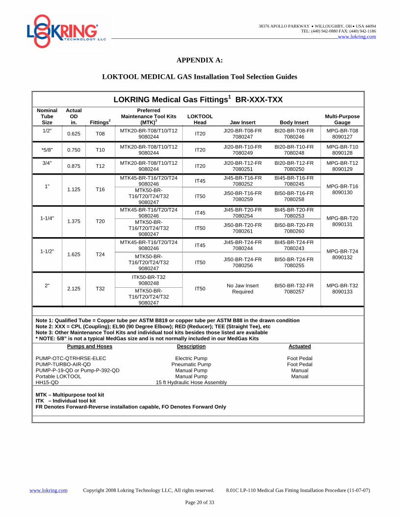
Using Appendix A as a guide, select the appropriate LOKTOOL head, body and jaw inserts, and MPG for the fitting size being installed.
½”, 5/8” and ¾” fittings use Tool Head IT20 1”, 1 ¼” and 1 ½” fittings use Tool Head IT45 or ITK50 1”, 1 ¼”, 1 ½” and 2” fittings use Tool Head IT50
Figure 12: Installation Tooling – copper colored MPG, body and jaw inserts have fittings size etched on them
38376 APOLLO PARKWAY • WILLOUGHBY, OH • USA 44094 TEL: (440) 942-0880 FAX: (440) 942-1186
www.lokring.com Copyright 2008 Lokring Technology LLC, All rights reserved. 8.01C LP-110 Medical Gas Fitting Installation Procedure (11-07-07)
Page 12 of 33
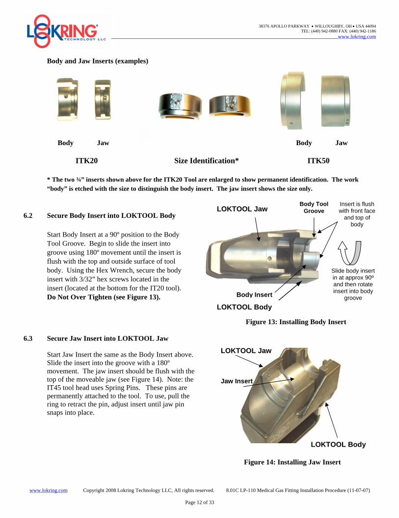
Body and Jaw Inserts (examples) Body Jaw Body Jaw ITK20 Size Identification* ITK50 * The two ¾” inserts shown above for the ITK20 Tool are enlarged to show permanent identification. The work
“body” is etched with the size to distinguish the body insert. The jaw insert shows the size only.
6.2 Secure Body Insert into LOKTOOL Body
Start Body Insert at a 90º position to the Body Tool Groove. Begin to slide the insert into groove using 180º movement until the insert is flush with the top and outside surface of tool body. Using the Hex Wrench, secure the body insert with 3/32” hex screws located in the insert (located at the bottom for the IT20 tool). Do Not Over Tighten (see Figure 13). Figure 13: Installing Body Insert
6.3 Secure Jaw Insert into LOKTOOL Jaw
Start Jaw Insert the same as the Body Insert above. Slide the insert into the groove with a 180º movement. The jaw insert should be flush with the top of the moveable jaw (see Figure 14). Note: the IT45 tool head uses Spring Pins. These pins are permanently attached to the tool. To use, pull the ring to retract the pin, adjust insert until jaw pin snaps into place.
Figure 14: Installing Jaw Insert
LOKTOOL Body
Insert is flush with front face
and top of body
LOKTOOL Jaw
Slide body insert in at approx 90º and then rotate insert into body
groove
Body Tool Groove
Body Insert
LOKTOOL Jaw
LOKTOOL Body
Jaw Insert
38376 APOLLO PARKWAY • WILLOUGHBY, OH • USA 44094 TEL: (440) 942-0880 FAX: (440) 942-1186
www.lokring.com Copyright 2008 Lokring Technology LLC, All rights reserved. 8.01C LP-110 Medical Gas Fitting Installation Procedure (11-07-07)
Page 13 of 33
For the IT20 note the position of the Hex Screw Hole in the jaw (and body) with the jaw (and body) insert. Reposition the inserts until the hex screw is engaged in the jaw (and body) hex screw hole of the jaw (or body). Using a hex wrench secure the insert into the jaw (and body) by tightening the hex screw until it bottoms out in the jaw (or body). Do Not Over Tighten.
The IT50 uses Spring Pins located on the side of the Jaw and Body. Pull the retractable pin, slide insert into position, release the pin to enter hole in jaw insert and then body insert. NOTE: The jaw for the IT50 requires two Pull Pins to secure the jaw insert. To release insert, tilt the tool head forward while pulling both pins. The 2” fitting does not require the use of a jaw insert (the jaw acts as the insert).
LOKTOOL Body
LOKTOOL Jaw
LOKTOOL Jaw
Hex Screw Hole in jaw and body
The jaw and body inserts’ Hex Screws aligned and tightened into jaw and body Hex Screw Holes.
Spring Pins
Rental Units: Some rental units have the IT45 Tool Head for install of 1”, 1 ¼” and 1 ½” inch fittings. The inserts are sized specific for the tool and cannot be interchanged with the IT50. Your rental instructions will advise if your kit has the IT45 Tool Head.
Extra Space for jaw insert is normal in IT50
38376 APOLLO PARKWAY • WILLOUGHBY, OH • USA 44094 TEL: (440) 942-0880 FAX: (440) 942-1186
www.lokring.com Copyright 2008 Lokring Technology LLC, All rights reserved. 8.01C LP-110 Medical Gas Fitting Installation Procedure (11-07-07)
Page 14 of 33
6.4 Connect Hose to Pump
NOTE: Flat Face Couplings and Nipples prevent halocarbon hydraulic fluid leakage (see Figure 15). Blue Nitrile gloves are provided and should be worn during the installation process. Connect the hose to the pump by pushing the coupling on to the nipple. Rotate the “notched” coupling sleeve ¼ turn to prevent accidental uncoupling of the connection. To release the coupling, the notch of the sleeve must be align- ed with the coupling pin. Pull the notch backward to re-
lease coupling from nipple (see Figure 16). Figure 15: Connecting Flat Face Coupling 6.5 Connect Hose to LOKTOOL Head
Connect the hose to the tool head by pushing the coupling on the nipple. Rotate the notched sleeve to lock coupling.
Figure 16: Connecting and Releasing Coupling and Nipple
Figure 17: Connecting the Hose to the Pump and Tool Head 6.6 Cycle Assembled Hydraulic System
Advance and retract the tool jaw several times without a fitting to ensure that no air is trapped in system and that the hydraulic couplers are fully secured (see Figure 18).
Note: If the LOKTOOL jaw does not advance and retract smoothly while cycling, air may be trapped in the system, and must be removed prior to operation or the tool may require maintenance. Follow the pump manufacturer’s instructions packaged with the pump to bleed air from the system.
Figure 18: Cycling System
Cycle tool back and forth
Flat Face Coupling
Flat Face Nipple
Pin
Notch
38376 APOLLO PARKWAY • WILLOUGHBY, OH • USA 44094 TEL: (440) 942-0880 FAX: (440) 942-1186
www.lokring.com Copyright 2008 Lokring Technology LLC, All rights reserved. 8.01C LP-110 Medical Gas Fitting Installation Procedure (11-07-07)
Page 15 of 33
6.7 Routine Maintenance
Perform routine maintenance on the tooling components in accordance with Appendix B. 6.8 Clean Tooling prior to Fitting Installation
In order to maintain the cleanliness of the tubing system, wipe down the tooling jaws, inserts and tool body prior to fitting installation.
7.0 LOKRING MEDICAL GAS FITTING INSTALLATION 7.1 Inspect Fitting
Inspect the fitting to ensure grit and contaminants are not present on the interior surfaces, or on the exterior of the body where the drive ring advances. NOTE: Contamination on the interior (or wetted surfaces) may result in system contamination. Note: LOKRING medical gas fittings are cleaned for oxygen service per CGA G-4.1 and bagged to prevent contamination. Do not remove fittings from their protective bag until you are ready to install them. If the product becomes contaminated, on-site cleaning per NFPA 99C-2005 before installation is required.
7.2 Slide Fitting over Prepared Tube End
Slide the LOKRING fitting over one tube end until the INSTALL mark (mark farthest from tube end) is partially covered by the fitting body.
The fitting should slide easily over the tube, and must not be forced. Forcing a fitting onto the tube end can damage the fitting sealing surfaces. Figure 19: Pre LOK Position
Note: For fittings with an internal center stop (e.g. caps and reducers), the tube can be fully "bottomed out" against this stop. When the tube is properly cut within 5° square and bottomed out, approximately half the INSTALL mark will be covered by the fitting drive ring.
7.3 Couplings with a Thru-Bore Design
LOKRING medical gas couplings are designed with a "thru-bore" design which allows them to slide completely over the tube and eliminates the need to "spring" the tube to get the fitting into position. These couplings do not have an internal center stop.
When installing these "thru-bore" designed couplings, ALWAYS make sure at least part of the INSTALL mark is covered by the fitting before making up the LOKRING connection (1/2 coverage of the INSTALL mark is best).
INSTALL Mark
38376 APOLLO PARKWAY • WILLOUGHBY, OH • USA 44094 TEL: (440) 942-0880 FAX: (440) 942-1186
www.lokring.com Copyright 2008 Lokring Technology LLC, All rights reserved. 8.01C LP-110 Medical Gas Fitting Installation Procedure (11-07-07)
Page 16 of 33
7.3.1 Using the MPG as a stop
To help in centering the tube in through bore couplings, the MPG's have a handle or "plug" on one end. When installing the first end of one of these couplings on the tube, insert the plug as far as possible into one end of the coup- ling until the shoulder contacts the driver. Then bottom out the tube against the plug, the plug will act as an artificial center stop for easier positioning of the tube.
When the tube is bottomed out against the plug, part of the INSTALL mark should be covered Figure 20: Using Gauge as a stop by the fitting and the other part should be exposed.
7.4 Verify position on Tube end
When properly inserted, at least some part of the INSTALL mark (mark furthest from tube end) should be visible.
Note: The length of the INSTALL mark is the tube insertion tolerance. Tube ends are properly inserted into the coupling provided that at least part of the INSTALL mark on both Figure 21: Verify Pre-assembled Position tube ends is visible.
7.5 Engage LOKTOOL on Fitting
With the LOKTOOL jaw fully retracted, engage the tool head on the fitting.
The body insert slot slides into the groove be- tween the fitting tool flanges, while the jaw insert cradles the fitting drive ring.
Some tools are forward/reverse capable which allows for installation closer to objects that may be in the way of normal installation. Figure 19 shows a forward installation where the body insert en- gages the center of the coupling. With a reverse installation, the tool is rotated 180º and the jaw insert engages the coupling body and the body in- sert cradles the drive ring see Appendix C. Figure 22: Tool Engaged on Fitting
Note: The LOKRING medical gas fitting must be fully engaged (bottomed out) on the LOKTOOL head before hydraulic actuation. If the fitting is "cocked" in the jaws, or not fully engaged, the fitting and/or tool may be damaged during fitting installation.
7.6 Verify Marks and Fit before Actuation
Verify that fitting is properly positioned on the INSTALL mark on the tube one last time before actuating hydraulic power.
INSTALL Mark partially covered by fitting and partially exposed
Gauge bottomed at fitting, tube contacting center section, “plug”, of gauge
INSTALL Mark
Fitting Tool Flanges
Jaw fully retracted
Body Insert Slot
38376 APOLLO PARKWAY • WILLOUGHBY, OH • USA 44094 TEL: (440) 942-0880 FAX: (440) 942-1186
www.lokring.com Copyright 2008 Lokring Technology LLC, All rights reserved. 8.01C LP-110 Medical Gas Fitting Installation Procedure (11-07-07)
Page 17 of 33
INSPECT Mark INSTALL Mark
7.7 Actuate Hydraulic Power
Note: Important technique: when using the manual pump, advance the jaw with slow pump action to the drive ring. Stop! Confirm the location of the in- stall mark. The next two to three hand pumps will secure the fitting to the tube. Continued actuation will cause the LOKTOOL jaw to advance the drive ring axially over the fitting body until it contacts the tool flange. When this happens, stop actuation of hydraulic power. Release hydraulic pressure on the pump. You have completed the installation of the LOKRING fitting.
THE FIRST END/TUBE CONNECTION IS NOW COMPLETE 7.8 Inspect First Installed End
Remove the LOKTOOL head from the installed coupling and inspect the first end installation. The INSTALL mark should now be largely or completely visible, and the INSPECT mark must be partially covered by the trailing edge of the fitting.
Figure 24: Inspection of Installed Fitting 7.9 Insert Second Tube End into Fitting
Verify that the second tube end is properly gauged and marked. Insert the second end into the open coupling end; it should slide easily into the fitting. Again, make sure at least some part of the INSTALL mark (mark furthest from tube end) is visible before installing Figure 25: Insert Second End into Fitting the fitting. (see section 7.4)
Note: If the tube must be forced into the fitting, it is possible that the tube ends are misaligned. Prior to hydraulic actuation, check that the tubes are properly aligned and supported to avoid pre-stressing the connection during installation (see paragraph 2.6, 2.7, & 2.8).
Figure 23: Drive Ring driven to Contact tool flange
38376 APOLLO PARKWAY • WILLOUGHBY, OH • USA 44094 TEL: (440) 942-0880 FAX: (440) 942-1186
www.lokring.com Copyright 2008 Lokring Technology LLC, All rights reserved. 8.01C LP-110 Medical Gas Fitting Installation Procedure (11-07-07)
Page 18 of 33
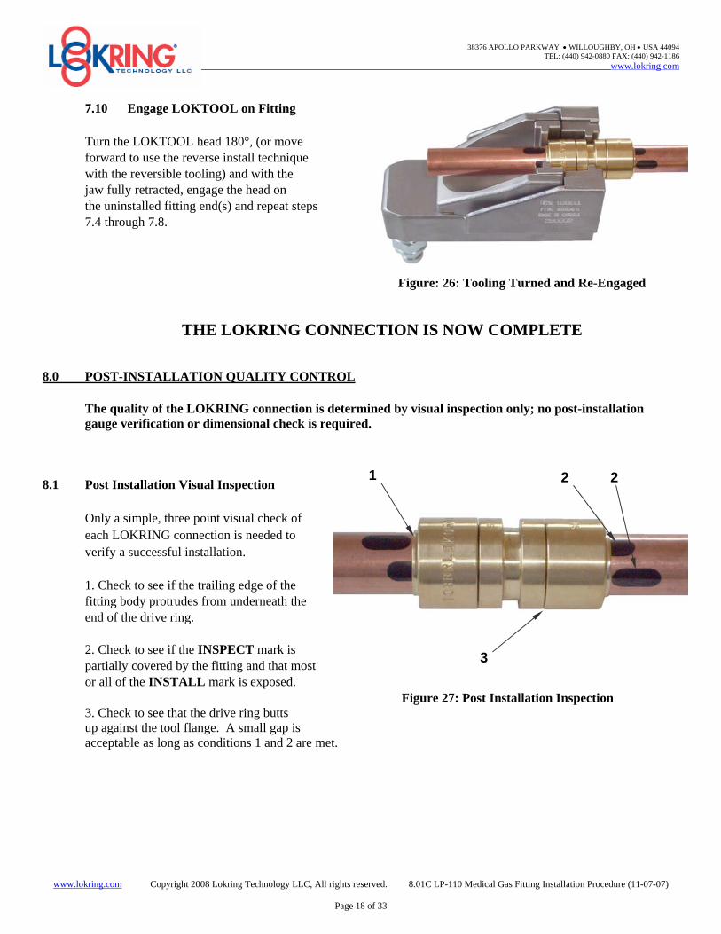
7.10 Engage LOKTOOL on Fitting
Turn the LOKTOOL head 180°, (or move forward to use the reverse install technique with the reversible tooling) and with the jaw fully retracted, engage the head on the uninstalled fitting end(s) and repeat steps 7.4 through 7.8.
Figure: 26: Tooling Turned and Re-Engaged
THE LOKRING CONNECTION IS NOW COMPLETE 8.0 POST-INSTALLATION QUALITY CONTROL
The quality of the LOKRING connection is determined by visual inspection only; no post-installation gauge verification or dimensional check is required.
8.1 Post Installation Visual Inspection
Only a simple, three point visual check of each LOKRING connection is needed to verify a successful installation. 1. Check to see if the trailing edge of the fitting body protrudes from underneath the end of the drive ring. 2. Check to see if the INSPECT mark is partially covered by the fitting and that most or all of the INSTALL mark is exposed.
Figure 27: Post Installation Inspection 3. Check to see that the drive ring butts up against the tool flange. A small gap is acceptable as long as conditions 1 and 2 are met.
2 2 1
3
38376 APOLLO PARKWAY • WILLOUGHBY, OH • USA 44094 TEL: (440) 942-0880 FAX: (440) 942-1186
www.lokring.com Copyright 2008 Lokring Technology LLC, All rights reserved. 8.01C LP-110 Medical Gas Fitting Installation Procedure (11-07-07)
Page 19 of 33
8.2 Good Installation
Each drive ring should be fully drawn up over the fitting body, and the trailing edge of the fitting should protrude from underneath the drive ring completely around it’s circumference. The INSTALL mark may be partially or completely uncovered; however, the INSPECT mark must be partially covered by the fitting trailing edge.
Note: A small gap between the drive ring and tool flange is acceptable provided Figure 28: Good Installation the fitting body extends from underneath the trailing edge of the drive ring at all points around the circumference of the fitting.
8.3 Incomplete Installation
One of the drive rings is not fully installed onto the fitting body. The trailing edge of one side of the fitting is not fully visible underneath the trailing edge of the drive ring.
The LOKTOOL head should be re-engaged onto the incomplete side and recycled to complete the installation. Figure 29: Incomplete Installation
8.4 Bad Installation
The INSPECT mark on each tube end must be partially covered by the fitting body. If the INSPECT mark is fully visible, the tube on that fitting leg was insufficiently inserted into the fitting and the fitting must be removed.
When using couplings with the thru-bore design, it is possible that 100% of the INSPECT mark on one end of the connection could be covered by the fitting body. Figure 30: Bad Installation
This is a bad installation because it indicates that the first tube has been inserted too far into the fitting. As a result, it will not be possible for the second tube to be inserted far enough into the fitting to meet the installation requirements. Therefore, the fitting must be removed.
8.5 The LOKRING connection is now ready for leak testing. No Purging is necessary!
Fitting body does not extend From underneath the ESP ring
Inspect mark not partially covered
Fitting body extends from Underneath the Drive Ring
Inspect mark partially covered
Inspect mark not visible
38376 APOLLO PARKWAY • WILLOUGHBY, OH • USA 44094 TEL: (440) 942-0880 FAX: (440) 942-1186
Note 1: Qualified Tube = Copper tube per ASTM B819 or copper tube per ASTM B88 in the drawn condition Note 2: XXX = CPL (Coupling); EL90 (90 Degree Elbow); RED (Reducer); TEE (Straight Tee), etc Note 3: Other Maintenance Tool Kits and individual tool kits besides those listed are available * NOTE: 5/8” is not a typical MedGas size and is not normally included in our MedGas Kits
www.lokring.com Copyright 2008 Lokring Technology LLC, All rights reserved. 8.01C LP-110 Medical Gas Fitting Installation Procedure (11-07-07)
Page 21 of 33
APPENDIX B:
Safety & Maintenance Instructions for LOKTOOL Installation Tools
LOKTOOL System General Safety Instructions 1. LOKTOOL system components (head, couplers, hoses, pumps) are fully rated for 10,000 psi operating pressure.
Do not substitute non-approved components without prior authorization of LOKRING. 2. Make sure Quick Disconnects are fully secured, and that threaded locking ring on the hose coupler is fully
advanced to ensure against accidental separation of installation tool from hose during operation or transportation.
Note: Loose couplers will act as a partial or complete line restriction causing little or no oil flow and resulting in equipment damage or failure.
3. Cycle tool several times without fitting to assure that quick disconnects are fully secured, and no air is trapped in
the system.
Note: If the LOKTOOL jaw does not advance and retract smoothly, air might be trapped in system and must be bled prior to operation. Follow manufacturer's instructions included with hydraulic pump.
4. Be sure that LOKRING fittings are fully seated in the LOKTOOL jaws before actuating hydraulic pressure.
Fittings that are "cocked" or not fully seated can damage fitting and/or tool. 5. Keep fingers clear of the jaws during the activation cycle. 6. NEVER ATTEMPT TO DISASSEMBLE LOKTOOL HEADS. Call your local LOKRING Distributor or the
Factory immediately if any problems with the tools are encountered. 7. Do not drop heavy objects on hoses, and make sure that the hoses are never kinked or sharply bent. Always
provide adequate clearance for hoses and coupler to avoid moving objects, abrasion, or sharp objects. 8. Keep hydraulic equipment and hoses away from flames and heat. For optimum performance, do not expose
equipment to temperatures of 150°F or higher. 9. Do not use LOKTOOL components that show signs of damage, abuse, or excessive wear. 10. Clean LOKTOOL head and lubricate bearing surfaces with KRYTOX GPL205 on a daily basis after use.
Although the LOKTOOL does not contact wetted surfaces, it is best to ensure that contamination cannot be sourced to the tool. Clean accordingly.
11. Do not attempt to install LOKRING fittings with broken or damaged inserts nor with inserts of the wrong size. 12. If there is any sign of hydraulic fluid leakage, consult your local LOKRING Distributor or the Factory for
assistance.
38376 APOLLO PARKWAY • WILLOUGHBY, OH • USA 44094 TEL: (440) 942-0880 FAX: (440) 942-1186
www.lokring.com Copyright 2008 Lokring Technology LLC, All rights reserved. 8.01C LP-110 Medical Gas Fitting Installation Procedure (11-07-07)
Page 22 of 33
APPENDIX B:
Safety & Maintenance Instructions for LOKTOOL Installation Tools
LOKTOOL Head Maintenance & Cleaning Instructions: The LOKTOOL body and jaw (and body and jaw inserts) are manufactured from high strength materials, precision machined for many years of reliable service. Assembled tools require no calibration. However, regular cleaning and lubrication of the bearing surfaces is required for proper maintenance of the tools. The following general cleaning procedures are recommended on a daily basis following use: 1. Clean installation tooling jaws of all foreign material. Brush or blow debris out of jaw cavity from top (looking
down between the tool jaws). 2. Rag wipe front bearing pad or bushing, and apply KRYTOX GPL205, as needed to the pad after cleaning.
Note: LOKTOOL head sizes IT45 and IT50 have a flat bronze wear pad between the LOKTOOL jaw and body, visible when looking down into the tool cavity from above.
3. Advance the LOKTOOL jaw (without fitting) until it is in the closed position. Clean and KRYTOX GPL205 the
sliding (bearing) surfaces on the tool body and behind the advanced jaw (if applicable to specific tool model). 4. Make sure that body and jaw inserts are properly oriented in LOKTOOL head and secured with set screws. 5. Return LOKTOOL head to equipment case for storage after use.
once hose, pump, and LOKTOOL head are connected. For manual pump, fill to indicator mark with Halocarbon on the end cap. Replace the fill cap and be sure it is closed.
Note: Always use pump manufacturer’s recommended fluid only. Introduction of other brand hydraulic fluids into the system may contaminate the system, and may void pump warranty.
2. Always cover disconnect coupler halves with dust caps. As with any hydraulic system, use every precaution to
guard LOKTOOL head, hose, and pump against entrance of dirt.
38376 APOLLO PARKWAY • WILLOUGHBY, OH • USA 44094 TEL: (440) 942-0880 FAX: (440) 942-1186
www.lokring.com Copyright 2008 Lokring Technology LLC, All rights reserved. 8.01C LP-110 Medical Gas Fitting Installation Procedure (11-07-07)
Page 23 of 33
APPENDIX C:
LOKRING Tool Placement Options
LOKRING™ Reverse Tool Installation Technique
Normal Tool Use Reverse Tool Use (where space constrained by bulkhead
or adjacent fitting)
Fully engage tool on fitting with the tool groove on fitting going into the body insert of the tool
Actuate tool, holding the body of the tool stationary while the tool jaw advances the drive ring onto the fitting body
Turn tool 180º and re-engage on the opposite side of the fitting. Repeat tool operation as described above
Note: 1. Using the tool in reverse requires special attention to make sure the fitting does not move during tool actuation. For this reason it is recommended that where possible the first joint is pulled up in normal fashion to lock the fitting in place 2. Not all LOKRING tools will work in reverse. If the fitting will go into tool in reverse position, then this tool is reverse capable. Contact your LOKRING representative for details on this capability
For the first side of the fitting engage and actuate tool as described to the left
For the second space constrained joint, advance and re-engage tool with fitting groove in the jaw insert
Actuate tool, allowing the tool body to travel and advance the drive ring while the tool jaw remains stationary
38376 APOLLO PARKWAY • WILLOUGHBY, OH • USA 44094 TEL: (440) 942-0880 FAX: (440) 942-1186
Spool lengths are for reverse operation, except where noted. Spool lengths may be decreased slightly if one fitting end can be pulled up prior to positioning the second end and the reverse position of the tool is used for the installation.
S X A A
H
L
38376 APOLLO PARKWAY • WILLOUGHBY, OH • USA 44094 TEL: (440) 942-0880 FAX: (440) 942-1186
www.lokring.com Copyright 2008 Lokring Technology LLC, All rights reserved. 8.01C LP-110 Medical Gas Fitting Installation Procedure (11-07-07)
Page 26 of 33
APPENDIX E:
LOKRING Fitting Installation Training Certification Test
Installer Information Name ________________________________ Date ____________________________ Employee Number ________________________ Company __________________________
Plant ______________________________
Questions 1. If you are planning to install LOKRING fittings, and would like to review the installation procedures,
what is available to help you do this? 1) ____________________________________________________________________________________________ 2) ____________________________________________________________________________________________ 3) ____________________________________________________________________________________________ 4) ____________________________________________________________________________________________ 5) ____________________________________________________________________________________________ 6) ____________________________________________________________________________________________
2. Define the LOKRING Sealing Zone. _________________________________________________________________ LOKRING fitting should be installed ______distance from a brazed joint. 3. What should you do if you have a deep scratch in the Sealing Zone? __________________________________________________________________________________________________ 4. How do you check for proper squareness of the cut tube end? _____________________________________________ __________________________________________________________________________________________________ 5. How do you check for tube that is undersized (outside of specification) or excessively oval? __________________________________________________________________________________________________ 6. When using the multi-purpose gauge, the name of the two marks you put on the tube are: 1) ________________________________________ 2) ________________________________________________ 7. When the tube is properly inserted into the uninstalled (un-LOK-ed) fitting, what portion of the two marks should you be able to see? ______________________________________________________________________________ When the fitting has been completed what portion of the two marks should then be revealed? _______________________________________________________________________________________________ 8. How can you check for proper alignment of two tube ends before making up the fitting? ________________________ __________________________________________________________________________________________________
38376 APOLLO PARKWAY • WILLOUGHBY, OH • USA 44094 TEL: (440) 942-0880 FAX: (440) 942-1186
www.lokring.com Copyright 2008 Lokring Technology LLC, All rights reserved. 8.01C LP-110 Medical Gas Fitting Installation Procedure (11-07-07)
Page 27 of 33
APPENDIX E:
LOKRING Fitting Installation Training Certification Test
9. After connecting the hose coupler to the LOKTOOL head, what two things should be done before installing any
fitting? 1) _____________________________ 2) ______________________________________________________ 10. Before actuating hydraulic power to LOK a fitting, what two things should you check for? 1) ________________________________________ 2) _________________________________________________ 11. What is likely to happen if the LOKTOOL head is not fully engaged on the fitting? 1) __________________________________ and/or 2) _________________________________________________ 12. After making-up the fitting, what are three visual checks for proper installation?
www.lokring.com Copyright 2008 Lokring Technology LLC, All rights reserved. 8.01C LP-110 Medical Gas Fitting Installation Procedure (11-07-07)
Page 28 of 33
APPENDIX E:
LOKRING Fitting Installation Training Certification Test Answers
1. If you are planning to install LOKRING fittings, and would like to review the installation procedures, what is available to help you do this?
1) LP-110 Medical Gas Fitting Installation Procedure 2) LOKRING Installation Procedures Video 3) LOKRING Pipefitter’s Field Installation Guide 4) LOKRING Kit Mounted 5 Step Installation Guide 5) Hands-on LOKRING training session by LOKRING or authorized personnel 6) LOKRING internet site www.lokring.com
2. Define the LOKRING Sealing Zone The Sealing Zone is defined as the area on the surface of the tube extending 1 and 1/2 tube diameters from the end of the tube. LOKRING fitting should be installed 6 inches distance from a brazed joint. 3. What should you do if you have a deep scratch in the Sealing Zone? Cut the tube back to an area clear of surface condition problems, and repeat Sealing Zone preparation steps. 4. How do you check for proper squareness of the cut tube end? End cut cannot be greater than +/- 5° from square. Verification of end cut tolerance can be obtained using the LOKRING Multi-Purpose Gauge. 5. How do you check for tube that is undersized (outside of specification), or excessively oval?
1) Using the Multipurpose Gauging Tool (MPG), and the NO-GO section of the gauge, place it lightly against the tube at two points 90° apart from each other. If the tube end does not pass through the NO-GO section of the gauge then it is not undersized, or excessively oval.
2) You may also measure the tube O.D. with a caliper or other suitable device and compare with the minimum
specification values for that specific tube diameter. 6. When using the multi-purpose gauge, the names of the two marks you put on the tube are?
1) Install Mark 2) Inspect mark
7. When the tube is properly inserted into the uninstalled (un-LOK-ed) fitting, what portion of the two marks should you be able to see?
1/2 of the install When the fitting has been completed, what portion of the two marks should then be revealed? 1 1/2 or 1 and a portion
38376 APOLLO PARKWAY • WILLOUGHBY, OH • USA 44094 TEL: (440) 942-0880 FAX: (440) 942-1186
www.lokring.com Copyright 2008 Lokring Technology LLC, All rights reserved. 8.01C LP-110 Medical Gas Fitting Installation Procedure (11-07-07)
Page 29 of 33
APPENDIX E: LOKRING Fitting Installation Training Certification Test Answers
8. How can you check for proper alignment of two tube ends before making up the fitting? Verify tube orientation inside the fitting by inspecting install and inspect marks. 9. After connecting the hose coupler to the LOKRING tool head, what two things should be done before installing any fittings?
1) Advance the hose coupler thread locking ring manually against the coupler locking sleeve. Secure thread locking ring
2) Advance and retract tool jaw several times without fitting to ensure that no air is trapped in system, and that all hydraulic couplers are fully secured
10. Before actuating hydraulic power to LOK a fitting, what two things should you check for?
1) Fitting is secure in tool head 2) A portion of the installation mark is showing
11. What is likely to happen if the LOKTOOL head is not fully engaged on the fitting? The fitting and/or tool may be damaged during LOK-ing 12. After making-up a fitting, what are the three visual checks for proper installation?
1) Check to see if the trailing edge of the fitting body protrudes from underneath the end of the drive ring. 2) Check to see if a portion of the INSPECT mark is covered by the fitting and that most or all of the INSTALL
mark is exposed. 3) Check to see that the drive ring is fully seated against the inner land of the fitting body (a small gap on one side is acceptable if "1" and “2” are met)
13. What are the three areas in which installation errors occur when installing LOKRING fittings?
1*) One of the drive rings is not fully seated against the fitting body, resulting in the trailing edge of the fitting body not protruding.
2**) The fitting’s INSPECT mark on either end of the tube is completely exposed 3***) The repair fitting’s INSPECT mark is not visible at all on one end of the tube.
*Solution: Position and engage the LOKTOOL again until the drive ring has become fully seated and continue post LOK inspection procedure **Solution: Tube was not sufficiently inserted into fitting and must be cut out and replaced ***Solution: Tube was over inserted into the repair fitting and must be cut out and replaced. 14. True or False: If the product becomes contaminated, on-site cleaning per NFPA 99C-2005 before installation is acceptable?
True
38376 APOLLO PARKWAY • WILLOUGHBY, OH • USA 44094 TEL: (440) 942-0880 FAX: (440) 942-1186
www.lokring.com Copyright 2008 Lokring Technology LLC, All rights reserved. 8.01C LP-110 Medical Gas Fitting Installation Procedure (11-07-07)
Page 30 of 33
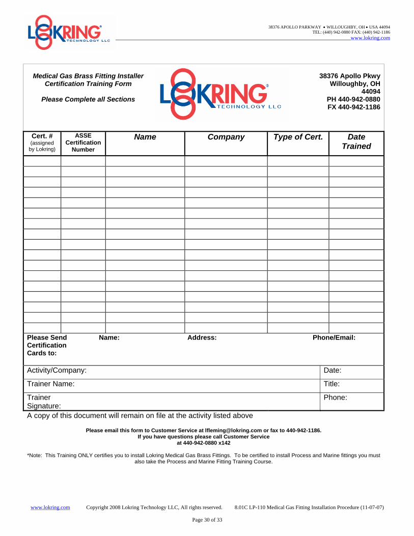
Medical Gas Brass Fitting Installer Certification Training Form
Please Complete all Sections
38376 Apollo Pkwy
Willoughby, OH44094
PH 440-942-0880 FX 440-942-1186
Cert. # (assigned
by Lokring)
ASSE Certification
Number
Name Company Type of Cert. Date Trained
Please Send Name: Address: Phone/Email: Certification Cards to: Activity/Company: Date:
Trainer Name: Title:
Trainer Signature:
Phone:
A copy of this document will remain on file at the activity listed above
Please email this form to Customer Service at [email protected] or fax to 440-942-1186. If you have questions please call Customer Service
at 440-942-0880 x142
*Note: This Training ONLY certifies you to install Lokring Medical Gas Brass Fittings. To be certified to install Process and Marine fittings you must also take the Process and Marine Fitting Training Course.
38376 APOLLO PARKWAY • WILLOUGHBY, OH • USA 44094 TEL: (440) 942-0880 FAX: (440) 942-1186
Name: Company: Date Trained: Certification Number:
Authorized Signature:______________
Five Simple Steps to a LOKRINGTM End Connection 1. Cut and prepare tube ends. 2. Check tube ends for square cut, check tube.
O.D. and mark tube ends with gauge (MPG). 3. Inspect, assemble and cycle installation tooling. 4. Position fitting on Install mark, fully engage
tool onto fitting and cycle tool. 5. Post installation inspection (3 point visual check).
www.lokring.com Copyright 2008 Lokring Technology LLC, All Rights Reserved 8.03 5 Step Tri-Fold Handout for BR Medical Gas Fittings
LOKRING INSTALLER’S
Field Installation Guide
For Series BR Brass LOKRINGTM Tube
Fittings. For use with Copper Tube in
Medical Gas and Vacuum Applications
38376 Apollo Parkway Willoughby, Ohio 44094
Toll Free: (800) 876-2323 Phone: (440) 942-0880
Fax: (440) 942-1186
INSTALLATION PROCEDURE Note: Refer to LOKRING procedure LP-110 for detailed installation instructions STEP 1: Sealing zone shall be a minimum of 6” from brazed joint. If necessary, before cutting tube, use a non-shedding abrasive pad to clean surface and remove scratches from tube OD. Care should be taken to not contaminate the inside of the tube. Always clean tube sealing zone in circumferential direction Cut tube with clean tubing cutter to within 5º square.
Step 2: Using the Multi-Purpose Gauge, verify that the tube OD is correctly sized, and mark the tube ends as shown.
Fitting body protrudes from underneath swage ring
INSPECT mark partially covered
Small gap is acceptable
INSTALL Mark
D
5º
Seal ing Zone 1-1/2 D
5º
Fitting fully bottomed-out In tool jaws
®
STEP 3: Select and assemble required LOKRING tool. Inspect and cycle tool to assure proper function. STEP 4: Position fitting on “INSTALL” mark, fully engage and actuate tool.
www.lokring.com Copyright 2008 Lokring Technology LLC, All Rights Reserved 8.03 5 Step Tri-Fold Handout for BR Medical Gas Fittings
Fitting Take-Out “T” in 1/16” Increments Reducers RED (T)
1. For use on positive pressure medical gas tube per B819 and for vacuum copper tube per ASTM B88. 2. Minimum cut spool length “S” listed is for reverse installation. Spool lengths may be decreased slightly if one fitting end can be pulled up prior to positioning the second end and the reverse position of the tool is used for the installation. * Consult LOKRING for Take-Out dimension


![[ Die LOKRING Rohrverbindung ] - Autoklimaanlage · Die LOKRING-Rohrverbindung ist durch Patente und Patentan- meldungen weltweit geschützt. Wichtig Die LOKRING-Gesellschaften liefern](https://static.documents.pub/doc/80x56/5ec6e930d3f1fa60cb7e77f8/-die-lokring-rohrverbindung-die-lokring-rohrverbindung-ist-durch-patente-und.jpg)


