+ All Categories
Home > Documents > LP gas & High Altitude Conversion Guide

LP gas & High Altitude Conversion Guide

Date post: 07-Dec-2021
Category:
Upload: others
View: 2 times
Download: 0 times
Share this document with a friend
2
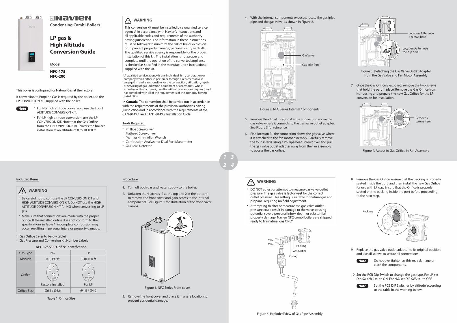
1 2 3 4 Condensing Combi-Boilers LP gas & High Altitude Conversion Guide Model NFC-175 NFC-200 This boiler is configured for Natural Gas at the factory. If conversion to Propane Gas is required by the boiler, use the LP CONVERSION KIT supplied with the boiler. Note For NG high altitude conversion, use the HIGH ALTITUDE CONVERSION KIT. For LP high altitude conversion, use the LP CONVERSION KIT. Note that the Gas Orifice from the LP CONVERSION KIT covers the boiler's installation at an altitude of 0 to 10,100 ft. Included Items: WARNING Be careful not to confuse the LP CONVERSION KIT and HIGH ALTITUDE CONVERSION KIT. Do NOT use the HIGH ALTITUDE CONVERSION KIT for NG when converting to LP gas. Make sure that connections are made with the proper orifice. If the installed orifice does not conform to the specifications in Table 1, incomplete combustion may occur, resulting in personal injury or property damage. Gas Orifice (refer to below table) Gas Pressure and Conversion Kit Number Labels NFC-175/200 Orifice Identification Gas Type NG LP Altitude 0-5,399 ft 0-10,100 ft Orifice NFC-200 NG NFC-200 LP Factory Installed For LP Orifice Size Ø6.1 / Ø6.6 Ø4.5 / Ø4.9 Table 1. Orifice Size 4. With the internal components exposed, locate the gas inlet pipe and the gas valve, as shown in Figure 2. Gas Valve Gas Inlet Pipe Figure 2. NFC Series Internal Components 5. Remove the clip at location A – the connection above the gas valve where it connects to the gas valve outlet adapter. See Figure 3 for reference. 6. Find location B - the connection above the gas valve where it is attached to the fan motor assembly. Carefully remove the four screws using a Phillips-head screwdriver and pull the gas valve outlet adapter away from the fan assembly to access the gas orifice. WARNING DO NOT adjust or attempt to measure gas valve outlet pressure. The gas valve is factory-set for the correct outlet pressure. This setting is suitable for natural gas and propane, requiring no field adjustment. Attempting to alter or measure the gas valve outlet pressure could result in damage to the valve, causing potential severe personal injury, death or substantial property damage. Navien NFC combi boilers are shipped ready to fire natural gas ONLY. O-ring Packing Gas Orifice Figure 5. Exploded View of Gas Pipe Assembly WARNING This conversion kit must be installed by a qualified service agency* in accordance with Navien’s instructions and all applicable codes and requirements of the authority having jurisdiction. The information in these instructions must be followed to minimize the risk of fire or explosion or to prevent property damage, personal injury or death. The qualified service agency is responsible for the proper installation of this kit. The installation is not proper and complete until the operation of the converted appliance is checked as specified in the manufacturer’s instructions supplied with the kit. * A qualified service agency is any individual, firm, corporation or company which either in person or through a representative is engaged in and is responsible for the connection, utilization, repair or servicing of gas utilization equipment or accessories; who is experienced in such work, familiar with all precautions required, and has complied with all of the requirements of the authority having jurisdiction. In Canada: The conversion shall be carried out in accordance with the requirements of the provincial authorities having jurisdiction and in accordance with the requirements of the CAN‐B149.1 and CAN1‐B149.2 Installation Code. Tools Required: Phillips Screwdriver Flathead Screwdriver 5 /32 in or 4 mm Allen Wrench Combustion Analyzer or Dual Port Manometer Gas Leak Detector Procedure: 1. Turn off both gas and water supply to the boiler. 2. Unfasten the 4 latches (2 at the top and 2 at the bottom) to remove the front cover and gain access to the internal components. See Figure 1 for illustration of the front cover clamps. Figure 1. NFC Series Front cover 3. Remove the front cover and place it in a safe location to prevent accidental damage. Location B: Remove 4 screws here Location A: Remove the clip here Figure 3. Detaching the Gas Valve Outlet Adapter from the Gas Valve and Fan Motor Assembly 7. Once the Gas Orifice is exposed, remove the two screws that hold the part in place. Remove the Gas Orifice from its housing and prepare the new Gas Orifice for the LP conversion for installation. Remove 2 screws here Figure 4. Access to Gas Orifice in Fan Assembly 8. Remove the Gas Orifice, ensure that the packing is properly seated inside the port, and then install the new Gas Orifice for use with LP gas. Ensure that the Orifice is properly seated on the packing inside the port before proceeding to the next step. Packing 9. Replace the gas valve outlet adapter to its original position and use all screws to secure all connections. Note Do not overtighten as this may damage or crack the components. 10. Set the PCB Dip Switch to change the gas type. For LP, set Dip Switch 2 #1 to ON. For NG, set DIP SW2 #1 to OFF. Note Set the PCB DIP Switches by altitude according to the table in the warning below.
Transcript

12

34

Condensing Combi-Boilers

LP gas & High Altitude Conversion Guide

Model

NFC-175 NFC-200

This boiler is configured for Natural Gas at the factory.

If conversion to Propane Gas is required by the boiler, use the LP CONVERSION KIT supplied with the boiler.

Note ● For NG high altitude conversion, use the HIGH ALTITUDE CONVERSION KIT.

● For LP high altitude conversion, use the LP CONVERSION KIT. Note that the Gas Orifice from the LP CONVERSION KIT covers the boiler's installation at an altitude of 0 to 10,100 ft.

Included Items:

WARNING

● Be careful not to confuse the LP CONVERSION KIT and HIGH ALTITUDE CONVERSION KIT. Do NOT use the HIGH ALTITUDE CONVERSION KIT for NG when converting to LP gas.

● Make sure that connections are made with the proper orifice. If the installed orifice does not conform to the specifications in Table 1, incomplete combustion may occur, resulting in personal injury or property damage.

● Gas Orifice (refer to below table) ● Gas Pressure and Conversion Kit Number Labels

NFC-175/200 Orifice Identification

Gas Type NG LP

Altitude 0-5,399 ft 0-10,100 ft

OrificeNFC-200

NGNFC-200

LP

Factory Installed For LP

Orifice Size Ø6.1 / Ø6.6 Ø4.5 / Ø4.9

Table 1. Orifice Size

4. With the internal components exposed, locate the gas inlet pipe and the gas valve, as shown in Figure 2.

Gas Valve

Gas Inlet Pipe

Figure 2. NFC Series Internal Components

5. Remove the clip at location A – the connection above the gas valve where it connects to the gas valve outlet adapter. See Figure 3 for reference.

6. Find location B - the connection above the gas valve where it is attached to the fan motor assembly. Carefully remove the four screws using a Phillips-head screwdriver and pull the gas valve outlet adapter away from the fan assembly to access the gas orifice.

WARNING

● DO NOT adjust or attempt to measure gas valve outlet pressure. The gas valve is factory-set for the correct outlet pressure. This setting is suitable for natural gas and propane, requiring no field adjustment.

● Attempting to alter or measure the gas valve outlet pressure could result in damage to the valve, causing potential severe personal injury, death or substantial property damage. Navien NFC combi boilers are shipped ready to fire natural gas ONLY.

O-ring

Packing

Gas Orifice

Figure 5. Exploded View of Gas Pipe Assembly

WARNING

This conversion kit must be installed by a qualified service agency* in accordance with Navien’s instructions and all applicable codes and requirements of the authority having jurisdiction. The information in these instructions must be followed to minimize the risk of fire or explosion or to prevent property damage, personal injury or death. The qualified service agency is responsible for the proper installation of this kit. The installation is not proper and complete until the operation of the converted appliance is checked as specified in the manufacturer’s instructions supplied with the kit.

* A qualified service agency is any individual, firm, corporation or company which either in person or through a representative is engaged in and is responsible for the connection, utilization, repair or servicing of gas utilization equipment or accessories; who is experienced in such work, familiar with all precautions required, and has complied with all of the requirements of the authority having jurisdiction.

In Canada: The conversion shall be carried out in accordance with the requirements of the provincial authorities having jurisdiction and in accordance with the requirements of the CAN‐B149.1 and CAN1‐B149.2 Installation Code.

Tools Required: ● Phillips Screwdriver ● Flathead Screwdriver ● 5/32 in or 4 mm Allen Wrench ● Combustion Analyzer or Dual Port Manometer ● Gas Leak Detector

Procedure:

1. Turn off both gas and water supply to the boiler.

2. Unfasten the 4 latches (2 at the top and 2 at the bottom) to remove the front cover and gain access to the internal components. See Figure 1 for illustration of the front cover clamps.

Figure 1. NFC Series Front cover

3. Remove the front cover and place it in a safe location to prevent accidental damage.

Location B: Remove 4 screws here

Location A: Remove the clip here

Figure 3. Detaching the Gas Valve Outlet Adapter from the Gas Valve and Fan Motor Assembly

7. Once the Gas Orifice is exposed, remove the two screws that hold the part in place. Remove the Gas Orifice from its housing and prepare the new Gas Orifice for the LP conversion for installation.

Remove 2 screws here

Figure 4. Access to Gas Orifice in Fan Assembly

8. Remove the Gas Orifice, ensure that the packing is properly seated inside the port, and then install the new Gas Orifice for use with LP gas. Ensure that the Orifice is properly seated on the packing inside the port before proceeding to the next step.

Packing

9. Replace the gas valve outlet adapter to its original position and use all screws to secure all connections.

Note Do not overtighten as this may damage or crack the components.

10. Set the PCB Dip Switch to change the gas type. For LP, set Dip Switch 2 #1 to ON. For NG, set DIP SW2 #1 to OFF.

Note Set the PCB DIP Switches by altitude according to the table in the warning below.

56

78

WARNING

Ensure that you have turned off the power to the boiler before accessing the DIP switches.

1 2 3 4 5 6

ON

ON

1 2 3 4 5 6 7 8

Switch Function Setting

1 Gas TypeNatural Gas 1-OFF

Propane Gas 1-ON

2&3 High Altitude

0-1,999 ft (0-609m) 2-OFF, 3-OFF

2,000-5,399 ft (610-1,645m) 2-ON, 3-OFF

5,400-7,699 ft (1,646-2,346m) 2-OFF, 3-ON

7,700-10,100 ft (2,347-3,078m) 2-ON, 3-ON

Note Depending on the gas type and high altitude settings, the orifice size used for the boiler varies. See Table 1 on the page 2 for details on orifice sizes.

b. Insert the analyzer into the port (Figure 6).

Figure 6. Insert the Analyzer

Model FuelHigh fire Low fire

%CO2 %CO2

NFC-175/200

NG 8.9 9.5

LP 10.2 10.8

Table 2. CO2 value(CO2 values must be within 0.5% of the values listed.)

d. Activate multiple zones and set the boiler to operate at 2-stage D. MAX mode. Measure the CO2 value at high fire.

If the CO2 values do not match Table 2 at high fire, do not adjust the gas valve. Check for the proper Gas Orifice.

DANGER

Improper gas valve settings can cause severe personal injury, death or substantial property damage.

Option 2. Using Digital Manometera. Open the offset pressure port by loosening the screw

two turns as shown in Figure 8.

Digital pressure manometer

Figure 8. Connect Digital Pressure Monometer

Figure 9. Set Screw Location

Note The set screw is located behind the screw-on cover. This must be removed first.

Note ● This unit may be installed at elevations up to 10,100 ft (3,078 m) for use with natural gas and propane. To use the unit at a specific altitude, the DIP Switches should be set as described above.

● High Altitude: Above 2,000 ft (610 m), the unit will de-rate by 3% for each 1,000 ft (305 m) of altitude gain.

DANGER

● When conversion is required, be sure to set the PCB DIP switch 2 #1 according to the supply gas type.

● Note that the Gas Orifice from the LP CONVERSION KIT covers the boiler's installation at an altitude of 0 to 10,100 ft.

● Failure to properly set the DIP switches could cause carbon monoxide poisoning, resulting in severe personal injury or death.

11. Turn on the gas and water supply to the boiler.

12. Measure and adjust the gas/air ratio.Option 1. Using Combustion Analyzer (recommended)a. Loosen the screw, rotate the plate and remove the

gasket to access the emissions monitoring port as shown in Figure 6.

c. Activate multiple zones and set the boiler to operate at 1-stage MIN mode.

Measure the CO2 value at low fire. If the CO2 value is not within 0.5% of the value listed in Table 2, the gas valve set screw will need to be adjusted. If adjustment is necessary, locate the set screw as shown in Figure 7. Using a 5/32 in or 4 mm Allen wrench, turn the set screw no more than 1/4 turn clockwise to raise or counterclockwise to lower the CO2 value.

Figure 7. Set Screw Location

Note The set screw is located behind the screw-on cover. This must be removed first.

b. Connect a manometer to the offset pressure port. For dual port manometers, use the positive pressure side.

Model Kit Part No. Gas Type Offset

NFC-175/200

NAC-N200 NG -0.04 in ±0.01 in

NAC-LC200 LP -0.02 in ±0.01 in

Table 3. Offset value for low fire

c. Activate multiple zones and set the boiler to operate at 1-stage MIN mode. Measure the offset value at low fire and compare it to the values in Table 3. If the offset value is out of range, the gas valve set screw will need to be adjusted.

If adjustment is necessary, locate the set screw as shown in Figure 9. Using a 5/32 in or 4mm Allen wrench, turn the set screw no more than 1/4 turn clockwise to raise or counterclockwise to lower the offset value.

d. At high fire, do not check the offset value and never adjust the gas valve.

DANGER

Improper gas valve settings can cause severe personal injury, death or substantial property damage.

13. Once the CO2 or offset values have been confirmed, apply the included conversion stickers to show that the appliance has been converted to propane gas. Place these labels adjacent to the rating plate as shown in Figure 10.

Ori�ce Size / Injecteur:Min. 4.5 mm to Max. 4.9 mm

This unit has beenconverted to Propane fuel

Cet appareil a ete converti au Propane

Manifold Gas Pressure /Pression à la tubulure d’alimentation:

-0.45 in WC

BTU Input / Debit calori�que:Max. 199,900 - Min. 18,000 BTUh

Conversion Kit No.: NAC-LC200

Inlet Gas Pressure / Pression d'entrée du gaz:Min. 8.0 to Max. 13.0 in WC

Figure 10. Proper Placement of Gas Conversion Labels

Note The gas conversion rating plate varies depending on the model. Check the conversion kit number before attaching the labels.Navien, Inc.

20 Goodyear lrvine, CA 92618TEL 1-800-519-8794 FAX 1-949-420-0430www.navien.com


Recommended