18
A Practical Guide to Low-Power Design User Experience with CPF When Do You Know You Have Saved Enough Power?
| Date post: | 02-Dec-2015 |
| Category: |
Documents |
| Upload: | gustavo-rossi |
| View: | 213 times |
| Download: | 1 times |

A Practical Guide to Low-Power DesignUser Experience with CPF
When Do You Know You Have Saved Enough Power?

When Do You Know You Have Saved Enough Power?
Sec12:2
When Do You Know You Have Saved Enough Power?By David Weir, Lead Design Engineer, Cadence Design.
Impact of Low-Power DesignAs everyone in wireless, consumer, multi-media, server, router, automotive and medical applications recognize, power consumption can be the key product differentiation and the key metric for success in the market. Three critical factors emerge:
• Peakpower• Averagepower• Timerequiredtoswitchbetweenpowermodes
Peakpowerimpactscostadvantage,inthesensethat,fordeviceshavingmultiplemodes of operation, the highest power mode determines area, packaging and possibly heat sink cost of goods.Averagepower,againuniquelyforthekeymodesofoperationofthechip,determinesbattery life.The time required to switch betweenpowermodes is critical to the opportunitysoftware has to reduce power consumption; the ability to change modes rapidly reapsmorebenefitsfrompowertechniquesincludingMSV,PSOandDVFS.However, using low-power techniques could also increase product developmenttime, due to a variety of factors contributing to increased complexity throughout the designflow:
• AdditionalfunctionalverificationduringRTLdevelopment• Increasedcomplexityduringsynthesis,layoutandsignoff• Speciallibrarycharacterization• Areaincreasefromadditionallogicneededtosupporttheselowpowermodes
There is always a trade-off between power savings, the project schedule and product requirements.Thischapterconfrontstheissueofknowingwhenenoughisenough,relativetopower-savingtechniques.
When Do You Know You Have Saved Enough Power?
It is important to recognize thatdesigns todayare increasingly reliantondesignreuse.MostareacombinationofnewRTL,commercialIPanddesignreusefromprevious products.The key issue is, how the designer goes about the task of estimating the impact ofdifferentpowersavingtechniquesduringtheRTLdevelopmentandintegrationphase This process must look at the design holistically, to prevent leaving margin

When Do You Know You Have Saved Enough Power?
Sec12:3
from any of the three parameters on the table, whether performance, power or area (PPA).Also,thispowerreductionmustbetradedoffagainstincreasedcomplexityinthedesigncycle.Increasedcomplexitycanpotentiallyaddmonthsofefforttoresolvetheimplicationsofconcurrentdesignverification,powerdomaincharacterization,and timing closure.AsimilarissueinvolvesdesignerscreatingsoftIPthatisintendedforreuse.Howcantheyfindthebestbalanceofperformance,powerandareaforthesameIPondifferent projects, across multiple libraries and process technology nodes?And how can designers improve the performance and reduce the power for re-used blocksandderivativedesignswhenRTLrecodingisnotanoption?
Power DissipationThe fundamentals of static and dynamic power dissipation are shown below:
Static Power OptimizationPower shutoff (PSO) is well understood to dramatically reduce static power.However, the following issues arise:
• Theneedtoestimateareaincreaseduetopowerswitches• Theneedtosolvethetimingimpactduetotheadditionofisolationlogicon
blockI/Opaths• TheminimumpracticalsizeofthePSOblock,dependingonlayoutstyle
Dynamic PowerDissipation
Static PowerDissipation
Minimize I leak by: – Reduce the voltage – Use fewer transistors – Use lower leakage transistors
Minimize I switch by: – Reduce the voltage – Decrease switching cap – Lower switching activity
Total PowerDissipation
E = ∫(CV 2 DD ƒc +VDD I lkg ) dt
t
0
∫CV 2DD ƒc dt
t
0∫VDD Ileakdtt
0
Ileak Iswitch
Figure 1: Power dissipation

When Do You Know You Have Saved Enough Power?
Sec12:4
Another critical issue is the necessity to save and restore the state of blocks which havebeenpowereddown.Thedesignermustidentifywhichflipflopsrequirestateretentionandwhattechniqueshouldbeusedtosaveandrestorethestate.There are two general-case solutions:
• Fordesignwhichmusthavelowlatencyandhighperformance,thedesignercan use state retention flip-flops, but the penalty is further increase in standard cell area• Whenthedesigncantoleratehigherlatency,whereperformanceisnotanissue,thedesignercansavethestateoftheblock(s)elsewhere;however,thishasanimpactonthefunctionalspecificationofthedesignasitrequiresthestatesave/restorelogictobeaddedtotheRTL,alongsidefunctionallogic
Quick PSO Evaluation Flow
For a quick evaluation of the trade-offs involved in power shut-off for voltagedomains, there are two key steps.First,thedesignercanchecktheimpactofisolationcellsbetweenpowerdomainsinaquickanddirtyflow:
• ThedesignercanreadaneworanexistinggatelevelnetlistintoCadenceRTLCompiler,insertisolationlogic(usingpowerintentdescribedintheCPFfile),andrunincrementaloptimisation;thisallowsthedesignertoquicklyiterateand measure the approximate impact both in power and in other penalties.
• Thedesignerchecksthatthepowerdomainsdonotimpacttiming-criticallogic• Thedesignerevaluatesareapenalties• Pleasenotethatthismodeofexploringthedesignrequiresrunningamulti-
mode scenario, and the designer will now want to apply per-mode constraints andtimingexceptionsinsideCadenceRTLCompiler
Secondly,thedesignermustchecktheimpactofstateretentioncells:• Quantifytheeffectsofincreasedareaandalsodifferentflip-floptimingusing
RTLCompiler,whichreportstheareaandpowerconsumption,bothstaticanddynamic separately
• Therangeofavailablecellsinthelibrarycaninfluencethefinalperformance.Somelibrarieshavearichsetofflip-flopswhichmergecombinatorialfunctionswiththememoryelement,butoftendonothaveequivalentcellsthatalsoincludethestateretentionlogic.Mappingtostateretentionwithsuchalibrarywill change the number of combinatorial cells in the final netlist and could impact area and timing.
• Becauseofthis,whenmappingtostate-retentionflip-flops,itisbesttostartanewsynthesisrun,startingfromRTL.Targetonlythestateretentionflip-flopsfrom the beginning as opposed to trying to retrofit later

When Do You Know You Have Saved Enough Power?
Sec12:5
Static Power Optimization TheARMandCadencetechnologypartnership,workingtogetherincollaborationtoimproveboththeIPandthelow-powerdesigntoolsflow,isanimportantexampleofaflowwithPSOfor staticpoweroptimization.The typeofworkdoneon theARMCortex™-M3processorisasignificantexamplefordesignersdoingnewRTLdesigns implementing a top-down low-power architecture.
Case 1: PSO results from the ARM Cortex-M3 Processor
Inthefollowingexample,thefirstpowerarchitectureexploredfortheARMCortex-M3processorusesonlystandardcells(noRAM).Inthiscase,thetechniqueofPSOisappliedtoonlythemainCPU;therestofthesystem-level logic is always-on. Results:
• Asshownbelow,thereisa0.4%areaincrease,from309isolationcells• Thepayoffortrade-offistheimprovementinleakagepowerreductioncircled
inred:over93%leakagereductioninpowershutoffmodes• Thiswillvarybyprocessnode.Inthisexamplewewerere-usinganetlist
initiallydevelopedfora130nmdesignandoptimizedtominimizearea.
InthesecondpowerarchitecturefortheARMCortex-M3processor,PSOisappliedto all sub-modules. The top level is an “always-on” domain.
Original PSO (on) PSO (off)
Leakage power
Total power
Area
0.28
9.17
400535
100 MHz
0.28
9.05
402201
100 MHz
0.018
1.46
402201
100 MHzFrequency
Figure 2: Case 1 approach to PSO on ARM Cortex-M3

When Do You Know You Have Saved Enough Power?
Sec12:6
Forthiscase,thereisonlyoneentrytoeditintheCPFfile,anexampleofwhichisshown below:
Thesignificantpoint is that thispowerarchitectureexplorationwithCPFiseasy,with low turnaround time, and little engineering effort involved. The designer can always do the easy experiments and stop when it starts getting too complex, or when unacceptable penalties arise.Results:
• Asshownbelow,thereisa0.5%areaincrease,from368isolationcells• Thepayoffortrade-offistheimprovementinleakagepowerreductioncircled
inred:over99%leakagereductioninpowershutoffmodes• Thisismeasuredatthesameprocessnodeasthepreviousexample
The conclusion for this example design was that more logic could be switched off withoutimpactingareaorfrequency,soitbecameaneasydecisiontochooseoption2, which reduced leakage power without a penalty. This analysis was done with very little engineering effort.WhenanewpieceofIPiscreated,thistypeofanalysiscanbeperformedtoquicklycreate a list of potential implementations and enable the end user to run the trials to determine which gives the best result for their library and process.
create_power_domain -name POWERDOWN \-shutoff_condition {PWRUP} \-instances { uCortexM3 uDAPSWJDP uCM3TPIU uCM3ROMTable }
Original PSO (on) PSO (off)
Leakage power
Total power
Area
0.28
9.17
400535
100 MHz
0.28
8.99
402538
100 MHz
0.002
0.30
402538
100 MHzFrequency
Figure 3: Case 2 approach to PSO for ARM Cortex-M3

When Do You Know You Have Saved Enough Power?
Sec12:7
Dynamic Power OptimizationDynamic power optimization involves RTL optimization to reduce switchingactivity.TheARM/Cadencepartnershipalsoillustratesthebenefitsofactivepoweroptimisationthroughavarietyoftechniques.KeytechniquestoreduceactivepowerintheARMCortex-M3designare listed below:
• 2+levelsofclockgatingwereimplemented:ARMinsertedone(coarse)leveltostartoutwith,andCadenceRTLCompilerinsertsthesecond(morefinegrain)during synthesis
• AnalysisandoptimizationofenablelogicfortheRAMwasperformed.ThiscanhaveahugeimpactbecauseRAMissuchalargecomponentofmanydesigns. There are options for how large the memories are in the design, and whendeployingamaximumcapacitycache,theycouldbemorethan50%ofthe total power
• ParameterswareprovidedtoCadenceSoCEncounterandRTLCompilertoseparate the timing-critical logic on high-fanout nets, so that it is easier to optimizetoreachfrequencyintheareaswhereitisrequired,andnotsizeupalot of buffers unnecessarily, thus avoiding waste of active power and area
• Selectiveuseofone-hotencoding,whichisadesignstyleusedformaximumperformance,butwhichpotentiallycanwasteareaandpower.ARMhasdonealot of work to apply this high-overhead, but powerful, high-performance style onlywhenrequiredforspeed
2.5
2
1.5
1
0.5
0
Effect of clock gating on Corte xA9
Frecuencywith CG
Frecuencywithout CG
Cell areawith CG
Cell areawithout CG
Leakagepower with CG
Leakagepower
without CG
Dynamicpower with CG
Dynamicpower
without CG
Figure 4: Dynamic power optimization through clock gating on ARM Cortex™-A9

When Do You Know You Have Saved Enough Power?
Sec12:8
MSV and Operating Voltage Exploration through Library Choice
UnlikeimplementingPSO,thepowersavingsthatcanbeachievedbyoptimizingthe library and process selection have no direct impact on the logical function of the chip, although they will have an impact on timing and area. A couple of key lessons havebeenlearnedwhenportingARMdesignstodifferentlibraries:First,separatestandardcelllogicfromRAMlogic:
• RAMtimingandstandardcelltimingscaledifferentlywhenchangingvoltageor processes.
• Sincethechangeintimingisnotuniform,differentcriticalpathsarisefordifferentlibraries/processes
• Whenpossible,keepramrelatedlogicandtiming-criticallogicinaseparatelevel of hierarchy as this speeds the debug process and is very beneficial if RAMlogicistobeimplementedatadifferentvoltagetotherestofthedesign.
Then,useRTLCompilertodeterminethebestlibrarytouseforeachdomain:
• Maponlythetimingcriticallogictothehighest-power,highest-performancelibrary
• Performascriptedexplorationofallpossiblelibrary/domainmappings
In this example, to optimize for library choice and operating voltagewithMSV,theCortex-A9multicoreprocessorwassynthesizedwithfivedifferentlibraries,allusingthesame45nmprocess:
• Standardvoltage,nominalVt• Highvoltage,nominalVt• Lowvoltage,nominalVt• Highvoltage,highVt• Lowvoltage,lowVt
Frequency was compared against area, static power and dynamic power. Thefollowing charts show the bounds for the performance, power achievable for differentfrequencies.
When Do You Know You Have Saved Enough Power?
Sec12:9
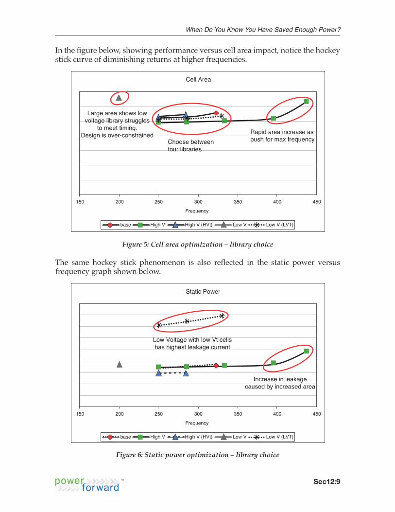
Inthefigurebelow,showingperformanceversuscellareaimpact,noticethehockeystickcurveofdiminishingreturnsathigherfrequencies.
The same hockey stick phenomenon is also reflected in the static power versusfrequencygraphshownbelow.
Cell Area
Frequency
Choose betweenfour libraries
Rapid area increase aspush for max frequency
Large area shows lowvoltage library struggles
to meet timing.Design is over-constrained
300 350 400 450250150 200
base High V High V (HVt) Low V Low V (LVT)
Figure 5: Cell area optimization – library choice
Static Power
Frequency
Low Voltage with low Vt cellshas highest leakage current
Increase in leakagecaused by increased area
300 350 400 450250150 200
base High V High V (HVt) Low V Low V (LVT)
Figure 6: Static power optimization – library choice

When Do You Know You Have Saved Enough Power?
Sec12:10
And the followingfigure showsdynamicpowerand frequency in the contextoflibrarychoices.Note that theeffectof lowvoltagewith lowVtcells iscalledoutin the center section, large red circle, and that the reduction in dynamic power by lowering voltage is shown in the small red circle, also in the center section of thefigure.
Thechoiceofoptimizingforfrequency,area,staticanddynamicpowerisextremelydesigndependentanddependsontheapplicationandtargetmarket.Itwilldependon the device itself; and how the different modes of operation consume different amounts of static and dynamic power.Soasshown,itispossibletomeetfrequencygoalsandoptimizeforeitherstaticordynamicpowerjustbyselectingthecorrectlibrary.Thisisfineifexternallogicalsorunsatsamevoltage.Ifnot,thenlevelshifterswillbeneededonI/Opathsandwerunasimilarflowtothe“quickanddirty”flowusedforPSOevaluation.InFigure7wenotethatdynamicpowercanalsobereducedbytuningthevoltage.Intheexperimentswesawa12%savingsindynamicpower,realizedbyshiftingfromhighvoltagetonominalvoltage,withoutchangingtheoperatingfrequency.Thisrequiresaccesstodifferenttimingandpowercharacterizationsofthelibraries.
Dynamic Power
Frequency
Low Voltage with low Vt cellsgives best dynamic powerDynamic power is equal
despite lower voltage- due to over-constraining
Reduction in dynamic powerjust by lowering voltage
Rapid power increase as push for max frequency
300 350 400 450250150 200
base High V High V (HVt) Low V Low V (LVT)
Figure 7: Dynamic power optimization – library choice

When Do You Know You Have Saved Enough Power?
Sec12:11
ARM Intelligent Energy Manager™ (IEM)Based onwhatwe have just seen, that 12% savings result just by changing thevoltage,theeffectsofDVFScanbeevaluatedtosaveenergyacrossmultipleblocksand for varying modes of operation.Thefigurebelowshowsthreeseparatetasksthathavetobedonebytheprocessor.Itillustratesthatthereisslacktimebetweentasks1,2,and3wherenothingnewneedsto happen. The key concept is to run the design just fast enough to meet application deadlines and no faster.Sosincetheoperatingsystemknowsthedeadlines,itknowsitcantakelongertodoeach task, with the goal of running the task as slow as possible while still meeting performancegoals.WithDVFS,asenabledthoughARMIEM,thedesigncanrunatareducedfrequencyandatareducedvoltage(whichsavepowerduetothevoltage-squaredeffectondynamicpower.)
ThefigurebelowshowsthesamethreetaskswithDVFSusingARMIEM:
• Task1cantakemuchlonger,runningveryslowatamuchlowervoltagewhichisquiteenergy-efficient
• Task2requiresamediumapplicationdeadline,soitcanrunmediumslowwitha slightly reduced voltage and be medium energy-efficient
• Task3requireshighperformancesoarelativelyhighvoltage
Running fast and then idling wastes energy
Task 1 IdleTime
Energy
Voltage
Task 2 Task 3
ReduceVoltage
ReduceVoltage
ReduceVoltage
Only need to run just fast enough to meet the application deadlines
Run Task Slowas Possible
Run Task inAvailable time
Figure 8: Energy without ARM IEM

When Do You Know You Have Saved Enough Power?
Sec12:12
The dotted black line shows the original energy consumed, and the solid black line the energy used when DVFS was enabled.
The net result is energy savings: not power reduction, but energy reduction.The energy benefit labeled at the far right side of the slide shows that the designhas done the same amount of work, with less energy. This translates into the all-important battery life competitive specification.
ARM–Cadence Reference Methodology for ARM1176JZF-S processor with IEM
The ARM-Cadence reference flow for the ARM1176JZF-S processor with IEMdemonstrates howDVFS can be implemented in an automated, top-down flow fromRTL to GDSII.In the case of the ARM1176JZF-S processor, the RTL hierarchy matches powerdomains that are specified in the CPF file, which is also used to indicate where levelshifters and isolation cells should be inserted to the design.The reference flow alsomakes use of the supportwithin SoCEncounter for the tri-lib.ECSM flow. This shows how it is possible to optimize for any voltage by accuratelymodelling the effect of voltage changes on final fimingIt is also worth noting that the introduction of DVFS now enables the processor torun at many speeds, which are dynamically variable. The other logic around the
Running fast and then idling wastes energy
Task 1 IdleTime
EnergySaved
Voltage
Task 2 Task 3
ReduceVoltage
ReduceVoltage
Only need to run just fast enough to meet the application deadlines
Run Task Slowas Possible
Run Task inAvailable time
ReduceVoltage
Figure 9: Energy without ARM IEM

When Do You Know You Have Saved Enough Power?
Sec12:13
processorsmustalsobeabletointerfacewithit.InthecaseoftheARM1176JZF-Sprocessor the AMBA® 3 AXI™ interface supports both a synchronous and an asynchronousmode.Thishandshaking isrequiredandmustbeaddressed in thelogicfunctionalityitselfinordertoimplementDVFS.
ARM1176JZF-S Synthesis Flow Using CPF for DVFS
Easingcomplexity,CPFalsomakesadifferenceinthesynthesisflow.Lookingattheyellowarrows,fromtoptobottom,CPFisusedrespectivelyto:
• Readinlibraries• Definepowerdomains• RunconsistencychecksbetweenRTLandCPF• Insertthelowpowerlogic(commit)• Definereporting,whichisnowdoneperpowermode
HARDENED CORE
ACLK
VRAM
SVC
OR
EVSO
C
TCM and cache RAMS
Clamp Clamp
ARM® core
IEM Sync/Async I/F
L-shift/ClampL-shift/C
lamp
IEM Sync/Async I/F
Figure 10: ARM low-power architecture

When Do You Know You Have Saved Enough Power?
Sec12:14
Asshown,usingDVFSdoesnotaffectthemainbodyoftheflow.Afewsimplestepschangeatthestartandattheend,butthemainsynthesisflowdoesnot.Theconclusion is that theDVFStechnique,whilenotparticularly invasiveto thesynthesisfloworRTLcoding/verification,offersthepotentialforgreatsavings.
Power Savings in Multicore ProcessorsMulticore and Multi-processor Designs
Multicoreprocessorsarebecomingincreasinglycommon.ThelatestprocessorfromARMistheCortex-A9MPCore™ processor, a multi-core design which enables both performance and power improvements over single-core designs.TheCortex-A9processoristhecurrentprojectforjointcollaborationbetweenARMandCadence,anditsarchitectureisshowninthefigurebelow.
read_cpf -library CPF_fileread_hdl $ HDL_fileselaborate
read_cpf CPF_filecheck_cpf -all -detailset_attribute max-leakage-power <value>
synthesize -to_mapped -effort high
connect_scan_chainssynthesize -to_mapped -effort high -incr
commit_cpf
foreach mode { report timing -mode $mode; report power -mode $mode; write_sdc -mode $mode}
Import RTL
Setup MSV, Multi-Mode, and Power Constraints
Top-down synthesisMulti-V / Multi-Mode
Connect scan chains &incremental synthesis
Insert low power logic
Analysis / output
RTL_files.vMulti-voltage*.lib
Multi-vth*.lib
CPF
SDC
SDC
Gate.v
Figure 11: ARM1176JZF-S synthesis flow using CPF for DVFS

When Do You Know You Have Saved Enough Power?
Sec12:15
Similarly, the physical layout of a two-core implementation of the Cortex-A9 isshownbelow,clusteringtheCPU,dataengine,datacache,instructioncache,etc.
Figure 13: Floorplan of two-core build of Cortex-A9 MPCore
Cor
tex
- A9
MPC
ore
ARM CoreSight™ Multicore Debug and Trace Architecture
Advanced Bus Interface Unit
Primary AMBA 3 64bit Interface
GenericInterrupt Controland Distribution
AcceleratorCoherency
Port
Snoop Control Unit (SCU)
Cache-2-CacheTransfers
SnoopFiltering Timers
Optional 2ndI/F with Address Filtering
FPU/NEON
Cortex-A9 CPU
I-Cache D-Cache
PTMI/F FPU/NEON
Cortex-A9 CPU
I-Cache D-Cache
PTMI/F FPU/NEON
Cortex-A9 CPU
I-Cache D-Cache
PTMI/F FPU/NEON
Cortex-A9 CPU
I-Cache D-Cache
PTMI/F
Figure 12: Cortex-A9 MPCore architecture

When Do You Know You Have Saved Enough Power?
Sec12:16
Power Savings in Multi-Processor Designs
Inaholisticapproachtopower,thefirststepistojointlyinvestigatewhichtechniquesshould be applied based on performance and power trade-offs:
• MSVtospeedupcriticalpaths,andsavepowerelsewhere• PSOofindividualcores,whenoverallprocessordemanddrops• DVFSforindividualcores
Theresultingflowsformulti-processordesignsarejointlydevelopedandtestedbybothARMandCadence.ThereisalreadyaCadenceflowforeveryARMprocessor.Thelow-powerIEMenabledARM1176JZF-Sprocessorflowwasreleasedlastyear.NewflowsfortheCortex-M3processorandCortex-A9multicoreprocessorthatuseadvancedlowpowertechniquesarecurrentlybeingjointlydeveloped.
ConclusionsAdding support for advanced low-power design early in the flow can impactthe area, power, performance and success of your designs. Power intent shouldbeconsideredearly,duringRTLcoding.WithCadenceRTLCompilerandCPF,adesignercanquicklyexploretheimpactofdifferentlow-powertechniquestofindthe best solution.Examplesof successfuldeploymentofMSV,PSOandDVFSwerediscussedanddemonstratedonARMprocessors.Quantifiedpower savingswere realizedwithminimal complexity, area or performance tradeoffs. Therisksandcomplexityof lowpower-designare significantlyoffsetbyusingaproduction-proven flow, an example of which is the work done collaborativelybetweenARMandCadence,toprovidelow-powerfunctionalitytothelatestARMprocessors,includingtheCortexfamilyandnewmulti-processordesigns.________________________Acknowledgementsand thanks toARMfor theARMIEM informationandgraphics, and for theirongoingeffortsonthejointCPFflowprojects.
________________________David Weir, Lead Design Engineer, Cadence Design,studiedatEdinburghUniversity,Scotland,wherehereceiveda jointhonorsbachelor’sdegree inComputerScienceandElectronics.HavingusedCadence tools formorethan10years,hehasexperienceinallstagesofdigitaldesign,fromRTLcoding,verification,synthesis,andtestinsertion,throughlayout,timingclosure,andfinalsignofftimingandphysicalchecksrunattapeout.CurrentlyheisworkingonjointprojectswithARM,focusingonhighperformanceflowsfortheirlargestprocessors.

When Do You Know You Have Saved Enough Power?
Sec12:17
Referenceshttp://rtcgroup.com/arm/2007/presentations/134%20%20Demonstrating%20Synthesis%20Techniques%20to%20Implement%20an%20ARM%20Cortex-A8.pdfhttp://www.cdnusers.org/CDNLive/SiliconValley2007Proceedings/tabid/419/Default.aspx?topic=Logic%20Design
http://www.rtcgroup.com/arm/2008/survey/presentations/52%20-%20Revealing_the_Low_Power_Techniques_You_Should_use_With_ARM_Cortex_Processors.pdf
http://www.rtcgroup.com/arm/2008/survey/presentations/65%20-%20Optimizing_the_Performance_of_a_Low_Power_ARM_Cortex-A9.pdf
The CDNLive presentation will be available online at some point in the future. Currently it is only available to folks who attended the conference…
