16
LPOL-cavity • Introduction • Tests at Orsay • Optics (laser polarisation) • Calorimeter DAQ • Mechanics & installation at DESY Norbert’s talk
| Date post: | 01-Jan-2016 |
| Category: |
Documents |
| Upload: | melissa-sophie-pope |
| View: | 214 times |
| Download: | 0 times |
LPOL-cavity• Introduction
• Tests at Orsay
• Optics (laser polarisation)
• Calorimeter DAQ
• Mechanics & installation at DESY Norbert’s talk
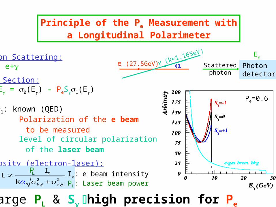
Principle of the Pe Measurement witha Longitudinal Polarimeter
Compton Scattering: e+ e+
Cross Section: d/dE = 0(E) - PeS1(E)
0, 1: known (QED) Pe: Polarization of the e beam to be measured S: level of circular polarization of the laser beam
Luminosity (electron-laser): e
2 2e,y ,y
L IL
k
P
e (27.5GeV) (k=1.165eV)
E
Photondetector
Ie: e beam intensityPL: Laser beam power
Scatteredphoton
Pe=0.6
Large PL & Shigh precision forPe

Fabry-Perot cavity: principle
e beam
Polar.Lin.
Polar.Circ.
When Laser =0 c/2L resonance
L
•But : /Laser = 10-11 laser/cavity feedback
•Done by changing the laser frequency
Laser: Nd:YAG (infrared, =1064 nm)
Gain 8000
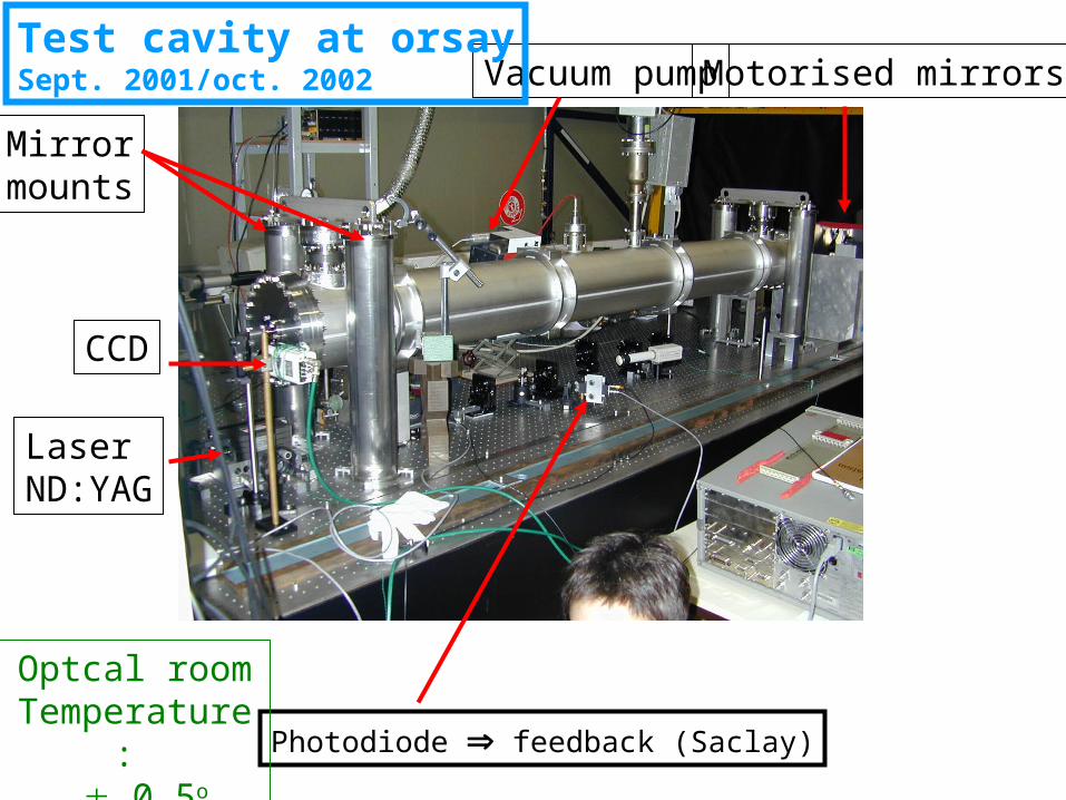
Photodiode feedback (Saclay)
Laser ND:YAG
Mirrormounts
Motorised mirrors
CCD
Vacuum pump
Optcal roomTemperature:
0.5o
Test cavity at orsaySept. 2001/oct. 2002
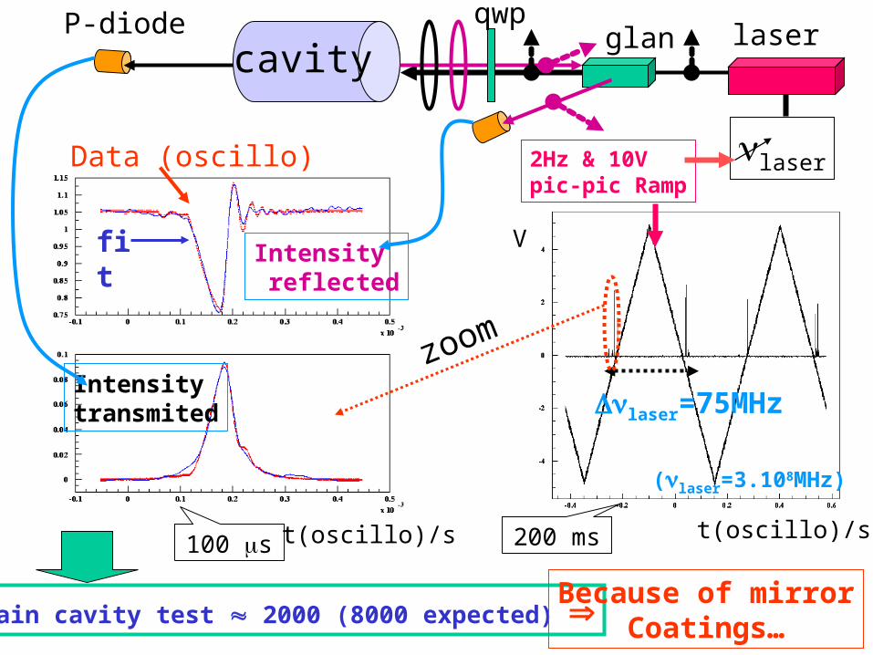
V
2Hz & 10V pic-pic Ramp
Intensitytransmited laser=75MHz
t(oscillo)/s
zoom
t(oscillo)/s
Intensity reflected
100 s
laserglancavity
P-diode
200 ms
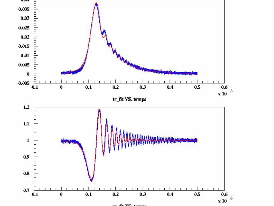
fit
Data (oscillo) laser
gain cavity test 2000 (8000 expected)
(laser=3.108MHz)
Because of mirrorCoatings…
qwp

Hera plane is notHorizontal …
Final cavity Orsay: Oct. 2002/feb.2003
e beam
Ellipsometer

Results with final cavity at Orsay
•Mirrors movable from outside cavity mirrors quality not homogeneous
cavity gain is now >7000•BUT:
•only 65%-70% on the laser incident power is coupled to the cavity
•under investigation: we suspect the laser linewidth ( 5kHz for 1ms % Cavity bandwith 3kHz for 0.05ms)
Power inside cavity: 65% * 7000* 700mW 3200W

TransmittedPower % time
Reflected power % time
Gain estimated by Christian’s fits:
Good agreement impossible without laser linewidth

•Cavity gain via cavity decay time (V. Soskov):
•laser pumping diode switched off when cavity is locked•transmitted power measured as function of time
The biggest the power inside cavity, the higher the decay time ( formula…)
1rst test cavity
1rst & 2nd tryWith final vavity
Best with testcavity
cavity
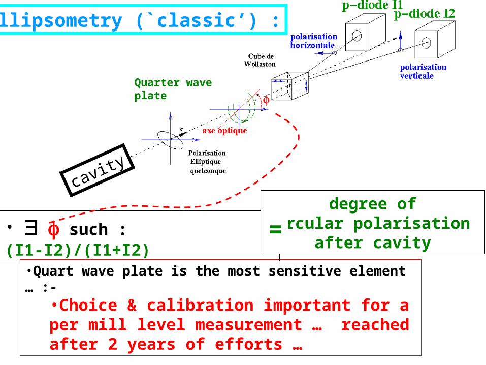
•Quart wave plate is the most sensitive element … :-
•Choice & calibration important for a per mill level measurement … reached after 2 years of efforts …
Ellipsometry (`classic’) :
• such : (I1-I2)/(I1+I2)
degree ofcircular polarisation
after cavity=
Quarter wave plate

Temp. controlled p-diodeElectronics (Peletier module)
ccd
QWP
HBSBeam splitter
wollaston3 InGaAs p-diodes
Laser beamafter cavity
Beam shutter(p-diodes pedestals)
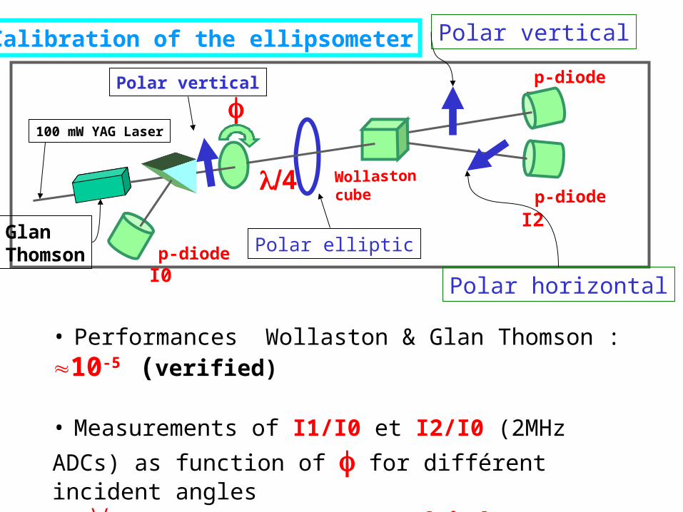
100 mW YAG Laser
Wollaston cube
4
p-diode I1
p-diode I2
Glan Thomson
Polar vertical
Calibration of the ellipsometer
p-diode I0
• Performances Wollaston & Glan Thomson : 10-5 (verified)
• Measurements of I1/I0 et I2/I0 (2MHz ADCs) as function of
for différent incident angles
fit no, ne & thickness
Polar horizontal
Polar vertical
Polar elliptic
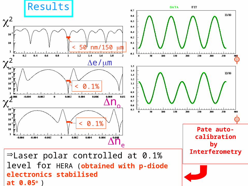
e/m
2
2
2
ne
no
< 0.1%
< 0.1%
< 50 nm/150 m
Results
Laser polar controlled at 0.1% level for HERA (obtained with p-diode electronics stabilisedat 0.05o )
Pate auto-calibration
by Interferometry

Calorimeter readout
•Same system as H1-Lumi calo readout but
•RIO card with 1 Mb MFCC L2 cache memory (polarisation for all bunches 10MHz)
•MFCC FPGA Programming is done and tested•Histogramming in the L2 cache is being programmed •The slow control part (PVSS+LabView) is also being programmed

Conclusions
• Feedback and cavity gain– Work fine, power inside cavity also fine:
70%*8000*700mW=4000W
• Laser polarisation– Per mill level reached after 2 years of
work…• Calo. DAQ should be ready before
the end of the shutdown• Laser is being aligned and locking …