REPIC Corporation GMW Associates28-3, Kita Otsuka 1-Chome 955 Industrial RoadToshima-ku, Tokyo 170-0004 San Carlos, CA 94070Tel.: 03 - 3918 - 5326 Tel.: (650) 802-8292Fax: 03 - 3918 - 5712 Fax: (650) [email protected][email protected]
BERGOZ Instrumentation - 01630 Saint Genis Pouilly, France - Tel.: +33-450.426.642 - Fax: [email protected] - http://www.bergoz.com - Registre des Métiers: Bourg-en-Bresse - Registre des ingénieurs: Zurich
TVA-VAT-IVA-USt. Nº FR88414997130 - Sàrl. capital 152K€ - Siren 414 997 130 R.C.S. Bourg - APE 332B
Log-ratioBeam Position Monitor
User’s Manual
Record of updates
Version Release date
2.2.1 April 28, 2008
p.35 CONNECTORS PINS ALLOCATION Rev. 2.1Optional output signals: LogA, LogB, LogC and LogDpin assignment on DIN41612M LR-BPM module rear connectorhas been corrected to resp. b31*, b223, b28* and B25*.Note to users of BPM-RFC chassis with BPM-RFC/ABCD option: The locations of chassis rear panel SMA output connectors LogA, LogB, LogC and LogD are unchanged.
SUMMARYPage
INITIAL INSPECTION ................................................................................................. 2WARRANTY ................................................................................................................ 2ASSISTANCE ............................................................................................................... 2SERVICE & RETURN PROCEDURES ...................................................................... 2YOU JUST RECEIVED A BPM POSITION MONITOR... ........................................ 3
Determine which LR-BPM model you received................................................. 4MODES OF OPERATION FOR VARIOUS BEAMS................................................... 6
Sample & Hold (S&H) Mode........................................................................... 6Track & Hold (T&H) Mode.............................................................................. 6Track-Continuous (T) Mode.............................................................................. 6
OPTIONS........................................................................................................................ 7Built-in Beam Trigger option............................................................................. 7Sum of Logs option........................................................................................... 7Direct log output for A, B, C and D.................................................................... 7
ACCESS to JUMPERS, STRAPS and SWITCHES....................................................... 8SAMPLE & HOLD MODE............................................................................................ 9TRACK & HOLD MODE............................................................................................... 10TRACK-CONTINUOUS MODE................................................................................... 11CHANGING PICKUP CONFIGURATION.................................................................. 12
BERGOZ Instrumentation Log-ratio Beam Position Monitor01630 Saint Genis Pouilly, France Version 2.2.1Tel. +33-450.426.642 includes Sample & Hold optionFax +33-450.426.643 Page 1 User’s manual
INITIAL INSPECTION
It is recommended that the shipment be inspected immediately upon delivery. If it is damaged in any way, contact Bergoz Instrumentation or your local distributor. The content of the shipment should be compared to the items listed on the invoice. Any discrepancy should be notified to Bergoz Instrumentation or its local distributor immediately. Unless promptly notified, Bergoz Instrumentation will not be responsible for such discrepancies.
WARRANTY
Bergoz Instrumentation warrants its beam monitors to operate within specifications under normal use for a period of 12 months from the date of shipment. Spares, repairs and replacement parts are warranted for 90 days. Products not manufactured by Bergoz Instrumentation are covered solely by the warranty of the original manufacturer. In exercising this warranty, Bergoz Instrumentation will repair, or at its option, replace any product returned to Bergoz Instrumentation or its local distributor within the warranty period, provided that the warrantor's examination discloses that the product is defective due to workmanship or materials and that the defect has not been caused by misuse, neglect, accident or abnormal conditions or operations. Damages caused by ionizing radiations are specifically excluded from the warranty. Bergoz Instrumentation and its local distributors shall not be responsible for any consequential, incidental or special damages.
ASSISTANCE
Assistance in installation, use or calibration of Bergoz Instrumentation beam monitors is available from Bergoz Instrumentation, 01630 Saint Genis Pouilly, France. It is recommended to send a detailed description of the problem by fax.
SERVICE PROCEDURE
Products requiring maintenance should be returned to Bergoz Instrumentation or its local distributor. Bergoz Instrumentation will repair or replace any product under warranty at no charge. The purchaser is only responsible for transportation charges.
For products in need of repair after the warranty period, the customer must provide a purchase order before repairs can be initiated. Bergoz Instrumentation can issue fixed price quotations for most repairs. However, depending on the damage, it may be necessary to return the equipment to Bergoz Instrumentation to assess the cost of repair.
RETURN PROCEDURE
All products returned for repair should include a detailed description of the defect or failure, name and fax number of the user. Contact Bergoz Instrumentation or your local distributor to determine where to return the product. Returns must be notified by fax prior to shipment.
Return should be made prepaid. Bergoz Instrumentation will not accept freight-collect shipment. Shipment should be made via United Parcel Service, DHL or Federal Express. Within Europe, the transportation service offered by the Post Offices "EMS" (Chronopost, Datapost, etc.) can be used. The delivery charges or customs clearance charges arising from the use of other carriers will be charged to the customer.
BERGOZ Instrumentation Log-ratio Beam Position Monitor01630 Saint Genis Pouilly, France Version 2.2.1Tel. +33-450.426.642 includes Sample & Hold optionFax +33-450.426.643 Page 2 User’s manual
YOU JUST RECEIVED A BEAM POSITION MONITOR ....
This manual applies to the Log-ratio BPM only: LR-BPMOther models, e.g. “BPM”, “MX-BPM”, “VF-BPM”, “BB-BPM” are described in other manuals.
The Log-ratio BPM system includes:
Description Order code
• Log-ratio BPM electronics module LR-BPM-XXXMHz• Sample & Hold on X and Y, option LR-BPM-SH• Beam Trigger, option LR-BPM-TRG• Sum of logs, option LR-BPM-SUM• Direct A,B,C,D wideband outputs, option LR-BPM-ABCD
The options are factory-installed on the LR-BPM electronics module.
Accessories• Beam-Based Center determination module BPM-BBC• 19” chassis with power supply BPM-RFC/X, X = BPM stations number• Table-top test kit with power supply BPM-KIT• 3U-Card extender with coaxial contacts BPM-XTD• RF service module with four front-panel BNC BPM-SERV/RF• TTL commands service module BPM-SERV/CMD
with front-panel DB9 and DB15 connectors
Check the power supply voltage, that it corresponds to your mains voltage.
On some table-top kit BPM-KIT older models, an AC/DC power supply blockis installed. Its AC input voltage range is indicated on the power supply block. If it does not correspond to your AC mains, use a transformer or contact the manufacturer to get another power supply.In the 19” chassis BPM-RFC: The power supply is autoranging from 98V…264V.
Check the fuse configuration, that it corresponds to your national regulations.
The table-top test kit does not have any fuse.The 19” BPM-RFC chassis fuse compartment is configured at the time of shipment according to its destination:• North America: mains ground wire unfused.• All other destinations: both mains wires are fused.To verify which fuse configuration is installed on your chassis, pull out the removable fuse block, using a small screwdriver. • The unfused ground configuration has a shorting bar and a 2A 6x32 fuse.• The configuration with both AC lines fused is equipped with two 2A 5x20 fuses.To change this configuration, unscrew the fuse holder off the fuse block, flip the holder over and screw it back onto the fuse block. Insert the following fuses:• For unfused ground configuration: one 2A 6x32 fast fuse.• For both AC lines fused configuration: two 2A 5x20 fast fuses.
BERGOZ Instrumentation Log-ratio Beam Position Monitor01630 Saint Genis Pouilly, France Version 2.2.1Tel. +33-450.426.642 includes Sample & Hold optionFax +33-450.426.643 Page 3 User’s manual
YOU JUST RECEIVED A BEAM POSITION MONITOR ....Determine which LR-BPM model you received
LR-BPM version-1 have serial numbers < #955. They are described in another manual.If you have a Version-1 unit, please ask Bergoz Instrumentation or your distributor to send the LR-BPM User’s Manual version 1.x.
LR-BPM version-2.0 have serial numbers #956 ≤ SN ≤ #1074The circuit revision number 111.2.0 is engraved on the printed circuit board “solder side”.LR-BPM version-2.0 are the object of this User’s Manual.
LR-BPM version 2.1 are the object of this manualLR-BPM version-2.1 have serial numbers SN ≥ #1092The circuit revision number 111.2.1 is engraved on the printed circuit board.LR-BPM version-2.1 with Sample & Hold option LR-BPM-SH can be recognized by:• The printed circuit is equipped with Track&Hold + Sample&Hold circuits:
Track&Hold + Sample&Hold circuits
BERGOZ Instrumentation Log-ratio Beam Position Monitor01630 Saint Genis Pouilly, France Version 2.2.1Tel. +33-450.426.642 includes Sample & Hold optionFax +33-450.426.643 Page 4 User’s manual
YOU JUST RECEIVED A BEAM POSITION MONITOR ....Determine which LR-BPM model you received (Cont’d)
LR-BPM version-2.1 with Beam Trigger option LR-BPM-TRG can be recognized by:• The printed circuit board is equipped with a log amplifier limiter circuit:
Beam Trigger circuit
LR-BPM version-2.1 with A,B,C and D direct outputs option LR-BPM-ABCD can be recognized • The printed circuit board is equipped with A, B, C and D output connectors:
Direct output connectors for Channels A, B, C and D
BERGOZ Instrumentation Log-ratio Beam Position Monitor01630 Saint Genis Pouilly, France Version 2.2.1Tel. +33-450.426.642 includes Sample & Hold optionFax +33-450.426.643 Page 5 User’s manual
MODES OF OPERATION FOR VARIOUS BEAMS
LR-BPM can be equipped with many options, then further configured by the user to support many modes of operation:
Sample & Hold (S&H) Mode
Requires Sample&Hold option LR-BPM-SH to be mounted on the printed circuit board
Processing time ~450 nsHold time Up to 100 ms. ADC measurement time At maximum repetion rate, at least 100 ns “good” signalRepetition rate Up to 2 MHz
Indicated for: Linacs: single bunch, bunch trains, prebunched S-band/X-bandTransfer linesSynchrotron first turnSynchrotron single bunch turn-by-turnSynchrotron multi-single bunch turn-by-turn, using trigger gate.
Refer to “Sample & Hold Mode” for switch settings
Track & Hold (T&H) Mode
Requires Sample&Hold option LR-BPM-SH to be mounted on the printed circuit board
Processing time ~110 nsHold time ~70 nsADC measurement time At maximum repetion rate, at least 50 ns “good” signalRepetition rate Up to 5 MHz
Indicated for: Synchrotron 2 MHz < ƒrev < 5 MHz, single bunch turn-by-turnSynchrotron multi-single bunch turn-by-turn, using trigger gate.
Refer to Track & Hold Mode” for switch settings
Track Continuous (T) Mode
Does not require Sample & Hold optionDoes not require Built-in Beam Trigger option
Output bandwidth 5 MHz
Indicated for: CW beams in general:• Linacs and synchrotrons with bunch repetition rate up to 500 MHz• Betatron oscillation monitoring in boosters and storage rings• L-band, S-band, X-band linacs prebunched up to 500 MHz• Smaller-size ion and proton synchrotrons with ƒrev > 5 MHz.
Refer to “Track-Continuous Mode” for switch settings.
BERGOZ Instrumentation Log-ratio Beam Position Monitor01630 Saint Genis Pouilly, France Version 2.2.1Tel. +33-450.426.642 includes Sample & Hold optionFax +33-450.426.643 Page 6 User’s manual
MODES OF OPERATION FOR VARIOUS BEAMS (Cont’d)
In Sample&Hold (S&H) and Track&Hold (T&H) modes, LR-BPM must be triggered.
Triggering can be provided:
a) by the built-in Beam Trigger, if installed on LR-BPM (order code LR-BPM-TRG).To use the built-in Beam Trigger, it must be enabled by its switch.See TRG switch below.
b) by an external signal applied to TG.IN.AUX input. To use the external trigger, the built-in trigger –if installed– must be disabled.See TRG switch below.
OPTIONS
In addition to the Sample & Hold option described in the preceding chapter, other options are available:
Built-in Beam Trigger “LR-BPM-TRG” option
Requires Built-in Beam Trigger option LR-BPM-TRG to be mounted on the printed circuit board
Particle polarity LR-BPM version 2.1 operates with positive and negative particle polarity
Minimum detected charge 100 pC bunch seen by four pickups of 5 pf capacitance andwidth = 1/8 of circumference.
Maximum repetition rate 5 MHz.
Sum of logs Output “LR-BPM-SUM” option
Requires Sum-of-Logs option LR-BPM-SUM to be mounted on the printed circuit board
Value SUM = Lg(A) + Lg(B) + Lg(C) + Lg(D)Bandwidth 5 MHzSee typical Lg(A) output from a single bunch on preceding page timing diagram
Direct log outputs for A, B, C and D “LR-BPM-ABCD” option
Requires Direct A,B,C,D Outputs option LR-BPM-ABCD to be mounted on the printed circuit board
Note: Mating connectors are not installed in chassis BPM-RFC orBPM-KIT. Users of option LR-BPM-ABCD must provide theseconnectors. Refer to “BPM MODULE REAR CONNECTOR”.
See typical Lg(A) output from a single bunch on preceding page timing diagram
Note: Accessories are described in a specific chapter “ACCESSORIES”.
BERGOZ Instrumentation Log-ratio Beam Position Monitor01630 Saint Genis Pouilly, France Version 2.2.1Tel. +33-450.426.642 includes Sample & Hold optionFax +33-450.426.643 Page 7 User’s manual
ACCESS to STRAPS and SWITCHES
To access switches or straps, remove the module shield:
To remove shield: Remove screws (2) from underside
LR-BPM modules can be inserted/removed while the power is ON.
The LR-BPM module is equipped with many on-board potentiometers to adjust the log amplifiers gain, slope and intercept point. They require precise instruments, tools and procedures for their adjustment.
BERGOZ Instrumentation Log-ratio Beam Position Monitor01630 Saint Genis Pouilly, France Version 2.2.1Tel. +33-450.426.642 includes Sample & Hold optionFax +33-450.426.643 Page 8 User’s manual
SAMPLE & HOLD MODEMode: Sample&Hold (DOWN)
Set switches to: Processing: Sample&Hold (LEFT position)Timing: Sample&Hold (LEFT position)Built-in Beam Trigger: As desiredADC Trigger Output Edge: As desired
ProcessingLEFT / RIGHT
S&H / T&H
Built-inBeamTrigger
DOWN:Disabled
UP:Enabled
ADCTriggerEdgePolarity
LEFT:Positive
RIGHT:Negative
ModeDOWN / UP
S&H -or- T&H / Track-Continuous
TimingLEFT :S&H
RIGHT:T&H
Timing
LEFT :S&H
RIGHT:T&HStrap-D:OFF for longer delay beforesampling
BERGOZ Instrumentation Log-ratio Beam Position Monitor01630 Saint Genis Pouilly, France Version 2.2.1Tel. +33-450.426.642 includes Sample & Hold optionFax +33-450.426.643 Page 9 User’s manual
TRACK & HOLD MODEMode: Track&Hold (DOWN)
Set switches to: Processing: Track&Hold (RIGHT position)Timing: Track&Hold (RIGHT position)Built-in Beam Trigger: As desiredADC Trigger Output Edge: As desired
ProcessingLEFT / RIGHT
S&H / T&H
ADCTriggerEdgePolarity
LEFT:Positive
RIGHT:Negative
ModeDOWN / UP
S&H -or- T&H / Track-Continuous
TimingLEFT:S&H
RIGHT:T&H
Built-inBeamTrigger
DOWN:Disabled
UP:EnabledTiming
LEFT:S&H
RIGHT:T&HStrap-D:OFF for longer delay beforesampling
BERGOZ Instrumentation Log-ratio Beam Position Monitor01630 Saint Genis Pouilly, France Version 2.2.1Tel. +33-450.426.642 includes Sample & Hold optionFax +33-450.426.643 Page 10 User’s manual
TRACK-CONTINUOUS MODEMode: Track-Continuous (UP)
Set switches to: Processing: Track&Hold (RIGHT position)Timing: Choose suitable position according to
ADCBuilt-in Beam Trigger as desiredADC Trigger Output Edge as desired
ProcessingLEFT / RIGHT
S&H / T&H
Built-inBeamTrigger
DOWN:Disabled
UP:Enabled
ADCTriggerEdgePolarity
LEFT:Positive
RIGHT:Negative
ModeDOWN / UP
S&H -or- T&H / Track-Continuous
TimingLEFT:S&H
RIGHT:T&H
Timing
LEFT:S&H
RIGHT:T&H
Note: Built-in Beam Trigger (Option LR-BPM-TRG) will not operate above 5 MHz bunch repetition rate
Output signals XOUT and YOUT track the position given by A, B, C and D inputs with 5 MHz bandwidth.
BERGOZ Instrumentation Log-ratio Beam Position Monitor01630 Saint Genis Pouilly, France Version 2.2.1Tel. +33-450.426.642 includes Sample & Hold optionFax +33-450.426.643 Page 11 User’s manual
CHANGING PICKUP CONFIGURATION
The pickup configuration is set with two jumpers.To change the configuration from “Rotated” to “Orthogonal” or vice versa, change the jumper position:
Rotated pickups, position of jumpers
Jumpersposition for“Rotated”pickups
Orthogonal pickups, position of jumpers
Jumpersposition for“Orthogonal”pickups
BERGOZ Instrumentation Log-ratio Beam Position Monitor01630 Saint Genis Pouilly, France Version 2.2.1Tel. +33-450.426.642 includes Sample & Hold optionFax +33-450.426.643 Page 12 User’s manual
QUICK CHECK: LR-BPM in Sample&Hold Mode
This Quick Check works only if Sample & Hold LR-BPM-SH option is installed
Unless otherwise specified on the Certificate of Calibration, LR-BPM with Sample&Hold option has following ex-factory settings: • Rotated pickups
BERGOZ Instrumentation Log-ratio Beam Position Monitor01630 Saint Genis Pouilly, France Version 2.2.1Tel. +33-450.426.642 includes Sample & Hold optionFax +33-450.426.643 Page 13 User’s manual
QUICK CHECK: LR-BPM in Sample&Hold Mode (Cont'd)
Attach the equipment together as shown above.
Set the fast pulse generator to:Output voltage: 50V (in 50-ohm)Pulse polarity: negativePulse width ≤ 1 ns fwhmPulse repetition: slow (in the Hz to kHz range)
Please note that signals applied to LR-BPM inputs will be attenuated by the 4-way splitter:Transformer-type 4-way splitters typically attenuate by 7dB,4-way resistive splitters, or cascaded 2-way splitters attenuate by 12dB.
This 50V pulse, after splitting in a transformer-type 4-way splitter (-7 dB) is about equivalent to a 10-nC bunch seen by four pickups of 5 pf capacitance and width = 1/8 of circumference.
Use 4 similar attenuators, each 3 dB. The same test can be done with 5 and 10 dB.Please note that attenuators are seldom more precise than ±0.1 dB. This will be reflected uponthe LR-BPM X and Y zero readings.
Connect to Test Kit or 19” BPM-RFC chassis to AC mains.
Auxiliary trigger output
Observe the Auxiliary trigger from LR-BPM. This trigger is used for oscilloscope triggering.
Input signal fromFast Pulse generator(50 Ω):
Output DB9 pin 9TRG.OUT.AUX(1-MΩ):
Trigger TRG.OUT.AUXcomes ~13 ns after bunch
Ground from DB9 pin 4
BERGOZ Instrumentation Log-ratio Beam Position Monitor01630 Saint Genis Pouilly, France Version 2.2.1Tel. +33-450.426.642 includes Sample & Hold optionFax +33-450.426.643 Page 14 User’s manual
QUICK CHECK: LR-BPM in Sample&Hold Mode (Cont'd)
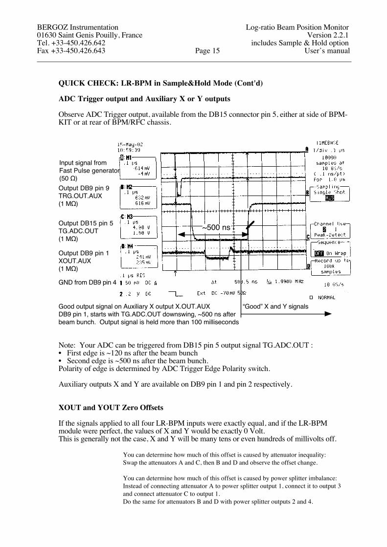
ADC Trigger output and Auxiliary X or Y outputs
Observe ADC Trigger output, available from the DB15 connector pin 5, either at side of BPM-KIT or at rear of BPM/RFC chassis.
Good output signal on Auxiliary X output X.OUT.AUXDB9 pin 1, starts with TG.ADC.OUT downswing, ~500 ns after beam bunch. Output signal is held more than 100 milliseconds
~500 ns
“Good” X and Y signals
Input signal fromFast Pulse generator(50 Ω)Output DB9 pin 9TRG.OUT.AUX(1 MΩ)
Output DB15 pin 5TG.ADC.OUT(1 MΩ)
Output DB9 pin 1XOUT.AUX(1 MΩ)
GND from DB9 pin 4
Note: Your ADC can be triggered from DB15 pin 5 output signal TG.ADC.OUT :• First edge is ~120 ns after the beam bunch• Second edge is ~500 ns after the beam bunch.Polarity of edge is determined by ADC Trigger Edge Polarity switch.
Auxiliary outputs X and Y are available on DB9 pin 1 and pin 2 respectively.
XOUT and YOUT Zero Offsets
If the signals applied to all four LR-BPM inputs were exactly equal, and if the LR-BPM module were perfect, the values of X and Y would be exactly 0 Volt.This is generally not the case, X and Y will be many tens or even hundreds of millivolts off.
You can determine how much of this offset is caused by attenuator inequality: Swap the attenuators A and C, then B and D and observe the offset change.
You can determine how much of this offset is caused by power splitter imbalance: Instead of connecting attenuator A to power splitter output 1, connect it to output 3and connect attenuator C to output 1.Do the same for attenuators B and D with power splitter outputs 2 and 4.
BERGOZ Instrumentation Log-ratio Beam Position Monitor01630 Saint Genis Pouilly, France Version 2.2.1Tel. +33-450.426.642 includes Sample & Hold optionFax +33-450.426.643 Page 15 User’s manual
QUICK CHECK: LR-BPM in Sample&Hold Mode (Cont'd)
Simulating beam position changes
To simulate beam position changes, the input signal power is changed by 6 dB, 10 dB and 14 dB, hence simulating position changes up to 1/3 of vacuum chamber radius.
The pulse generator output amplitude should be in the range 5V..50VThe LR-BPM on-center sensitivity is factory-set to 55.5 mV per dB of signal difference between opposite pickups. For pickups with small angle (e.g. buttons), 6 dB corresponds to beam displacement equal to 1/6 of vacuum chamber radius. As the beam goes far off center, this sensitivity becomes lower due to the algorithm X = Log (A/C). Please consider that the pickup sensitivity becomes higher as the beam goes off center, and one non-linearity tends to compensate the other.
Before simulating a beam displacement, start by noting the X and Y zero offsets, using fourequal attenuators:
Powersplitter
Fast PulseGenerator
ABCD
Then simulate the displacement by removing an attenuator from one input and inserting it in the opposite input: A <=> C, and B <=> D.Example:
Powersplitter
ABCD
Fast PulseGenerator
Attenuator C is removed from input C, and added to input A, thus simulating a displacement of the beam towards C (stronger signal on C pickup).
LR-BPM modules are factory preset :• For orthogonally placed pickups: up, down, left and right
Or,• For rotated pickups: upper-right, upper-left, lower-left and lower-right.
The combinations on the following table can be tried, yielding the X and Y values listed.
Please note these are displacements. Take into consideration the zero offsets due to power splitter imbalance and attenuators inequality.
BERGOZ Instrumentation Log-ratio Beam Position Monitor01630 Saint Genis Pouilly, France Version 2.2.1Tel. +33-450.426.642 includes Sample & Hold optionFax +33-450.426.643 Page 16 User’s manual
QUICK CHECK: LR-BPM in Sample&Hold Mode (Cont'd)
Simulating beam position changes (Cont’d)
Table of X/Y output voltage vs. input amplitude
Input Attenuators Equivalent displacement Rotated pickups Orthogonal pickupsA 3 + 3 1/6 of radius towards CB 3 X = -0.245 V X = -0.347 VC 0 Y = -0.245 V Y = 0 VD 3 (button pickups << chamber diameter)(button pickups << chamber diameter)
A 3 + 3 1/6 of radius towards CB 3 + 3 1/6 of radius towards D X = 0 V X = -0.347 VC 0 Y = -0.490 V Y = -0.347 VD 0 (button pickups << chamber diameter)(button pickups << chamber diameter)
A 5 + 5 1/4 of radius towards CB 5 X = -0.407 V X = -0.576 VC 0 Y = -0.407 V Y = 0 VD 5 (button pickups << chamber diameter)(button pickups << chamber diameter)
A 5 + 5B 5 + 5 X = 0 V X = -0.576 VC 0 Y = -0.814 V Y = -0.576 VD 0 (button pickups << chamber diameter)(button pickups << chamber diameter)
A 10 + 7 1/3 of radius towards CB 10 X = -0.570 V X = -0.806 VC 3 Y = -0.570 V Y = 0 VD 10 (button pickups << chamber diameter)(button pickups << chamber diameter)
Please note these are displacements. Take into consideration the zero offsets due to power splitter imbalance and attenuators inequality.
BERGOZ Instrumentation Log-ratio Beam Position Monitor01630 Saint Genis Pouilly, France Version 2.2.1Tel. +33-450.426.642 includes Sample & Hold optionFax +33-450.426.643 Page 17 User’s manual
QUICK CHECK: LR-BPM in Sample&Hold Mode (Cont'd)
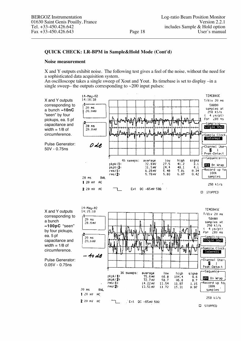
Noise measurement
X and Y outputs exhibit noise. The following test gives a feel of the noise, without the need for a sophisticated data acquisition system.An oscilloscope takes a single sweep of Xout and Yout. Its timebase is set to display –in a single sweep– the outputs corresponding to ~200 input pulses:
X and Y outputs corresponding to a bunch ~10nC “seen” by four pickups, ea. 5 pf capacitance and width = 1/8 of circumference.
Pulse Generator:50V - 0.75ns
X and Y outputs corresponding to a bunch ~100pC “seen” by four pickups, ea. 5 pf capacitance and width = 1/8 of circumference.
Pulse Generator:0.05V - 0.75ns
BERGOZ Instrumentation Log-ratio Beam Position Monitor01630 Saint Genis Pouilly, France Version 2.2.1Tel. +33-450.426.642 includes Sample & Hold optionFax +33-450.426.643 Page 18 User’s manual
QUICK CHECK: LR-BPM in Track&Hold Mode
This Quick Check works only if LR-BPM-SH (Sample & Hold) option is installed.
LR-BPM ordered specifically for Track&Hold operation has following ex-factory settings:• Rotated pickups
BERGOZ Instrumentation Log-ratio Beam Position Monitor01630 Saint Genis Pouilly, France Version 2.2.1Tel. +33-450.426.642 includes Sample & Hold optionFax +33-450.426.643 Page 19 User’s manual
QUICK CHECK: LR-BPM in Track&Hold Mode (Cont’d)
Attach the equipment together as shown above. Set the fast pulse generator to:• Output voltage: 50V (in 50-ohm)• Pulse polarity: negative• Pulse width ≤ 1 ns fwhm• Pulse repetition: slow (in the Hz to kHz range).
Please note that signals applied to LR-BPM inputs will be attenuated by the 4-way splitter:Transformer-type 4-way splitters typically attenuate by 7dB,4-way resistive splitters, or cascaded 2-way splitters attenuate by 12dB.
This 50V pulse, after splitting in a transformer-type 4-way splitter (-7 dB) is about equivalent to a 10-nC bunch seen by four pickups of 5 pf capacitance and width = 1/8 of circumference.
Use 4 similar attenuators, each 3 dB. The same test can be done with 5 and 10 dB.Please note that attenuators are seldom more precise than ±0.1 dB. This will be reflected uponthe LR-BPM X and Y zero readings.
Connect to Test Kit or 19” BPM-RFC chassis to AC mains.
Observe the traces from:• Auxiliary trigger output: ~13 ns after bunch. This output is used for oscilloscope triggering.• Trigger output for ADC: 110 ns after the bunch. This trigger is used to trigger ADC.• X or Y output: signal can be measured; it is held for ~70 ns.
Next, proceed thru the same tests as “QUICK CHECK: LR-BPM in Sample & Hold Mode”:• XOUT and YOUT Zero Offsets• Simulating beam position changesNoise measurement cannot be performed as easily in Track&Hold mode, because the output signal is held only ~70ns. For noise measurement, X or Y output must be sampled, using either Auxiliary Trigger, or ADC Trigger.
BERGOZ Instrumentation Log-ratio Beam Position Monitor01630 Saint Genis Pouilly, France Version 2.2.1Tel. +33-450.426.642 includes Sample & Hold optionFax +33-450.426.643 Page 20 User’s manual
QUICK CHECK: LR-BPM in Track-Continuous Mode
If you wish to use an LR-BPM (whether or not it has the Sample & Hold option LR-BPM-SH), its switches must be set to according to chapter TRACK-CONTINUOUS MODE. Unless otherwise specified, LR-BPM without Sample&Hold LR-BPM-SH option has following ex-factory settings: • Rotated pickups
BERGOZ Instrumentation Log-ratio Beam Position Monitor01630 Saint Genis Pouilly, France Version 2.2.1Tel. +33-450.426.642 includes Sample & Hold optionFax +33-450.426.643 Page 21 User’s manual
QUICK CHECK: LR-BPM in Track-Continuous Mode (Cont'd)
To display X and Y signals, you can use either two DVMs, or an oscilloscope.Attach the equipment together as shown above.
Set the DVMs on Volt-DC, or the oscilloscope on:Time base on 0.2 ms / div., free running,Channel 1 to Xout signal, sensitivity 0.2 V / div., 1 MΩ DC couplingChannel 2 to Yout signal, sensitivity 0.2 V / div., 1 MΩ DC coupling
Set the RF source to the LR-BPM operating frequency.E.g. set to 500 MHz to test LR-BPM-500MHz.Amplitude ca. -10 dBm
Use 4 similar attenuators, each 3 dB. The same test can be done with 5 and 10 dB.Please note that attenuators are seldom more precise than ±0.1 dB. This will be reflected uponthe LR-BPM X and Y readings.
Please note that signals applied to LR-BPM inputs will be attenuated by the 4-way splitter:Transformer-type 4-way splitters typically attenuate by 7dB,4-way resistive splitters, or cascaded 2-way splitters attenuate by 12dB.
Connect to Test Kit or 19” BPM-RFC chassis to AC mains, the DVM (or oscilloscope) will display X and Y values.If the RF signals applied to all four LR-BPM inputs were exactly equal, and if the LR-BPM module were perfect, the values of X and Y would be exactly 0 Volt.This is generally not the case, X and Y will be many 10s or even 100s of millivolts off.
You can determine how much of this offset is caused by attenuator inequality: Swap the attenuators A and C, then B and D and observe the offset change.
You can determine how much of this offset is caused by power splitter imbalance: Instead of connecting attenuator A to power splitter output 1, connect it to output 3and connect attenuator C to output 1.Do the same for attenuators B and D with power splitter outputs 2 and 4.
The next tests will consist of:
• Simulating beam displacements of 6 dB, 10 dB and 14 dB• Exploring the LR-BPM dynamic range by varying the RF source output power.
Beam displacement
The RF source output power should be in the range -10dBm ... -35 dBm
The LR-BPM on-center sensitivity is factory-set to 55.5 mV per dB of signal difference between opposite pickups. For pickups with small angle (e.g. buttons), 6 dB corresponds to beam displacement equal to 1/6 of vacuum chamber radius. As the beam goes off center, this sensitivity becomes lower due to the algorithm X = Log (A/C). Please consider that the pickup sensitivity becomes higher as the beam goes off center, and one non-linearity tends to compensate the other.
BERGOZ Instrumentation Log-ratio Beam Position Monitor01630 Saint Genis Pouilly, France Version 2.2.1Tel. +33-450.426.642 includes Sample & Hold optionFax +33-450.426.643 Page 22 User’s manual
QUICK CHECK: LR-BPM in Track-Continuous Mode (Cont'd)
Beam displacement (Cont'd)
Before simulating a beam displacement, start by noting the X and Y zero offsets, using fourequal attenuators:
Powersplitter
RF SourceABCD
Then simulate the displacement by removing an attenuator from one input and inserting it in the opposite input: A <=> C, and B <=> D. Example:
Powersplitter
RF SourceABCD
Attenuator C is removed from input C, and added to input A, thus simulating a displacement of the beam towards C (stronger signal on C pickup).
The following combinations can be tried, yielding the X and Y values listed here.Please note these are displacements. Take the zero offsets due to power splitter imbalance and attenuators inequality into consideration.
LR-BPM modules are factory preset :• For orthogonally placed pickups: up, down, left and right
Or,• For rotated pickups: upper-right, upper-left, lower-left and lower-right.
The combinations on the following table can be tried, yielding the X and Y values listed.
Please note these are displacements. Take into consideration the zero offsets due to power splitter imbalance and attenuators inequality.
BERGOZ Instrumentation Log-ratio Beam Position Monitor01630 Saint Genis Pouilly, France Version 2.2.1Tel. +33-450.426.642 includes Sample & Hold optionFax +33-450.426.643 Page 23 User’s manual
QUICK CHECK: LR-BPM in Track-Continuous Mode (Cont'd)
Beam displacement (Cont'd)
Table of X/Y output voltage vs. input power
Input Attenuators Equivalent displacement Rotated pickups Orthogonal pickupsA 3 + 3 1/6 of radius towards CB 3 X = -0.245 V X = -0.347 VC 0 Y = -0.245 V Y = 0 VD 3 (button pickups << chamber diameter)(button pickups << chamber diameter)
A 3 + 3 1/6 of radius towards CB 3 + 3 1/6 of radius towards D X = 0 V X = -0.347 VC 0 Y = -0.490 V Y = -0.347 VD 0 (button pickups << chamber diameter)(button pickups << chamber diameter)
A 5 + 5 1/4 of radius towards CB 5 X = -0.407 V X = -0.576 VC 0 Y = -0.407 V Y = 0 VD 5 (button pickups << chamber diameter)(button pickups << chamber diameter)
A 5 + 5B 5 + 5 X = 0 V X = -0.576 VC 0 Y = -0.814 V Y = -0.576 VD 0 (button pickups << chamber diameter)(button pickups << chamber diameter)
A 10 + 7 1/3 of radius towards CB 10 X = -0.570 V X = -0.806 VC 3 Y = -0.570 V Y = 0 VD 10 (button pickups << chamber diameter)(button pickups << chamber diameter)
Please note these are displacements. Take into consideration the zero offsets due to power splitter imbalance and attenuators inequality.
Note. The above voltages are representations of the algorithms:
For Orthogonal pickups:X = Kx Lg(A/C) and Y = Ky Lg(B/D)
For Rotated pickups:X = Kx [Lg(A/C) – Lg(B/D)] cos(β), and Y = Ky [Lg(A/C) + Lg(B/D)] sin(β). Where: β is the tilt angle of the pickup axes. Refer to AGREEMENT on AXES and SIGNS.
Kx.cos(β) and Ky.sin(β) are factory-set to 1.1513 Volts
Note: This value was chosen because it corresponds to a difference-over-sum ratio equal to 1 for small amplitude displacements off-center. E.g. 0.001 V for 0.005 x R.
BERGOZ Instrumentation Log-ratio Beam Position Monitor01630 Saint Genis Pouilly, France Version 2.2.1Tel. +33-450.426.642 includes Sample & Hold optionFax +33-450.426.643 Page 24 User’s manual
QUICK CHECK: LR-BPM in Track-Continuous Mode (Cont'd)
Explore the dynamic rangeSet the input attenuators is such way that X and Y are off center. Vary the power from the RF source to simulate beam intensity variations.Explore the range from +7 dBm down to -70 dBm.
Remember that 4-way transformer-type splitters absorb typically 7 dB and resistive splitters absorb 12 dB.
Right pickups have both 6.5 dB more signal than left pickups.Upper-right has 6.5 dB more signal than all others
Lower-right has 6.5 dB more signal than all others
Three traces superimposed: All inputs are equalTop pickups have 6.5 dB more signal than bottom pickupsBottom pickups have 6.5 dB more signal than top pickups
Left pickups have both 6.5 dB more signal than right pickups.Lower-left has 6.5 dB more signal than all others
Upper-left has 6.5 dB more signal than all others
This plot is taken with an LR-BPM configured for rotated pickups.
+5 dBm power level at inputs corresponds to ~200 mA stored beam
In a hypothetical 1-MHz ƒrev synchrotron with 1-cm buttons in 4-cm dia. vacuum chamber...
–55 dBm power level at inputs corresponds to ~200 uA stored beam
While the RF source output power is changed, observe the intensity dependence of X and Y outputs on the voltmeters. The X and Y output voltages vary with input power applied to the LR-BPM inputs.
BERGOZ Instrumentation Log-ratio Beam Position Monitor01630 Saint Genis Pouilly, France Version 2.2.1Tel. +33-450.426.642 includes Sample & Hold optionFax +33-450.426.643 Page 25 User’s manual
QUICK CHECK: LR-BPM in Track-Continuous Mode (Cont'd)
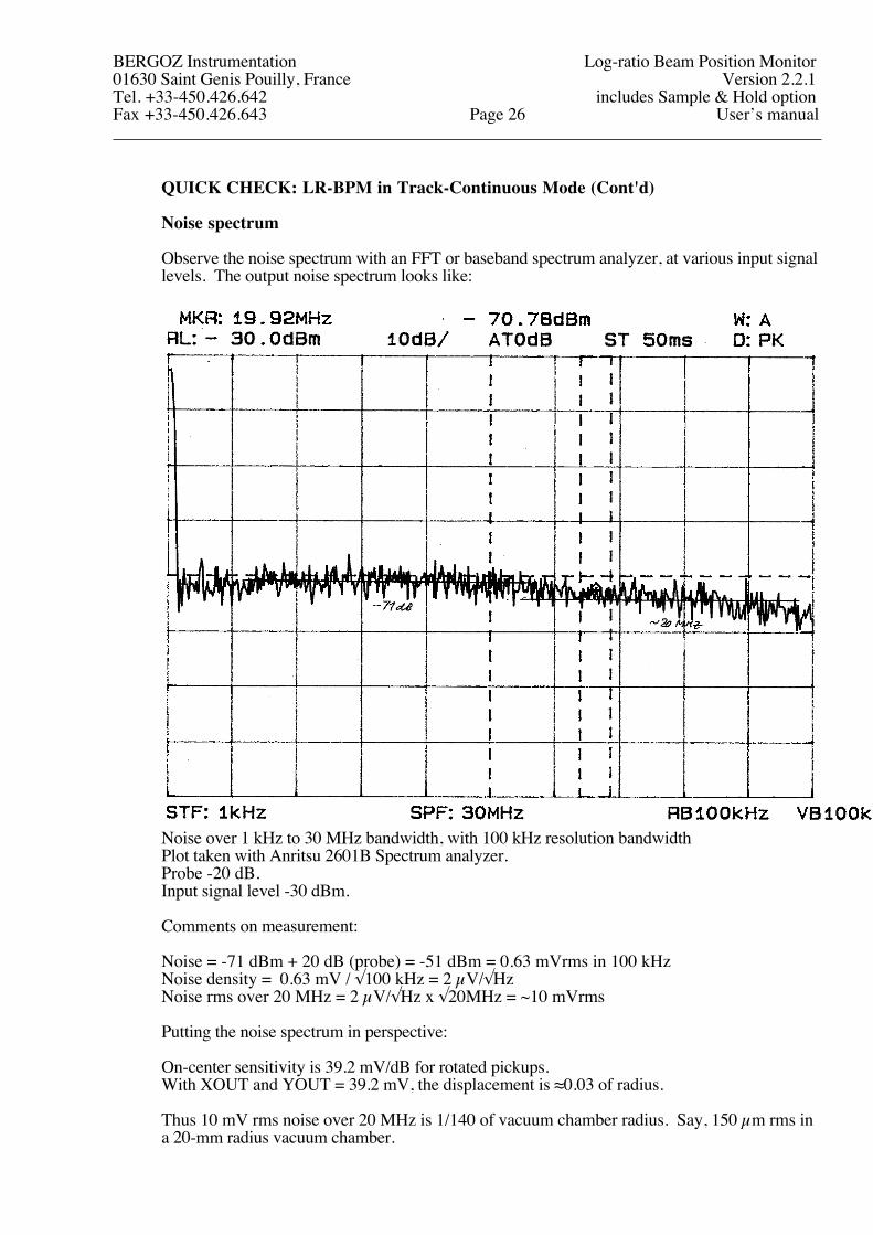
Noise spectrum
Observe the noise spectrum with an FFT or baseband spectrum analyzer, at various input signal levels. The output noise spectrum looks like:
Noise over 1 kHz to 30 MHz bandwidth, with 100 kHz resolution bandwidthPlot taken with Anritsu 2601B Spectrum analyzer.Probe -20 dB.Input signal level -30 dBm.
Comments on measurement:
Noise = -71 dBm + 20 dB (probe) = -51 dBm = 0.63 mVrms in 100 kHzNoise density = 0.63 mV / √100 kHz = 2 µV/√HzNoise rms over 20 MHz = 2 µV/√Hz x √20MHz = ~10 mVrms
Putting the noise spectrum in perspective:
On-center sensitivity is 39.2 mV/dB for rotated pickups.With XOUT and YOUT = 39.2 mV, the displacement is ≈0.03 of radius.
Thus 10 mV rms noise over 20 MHz is 1/140 of vacuum chamber radius. Say, 150 µm rms in a 20-mm radius vacuum chamber.
BERGOZ Instrumentation Log-ratio Beam Position Monitor01630 Saint Genis Pouilly, France Version 2.2.1Tel. +33-450.426.642 includes Sample & Hold optionFax +33-450.426.643 Page 26 User’s manual
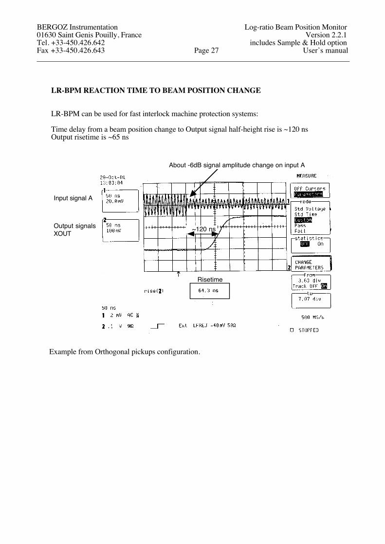
LR-BPM REACTION TIME TO BEAM POSITION CHANGE
LR-BPM can be used for fast interlock machine protection systems:
Time delay from a beam position change to Output signal half-height rise is ~120 nsOutput risetime is ~65 ns
Input signal A
Output signalsXOUT ~120 ns
Risetime
About -6dB signal amplitude change on input A
Example from Orthogonal pickups configuration.
BERGOZ Instrumentation Log-ratio Beam Position Monitor01630 Saint Genis Pouilly, France Version 2.2.1Tel. +33-450.426.642 includes Sample & Hold optionFax +33-450.426.643 Page 27 User’s manual
QUICK CHECK: Beam-Based Center determination
Your shipment may include the product BPM-BBC, BPM Beam-Based Center determination device.
Each BPM-BBC consists of TWO boards. Each one looks like this:
Input 1
Input 2
Output 1
Output 2
Test input 1
Test input 2
Secondary output 1
Secondary output 2
BPM-BBC
Each board handles the signals from two OPPOSITE pickups.E.g. Pickups A & C, or pickups B & D, Up and Down, Left and Right.
Note: BPM-BBC has an insertion loss of 10 dB in each channel.BPM-BBC will not fulfill its purpose of equalizing signals if connected to adjacent pickups. It must be connected to opposite pickups.
Connect the BPM-BBC:
RF SourceA
B
C
D
Powersplitter
BPM-BBC
BPM-BBC
Attenuators
All four unused SMA connectors (Secondary Outputs & Test Inputs) should be terminated by 50Ω.
Connect the A, B, C and D signals to the BPM test kit or 19” BPM-RFC chassis, whichever you use.
Observe the effect of BPM-BBC on X and Y output signals. The pickup inputs must be unequal, so X and Y have non-zero values. Use asymmetrical configuration of attenuators to simulate off-center beam.
BERGOZ Instrumentation Log-ratio Beam Position Monitor01630 Saint Genis Pouilly, France Version 2.2.1Tel. +33-450.426.642 includes Sample & Hold optionFax +33-450.426.643 Page 28 User’s manual
QUICK CHECK Beam-Based Center determination (Cont’d)
BPM-BBC can be enabled by the LR-BPM module, via the pickup coaxial cables.To enable BPM-BBC, the signal BBC.ENABLE/ON must be pulled down.
Enabling BPM-BBC will equalize the signals sent to LR-BPM, simulating beam-on-center.If you use BPM-KIT, pull down BBC.ENABLE by switching ON the DIP switch marked AGCD/BBC.ENABLENote: On BPM-KITs originally made for multiplexed BPMs, this switch is only marked “AGCD”.
LR-BPMBeam Position Monitor
AC mains
ABCD
8-bit DIP switch
Powersupply
BBC.ENABLE.AUX: DB9 pin 8Ground: DB9 pin 4
If you use a 19” BPM-RFC chassis, to enable BPM-BBC you have the alternative:
a) Pull down to ground BBC.ENABLE.AUX on pin 8 of DB9 front panel connector ofLR-BPM moduleNote: Ground is on DB9 pin 4.
b) Pull down BBC.ENABLE on pin 1 of the DB15 chassis rear panel connector which corresponds to the station you are using (refer to picture hereafter).Note: Ground is on DB15 pin 10.
DB9 male External commands input connector. Common to all stations, For use by MX-BPM only
SMA jack RF input for test station
IEC male connector for AC mains
DB15 female BPM station output connector, one per BPM station
SMA jack A to D button inputs, 4 per BPM station, A on top
BERGOZ Instrumentation Log-ratio Beam Position Monitor01630 Saint Genis Pouilly, France Version 2.2.1Tel. +33-450.426.642 includes Sample & Hold optionFax +33-450.426.643 Page 29 User’s manual
LR-BPM PRINCIPLE OF OPERATION
The signals from the pickup electrodes are processed simultaneously thru four independent channels. Each channel consists of an input band-pass filter, followed by an amplification chain with logarithmic response.When a single short pulse is applied to the band-pass filter, it will oscillate at its own resonant frequency for about 250 ns, allowing enough time for the logarithmic amplifier to detect the log of its envelope.
Each amplifying chain produces a signal which peak amplitude is proportional to the log of the input signal, be it a single pulse, a pulse train, or a continuous wave.
Log signals from opposite pickup electrodes are deducted from one another to obtainLog(A) - Log(C) = Log(A/C) which is said to be a very faithful representation of beam displacement between two pickup electrodes.
If the pickup electrodes are placed along the axes in which the beam displacement is to be measured, the displacement X = Kx Log(A/C), directly. The Kx gain is obtained by an amplifier with adjustable gain. The same goes for the Y axis.
If the pickup electrodes are placed along axes rotated as compared to the beam position measurement axes, the A-C and B-D axes must be rotated to obtain the beam displacement values along X and Y. The rotation is done wideband with >5 MHz response applying the algorithm hereafter:
Schematic representation of the log-ratio BPM, an original concept of Robert E. Shafer:Y
[mm] Y [V] = ky log A/B =ky (log A - log B) ≈
≈ ky r+-
r
log
log
A
B
Position measured by this method is more linear, over a wider range, than difference-over-sum.
BLOCK DIAGRAM
X
Y
logA logALPF BPF
+-C logC
LPF BPF
logB logBLPF BPF
+-
logD logDLPF BPF
Buf
Buf
Buf
Buf
LogA-logC
LogB-logD
Axesrotation
(if pickupsare rotated)
logSum of logs
BERGOZ Instrumentation Log-ratio Beam Position Monitor01630 Saint Genis Pouilly, France Version 2.2.1Tel. +33-450.426.642 includes Sample & Hold optionFax +33-450.426.643 Page 30 User’s manual
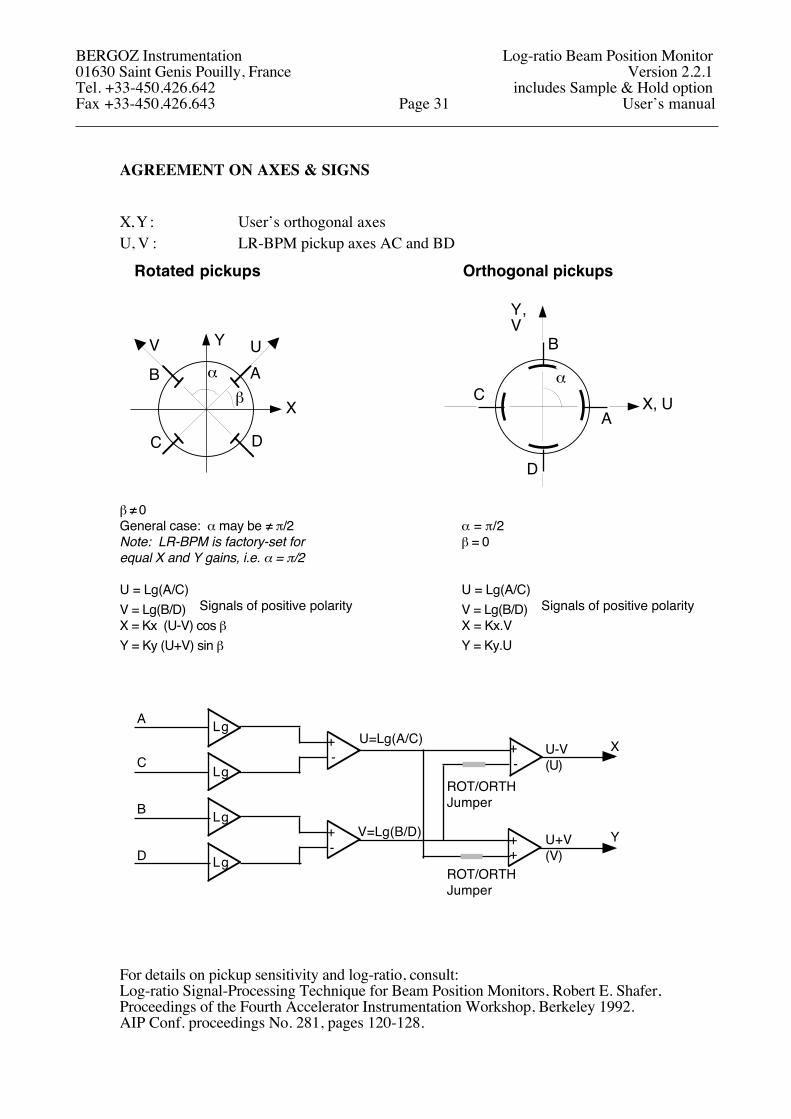
AGREEMENT ON AXES & SIGNS
X, Y : User’s orthogonal axesU, V : LR-BPM pickup axes AC and BD
Rotated pickups Orthogonal pickups
Y
X
AB
C D
α
V U B
C
D
AX, U
Y,V
αβ
β ≠ 0General case: α may be ≠ π/2 α = π/2Note: LR-BPM is factory-set for β = 0equal X and Y gains, i.e. α = π/2
U = Lg(A/C) U = Lg(A/C)V = Lg(B/D) Signals of positive polarity V = Lg(B/D) Signals of positive polarityX = Kx (U-V) cos β X = Kx.VY = Ky (U+V) sin β Y = Ky.U
++
XLgA
C
LgB+-
LgD
U=Lg(A/C)
V=Lg(B/D)
Lg
+- +
-
Y
ROT/ORTHJumper
ROT/ORTHJumper
U-V(U)
U+V(V)
For details on pickup sensitivity and log-ratio, consult:Log-ratio Signal-Processing Technique for Beam Position Monitors, Robert E. Shafer, Proceedings of the Fourth Accelerator Instrumentation Workshop, Berkeley 1992.AIP Conf. proceedings No. 281, pages 120-128.
BERGOZ Instrumentation Log-ratio Beam Position Monitor01630 Saint Genis Pouilly, France Version 2.2.1Tel. +33-450.426.642 includes Sample & Hold optionFax +33-450.426.643 Page 31 User’s manual
BPM-BBC PRINCIPLE OF OPERATION
The BPM-BBC circuit brings the user the possibility to measure the BPM X and Y zero offsets immediately, with beam, at the actual intensity of the beam.
When Short bunch pulses are applied to the BPM-BBC two inputs, couplers produce two single sine wave signals on its outputs. The sine wave period is independent on bunch length.The amplitude of the two output waves are equal if the bunch is on center.If the bunch is off-center, the amplitudes are different.
When BPM-BBC is enabled, the PIN-diode is conductive. It unites the two outputs, equalizing their sine wave amplitudes if they were different. This simulates the conditions of a beam on center. Therefore, when the BPM-BBC is enabled, any non-zero X or Y output value given by LR-BPM is a zero offset. These offsets are caused the LR-BPM electronics, and by unequal attenuation of the BBC–to–LR-BPM cables.
To enable BPM-BBC, a TTL signal BBC.ENABLE must be applied to the LR-BPM module.It causes the PIN-diode to be biased, making it conductive.
A
C
A
C
To BPM module
LR-BPM
+15V
BBC.ENABLE
BBC.ENABLE
BPM-BBC
-15V
+15V-15V
Insertion loss: 10 dB per channel
The beam signals applied to BPM-BBC should be synchronous, otherwise the level of equalized signals diminishes.. Thus, it is recommended to connect the BPM-BBCs to the pickups with short cables of equal length.
BERGOZ Instrumentation Log-ratio Beam Position Monitor01630 Saint Genis Pouilly, France Version 2.2.1Tel. +33-450.426.642 includes Sample & Hold optionFax +33-450.426.643 Page 32 User’s manual
SIGNALS
Input signals
BUTA Pickup inputs A, B, C, and D. Impedance 50Ω. BUTB See Agreement on Axes & Signs, BUTC this manual, for pickup assignments.BUTD
Output signals for ADC
XOUT X displacement. Bipolar signal up to ±2V(0 Volt represents pickup center)Output impedance: 100 Ω
YOUT Y displacement. Bipolar signal up to ±2V(0 Volt represents pickup center)Output impedance: 100 Ω
VPHOUT Phase angle output ±9V = ±90° RF to Phase reference angle(LR-BPM with BPPM option only)
Auxiliary Output Signals
XOUT.AUX Same as XOUT, but 50-Ω output impedance
YOUT.AUX Same as YOUT, but 50-Ω output impedance
XYGND Analog ground for XOUT.AUX and YOUT.AUX
BERGOZ Instrumentation Log-ratio Beam Position Monitor01630 Saint Genis Pouilly, France Version 2.2.1Tel. +33-450.426.642 includes Sample & Hold optionFax +33-450.426.643 Page 33 User’s manual
SIGNALS (Cont’d)
External Trigger Input and Trigger Gate
TRG.IN.AUX Input for external trigger50 Ω, positive edge > 2 V
TRG.GATE Input for gating the beam triggerTTL, High-Low-HighHigh state inhibits Built-in Beam TriggerLow state (default state) allows Built-in Beam Trigger.
SUM&TRG.GND Ground for TRG.IN.AUX -and- TRG.GATE.
Optional Output Wideband SignalsNote: These optional output signals are made available to compute beam position when the algorithm implemented in the LR-BPM circuit, i.e. Log(A/C) is unsuitable. This can be the case of 6-button BPM pickups, or asymmetric geometry of pickup electrodes.
LOGA Logarithmic representation of BUTA input. LOGB Logarithmic representation of BUTB input. LOGC Logarithmic representation of BUTC input. LOGD Logarithmic representation of BUTD input.
External Controls
BBC.ENABLE BPM-BBC Beam-Based Center determination Enable signalTTL signal. Pull down to equalize BBC output signals. Pullup resistor 4K7 to 5V.
TRACK.CONTINUOUSTTL signal. To set Track-Continuous mode.High state (default) sets Track&Hold mode.Pull down for Track-Continuous mode. Pullup resistor 4K7 to 5V.
GND Ground for above signals.
Common external commandsCommon external commands are commands which are common to all BPM modules in a BPM chassis.
None are handled by LR-BPM
BERGOZ Instrumentation Log-ratio Beam Position Monitor01630 Saint Genis Pouilly, France Version 2.2.1Tel. +33-450.426.642 includes Sample & Hold optionFax +33-450.426.643 Page 34 User’s manual
CONNECTORS PINS ALLOCATION Rev. 2.1
DB15 female connector on BPM-RFC rear panel (one connector per BPM station)DB15 female connector on BPM-RFC rear panel (one connector per BPM station)DB15 female connector on BPM-RFC rear panel (one connector per BPM station)DB15 female connector on BPM-RFC rear panel (one connector per BPM station)DB15 female connector on BPM-RFC rear panel (one connector per BPM station)
DIN41612M LR-BPM module rear connector
DB9 female connector on LR-BPM front panelDB9 female connector on LR-BPM front panel
Input signalsInput A BUTA b2 *Input B BUTB b5 *Input C BUTC b8 *Input D BUTD b11*Phase reference (BPPM option only) PHREF b22* * Coaxial insert 1.0/2.3 type
Power supply+ (8...15) V +15V c13- (8...15) V -15V c15Common COM c14
BERGOZ Instrumentation Log-ratio Beam Position Monitor01630 Saint Genis Pouilly, France Version 2.2.1Tel. +33-450.426.642 includes Sample & Hold optionFax +33-450.426.643 Page 35 User’s manual
BPM CABLES LAYOUT INSTALLATION
Cable layout
Cables electrical length must be equal within ±1ns. Yet, unlike most BPM electronics, the LR-BPM module does not require the input signals to be in phase. It tolerates any phase change, even 180°.
Unnecessary intermediate connectors should be avoided. When –for practical reasons– patch-panels must be used, the cables on either side of the patch-panel should be passed through tubular ferrite cores. Ferrite material must have high permeability at the BPM operating frequency.
The four cables pertaining to the same BPM stations must be laid side by side. Cables, BPM chassis and modules should be kept away –as much as possible– from RF equipment, klystrons, cavities.
Connectors must be chosen carefully to match the cable used. Connectors manufacturers instructions must be followed meticulously. If cable layout is subcontracted, subcontractors must be informed of the extreme reliability expected from these cables. All cables with connectors must be checked before installation with a network analyzer, up to twice the operating frequency at least; i.e. up to 1 GHz for 500 MHz operating frequency.
BPM modules must be installed in an RF-shielded chassis.
BERGOZ Instrumentation Log-ratio Beam Position Monitor01630 Saint Genis Pouilly, France Version 2.2.1Tel. +33-450.426.642 includes Sample & Hold optionFax +33-450.426.643 Page 36 User’s manual
ACCESSORIES
Table-top test kit (BPM-KIT)
The table-top test kit “BPM-KIT” is an accessory which can be used to test the following modules made by Bergoz Instruments:• MX-BPM multiplexed BPM, earlier called simply “BPM”.• VF-BPM multiplexed BPM for variable frequency (ramped) accelerators• LR-BPM log-ratio BPM.
BPM-KIT currently delivered are all equipped with a universal mains voltage power supply. Yet, older units have been delivered to users with 100 Vac, 115 Vac and 220/230 Vac mains voltage. Check AC mains voltage on power supply module before using.
The BPM-KIT includes:
• A power supply. • A DIN41612M 24+8 mating connector• Four coaxial cables connected to the button inputs, terminated by SMA plugs• A DB9 male connector for External Commands input.
Similar connector and pin-out as used on the BPM chassis BPM-RFC/X• A DB15 female connector for Output signals
Similar connector and pin-out as used on the BPM chassis BPM-RFC/X• Five BNC jacks to view signals like XOUT and YOUT.
The BPM-KIT is very convenient. It allows the BPM module to be placed flat on the table.In this position, the shield can be removed, and the user has access to all switches, Jumpers, filters and potentiometers.
Card Extender BPM-XTD
The card extender allows access to the BPM module adjustments while it is connected to the chassis, thus to the readout and control system.
The BPM-XTD is not as convenient as the BPM-KIT for adjustments.
The coaxial connections extensions of the button signals cause an offset of the X and Y outputs when the extender is used. This is due to the difference in signal attenuation between the 4 extension cables. These differences are recorded on a label affixed to the extender.
BERGOZ Instrumentation Log-ratio Beam Position Monitor01630 Saint Genis Pouilly, France Version 2.2.1Tel. +33-450.426.642 includes Sample & Hold optionFax +33-450.426.643 Page 37 User’s manual
ACCESSORIES (Cont’d)
TTL Commands Service module BPM-SERV/CMD
The TTL Commands Service module can be inserted in a BPM station of a chassis, in place of the BPM module.
It brings to the front panel:
• On a DB9 female connector, the External Commands applied by the control system to this station.Similar connector pin-out as used on BPM-RFC/X and BPM-KIT, but reversed gender.
• On a DB15 male connector, the Output lines to which the BPM module would apply its Outputs.Similar connector pin-out as used on BPM-RFC/X and BPM-KIT, but reversed gender.
This module is useful because access to the cables at the rear of the chassis can be very difficult.With this module, one can:
(a) Observe and debug the signals sent by the control system to a BPM station(b) Feed known signals into the BPM readout system, to test it.
RF Service module BPM-SERV/RF
The RF Service module can be inserted in a BPM station of a chassis, in place of the BPM module.
It brings to the front panel –on SMA jacks– the four signals applied to this BPM station by the BPM buttons.
For oscilloscope and spectrum analyzer viewing of the BPM button signals.
Very useful, because the RF cables at the rear of the chassis are too crowded to be disconnected.
BERGOZ Instrumentation Log-ratio Beam Position Monitor01630 Saint Genis Pouilly, France Version 2.2.1Tel. +33-450.426.642 includes Sample & Hold optionFax +33-450.426.643 Page 38 User’s manual
ACCESSORIES (Cont’d)
BPM Chassis BPM-RFC/XThe BPM-RFC/X chassis is built around a 19” Schroff rackable RF chassis.Dimensions of the bin: 3U x 84FSchroff reference: Europac Lab HF/RF #20845-283
The BPM-RFC/X is available equipped for 1 up to 16 BPM stations. X being the number of stations.
BPM-RFC/X with less than 16 stations are partially equipped BPM-RFC/16. As a result, allBPM chassis are field-upgradable to the full 16-station chassis.
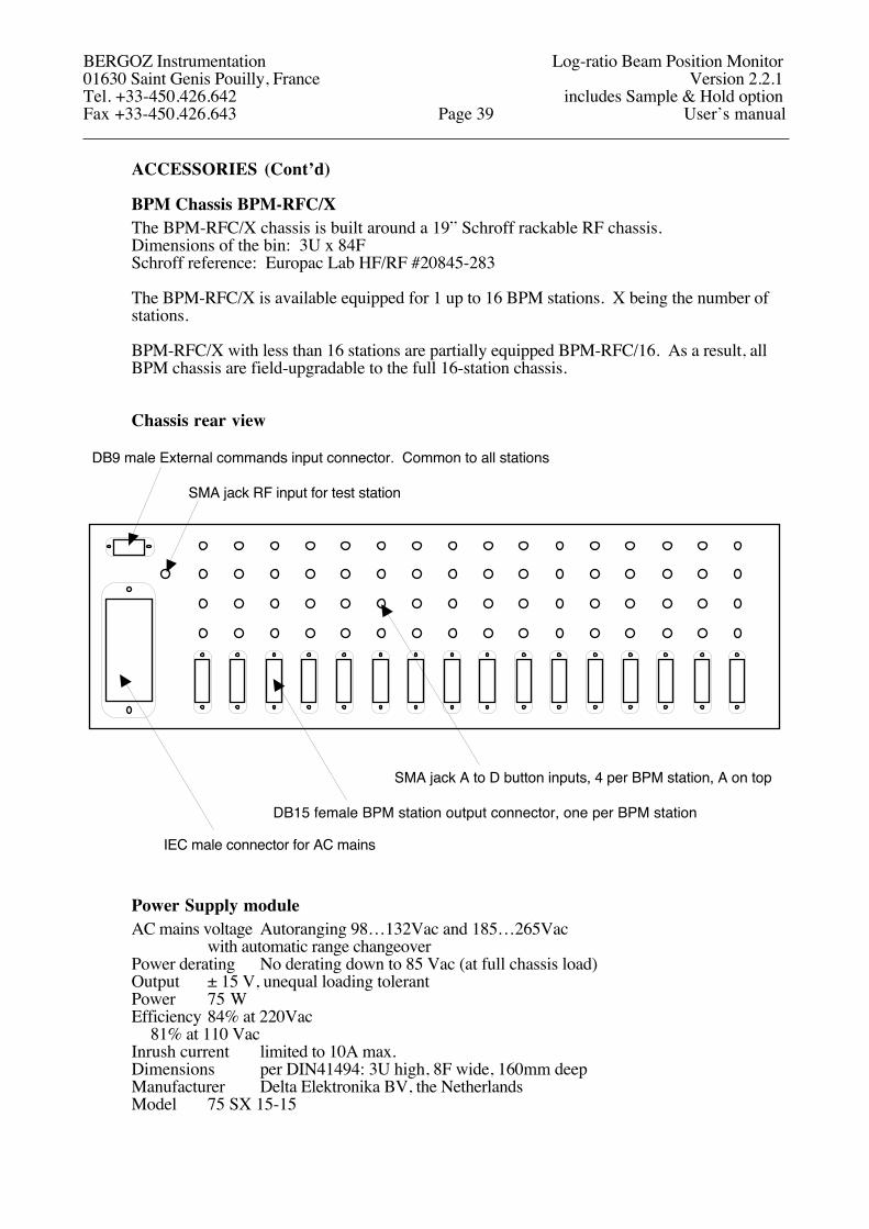
Chassis rear view
DB9 male External commands input connector. Common to all stations
SMA jack RF input for test station
IEC male connector for AC mains
DB15 female BPM station output connector, one per BPM station
SMA jack A to D button inputs, 4 per BPM station, A on top
Power Supply moduleAC mains voltage Autoranging 98…132Vac and 185…265Vac
with automatic range changeoverPower derating No derating down to 85 Vac (at full chassis load)Output ± 15 V, unequal loading tolerantPower 75 WEfficiency 84% at 220Vac
81% at 110 VacInrush current limited to 10A max.Dimensions per DIN41494: 3U high, 8F wide, 160mm deepManufacturer Delta Elektronika BV, the NetherlandsModel 75 SX 15-15
BERGOZ Instrumentation Log-ratio Beam Position Monitor01630 Saint Genis Pouilly, France Version 2.2.1Tel. +33-450.426.642 includes Sample & Hold optionFax +33-450.426.643 Page 39 User’s manual
ACCESSORIES (Cont’d)
BPM Chassis BPM-RFC/X Outer dimensions
37,5
57,1
37,5465,1483,0
10,4
7,5
302,2
Leave clearance for connectors and cables
132,5
441 + lateral screw heads (~6mm)
Warning:Leave clearance at top and bottomto allow free air flow for convection cooling.Allow 10W max. heat dissipation per module installed in chassis.
Front view
Top view
Rear view
BERGOZ Instrumentation Log-ratio Beam Position Monitor01630 Saint Genis Pouilly, France Version 2.2.1Tel. +33-450.426.642 includes Sample & Hold optionFax +33-450.426.643 Page 40 User’s manual
BPM MODULE REAR CONNECTOR DIN41612M 24+8
Note: For connections, See Connector Pins Allocation, this manual.
BPM chassis for 1 up to 16 BPM modules are part of Bergoz Instrumentation sales program (BPM-RFC/X) and include the necessary mating connectors (See BPM chassis, this manual). The following is of interest to those who wish to design their own chassis.
The BPM module rear connector commonly designated DIN41612M 24+8 is a male connector with 24 pin contacts and 8 holes for coaxial connectors. V42254-B1200-M240 from Siemens is the reference used.
The coaxial connectors inserted in the rear connector are of the “jack”-type series 1.0/2.3.Four V23601-A1227-E1 from Siemens are used for button inputs (jack, right angle, soldering type)One V23601-A602-E71 from Siemens is used for the optional Fast Gate (jack, straight, crimp)
On the chassis side (or “Backplane” side), for each BPM module, the following is needed:
• One DIN41612M female connector with 24 pin contacts and 8 holes for coaxial connectors.We recommend using Siemens connectors to assure compatibility:V42254-B2240-M240 from Siemens, for wrapping connectionV42254-B2202-M240 from Siemens, for soldering connection (4.5-mm pins)Other references available for press-fit connection.
• Four or five coaxial “plug”-type connectors, series 1.0/2.3.A large number of manufacturers produce these connectors. However, to assure good connector mating, we recommend that you use connectors from Siemens:V23601-B302-E71 or V23601-A302-E71 for straight cable attachment to RG316 (Øext.≤2.6mm)V23601-A302-E1 for straight cable attachment to RG178 (Øext.≤1.9mm)V23601-A502-E71 (18.7mm long) for 90° angle cable attachment.to RG316 (Øext.≤2.6mm)V23601-A556-E71 (22.3mm long) for 90° angle cable attachment.to RG316 (Øext.≤2.6mm)V23601-A502-E73 (18.7mm long) for 90° angle cable attachment.to RD316 (Øext.≤3.0mm)V23601-A556-E73 (22.3mm long) for 90° angle cable attachment.to RD316 (Øext.≤3.0mm)
Siemens recommends to use connector crimping tool reference M1002-K1.
Note: At printing time, the connectors division of Siemens has been purchased by Tyco Electronics. Tyco Electronics intends to change the ex-Siemens part numbers, but will maintain a parts number cross reference, for an unspecified length of time.
BERGOZ Instrumentation Log-ratio Beam Position Monitor01630 Saint Genis Pouilly, France Version 2.2.1Tel. +33-450.426.642 includes Sample & Hold optionFax +33-450.426.643 Page 41 User’s manual
SCHEMATICS & BOARD LAYOUT
Schematics and board layouts of our instruments remain the exclusive property of Bergoz Instrumentation at all times. They are protected by the copyright laws.
Schematics and board layouts are not delivered with our instruments. They can be obtained at the specific request of the instrument’s user.
A request should be sent by fax, worded in the following way:
To: Bergoz InstrumentationFrom: *User's name*Date:................I am a user of instrument type xxx-xxx serial nr. xxx,xxx,xxx,xxx, etc.Please send me one copy of the corresponding schematics and board layout.I will use it for the instrument’s maintenance only.I will make copies only for my own use.I will inform others who need these schematics that they should request them from Bergoz Instrumentation.Signed: .......................
ACKNOWLEDGEMENT
The fundamental principles of our Log-ratio BPM module were developed by Robert E. Shafer while at Los Alamos National Laboratory. We sincerely thank him for his considerable contribution.
Our LR-BPM module was developed by Alexandre Kalinine. Earlier work was performed by Klaus Unser and Jim Hinkson, which contributed to Kalinine’s design.
Saint Genis Pouilly, December 2001Last revised April 2008
BERGOZ Instrumentation Log-ratio Beam Position Monitor01630 Saint Genis Pouilly, France Version 2.2.1Tel. +33-450.426.642 includes Sample & Hold optionFax +33-450.426.643 Page 42 User’s manual