431-HDBK-000076 Revision - Effective Date: To be Added Upon Release Expiration Date: To be Added Upon Release CHECK WITH RLEP DATABASE AT: https://lunarngin.gsfc.nasa.gov TO VERIFY THAT THIS IS THE CORRECT VERSION PRIOR TO USE. Robotic Lunar Exploration Program Lunar Reconnaissance Orbiter Mission Telemetry & Command (T&C) Database (DB) Style Guide 02/03/2006 Goddard Space Flight Center Greenbelt, Maryland National Aeronautics and Space Administration DRAFT
Transcript
431-HDBK-000076Revision -
Effective Date: To be Added Upon ReleaseExpiration Date: To be Added Upon Release
CHhttp
TO VERIFY THAT THI
Robotic Lu
Lunar Reco
Telemetry & Co
G
National Aeronautics andSpace Administration
T
DRAF
ECK WITH RLEP DATABASE AT:s://lunarngin.gsfc.nasa.govS IS THE CORRECT VERSION PRIOR TO USE.
This document is a Lunar Reconnaissance Orbiter (LRO) Project ConfigurationManagement (CM)-controlled document. Changes to this document require priorapproval of the applicable Configuration Control Board (CCB) Chairperson or designee.Proposed changes shall be submitted to the LRO CM Office (CMO), along withsupportive material justifying the proposed change. Changes to this document will bemade by complete revision.
Questions or proposed changes concerning this document shall be addressed to:
1.0 INTRODUCTIONThe Lunar Reconnaissance Orbiter (LRO) is the first robotic mission of the RoboticLunar Exploration Program (RLEP). The primary objective of the LRO mission is toconduct investigations that support future human exploration of the Moon. The launchreadiness date for LRO is October 2008.
1.1. PURPOSE AND SCOPEThe LRO Project has multiple teams contributing database inputs in order to generate afully integrated database for use by the Integrated Test and Operations System (ITOS)ground system. Therefore, it is necessary to define a common format and namingconvention to avoid conflicting inputs and to ensure usability. This document containsguidelines for naming command mnemonics, telemetry mnemonics, discrete names,analog conversion definitions, limit definitions, and database filenames as well as theoverall format of the files and individual record types.
All teams contributing database inputs to the LRO ITOS ground system shall followthese guidelines.
1.2. DOCUMENT STRUCTUREThe following describes the document breakdown structure:
Section 1: Introduction – This section describes the purpose and scope of the databasestyle document.
Section 2: Observatory Overview – This section provides a high-level overview of theLRO spacecraft (SC) and instruments.
Section 3: ITOS Database Style Guidelines – This section describes the elementsrequired for the ITOS database. Guidelines are provided for the format of the databasefiles and records as well as the conventions for naming mnemonics and files.
1.3. APPLICABLE DOCUMENTSThe following list contains the reference material used to generate this document. Referto these sources to support, further define, and clarify the information in this document.
431-OPS-000042 Lunar Reconnaissance Orbiter Launch and CommissioningHandbook
http://itos.gsfc.nasa.gov/ Integrated Test and Operations System (ITOS) website
2.0 MISSION OVERVIEWLRO is the first mission of the RLEP. The goal for the RLEP is to prepare for futurehuman exploration of the Moon. LRO specific objectives are:
Characterize the lunar radiation environment, biological impacts, and potentialmitigation
Determine a high resolution global, geodetic grid of the Moon in 3 dimensions Assess in detail the resources and environments of the Moon’s polar cap regions Perform high spatial resolution measurement of the Moon’s surface
The LRO instrument complement includes six instruments. Together, all six instrumentsallow LRO to meet the mission objectives.
LRO will also fly a technology demonstration instrument called the Mini-RadioFrequency (RF). The purpose of the Mini-RF is to demonstrate new radar technologyfor future use in planetary resource mapping. The Mini-RF payload will operate on anon-interference basis throughout the mission.
As of the creation of this document, the major spacecraft and subsystem functions are:
Command and Data Handling (C&DH)─ Provides SC processor for attitude control algorithms, command/telemetry
processing.─ Communication cards provide the interfaces to the S-band/Ka-Band RF
systems.─ Hardware command decoding for computer-free recovery─ Provides high speed and low speed data bus to the instruments and SC
components─ Provides large volume recorder for measurement data and orbiter
housekeeping (HK) Guidance Navigation and Control (GN&C)─ Three axis control with reaction wheels─ Star Trackers (STs), Inertial Measurement Unit (IMU), Coarse Sun Sensors
(CSS) used for attitude control─ Momentum management is performed periodically with thrusters─ Control pointing of the solar array (SA) and High Gain Antenna (HGA)
gimbals Communication─ Ka-band transmitter for high rate measurement downlink using the HGA─ S-Band transponders connected to the omni antennas and HGA for receipt of
ground commands and telemetry downlink─ Orbit determination via turnaround ranging
Power─ SA located on gimbals for power generation─ One Lithium Ion battery for launch and 48 minute lunar occultations─ Power switching and distribution─ Battery charging control
Flight Software (FSW)─ Complex algorithms computed on central processor including Attitude Control
System (ACS), stored commanding, telemetry and measurement dataprocessing, and fault detection and correction.
─ SC time distribution/maintenance
The six instruments are:
Lunar Orbiter Laser Altimeter (LOLA): LOLA will determine the globaltopography of the lunar surface at high resolution, measuring landing site slopesand search for polar ice in shadow regions.
Lunar Reconnaissance Orbiter Camera (LROC): LROC will acquire targetedimages of the lunar surface capable of resolving small-scale features that couldbe landing site hazards. LROC will also produce wide-angle images at multiplewavelengths of the lunar poles to document the changing illumination conditionsand potential resources.
Lunar Exploration Neutron Detector (LEND): LEND will map the flux ofneutrons from the lunar surface to search for evidence of water ice and providemeasurements of space radiation environment which can be useful for futurehuman exploration.
Diviner Lunar Radiometer Experiment (DLRE): Diviner will map thetemperature of the entire lunar surface at 300-meter horizontal scales to identifycold-traps and potential ice deposits.
Lyman-Alpha Mapping Project (LAMP): LAMP will observe the entire lunarsurface in the far ultraviolet (UV). LAMP will search for surface ice and frost inthe Polar Regions and provide images of permanently shadowed regionsilluminated only by starlight.
Cosmic Ray Telescope for Effects of Radiation (CRaTER): CRaTER willinvestigate the effect of galactic cosmic rays on tissue-equivalent plastics as aconstraint on models of biological response to background space radiation.
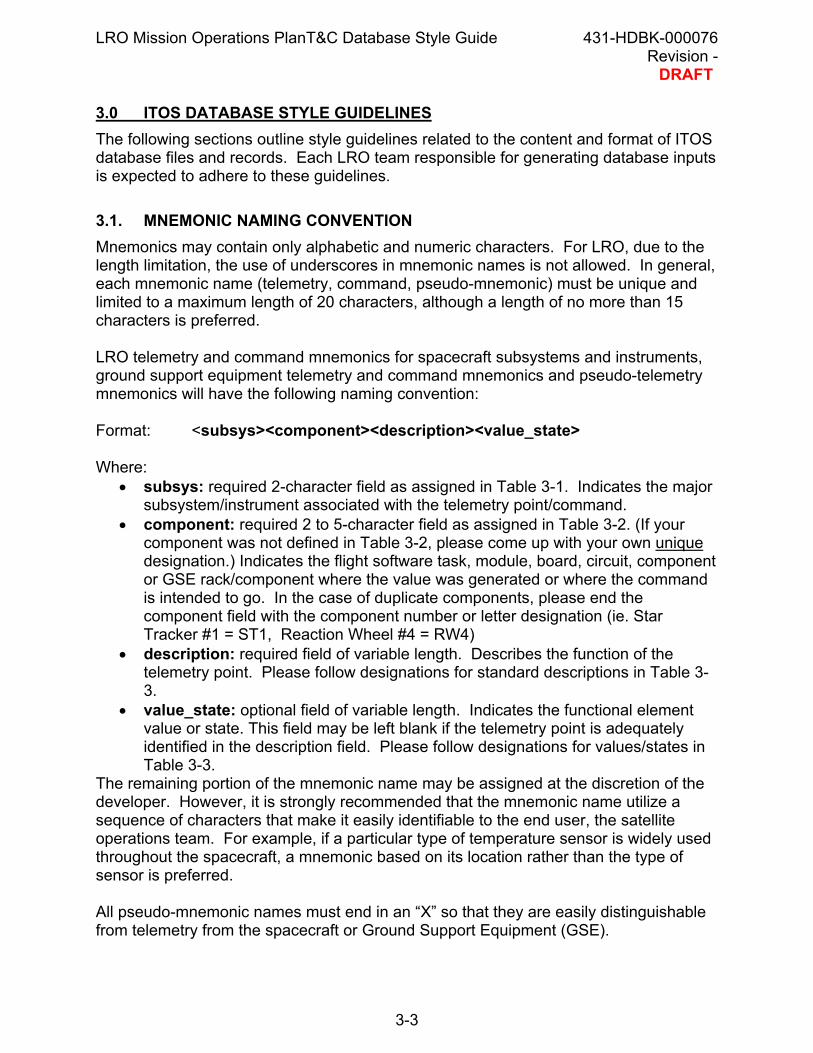
3.0 ITOS DATABASE STYLE GUIDELINESThe following sections outline style guidelines related to the content and format of ITOSdatabase files and records. Each LRO team responsible for generating database inputsis expected to adhere to these guidelines.
3.1. MNEMONIC NAMING CONVENTIONMnemonics may contain only alphabetic and numeric characters. For LRO, due to thelength limitation, the use of underscores in mnemonic names is not allowed. In general,each mnemonic name (telemetry, command, pseudo-mnemonic) must be unique andlimited to a maximum length of 20 characters, although a length of no more than 15characters is preferred.
LRO telemetry and command mnemonics for spacecraft subsystems and instruments,ground support equipment telemetry and command mnemonics and pseudo-telemetrymnemonics will have the following naming convention:
Where:• subsys: required 2-character field as assigned in Table 3-1. Indicates the major
subsystem/instrument associated with the telemetry point/command.• component: required 2 to 5-character field as assigned in Table 3-2. (If your
component was not defined in Table 3-2, please come up with your own uniquedesignation.) Indicates the flight software task, module, board, circuit, componentor GSE rack/component where the value was generated or where the commandis intended to go. In the case of duplicate components, please end thecomponent field with the component number or letter designation (ie. StarTracker #1 = ST1, Reaction Wheel #4 = RW4)
• description: required field of variable length. Describes the function of thetelemetry point. Please follow designations for standard descriptions in Table 3-3.
• value_state: optional field of variable length. Indicates the functional elementvalue or state. This field may be left blank if the telemetry point is adequatelyidentified in the description field. Please follow designations for values/states inTable 3-3.
The remaining portion of the mnemonic name may be assigned at the discretion of thedeveloper. However, it is strongly recommended that the mnemonic name utilize asequence of characters that make it easily identifiable to the end user, the satelliteoperations team. For example, if a particular type of temperature sensor is widely usedthroughout the spacecraft, a mnemonic based on its location rather than the type ofsensor is preferred.
All pseudo-mnemonic names must end in an “X” so that they are easily distinguishablefrom telemetry from the spacecraft or Ground Support Equipment (GSE).
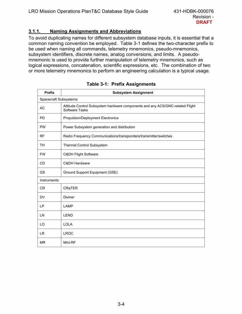
3.1.1. Naming Assignments and AbbreviationsTo avoid duplicating names for different subsystem database inputs, it is essential that acommon naming convention be employed. Table 3-1 defines the two-character prefix tobe used when naming all commands, telemetry mnemonics, pseudo-mnemonics,subsystem identifiers, discrete names, analog conversions, and limits. A pseudo-mnemonic is used to provide further manipulation of telemetry mnemonics, such aslogical expressions, concatenation, scientific expressions, etc. The combination of twoor more telemetry mnemonics to perform an engineering calculation is a typical usage.
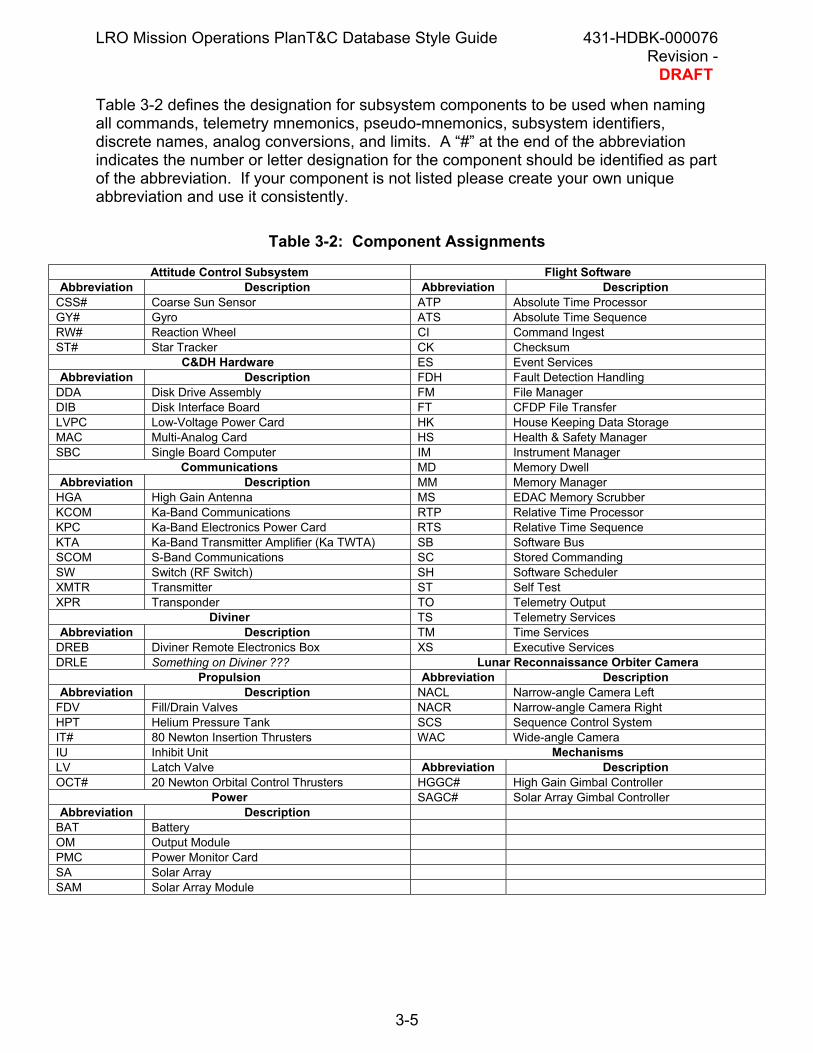
Table 3-2 defines the designation for subsystem components to be used when namingall commands, telemetry mnemonics, pseudo-mnemonics, subsystem identifiers,discrete names, analog conversions, and limits. A “#” at the end of the abbreviationindicates the number or letter designation for the component should be identified as partof the abbreviation. If your component is not listed please create your own uniqueabbreviation and use it consistently.
Table 3-2: Component Assignments
Attitude Control Subsystem Flight SoftwareAbbreviation Description Abbreviation Description
CSS# Coarse Sun Sensor ATP Absolute Time ProcessorGY# Gyro ATS Absolute Time SequenceRW# Reaction Wheel CI Command IngestST# Star Tracker CK Checksum
C&DH Hardware ES Event ServicesAbbreviation Description FDH Fault Detection Handling
DDA Disk Drive Assembly FM File ManagerDIB Disk Interface Board FT CFDP File TransferLVPC Low-Voltage Power Card HK House Keeping Data StorageMAC Multi-Analog Card HS Health & Safety ManagerSBC Single Board Computer IM Instrument Manager
Communications MD Memory DwellAbbreviation Description MM Memory Manager
HGA High Gain Antenna MS EDAC Memory ScrubberKCOM Ka-Band Communications RTP Relative Time ProcessorKPC Ka-Band Electronics Power Card RTS Relative Time SequenceKTA Ka-Band Transmitter Amplifier (Ka TWTA) SB Software BusSCOM S-Band Communications SC Stored CommandingSW Switch (RF Switch) SH Software SchedulerXMTR Transmitter ST Self TestXPR Transponder TO Telemetry Output
Diviner TS Telemetry ServicesAbbreviation Description TM Time Services
DREB Diviner Remote Electronics Box XS Executive ServicesDRLE Something on Diviner ??? Lunar Reconnaissance Orbiter Camera
Propulsion Abbreviation DescriptionAbbreviation Description NACL Narrow-angle Camera Left
FDV Fill/Drain Valves NACR Narrow-angle Camera RightHPT Helium Pressure Tank SCS Sequence Control SystemIT# 80 Newton Insertion Thrusters WAC Wide-angle CameraIU Inhibit Unit MechanismsLV Latch Valve Abbreviation DescriptionOCT# 20 Newton Orbital Control Thrusters HGGC# High Gain Gimbal Controller
Power SAGC# Solar Array Gimbal ControllerAbbreviation Description
BAT BatteryOM Output ModulePMC Power Monitor CardSA Solar ArraySAM Solar Array Module
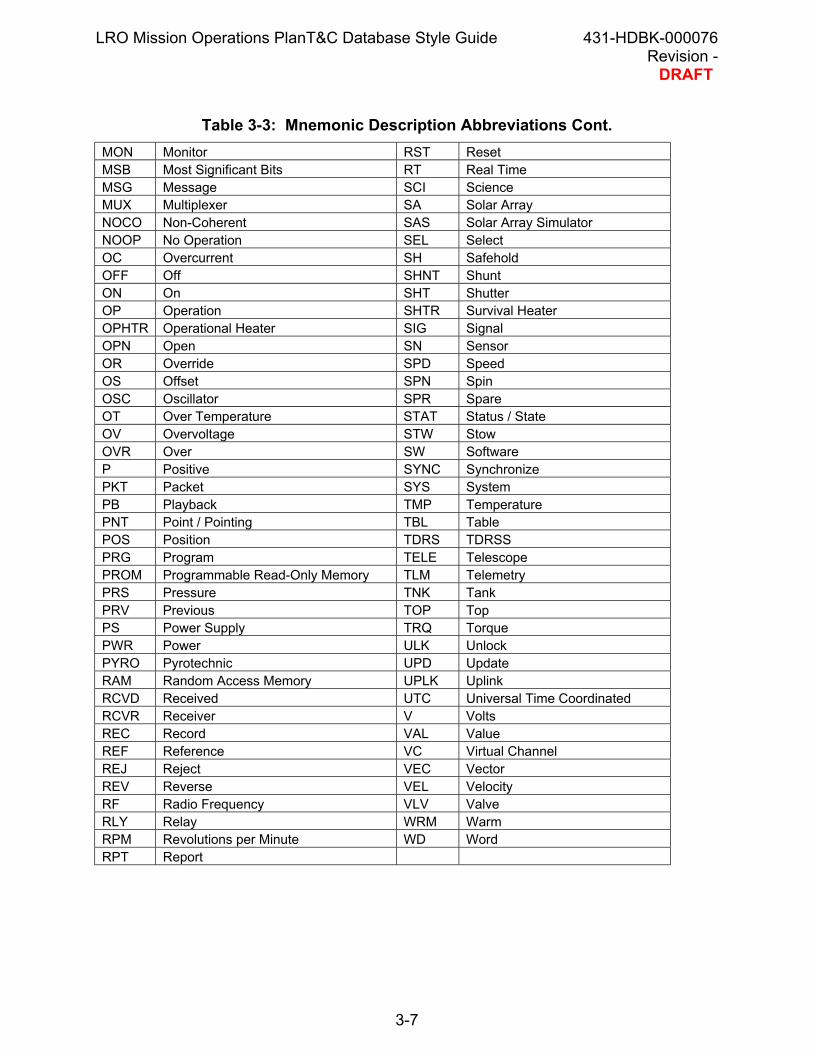
Table 3-3 suggests abbreviations for standard mnemonic descriptions. Please followthese abbreviations when possible. If needed, please create your own uniquedecription and use it consistently.
Table 3-3: Mnemonic Description Abbreviations
Abbr Description Abbr DescriptionADDR Address ENC Encode / EncoderAGC Automatic Gain Control ERR ErrorAMP Amplitude EXE ExecutionANG Angle FEP Front End ProcessorANT Antenna FIRE Fire (pyro)APID CCSDS Application ID FLG FlagARM Arm (pyro) FLT FilterAUX Auxillary FMT FormatBAT Battery FN FineBDY Body FPGA Field Programmable Gate ArrayBOT Bottom FRM FrameBP Baseplate FS Frequency StandardBS Bias FW Filter WheelBUF Buffer FWD ForwardBUS Bus GCE Gimbal Control ElectronicsCAL Calibrate/Calibration GN GainCCD Charge Coupled Device HI HighCFG Configuration HK HousekeepingCHN Channel HTR HeaterCKSM Checksum HW HardwareCLD Cold I CurrentCLS Closed ID IdentificationCLK Clock INIT InitializationCLR Clear INST InstrumentCMD Command INT InternalCNT Count LCK LockCNV Convert/Converter LD LoadCOHO Coherent LIM LimitCTRL Control LN LineDET Detector LO LowDIR Direction LSB Least Significant BitsDIS Disable LVL LevelDLY Delay M MinusDMP Dump MAG MagneticDNLK Downlink MAX MaximumDRV Drive MD ModeDWL Dwell MEM MemoryENG Engineering MF Mainframe / Main FrameEEPR EEPROM MIN MinimumEL Elevation MIRR MirrorENA Enable MOD Modulation
Table 3-3: Mnemonic Description Abbreviations Cont.MON Monitor RST ResetMSB Most Significant Bits RT Real TimeMSG Message SCI ScienceMUX Multiplexer SA Solar ArrayNOCO Non-Coherent SAS Solar Array SimulatorNOOP No Operation SEL SelectOC Overcurrent SH SafeholdOFF Off SHNT ShuntON On SHT ShutterOP Operation SHTR Survival HeaterOPHTR Operational Heater SIG SignalOPN Open SN SensorOR Override SPD SpeedOS Offset SPN SpinOSC Oscillator SPR SpareOT Over Temperature STAT Status / StateOV Overvoltage STW StowOVR Over SW SoftwareP Positive SYNC SynchronizePKT Packet SYS SystemPB Playback TMP TemperaturePNT Point / Pointing TBL TablePOS Position TDRS TDRSSPRG Program TELE TelescopePROM Programmable Read-Only Memory TLM TelemetryPRS Pressure TNK TankPRV Previous TOP TopPS Power Supply TRQ TorquePWR Power ULK UnlockPYRO Pyrotechnic UPD UpdateRAM Random Access Memory UPLK UplinkRCVD Received UTC Universal Time CoordinatedRCVR Receiver V VoltsREC Record VAL ValueREF Reference VC Virtual ChannelREJ Reject VEC VectorREV Reverse VEL VelocityRF Radio Frequency VLV ValveRLY Relay WRM WarmRPM Revolutions per Minute WD WordRPT Report
Table 3-4 provides the standard unit abbreviations for LRO. Please adhere to theseabbreviations. If you require an abbreviation not listed please make sure it is uniqueand easily identifiable by the Flight Operations Team.
Table 3-4: Unit AbbreviationsAbbreviation Unit Measurement Abbreviation Unit Measurement% Percent KHz Kilo HertzA Amp KM Kilo MetersARCS Arc Seconds KM/s Kilo Meters per secondAU Astronomical Units M MetersBOOL Boolean mA Milli Ampbps bits per second Mbps Mega bits per secondBps Bytes per second MBps Mega Bytes per secondC Degrees Centigrade msec Milli SecondsCM Centimeters NEG NegativeCM/C Centimeters per count NM Newton MeterCNT Counts NMS Newton Meters SquaredCYC Cycle OHMS OhmsDAYS Days PIX pixelsDEG Degrees POS PositiveeV Electron Volts PULS PulseFRMS Frames R Degrees RankineGbps Giga bits per second RAD RadiansGBps Giga Bytes per second RPM Revolutions Per Minutehr Hours RPS Revolutions per secondHz Hertz sec SecondsI Current uAmp Nano AmpK Degrees Kelvin uSec Nano SecondKbps Kilo bits per second V VoltsKBps Kilo Bytes per second V/CT Volts per countKG/M2 Kilograms per square meter W Watts
3.1.2. Conversion Definition Naming ConventionAll conversion definition names for limits, discrete conversions – telemetry andcommand, and analog conversions must also begin with the assigned two-characterprefix in Table 3-1 and may contain only alphanumeric characters. Like mnemonics, theconversion names are limited to 15 characters, but unlike mnemonics, underscores areallowed when naming these elements.
3.2. SINGLE DATABASE (SDB) FILESFor each LRO subsystem, two single database (SDB) files must be generated: one fortelemetry-related database inputs and one for command-related database inputs. Athird SDB file may be created for subsystems that choose to define pseudo-telemetry.
The filename for all SDB files will start with the assigned two-character prefix (nn) fromTable 3-1, followed by an “x” if the file contains pseudo-telemetry, indicate whether thefile contains telemetry or command information, and end with a ‘.sdb’ suffix.
Note that all filenames will use lowercase characters.
The following are examples of SDB filenames:
Attitude Control Subsystem telemetryFilename: ac_tlm.sdb
CRaTER pseudo-telemetryFilename: crx_tlm.sdb
LAMP commandsFilename: lp_cmd.sdb
The exception to these requirements is for the Flight Software (FSW) subsystem. TheFSW subsystem may generate a single SDB file per software task. The namingconvention for these files should follow the following convention. The filename shouldstart with the assigned two-character prefix for FSW (FW), followed by the two-letterabbreviation for the flight software task (refer to Table 3-2), followed by an “x” if the filecontains pseudo-telemetry, indicate whether the file contains telemetry or commandinformation, and end with a ‘.sdb’ suffix.
3.2.1. SDB File FormatTo ensure readability, the SDB files will adhere to specific formatting guidelines. SDBfile comments and mnemonic descriptions should make use of both upper and lowercase text. However, all other content of SDB files will be uppercase only. The followingsections describe both the contents and the format of the telemetry (TLM), pseudo-telemetry and command (CMD) SDB files.
3.2.1.1. File HeaderAll SDB files must contain the LRO SDB file standard header. The format for thisheader can be found in the SDB file examples in the Appendix. The information in theheader, Date, Author, Change Description, should be updated in detail every time achange is made to the SDB file. Also in the header, code should be included which will
be used during the Integration and Testing (I&T) phase to keep track of revisions usingthe Current Version System (CVS) software. This code looks like $Id: nn_tlm.sdb,v $where the nn_tlm.sdb is the actual name of the SDB file.
3.2.1.2. ITOS Field DelimitersWithin any SDB file, fixed column widths will be used for each field to ensure optimumreadability. A field (column) delimiter definition record (DEL record type) will be definedin the first record in each SDB file. For LRO, the vertical bar (“|”) is the standard fielddelimiter. Refer to Appendix A for an example.
3.2.1.3. CommentsComments and blank lines will be used liberally to distinguish between sets of telemetrypackets, commands with multiple FLD/SUB records, and configuration controlinformation, etc. Comments begin with a ‘#’ character and continue to the end of theline. To place a ‘#’ in a description field, use ‘\#’ or quote the entire description text.
3.2.1.4. Telemetry SDB File
3.2.1.4.1. Subsystem IdentifiersTelemetry and command mnemonics may be assigned to one or more subsystems. Thesubsystem name is used to limit database searches or reports and for generalinformation. Subsystem identifiers (SSI record type) have a maximum length of 15characters, and must start with the assigned two-character prefix from Table 3-1.These records will be included as part of the telemetry SDB file. Refer to Appendix Afor an example.
3.2.1.4.2. Map RecordsThe basic definition sequence of a telemetry stream starts with the definition of a MAPrecord for a specific segment of the stream. The MAP record defines generalinformation about a given Application ID (APID) stream referred to as the packetattributes. For LRO, a MAP record should be defined for each packet that is defined.Refer to the ITOS documentation for a definition of the fields of the MAP record andfollow the ITOS documentation guidelines in defining these records. Refer to AppendixA for an example.
3.2.1.4.3. Start Byte OffsetThe Start Byte Offset (SBO record type) provides an initial reference byte in thespecified telemetry packet (or APID) from which the start bytes of the subsequenttelemetry mnemonics are offset. This value is zero if the first data point is at thebeginning of the packet. A non-zero value indicates that the subsequent data pointsbegin at X bytes from the beginning of the packet. This is an especially useful featurewhen a large number of mnemonics are defined in a single file and not all bits or bytesin the packets are initially defined. This allows the unused parts of the packet to be
skipped and more easily defined later without having to modify the starting byte field in asignificant number of subsequent telemetry records.
3.2.1.4.4. M&T Telemetry RecordsThe telemetry SDB file assigns each telemetry data point to a recognizable name, ormnemonic, and is defined by an M&T telemetry record (M&T record type). The M&Trecords will be organized by (APID) and specified in the same byte order as the data isorganized in the telemetry packet.
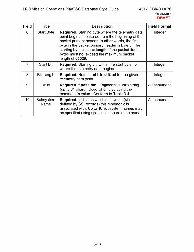
In addition to a mnemonic name, each telemetry record includes fields to identify whichtelemetry packet contains the data and the exact location within the packet. All theavailable fields and LRO defined requirements for those fields are outlined in Table 3-2.Appendix A provides an example of a telemetry SDB file that shows how these fieldsmay be defined.
Please note that the M&T record type is not an ITOS recognized record type. It is acombination of the ITOS recognized TLM and PKT record types. A custom script mustbe used in order to build the ITOS database from the SDB files containing the M&Trecords. This script will break apart the M&T record type into the TLM and PKT recordtypes that ITOS does recognize. More details concerning the script will be supplied inthe T&C Database Management Plan.
TypeRequired. Describes type of record to follow. Fortelemetry, use ‘M&T’.
Alphanumeric
2 OperationSymbol
Required. Contains an operation symbol, either`+' or `-'. The `+' symbol means the record hasnew or updated information; the `-' symbol meansthe information for the identifier should be deletedfrom the existing database. Note that deleting atelemetry mnemonic definition will delete alloccurrences of that mnemonic in all packets.Notice that in order to change an identifier, suchas a telemetry mnemonic name, you must deletethe existing record and add a new record with thesame data, but a different name. If you wish tomove a mnemonic's value from one source packetto another, you must remember to delete the `pkt'entry for the mnemonic in the first packet. Ifrecords are not deleted as required, the databasewill be cluttered with extraneous information andground system performance may be degraded.
Symbol
3 Mnemonic Required. Name of the telemetry data point.Follow naming guidelines in Section 3.1.1.
Alphanumeric
4 Packet ID Required. Application ID (APID) Integer 5 Data Type Required. The size of the mnemonic's value, in
bits or, if the ``type'' is a string type, in bytes. Ifblank, this field value will be inferred from thetype, if possible. For example, a U12 defaults to 16bits. Signed and unsigned integers may not belarger than 32 bits; floating-point values may be32 or 64 bits; and strings have no default size.Note that the size given here is used to limit therange of values that STOL may assign to amnemonic. For example, a size of 2 bits limits anunsigned integer mnemonic's values to the range0 to 3. See Section the ITOS documentation foradditional details on data types.
Field Title Description Field Format 6 Start Byte Required. Starting byte where the telemetry data
point begins, measured from the beginning of thepacket primary header. In other words, the firstbyte in the packet primary header is byte 0. Thestarting byte plus the length of the packet item inbytes must not exceed the maximum packetlength of 65529.
Integer
7 Start Bit Required. Starting bit, within the start byte, forwhere the telemetry data begins
Integer
8 Bit Length Required. Number of bits utilized for the giventelemetry data point
Integer
9 Units Required if possible. Engineering units string(up to 64 chars). Used when displaying themnemonic's value. Conform to Table 3-4.
Alphanumeric
10 SubsystemName
Required. Indicates which subsystem(s) (asdefined by SSI records) this mnemonic isassociated with. Up to 16 subsystem names maybe specified using spaces to separate the names.
Field Title Description Field Format 11 Event Flag Single alphanumeric character, used to mark
mnemonics, which are used to telemeterspacecraft events. This field indicates eventpackets that contain an event code, a subsystemidentifier, a severity code, and four datapoints.The default is ' '.`C'Event code
`S'Subsystem ID
`R'Severity
`1'Data Point 1
`2'Data Point 2
`3'Data Point 3
`4'Data Point 4
Alphanumeric
12 Limits This field may contain a name, a number, or aname and a number separated by white space. If the field contains a name, that name is the
limit definition (LIM) that specifies thered/yellow limits for this mnemonic. (If the fielddoes not contain a name, the mnemonic hasno red/yellow limits).
If the field contains a number, that number isthe delta limit for the mnemonic.
Floating Point
13 Conversion The name of the analog (ALG) or discrete (DSC)conversion to apply to this mnemonic value whendisplaying the value or if it is referenced throughthe STOL `p@' operator. If blank, the mnemonichas no conversion.
Field Title Description Field Format 15 Initial Value The mnemonic's initial value. Generally, the rule is
to leave blank (uninitialized).Floating Point
16 ReadOnlyFlag
Required. `T' or `F'. If `T', normal STOLassignment directives will not be permitted tochange this mnemonic's value. The default is `F'.
Alphanumeric
17 ArrayLength
Reserved for future use. Array length (default =1).
Integer
18 Array Offset Reserved for future use. The offset, in bits,between array elements. Not used unless themnemonic is an array. If blank, the default valuecomes from field 4. If 0, only one array element isextracted.
Integer
19 Array Index Reserved for future use. Used for mnemonicarrays, the elements of which are not telemeteredat constant intervals in a packet or are not in thesame packet. Normally, array elements are in onepacket at a constant distance from one another.The “offset between array elements” (field 16)gives this constant distance.
Integer
20 Description Required. A brief description of the telemetrypoint identified by the mnemonic (limited to 64characters). For additional detail, the <html>indicator allows an unlimited number of textcharacters to be included.
Alphanumeric
3.2.1.4.5. Limit RecordsThe LIM record defines a limit range for an integer or floating-point telemetry mnemonic.A limit set consists of two concentric ranges called the “yellow limits” and “red limits”. Alimit definition record may contain more than one limit set. The system chooses whichlimit set to apply to a mnemonic using the “limit switch”, explained below. Refer toAppendix A for an example. Refer to the ITOS documentation for adescription/definition of the LIM record fields. A definition in record fields 1-3, and 12 isrequired for LRO.
3.2.1.4.6. Discrete Conversion RecordsDiscrete conversions, defined in DSC records, transform a range of numeric values intoa set of text strings. The telemetry value is compared to each range in the set. If thevalue falls within the specified range, the state text associated with that range isdisplayed. The high value of one range can be the same as the low value of the nextrange; otherwise, overlapping ranges are discouraged. Refer to Appendix A for anexample. Refer to the ITOS documentation for a description/definition of the DSCrecord fields. A definition in record fields 1-6, and 9 is required for LRO.
3.2.1.4.7. Analog Conversion RecordsAnalog conversions, defined in ALG records, transform an integer number of “counts”(the output of an analog to digital converter, for example) into a floating-point value in“engineering units”, such as volts, amps, degrees, etc. The ALG record defines thecoefficients for an 8th order polynomial. The integer or floating-point telemetry value isapplied to the polynomial and the result is a floating-point value. Refer to Appendix A foran example. Refer to the ITOS documentation for a description/definition of the ALGrecord fields. A definition in record fields 1-12 is required for LRO.
3.2.1.4.8. Telemetry Packet Header RecordsAn exception to the general telemetry mnemonic naming convention is for telemetrypacket header field mnemonics, which will be standardized with the format of the singlecharacter ‘H’, followed by a three hexidecimal-digit telemetry packet Application ID(APID) and a field name, respectively. Table 3-3 contains the fields for a representativepacket, APID xxx. Please note that not all packet secondary headers will be the samefor all APIDs, so please use this table as a guide instead of the standard with respect tothe secondary header. Packet header records shall be included as M&T records in alltelemetry SDB files at the start of each APID for that subsystem.
Table 3-3: M&T Telemetry Packet Header Records
Mnemonic StartByte
StartBit
Length inBits
DataType Description
HxxxPKTVNO 0 0 3 U1 APID xxx Packet ID VersionNumber
HxxxPCKT 0 3 1 U1 APID xxx Packet ID TypeHxxxSHDF 0 4 1 U12 APID xxx Packet ID Secondary
HxxxSUBS 10 0 16 U12 APID xxx System TimeSubseconds
3.2.1.5. Pseudo-telemetry SDB File
3.2.1.5.1. Subsystem IdentifiersPseudo-telemetry may be assigned to one or more subsystems. The subsystem nameis used to limit database searches or reports and for general information. Subsystemidentifiers (SSI record type) have a maximum length of 15 characters, and must startwith the assigned two-character prefix from Table 3-1. These records will be includedas part of the pseudo-telemetry SDB file. Refer to Appendix B for an example.
3.2.1.5.2. Telemetry RecordsThe pseudo-telemetry SDB file assigns each pseudo-telemetry data point to arecognizable name, or mnemonic, and is defined by a telemetry record (TLM recordtype). The TLM records will be organized by subsystem.
In addition to a mnemonic name, each telemetry record includes fields to identify otherattributes of the pseudo-telemetry point. Refer to the ITOS Database Buildingdocumentation for the definition of and more information on the TLM record. AppendixB provides an example of a Pseudo-telemetry SDB file that shows how these fields maybe defined. A definition in record fields 1-3, 5, 8 if possible, and 14-15 is required forLRO.
Please note that LIM, DSC and ALG records must also be included in the pseudo-telemetry SDB file if such has been defined in the TLM record of the pseudo_telemetrySDB file. Please follow the same guidelines for these records as explained in Sections3.2.1.45 – 7. Also, note that packet header information is not to be included in thepseudo-telemetry SDB, since pseudo-telemetry is not contained within a CCSDSpacket.
3.2.1.6. Command SDB FileThe command SDB file is comprised of all command-related records (CMD, FLD, andSUB record types). The following sections define the content and format of eachcommand record type.
3.2.1.6.1. Command RecordsCommand records are to be organized in ascending order by APID and FunctionCode/Command Type, respectively. Refer to the ITOS Database Buildingdocumentation for the definition of and more information on the CMD record. AppendixC provides an example of a Command SDB file that shows how these fields may bedefined. A definition in record fields 1-6, 9-11, and 15 is required for LRO.
3.2.1.6.2. Command Field RecordsFor commands that require commandable inputs, the command field record (FLDrecord type), also called a submnemonic, is utilized. These records will immediatelyfollow the associated CMD record. Refer to the ITOS Database Building documentationfor the definition of and more information on the FLD record. Refer to Appendix C foran example. A definition in record fields 1-5, 7, 8 if applicable, 9, and 13-14 is requiredfor LRO.
Note that the “Field Name” (field 3) does not require the pre-defined subsystem prefix,whereas the “Discrete Set Name” (field 13) does.
3.2.1.6.3. Command Discrete Conversion Records
For commands that include command field records, a discrete conversion record (SUBrecord type) may be defined to convert a numerical command input to an alphanumericdiscrete name. For example, a value of zero (0) may correspond to an “ON” state and avalue of one (1) may correspond to an “OFF” state. This allows the user to use “ON”and “OFF” rather than memorizing which function corresponds to 0 or 1. Thissignificantly increases the usability of the command. Similarly, if a command fieldneeds to be commandable, but is commonly set to the same value, the special name"default" may be used to represent the default value when no other value is specified.This allows the user to use the command field when needed, but otherwise omit it if thedefault value is acceptable. If a “default” conversion and value are not identified for agiven field, the field will always require an input value to be commanded.
In the SDB files, these records will immediately follow the associated FLD record(s).Refer to the ITOS Database Building documentation for the definition of and moreinformation on the SUB record. Refer to Appendix C for an example. A definition in allSUB record fields 1-7 is required for LRO.
3.2.2. SummaryThe following provides a summary of the guidelines when creating and maintaining SDBfiles to ensure readability and usability:
a. Within each record type, fixed column widths will be used for each field toimprove readability.
b. Comments and blank lines will be used liberally to distinguish between sets oftelemetry packets, commands with multiple “FLD”/”SUB” records, andconfiguration control information, etc.
c. In subsystem telemetry SDB files, the “M&T” records will be specified in thesame byte order as the data is organized in the telemetry packet.
d. The “M&T”, “DSC”, “ALG”, and “LIM” records for a given telemetry mnemonic willhave unique names and be contained in the same file. This is the preferredmethod. However, if specific “DSC”, “ALG”, or “LIM” records are to be used byseveral subsystems, they may be defined in the SDB files of only one of the
subsystems. CAUTION: This requires careful coordination with other SDB filedevelopers to ensure that the needed records are defined and not mistakenlydeleted.
e. In command definitions, the “FLD” records for a given command will immediatelyfollow the “CMD” records for that command.
f. In command definitions, the “SUB” records for a given command will immediatelyfollow the “FLD” records for that command.
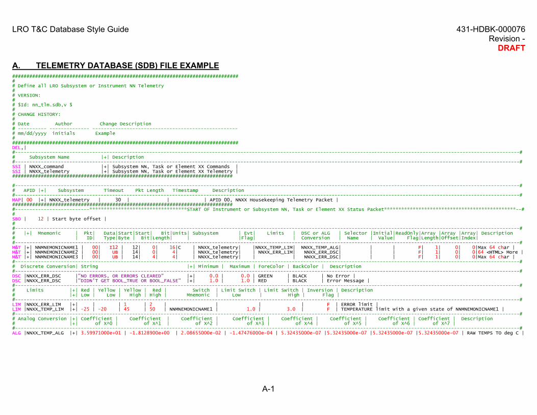
A. TELEMETRY DATABASE (SDB) FILE EXAMPLE################################################################################# Define all LRO Subsystem or Instrument NN Telemetry## VERSION:## $Id: nn_tlm.sdb,v $## CHANGE HISTORY:## Date Author Change Description# ---------- -------------- ---------------------------------------------------# mm/dd/yyyy initials Example################################################################################DEL,|#---------------------------------------------------------------------------------------------------------------------------------------------------------------------------------## Subsystem Name |+| Description#---------------------------------------------------------------------------------------------------------------------------------------------------------------------------------#SSI | NNXX_command |+| Subsystem NN, Task or Element XX Commands |SSI | NNXX_telemetry |+| Subsystem NN, Task or Element XX Telemetry |#############################################################################
#---------------------------------------------------------------------------------------------------------------------------------------------------------------------------------## APID |+| Subsystem Timeout Pkt Length Timestamp Description#---------------------------------------------------------------------------------------------------------------------------------------------------------------------------------#MAP| 00 |+| NNXX_telemetry | 30 | | | APID 00, NNXX Housekeeping Telemetry Packet |##############################################################################--------------------------**********************************START OF Instrument or Subsystem NN, Task or Element XX Status Packet**********************************************--##SBO | 12 | Start byte offset |##---------------------------------------------------------------------------------------------------------------------------------------------------------------------------------## |+| Mnemonic | Pkt| Data|Start|Start| Bit|Units| Subsystem | Evt| Limits | DSC or ALG | Selector |Initial|ReadOnly|Array |Array |Array| Description# | ID| Type|Byte | Bit|Length| | |Flag| | Conversion | Name | Value| Flag|Length|Offset|Index|#---------------------------------------------------------------------------------------------------------------------------------------------------------------------------------#M&T |+| NNMNEMONICNAME1 | 00| I12 | 12| 0| 16|C | NNXX_telemetry| |NNXX_TEMP_LIM| NNXX_TEMP_ALG| | | F| 1| 0| 0|Max 64 char |M&T |+| NNMNEMONICNAME2 | 00| UB | 14| 0| 4| | NNXX_telemetry| | NNXX_ERR_LIM| NNXX_ERR_DSC| | | F| 1| 0| 0|64 <HTML> More |M&T |+| NNMNEMONICNAME3 | 00| UB | 14| 4| 4| | NNXX_telemetry| | | NNXX_ERR_DSC| | | F| 1| 0| 0|Max 64 char |#---------------------------------------------------------------------------------------------------------------------------------------------------------------------------------## Discrete Conversion| String |+| Minimum | Maximum | ForeColor | BackColor | Description#---------------------------------------------------------------------------------------------------------------------------------------------------------------------------------#DSC |NNXX_ERR_DSC |"NO ERRORS, OR ERRORS CLEARED" |+| 0.0 | 0.0 | GREEN | BLACK | No Error |DSC |NNXX_ERR_DSC |"DIDN'T GET BOOL_TRUE OR BOOL_FALSE" |+| 1.0 | 1.0 | RED | BLACK | Error Message |#---------------------------------------------------------------------------------------------------------------------------------------------------------------------------------## Limits |+| Red | Yellow | Yellow | Red | Switch | Limit Switch | Limit Switch | Inversion | Description# |+| Low | Low | High | High | Mnemonic | Low | High | Flag |#---------------------------------------------------------------------------------------------------------------------------------------------------------------------------------#LIM |NNXX_ERR_LIM |+| | | 1 | 2 | | | | F | ERROR limit |LIM |NNXX_TEMP_LIM |+| -25 | -20 | 45 | 50 | NNMNEMONICNAME1 | 1.0 | 3.0 | F | TEMPERATURE limit with a given state of NNMNEMONICNAME1 |#---------------------------------------------------------------------------------------------------------------------------------------------------------------------------------## Analog Conversion |+| Coefficient | Coefficient | Coefficient | Coefficient | Coefficient | Coefficient | Coefficient | Coefficient | Description# |+| of X^0 | of X^1 | of X^2 | of X^3 | of X^4 | of X^5 | of X^6 | of X^7 |#-------------------------------------------------------------- ------------------------------------------------------------------------------------------------------------------#ALG |NNXX_TEMP_ALG |+| 3.59971000e+01 | -1.8128900e+00 | 2.08655000e-02 | -1.47476000e-04 | 5.32435000e-07 |5.32435000e-07 |5.32435000e-07 |5.32435000e-07 | RAW TEMPS TO deg C |
################################################################################# Define all LRO Subsystem/Instrument X Telecommands## VERSION:## $Id: nn_cmd.sdb,v $## CHANGE HISTORY:## Date Author Change Description# ---------- -------------- ---------------------------------------------------# mm/dd/yyyy initials Example################################################################################DEL,|
#--------------------------**********************************START OF Instrument or Subsystem NN, Task or Element XX COMMANDS**********************************************-------#
#--------------------------**********************************END OF Instrument or Subsystem NN, Task or Element XX COMMANDS**********************************************---------#
D. ACRONYM LISTACS Attitude Control SystemALG Analog Conversion Algorithm Definition RecordAPID Application IdentificationC&DH Command and Data HandlingCCB Configuration Control BoardCM Configuration ManagementCMD Command RecordCMO Configuration Management OfficeCRaTER Cosmic Ray Telescope for Effects of RadiationCVS Current Version SystemDB DatabaseDLRE Diviner Lunar Radiometer ExperimentDSC Discrete Definition RecordFLD Command Field (Submnemonic)FSW Flight SoftwareGN&C Guidance, Navigation and ControlGSE Ground Support EquipmentGSFC Goddard Space Flight CenterHGA High Gain AntennaHK HousekeepingI&T Integration and TestITOS Integrated Test and Operations SystemLAMP Lyman-Alpha Mapping ProjectLEND Lunar Exploration Neutron DetectorLIM Limit Definition RecordLOLA Lunar Orbiter Laser AltimeterLRO Lunar Reconnaissance OrbiterLROC Lunar Reconnaissance Orbiter CameraM&T Telemetry RecordNASA National Aeronautics and Space AdministrationPKT PacketRLEP Robotic Lunar Exploration ProgramRF Radio FrequencyS/C or SC SpacecraftSA Solar ArraySBO Start Byte OffsetSDB Single Database FileSSI Subsystem IdentifierSUB Submnemonic Discrete DefinitionT&C Telemetry and CommandTBD To Be DeterminedTBR To Be ResolvedTLM TelemetryUV Ultraviolet