70
Penn Seminar January 2011 1 LSST Large Synoptic Survey Telescope R. Van Berg January 18, 2011

Penn Seminar January 2011 1
LSSTLarge Synoptic Survey Telescope
R. Van Berg
January 18, 2011

Penn Seminar January 2011 2
Synoptic?
• syn·op·tic (s-nptk) also syn·op·ti·cal (-t-
kl)adj.
• 1. Of or constituting a synopsis; presenting
a summary of the principal parts or a
general view of the whole.

Penn Seminar January 2011 3
Preface
Introduction
LSST System Design
System Performance
Education and Public Outreach
The Solar System
Stellar Populations
Milky Way & Local Volume Structure
The Transient & Variable Universe
Galaxies
Active Galactic Nuclei
Supernovae
Strong Lenses
Large-Scale Structure
Weak Lensing
Cosmological Physics
Dark
Energ
y
www.lsst.org/lsst/scibook

Penn Seminar January 2011 4
“The committee recommends that LSST be submitted immediately for NSF's
Major Research Equipment and Facilities Construction (MREFC)
consideration with a view to achieving first light before the end of the decade.
The top rank accorded to LSST is a result of (1) its compelling science case
and capacity to address so many of the science goals of this survey and (2)
its readiness for submission to the MREFC process as informed by its
technical maturity, the survey's assessment of risk, and appraised
construction and operations costs. Having made considerable progress in
terms of its readiness since the 2001 survey, the committee judged that
LSST was the most ready-to-go.“
August 13, 2010
Decadal Survey

Penn Seminar January 2011 5
The LSST Project – ~ x $108
• Telescope & Site
– Telescope Mount
– Mirrors (M1, M2, M3)
– Observatory + base facility +….
• Data Management
– Data movement, storage, analysis
• Camera
– Lenses, filters, sensors, electronics, etc.
NSF
DOE

Penn Seminar January 2011 6NGC7331

Penn Seminar January 2011 7
The LSST Telescope
Secondary mirror
(behind conical
light baffle)
Primary and
tertiary mirrors
Camera mounted through
secondary mirror
Platforms for
accessing camera
Relevant Telescope Features
3 mirror optical design
Moving structure: 300 tons
Altitude/azimuth rotation axes
Max azimuth axis accel: 10.5 deg/sec2
Max elevation axis accel: 5.25 deg/sec2
Camera is cantilevered off the Top End Assembly near
the center of rotation
Camera normally looks down when telescope is pointing
near zenith
Top End Assembly
support structure

Penn Seminar January 2011 8
Telescope Optics
• f/1.23
• < 0.20 arcsec FWHM images in six bands:
0.3 - 1 m
• 3.5 FOV
• Etendue = 319 m2deg2

Penn Seminar January 2011 9
Primary/Tertiary Mirror (in fabrication)

Penn Seminar January 2011 10
Large machinery, large piece of glass, nm precision

Penn Seminar January 2011 11
The Telescope and Site includes the summit and base
facilities, telescope system, & calibration hardware
Base Facility in La Serena
1,380 m2 service and
maintenance facility
30 m diameter domeControl room and heat
producing equipment
1.2 m diameter
atmospheric
telescope
Wind and light baffle
300 ton telescope
Service and
maintenance cranes

Penn Seminar January 2011 12
La Serena
Base Facility
AURA property
0 10 20 km LSST Site
CTIO
N
La Serena
Coquimbo
Gemini &
SOAR
Embalse
Puclaro
airport
Vicuña
puerto
The site has been chosen on Cerro Pachón, Chile

Penn Seminar January 2011 13
Summit facility final design under contract with
ARCADIS Geotecnica, Santiago Chile
50
m
100m 150
m

Penn Seminar January 2011 14
Telescope Dome – an interesting set of
challenges
~14Deg Stray
Light Band
3.5Deg
FOV

Penn Seminar January 2011 15
M57

Penn Seminar January 2011 16
Telescope Mount
Deployable
Platform x2
Tuned Mass
Dampers x4Balancing
System x 4
Elevation Cable
Drape x2
Mirror
Cover
Azimuth
Drives
4 or 8
Elevation
Drives x4
Hydrostatic Azimuth Bearings
Hydrostatic Elevation Bearing
Location of Azimuth
Maypole Cable Drape
Deployable
Platform x2
Tuned Mass
Dampers x4Balancing
System x 4
Elevation Cable
Drape x2
Mirror
Cover
Azimuth
Drives
4 or 8
Elevation
Drives x4
Hydrostatic Azimuth Bearings
Hydrostatic Elevation Bearing
Location of Azimuth
Maypole Cable Drape
Moving structure: 300 tons
Drive power: 450 hp
Damping: Tuned masses raise damping to 5%
First Frequency: 8.2 hz (loaded structure on
bearings, pier, and summit rock)

Penn Seminar January 2011 17
M1M3 System
Cell deck plate with
pneumatic support actuators
Cell deck plate support
girders (blue)
M1M3 mirror within
Light baffle ring
Mirror location
Hardpoint
Structure (red)
Vacuum support
trusses (green)
Metrology laser tracker
access stand and support tube (gray)Cell shell and floor plate
Stiffened against vacuum load
Cutaway View

Penn Seminar January 2011 18
Mirror supports and actuators

Penn Seminar January 2011 19
M2 Substrate purchased and completed by
Corning using LSST non-federal funding
• M2 Blank Complete & Delivered in November 2009
– All Requirements Satisfied 2 Months Early
– Acid Etched Rear/Side Surfaces Ready for Pad Bonding
– CX Surface Contour Grind ~40μm from Final Mirror Figure
Fusion Seal Firing Complete Sag Mandrel Loading Sag to Meniscus Shape Sagged Surface Generating
Acid Etch Complete
CX Contour
Grind Complete
Final Acceptance Complete Delivery to Storage

Penn Seminar January 2011 20
Hickson92

Penn Seminar January 2011 21
Data Management
• Data from Camera –
– 3 GigaPixels, 2 Bytes/Pixel = 6GB – every 18 s (no “Trigger”!!!)
– 1200 GB / hour 12 TB / observing night (ATLAS ~ 16TB/day)
• However, LSST must do fast alerts to Astronomical Community!
Image stream from camera generates real-time transient alerts
– Difference image based
– 60s latency, requires ~37 TFLOPS
• Process entire survey data annually to produce a Data Release
– Self consistent set of data products, all w/same algorithms
– Full survey depth to SRD requirements
– 68 PB images in survey year 10, requires ~ 300 TFLOPS
• Produce calibration data products needed by above
• Support challenging SRD photometry requirements

Penn Seminar January 2011 22
Data Management II
• Make data available to scientists, with enough processing cycles
and support to make it useful
– ~57 TFLOPS, 13 PB storage dedicated for users
Processed
from single
full Imsim
focalplane,
binned 4x4,
with the
markings
for the
individual
amplifiers,
ccds.

Penn Seminar January 2011 23
Data Management World View

Penn Seminar January 2011 24
M15

Penn Seminar January 2011 25
The Camera……
Parameter Value
Diameter 1.65 m
Length 3.7 m
Weight 3000 kg
F.P. Diam 634 mm
1.65 m
5’-5”
– 3.2 Gigapixels
– 0.2 arcsec pixels
– 9.6 square degree FOV
– 2 second readout
– 6 filters

Penn Seminar January 2011 26
Unique technical challenges drive camera design
• Very large field of view (9.6 square degree FOV) implies a physically large focal plane (64-cm diameter) with small (10 m) pixels
• Fast f/1.2 beam leads to short depth-of-focus
• Broad spectral coverage (350 – 1040nm)
• Fast readout to maintain high efficiency given the short exposures (3.2 Gigapixels in 2 seconds)
• Large number of signal lines and large cryostat & low noise
• Camera located in the telescope beam
Mosaic of a large number (189) of sensors with narrow interchip gaps (250 m)
Tight alignment and flatness tolerances (15 m p-to-v) on the sensor array
Deep, fully depleted CCDs, but with minimal charge spreading; 6 filters
Parallelized design and sensors which are highly segmented (16 readout ports)
Electronics must be implemented in the cryostat
Tight constraints on envelope, mass, & heat dissipation

Penn Seminar January 2011 27
Integrated complex sub-systems tightly packaged
within the telescope’s optical constraints
L1 lens
L2 lens
L3 lens
Shutter
Refrigeration
system
Cryostat
Filter(in stored position)
Filter

Penn Seminar January 2011 28
Walk-through 1: Overall view
L1-L2 Lens assembly
Camera housing
and back flange
Penn Seminar January 2011 29
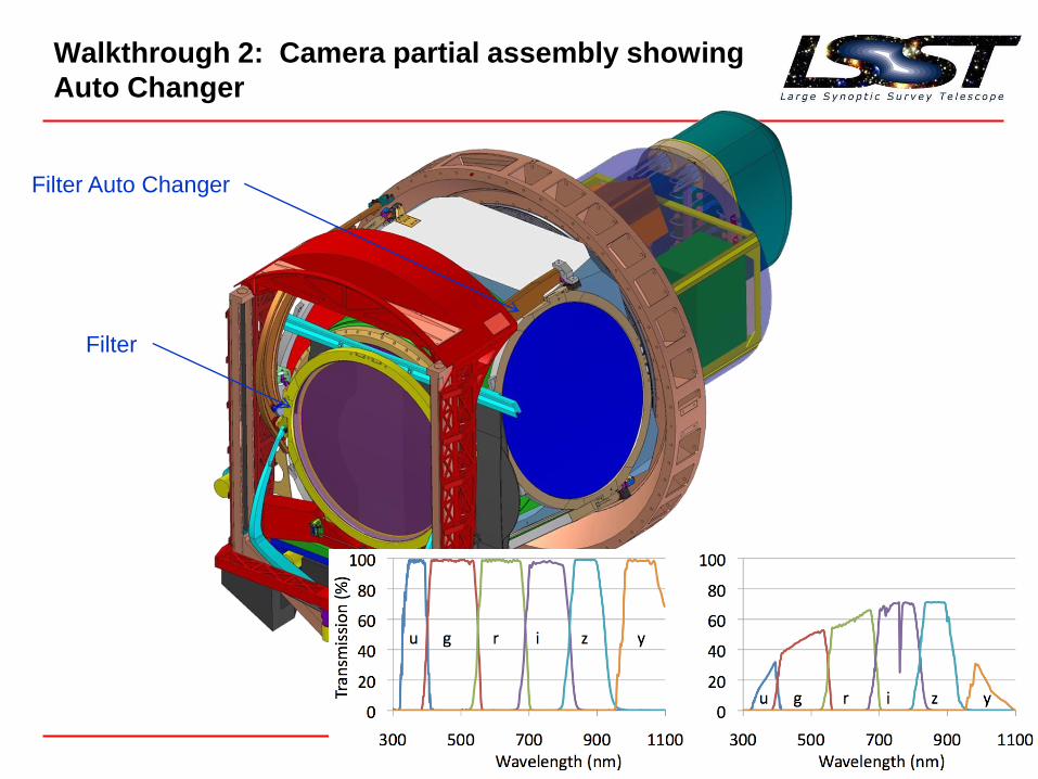
Walkthrough 2: Camera partial assembly showing
Auto Changer
Filter Auto Changer
Filter

Penn Seminar January 2011 30
Walkthrough 3: Camera partial assembly showing
Shutter
Shutter

Penn Seminar January 2011 31
Walkthrough 4: Camera partial assembly showing
Carousel, Cryostat, and detector plane past L3 lens
Filter Carousel
L3 lens
Detector plane

Penn Seminar January 2011 32
Walkthrough 5: Cryostat section showing
detectors, structure and thermal control elements
Grid assembly
Cesic ®L3 lens assembly
Corner Raft Tower
2 guide sensors
1 wavefront sensor
Front end electronics
Science Raft Tower
3 x 3 array of science
sensors
Front end electronics

Penn Seminar January 2011 33
FOCAL PLANE WITH 21 SCIENCE
RAFTS + 4 CORNER RAFTS
The Sensors subsystem consists of the 21 “science
rafts” that make up the 3.2Gpix focal plane
TOWERCCDs + front end electronics
180K operation
An autonomous, fully-testable
and serviceable 144 Mpixel
camera
thermal straps
FEE boards
housing
(cold mass)
cooling
planes
RAFT9 CCDs
coplanarity 6.5 m
4K x 4K CCD10 m pixels, .2 arc sec
extended red response
16 outputs
5 m flatness
Back-side illuminated

Penn Seminar January 2011 34
M1

Penn Seminar January 2011 35
CCDs
• Charge Coupled
Devices –
– Willard Boyle, George
Smith (invented 1969,
Nobel 2009)
• Areal array –
– “parallel shifts” – data
to output register (2k)
– “serial shifts” – data to
electronics (512)

Penn Seminar January 2011 36
CCD Challenges
Large field of view implies
physically large focal
plane (64cm )
Modular mosaic focal
plane construction
21 rafts × 9 4K CCDs/raft
189 CCDs total
3.1Gpix
Fast f/1.2 beam, shallow
depth of focus
Tight alignment and
flatness tolerance
Flatness: 5 m
Alignment (z axis): 10 m
Plate scale 20”/mm Small pixels, close butting Pixel: 10 m
Chip-chip gap: 250 m
Fast readout (2s) with low
noise (5 e-)
Highly parallel readout
electronics
16 amplifiers/4K CCD
Broadband, high spectral
sensitivity
Thick silicon sensor, back
illuminated, AR coat
100 m thickness for IR
sensitivity
Thin conductive window
Seeing-limited image
quality
Internal electric field to
minimize diffusion
High resistivity, biased
silicon (> 3 k -cm, -50V)

Penn Seminar January 2011 37
LSST’s high throughput goals
• The largest focal plane– LSST: 3.2Gpix (189 CCDs)
– PanSTARRS GPC1: 1.4Gpix (60 CCDs)
– HyperSuprimeCam: 940Mpix (112 CCDs)
– DECam: 500Mpix (60 CCDs)
– CFHT MegaCam: 340Mpix (36 CCDs)
• The fastest focal ratio– LSST: f/1.23
– SuprimeCam: f/1.87
– DECam: f/2.7
– PanSTARRS: f/4
– CFHT MegaCam: f/4.2
• The fastest readout time– LSST: 2s
– PanSTARRS GPC1: 6s
– DECam: 17s
– CFHT MegaCam: 40s
– Suprime-Cam: 18s DECam
HSC
MegaCam
GPC1
LSST
Penn Seminar January 2011 38
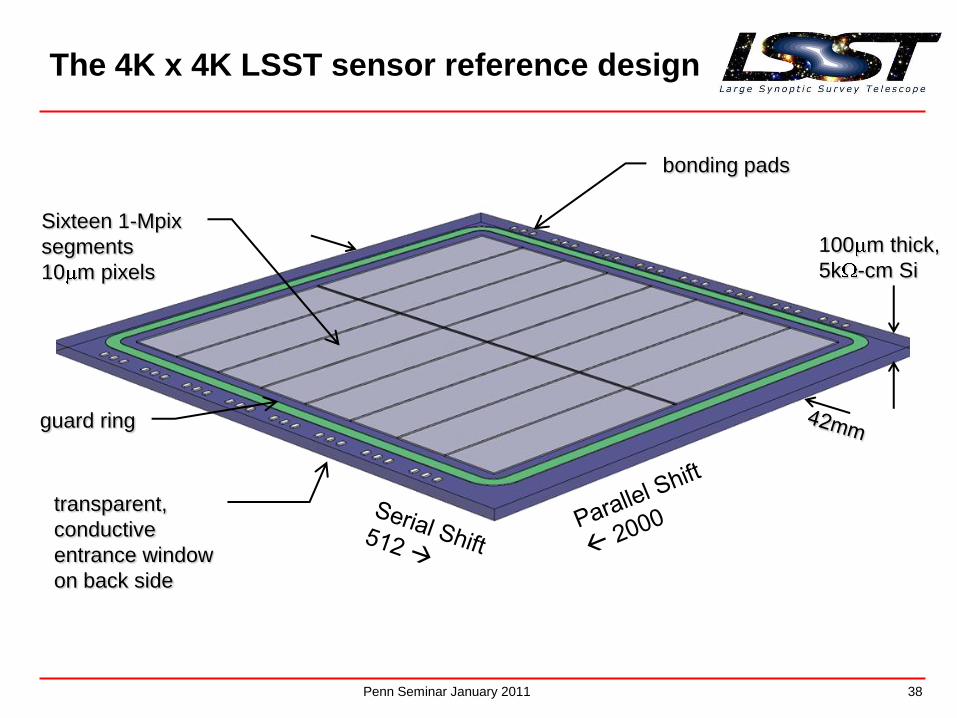
The 4K x 4K LSST sensor reference design
Sixteen 1-Mpix
segments
10 m pixels
bonding pads
guard ring
100 m thick,
5k -cm Si
transparent,
conductive
entrance window
on back side

Penn Seminar January 2011 39
LSST CCD Layout
Penn Seminar January 2011 40
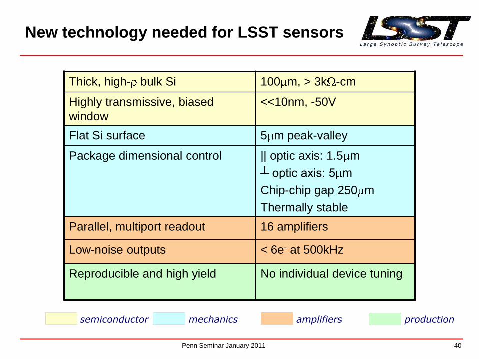
New technology needed for LSST sensors
Thick, high- bulk Si 100 m, > 3k -cm
Highly transmissive, biased
window
<<10nm, -50V
Flat Si surface 5 m peak-valley
Package dimensional control || optic axis: 1.5 m
┴ optic axis: 5 m
Chip-chip gap 250 m
Thermally stable
Parallel, multiport readout 16 amplifiers
Low-noise outputs < 6e- at 500kHz
Reproducible and high yield No individual device tuning
semiconductor mechanics amplifiers production

Penn Seminar January 2011 41
Chip-chip gap 0.25mm (5”)
Image-image gap
1.29mm (26”)
[column direction]
image
area
image
area
image
area
image
area
Image-image gap
2.21mm (44”)
[row direction]
Chip
siz
e 4
2m
m (
14
’)
Edge effects
First one-two pixels from edge
will have larger effective area
due to field distortion

Penn Seminar January 2011 42
Phase 1 device tests -- laboratory
Quantum efficiency
Charge diffusion (xray PSF)
spec.
e2v STA/ITL

Penn Seminar January 2011 43
Phase 1 sensor flatness
e2v
ITL
measurements by P. Takacs, BNL
spec

Penn Seminar January 2011 44
sky flat (I filter) 350nm lab flat
Ion-implant laser anneal
raster pattern
Mask stitching boundaries Radial resistivity
variation
Uninvited guests
Peaks around 0.07 pixel-1
spatial frequencies are associated with ``tree rings''
I. Kotov

Penn Seminar January 2011 45

Penn Seminar January 2011 46
A CCD Electrically…..
SCC
ASPIC
+ 29V
~2mA

Penn Seminar January 2011 47
NGC891

Penn Seminar January 2011 48
Highly integrated, in-cryostat electronics
• Total of 3.024Gpix in focal plane
• Goal is 2s readout with 6e- noise
• CCD readout rate must be below ~600kHz to achieve noise figure
CCDs must be segmented into 1-Mpix segments with individual readout amplifiers
• Choose 4Kx4K CCD format with 16 2048 x 512 pixel segments
– Total wire count to CCDs ~15,000
• Impractical to take this many wires through vacuum barrier
Implement compact (ASIC-based) electronics chain in cryostat
ASPIC (video processing) SCC (clock/bias generation)
thermal straps
FEE boards
housing
(cold mass)
cooling
planes
thermal straps
FEE boards
housing
(cold mass)
cooling
planes
TOWER (144Mpix FPA module)

Penn Seminar January 2011 49
Raft-Centric Electronics System
Sensors + Analog
Processing + Clock
and Bias drive
-100C
Digitization, digital
muxing, power regulation,
clock generation, etc.
-40C

Penn Seminar January 2011 50
ASPIC Specifications – IN2P3*(Analog Signal Processing Integrated Circuit)
• Operates at a temperature of 173K
• Noise :– en < 5nV/sqrt(Hz) maximum noise density
– enc < 7μVrms maximum input noise @ 500ns integration time (~2e¯)
– Note : Either or both of the above may be met. If, for example, at very long integration time, en will rise but
enc will fall, and still be an advantage.
• Operation @ 250kHz to 500kHz
• 0.05% maximum crosstalk between channels @ 500kHz
• 100k e¯ full well capacity (350 to 400 mV maximum input)
• 0.5% linearity (defined over 0 to 100k e¯)
• Differential output
• Output load 50pF // 1k
• Power supply 5V / Gnd - reference Vref = 2.5V
• Power dissipation 25mW / channel
• The ASPIC is designed in 0.35μm 5V CMOS technology from AMS.
* With some help from Mitch and John Oliver

Penn Seminar January 2011 51
ASPIC – Correlated Double Sampler /
Dual Slope Integrator

Penn Seminar January 2011 52
SCC - ORNL(Sensor Control Chip)
Load Frequency Rise Time Fall Time
Switch 1_2 340 pF 1 MHz 35.5 ns 32.5 ns
Load Freq Rise Time Fall Time
Switch 1_4 95 nF 1.6 kHz 7.3 us 7.5 us

Penn Seminar January 2011 53
Front End Board - PennTo C
CD
s To B
EB
s
3 ASPICs
(24 Channels)
6 SCCs

Penn Seminar January 2011 54
SPI bus
CCD Timing
Power and Bias
SPI CS Address
CCD Data Bus
BEE
CPLD
CCD Clock Select(Based on Geo addr)
ADCInterface
SPI DMUX
ADC DataBuffer
PutForgotten stuff
here
CCD ADCx24
Local Registers
TempSensor
Heater
Geographical Addr
Bias Voltage
CCD Timing
CCD analog signals (24)
ASPIC / SCCSPI Configuration
Temp Sensor
Heater
Power and Bias
Back End Board - Harvard

Penn Seminar January 2011 55
Raft Control Module - Harvard
SPI bus
CCD Timing
Power and Bias
SPI CS Address
CCD Data Bus
RCM
FPGA
CCD Clock Gen(Processor)
Configuration Memory
MGTInterface
CCD DataSDRAM
Slow ControlTemp Calc
Housekeeping(Processor)
USBInterface
TCMInterface
ProcessorMemory
Configuration CPLD
TCM Bus
SDS INTERFACEOptical MGT ADC Data
Interface
PutPower stuff
here
SDS INTERFACEOptical MGT
PutForgotten stuff
here

Penn Seminar January 2011 56
“Vertical Slice Tests” – Penn – ASPIC2

Penn Seminar January 2011 57
ASPC-1
Input (mV) vs. DSI_Out (mV)
y = 4.5565x + 23.493
R2 = 0.9999
0
200
400
600
800
1000
1200
1400
0 50 100 150 200 250 300
DSI_Out Gain:
75 µV per
count
Gain (Input vs.
Output):
4.6 mV out
per mV in
Penn Seminar January 2011 58
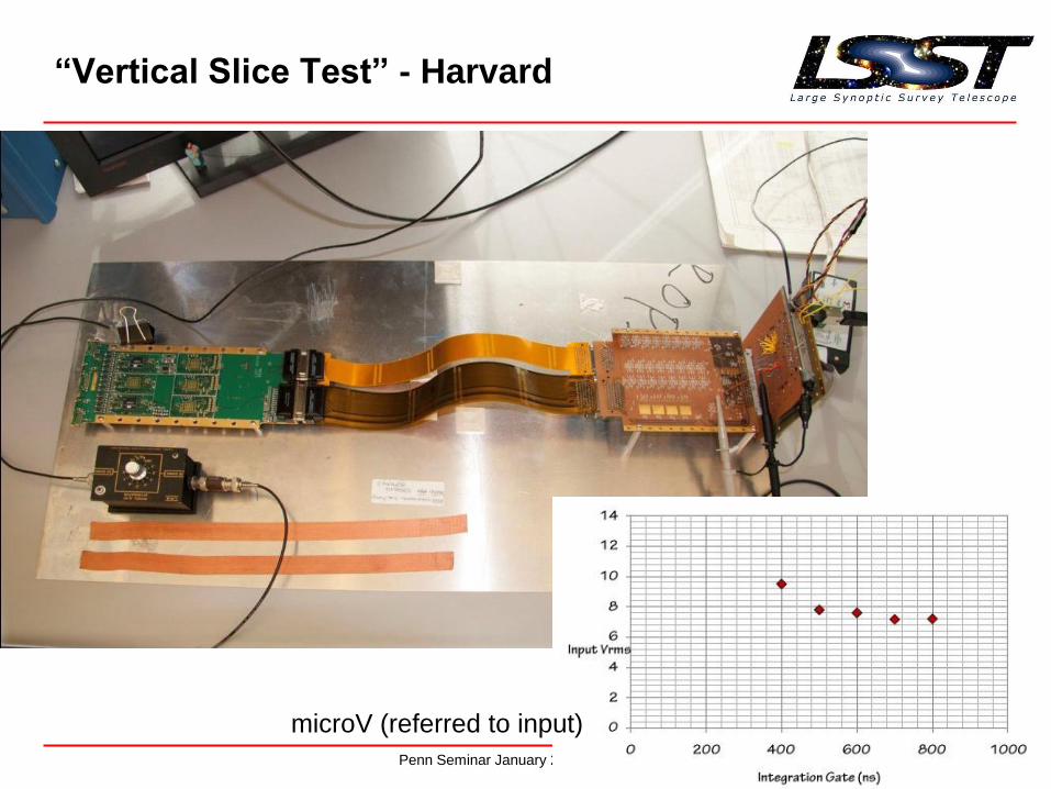
“Vertical Slice Test” - Harvard
microV (referred to input)

Penn Seminar January 2011 59
Other LSST Electronics
• Power Supplies
• Electro-Optical Converters (DAQ)
• Clock generation and distribution
• Controls for:
– Shutter
– Filters
– Pumps
– Cooling

Penn Seminar January 2011 60
Location, Location, Location

Penn Seminar January 2011 61
How to annoy traditionalists….

Penn Seminar January 2011 62
Things not mentioned….
• Thermal design
• Grounding & Shielding
• Optical design / filter characteristics
• Camera and Observatory Control Systems
• Data Acquisition System
• Data bases – meta-data for everything
• Image processing (data cleaning and frame co-adding)
• Vacuum design
• Cleanliness, contamination control
• Focal Plane alignment (ppm!)
• Metrology
• Mechanical design
• Calibration
• Observing simulator / planner

Penn Seminar January 2011 63
First Light – 2018???
Penn Seminar January 2011 64

Penn Seminar January 2011 65
Synoptic!
Penn Seminar January 2011 66
Backup……

Penn Seminar January 2011 67
LSST Boxes

Penn Seminar January 2011 68
Camera Boxology

Penn Seminar January 2011 69
Calyspo has an LSST test camera installed
with phase 1 prototype sensor
• LSST’s 1.2 meter diameter Telescope on Kitt Peak
• Observing Operations conducted regularly
• LSST U, Y3, and Y4 as well as Sloan filter set on telescope
ITL/STA 1920A at Calypso
M1 (R band, 4Kx4K)

Penn Seminar January 2011 70
Data Management III


