136
LT-A750XP/Z USE THIS MANUAL WITH: LT-A750X/Z SERVICE MANUAL (99500-47021-01E) 99501-47050-01E

LT-A750XP/Z
USE THIS MANUAL WITH:LT-A750X/Z SERVICE MANUAL (99500-47021-01E)
9 9 5 0 1 - 4 7 0 5 0 - 0 1 E

FOREWORDThis SUPPLEMENTARY SERVICE MANUAL is a supplement to SUZUKI LT-A750X/Z SERVICE MANUAL.It has been prepared exclusively for the following applicable model.
Applicable model:LT-A750XK9
This supplementary service manual describes only service information which differ from that of the main man-ual. Therefore, whenever servicing the above applicable model, consult this supplement first. And for any sec-tion, item or description not found in this supplement, refer to the main manual below.
Main Manual:
Other information considered as generally known is not included.Read the GENERAL INFORMATION section to familiarize yourself with the vehicle and its maintenance. Usethis section as well as other sections to use as a guide for proper inspection and service.This manual will help you know the vehicle better so that you can assure your customers of fast and reliable ser-vice.
© COPYRIGHT SUZUKI MOTOR CORPORATION 2009
Manual Name Manual No.LT-A750X/ZK9 SERVICE MANUAL 99500-47021-01E
* This manual has been prepared on the basis of the latest specifications at the time of publication. If modifi-cations have been made since then, differences may exist between the content of this manual and theactual vehicle.
* Illustrations in this manual are used to show the basic principles of operation and work procedures. Theymay not represent the actual vehicle exactly in detail.
* This manual is written for persons who have enough knowledge, skills and tools, including special tools, forservicing SUZUKI vehicles. If you do not have the proper knowledge and tools, ask your authorizedSUZUKI motorcycle dealer to help you.
WARNING!
Inexperienced mechanics or mechanics without the proper tools and equipment may not be able toproperly perform the services described in this manual.Improper repair may result in injury to the mechanic and may render the vehicle unsafe for the rider.

00
0
1
2
3
4
5
6
9
Precautions............................................................... 00-iPrecautions ............................................................ 00-1
General Information ................................................... 0-iGeneral Information ...............................................0A-1Maintenance and Lubrication .................................0B-1Service Data...........................................................0C-1
Engine ......................................................................... 1-iPrecautions ...............................................................1-*Engine General Information and Diagnosis ............1A-*Emission Control Devices .......................................1B-*Engine Electrical Devices....................................... 1C-*Engine Mechanical................................................. 1D-*Engine Lubrication System .....................................1E-*Engine Cooling System...........................................1F-*Fuel System ........................................................... 1G-*Ignition System....................................................... 1H-*Starting System....................................................... 1I-1Charging System.....................................................1J-1Exhaust System ......................................................1K-*
Suspension.................................................................2-*Precautions ...............................................................2-*Suspension General Diagnosis...............................2A-*Front Suspension ....................................................2B-*Rear Suspension.................................................... 2C-*Wheels and Tires ................................................... 2D-*
Driveline / Axle ........................................................... 3-iPrecautions ...............................................................3-*Drive Chain / Drive Train / Drive Shaft ...................3A-1Differential ...............................................................3B-*Transfer.................................................................. 3C-*Propeller Shafts...................................................... 3D-*
Brake ........................................................................... 4-iPrecautions ...............................................................4-*Brake Control System and Diagnosis ....................4A-1Front Brakes............................................................4B-*Rear Brakes ........................................................... 4C-*Parking Brake......................................................... 4D-*
Transmission / Transaxle ..........................................5-*Precautions ...............................................................5-*Automatic Transmission..........................................5A-*
Steering....................................................................... 6-iPrecautions .............................................................. 6-1Steering General Diagnosis ...................................6A-1Steering / Handlebar ..............................................6B-1Power Assisted Steering System...........................6C-1
Body and Accessories............................................... 9-iPrecautions ...............................................................9-*Wiring Systems ......................................................9A-1Lighting Systems.................................................... 9B-*Combination Meter / Fuel Meter / Horn.................. 9C-*Exterior Parts ......................................................... 9D-*Body Structure .......................................................9E-1
TABLE OF CONTENTSNOTEFor the screen toned sections with asterisk (*) in the “TABLE OF CONTENTS” below, refer to the same sections of the service manual mentioned in the “FOREWORD” of this manual.


Table of Contents 00- i
00
Section 00
CONTENTS
Precautions
Precautions ...............................................00-1Precautions........................................................... 00-1
Warning / Caution / Note......................................00-*
General Precautions ............................................00-*Precautions for Electrical Circuit Service .............00-*Precautions for EPS (LT-A750XP/ZK9) .............. 00-1
NOTEFor the items with asterisk (*) in the “CONTENTS” below, refer to the same section of the service manual mentioned in the “FOREWORD” of this manual.

00-1 Precautions:
PrecautionsPrecautionsPrecautions
Precautions for EPS (LT-A750XP/ZK9)B931G30000004
EPS Wiring• The EPS parts are connected to various lead wires.
The coupler and lead wire connections, as well as the lead wire and wire harness routings must be done correctly. Make sure that the proper clamps are used and positioned correctly.
NOTEIf all of the connections are not properly connected, the EPS may not operate correctly. For connector and coupler precautions. Refer to “Precautions for Electrical Circuit Service in related manual”.
EPS Control Unit / EPS Body Assembly• Never allow dust or water to contact the EPS control
unit and EPS body assembly.
• Since each component is a high-precision part, great care should be taken not to apply any service impacts during removal and installation.
• The EPS control unit and EPS body assembly cannot be disassembled. Replace the whole unit with a new one.
I931H1000004-01
I931H1000003-02
I931H1000005-01

Table of Contents 0- i
0
Section 0
CONTENTS
General Information
General Information ................................ 0A-1General Description .............................................0A-1
Symbols ...............................................................0A-*Abbreviations .......................................................0A-*SAE-to-Former SUZUKI Term .............................0A-*Vehicle Side View ................................................0A-*Vehicle Identification Number ..............................0A-*Fuel and Oil Recommendation ............................0A-*Engine Coolant Recommendation .......................0A-*BREAK-IN Procedures.........................................0A-*Country and Area Codes .....................................0A-*Wire Color Symbols .............................................0A-*Warning, Caution and Information Labels
Location .............................................................0A-*Abbreviations (LT-A750XP/ZK9).........................0A-1Vehicle Side View (LT-A750XP/ZK9)..................0A-1Country and Area Codes (LT-A750XP/ZK9) .......0A-1Warning, Caution and Information Labels
Location (LT-A750XP/ZK9)...............................0A-2Component Location ........................................... 0A-*
Electrical Components Location ..........................0A-*Specifications.......................................................0A-3
Specifications (LT-A750X/ZK8)............................0A-*Specifications (LT-A750X/ZK9)............................0A-*Specifications (LT-A750XP/ZK9) ........................0A-3
Special Tools and Equipment .............................0A-5Special Tool ........................................................0A-5
Maintenance and Lubrication................. 0B-1Precautions........................................................... 0B-*
Precautions for Maintenance ...............................0B-*General Description ............................................. 0B-*
Recommended Fluids and Lubricants..................0B-*Scheduled Maintenance ...................................... 0B-*
Periodic Maintenance Schedule Chart.................0B-*Lubrication Points ................................................0B-*
Repair Instructions ..............................................0B-1Air Cleaner Element Inspection and Cleaning .....0B-*Exhaust Pipe Bolt and Muffler Bolt Inspection .....0B-*Valve Clearance Inspection and Adjustment .......0B-*Spark Plug Replacement .....................................0B-*Spark Plug Inspection and Cleaning....................0B-*Spark Arrester Cleaning.......................................0B-*Fuel Line Inspection.............................................0B-*
Engine Oil and Filter Replacement ..................... 0B-*Front Differential Gear Oil Inspection.................. 0B-*Front Differential Gear Oil Replacement ............. 0B-*Final Gear Oil Inspection..................................... 0B-*Final Gear Oil Replacement................................ 0B-*Throttle Cable Play Inspection and
Adjustment ........................................................ 0B-*Throttle Body Inspection ..................................... 0B-*Cooling System Inspection.................................. 0B-*Drive V-belt Inspection and Replacement........... 0B-*Drive Shaft Boots Inspection............................... 0B-*Front Brake System Inspection ........................... 0B-*Rear Brake Pedal / Rear Brake (Parking
Brake) Lever Inspection and Adjustment .......... 0B-*Rear Brake Friction Plate Wear Limit
Inspection.......................................................... 0B-*Tire Inspection..................................................... 0B-*Steering System Inspection ................................ 0B-*Toe Adjustment ................................................... 0B-*Suspensions Inspection ...................................... 0B-*Chassis Bolt and Nut Inspection ......................... 0B-*Compression Pressure Check ............................ 0B-*Oil Pressure Check ............................................. 0B-*SDS Check.......................................................... 0B-*Automatic Clutch Inspection................................ 0B-*Air Cleaner Element Inspection and Cleaning
(LT-A750XP/ZK9)..............................................0B-1Steering System Inspection (LT-A750XP/
ZK9) ..................................................................0B-1Toe Adjustment (LT-A750XP/ZK9) .....................0B-2Chassis Bolt and Nut Inspection (LT-A750XP/
ZK9) ..................................................................0B-3Specifications.......................................................0B-4
Tightening Torque Specifications........................0B-4Special Tools and Equipment ............................. 0B-*
Recommended Service Material ......................... 0B-*
Service Data ............................................. 0C-1Specifications.......................................................0C-1
Service Data........................................................ 0C-*Tightening Torque List ........................................ 0C-*Service Data (LT-A750XP/ZK9) ..........................0C-1Tightening Torque List (LT-A750XP/ZK9)...........0C-7
NOTEFor the items with asterisk (*) in the “CONTENTS” below, refer to the same section of the service manual mentioned in the “FOREWORD” of this manual.

0A-1 General Information:
General InformationGeneral InformationGeneral Description
Abbreviations (LT-A750XP/ZK9)B931G30101012
NOTEPlease refer to the LT-A750XK9 (’09-model) service manual for other abbreviations which are not given in this manual.
E: EPS: Electronic Power Steering
Vehicle Side View (LT-A750XP/ZK9)B931G30101013
NOTEDifference between illustration and actual motorcycles may exist depending on the markets.
SUZUKI LT-A750XP (2009-model)
Right Side
Left Side
Country and Area Codes (LT-A750XP/ZK9)B931G30101014
The following codes stand for the applicable country(-ies) and area(-s).
I931G3010001-01
I931G3010002-01
Code Country or Area Effective Frame No.LT-A750XPK9 (P-17) Sweden
5SAAR41P97100001 –
LT-A750XPK9 (P-24) AustraliaLT-A750XPK9 (P-28) CanadaLT-A750XPK9 (P-33) U.S.A.LT-A750XPZK9 (P-17) SwedenLT-A750XPZK9 (P-24) AustraliaLT-A750XPZK9 (P-28) CanadaLT-A750XPZK9 (P-33) U.S.A.
General Information: 0A-2
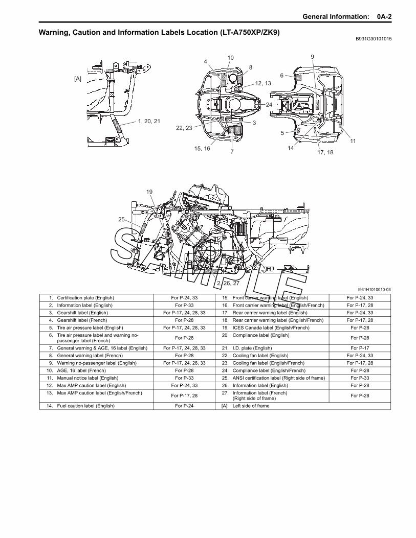
Warning, Caution and Information Labels Location (LT-A750XP/ZK9)B931G30101015
5
1417, 18
11
9
6
3
7
8
10
12, 13
15, 16
4
1, 20, 21
22, 23
24
19
25
2, 26, 27
[A]
I931H1010010-03
1. Certification plate (English) For P-24, 33 15. Front carrier warning label (English) For P-24, 332. Information label (English) For P-33 16. Front carrier warning label (English/French) For P-17, 283. Gearshift label (English) For P-17, 24, 28, 33 17. Rear carrier warning label (English) For P-24, 334. Gearshift label (French) For P-28 18. Rear carrier warning label (English/French) For P-17, 285. Tire air pressure label (English) For P-17, 24, 28, 33 19. ICES Canada label (English/French) For P-286. Tire air pressure label and warning no-
passenger label (French) For P-28 20. Compliance label (English) For P-28
7. General warning & AGE, 16 label (English) For P-17, 24, 28, 33 21. I.D. plate (English) For P-178. General warning label (French) For P-28 22. Cooling fan label (English) For P-24, 339. Warning no-passenger label (English) For P-17, 24, 28, 33 23. Cooling fan label (English/French) For P-17, 28
10. AGE, 16 label (French) For P-28 24. Compliance label (English/French) For P-2811. Manual notice label (English) For P-33 25. ANSI certification label (Right side of frame) For P-3312. Max AMP caution label (English) For P-24, 33 26. Information label (English) For P-2813. Max AMP caution label (English/French) For P-17, 28 27. Information label (French)
(Right side of frame) For P-28
14. Fuel caution label (English) For P-24 [A]: Left side of frame

0A-3 General Information:
SpecificationsSpecifications (LT-A750XP/ZK9)
B931G30107003NOTEThese specifications are subject to change without notice.
Dimensions and curb mass
Engine
Drive train
Item Specification Remark
Overall length 2 115 mm (83.3 in) P-28, 332 165 mm (85.2 in) P-17, 24
Overall width 1 210 mm (47.6 in) P-28, 331 250 mm (49.2 in) P-17, 24
Overall height 1 285 mm (50.6 in)Wheelbase 1 285 mm (50.6 in)Ground clearance 260 mm (10.2 in)Seat height 920 mm (36.2 in)
Curb mass 305 kg (672 lbs) P-28, 33307 kg (677 lbs) P-17, 24
Front track 940 mm (37.0 in)Rear track 920 mm (36.2 in)
Item Specification RemarkType 4-stroke, liquid-cooled, DOHCNumber of cylinders 1Bore 104.0 mm (4.094 in)Stroke 85.0 mm (3.346 in)Displacement 722 cm3 (44.1 cu. in)Compression ratio 10.0 : 1Fuel system Fuel injectionAir cleaner Paper elementStarter system Electric starterLubrication system Wet sumpIdle speed 1 300 ± 100 r/min
Item Specification RemarkClutch Wet shoe, automatic, centrifugal typeTransmission CVT (V-belt)Transfer 2-speed forward with reverseGearshift pattern
Transmission AutomaticTransfer L-H-N-R (Hand operated)
Automatic transmission ratio Variable change (2.763 – 0.78)Secondary reduction ratio 2.158 (40/21 x 17/15)Final reduction ratio(Front & Rear) 3.600 (36/10)
Transfer gear ratio
Low 2.562 (41/16)High 1.240 (31/25)
Reverse 1.882 (32/17)Drive system Shaft drive

General Information: 0A-4
Chassis
Electrical
Capacities
Item Specification RemarkFront suspension Independent, double wishbone, coil spring, oil dampedRear suspension Independent, double wishbone, coil spring, oil dampedFront wheel travel 170.5 mm (6.7 in)Rear wheel travel 195 mm (7.7 in)Caster 3.3°Trail 16.7 mm (0.66 in)Toe-out 5 mm (0.20 in)Camber –1.3°Steering angle 46° (right & left)Turning radius 3.1 m (10.2 ft)Front brake Disc brake, twinRear brake Sealed oil-bathed multi-discFront tire size AT25 x 8-12 , tubelessRear tire size AT25 x 10-12 , tubeless
Item Specification RemarkIgnition type Electronic ignition (CDI)Ignition timing 7° B.T.D.C. at 1 300 r/minSpark plug NGK CR6E or DENSO U20ESR-NBattery 12 V 64.8 kC (18 Ah)/10 HRGenerator Three-phase A.C. generatorMain fuse 30 AFuse 10/10/10/10/15/15 AEPS fuse 40 AHeadlight 12 V 35/35 W x 2Auxiliary light 12 V 35/35 WBrake light/Taillight 12 V 21/5 WReversing light 12 V 21 W P-17Speedometer light LEDNeutral indicator light LEDHigh beam indicator light LED P-17Coolant temperature/FI indicator light LED
Reverse indicator light LEDDiff-lock indicator light LEDEPS indicator light LED
Item Specification RemarkFuel tank 17.5 L (4.6/3.8 US/lmp gal)
Engine oil
Oil change 2 300 ml (2.4/2.0 US/lmp qt)With filter change 2 500 ml (2.6/2.2 US/lmp qt)
Overhaul 3 000 ml (3.2/2.6 US/lmp qt)Differential gear oil 500 ml (16.9/17.6 US/lmp oz)Final gear oil 770 ml (26.0/27.1 US/lmp oz)Coolant 2.5 L (2.6/2.2 US/lmp qt)

0A-5 General Information:
Special Tools and EquipmentSpecial Tool
B931G30108002
09900–06107Snap ring remover (Open type)
09900–20102Vernier calipers (200 mm)
09900–25008Multi circuit tester set
09900–25009Needle-point probe set
09904–41010SUZUKI Diagnostic system set
09924–84521Bearing installer set
09930–30721Rotor remover
09930–44530Rotor holder
09930–82710Mode select switch
09930–82720Mode selection switch
09942–72410Tie-rod end remover
09942–83110Clip remover
09944–36011Steering wheel remover
99565–01010–020CD-ROM Ver.20

Maintenance and Lubrication: 0B-1
General InformationMaintenance and LubricationRepair Instructions
Air Cleaner Element Inspection and Cleaning (LT-A750XP/ZK9)
B931G30206033
Clean elementEvery 1 000 km (600 miles, 3 months)
If the air cleaner is clogged with dust, intake resistance will be increased, with a resultant decrease in power output and an increase in fuel consumption. Check and clean the air cleaner element in the following manner.
CAUTION!
• If driving under dusty conditions, clean the air cleaner element more frequently. The surest way to accelerate engine wear is to operate the engine without the element or to use a torn element. Make sure that the air cleaner is in good condition at all times. Life of the engine depends largely on this component.
• Inspect the air cleaner element for tears. A torn element must be replaced.
1) Remove the air cleaner element. Refer to “Air Cleaner Element Removal and Installation in Section 1D in related manual”.
2) Separate the polyurethane from element.
3) Fill a wash pan of a proper size with a non-flammable cleaning solvent. Immerse the air cleaner element in the cleaning solvent and wash it.
4) Press the air cleaner element between the palms of both hands to remove the excess solvent: do not twist or wring the element or it will tear.
5) Immerse the element in motor oil, and then squeeze out the excess oil leaving the element slightly wet.
6) After cleaning the air cleaner element, reinstall the removed parts.
7) Drain water from the air cleaner box by removing the drain plug.
8) Reinstall the drain plug.
Steering System Inspection (LT-A750XP/ZK9)B931G30206030
Inspect steering systemInitially at 200 km (100 miles, 1 month) and every 1 000 km (600 miles, 3 months) thereafter
Steering should be adjusted properly for smooth turning of handlebars and safe running.1) Place the vehicle on level ground.2) Make sure the tire pressure for right and left tires in
the same and set to the proper specification.3) Set the front wheels in the straight position.4) Place a load of 75 kg (165 lbs) on the seat.
I831G1020002-01
“A”: Non-flammable cleaning solvent“B”: Motor oil SAE #30 or SAE 10W-40
“A”
“B”
I931G3020009-01
I831G1020004-01

0B-2 Maintenance and Lubrication:
5) Measure the distances (“A” and “B”) between the front wheels. Subtract the measurement of “A” from that of “B” to find the toe-out. If the toe-out is not within specification, adjust the tie-rod to the right or left until the toe-out is within the specified range.
Toe-out (“B” – “A”)Standard: 5 ± 4 mm (0.20 ± 0.16 in)
If the toe-out is out of specification, bring it into the specified range. Refer to “Toe Adjustment (LT-A750XP/ZK9) (Page 0B-2)”.
Toe Adjustment (LT-A750XP/ZK9)B931G30206031
Adjust the toe-out as follows:1) Loosen the lock-nuts (1), (2) on each tie-rod.
CAUTION!
• The lock-nuts (2) have left-hand threads.• When loosening and tightening the lock-
nuts, hold the tie-rod end with a open end wrench.
NOTEHold the concave part “a” of tie-rod with a wrench.
2) Temporarily tighten the four lock-nuts.3) Check that the distances “C” and “D” are equal, as
shown. If the distances are not equal, adjust the tie- rod to the right or left until the toe-out is within specification. Check the toe-out again by measuring distances “A” and “B”.
4) If the toe-out is not within specification, repeat the adjustment as above until the proper toe-out is obtained and distances “C” and “D” become equal.
5) After adjustment has been made, tighten the four lock-nuts to the specified torque.
Tightening torqueTie-rod lock-nut (a): 29 N·m (2.9 kgf-m, 21.0 lbf-ft)
I931H1020057-01
FWD
“A”
“B”I831G1020059-04
2
1
1
“a”
“a”
FWDFWD
I931H1020079-02
“C”
Right angle
(90°)
FWD
“A”
“B”
“D”
I831G1020088-04
(a)
(a)
(a)
I831G1020089-01

Maintenance and Lubrication: 0B-3
Chassis Bolt and Nut Inspection (LT-A750XP/ZK9)
B931G30206032
Tighten chassis bolt and nutInitially at 200 km (100 miles, 1 month) and every 1 000 km (600 miles, 3 months) thereafter
Check that all chassis bolts and nuts are tightened to their specified torque.
1 EPS body assembly mounting bolt (Upper) 26 N⋅m (2.6 kgf-m, 19.0 lbf-ft)
2 EPS body assembly mounting nut (Lower) 28 N⋅m (2.8 kgf-m, 20.0 lbf-ft)
3 Steering shaft bolt 26 N⋅m (2.6 kgf-m, 19.0 lbf-ft)
(a)1
I931G3020001-01
(b)2
I931G3020002-01
(a)3
I931G3020003-01
4 Steering shaft upper nut 120 N⋅m (12.0 kgf-m, 87.0 lbf-ft)
5 Tie-rod lock-nut 29 N⋅m (2.9 kgf-m, 21.0 lbf-ft)
6 Rear stabilizer joint nut 60 N⋅m (6.0 kgf-m, 43.5 lbf-ft)
7 Rear brake pedal screw 4.5 N⋅m (0.45 kgf-m, 3.0 lbf-ft)
(c)4
I931G3020004-02
(d)5
(d)5
I931G3020005-02
(e)6
(e)6
I931G3020007-02
(f)7
I931G3020008-01

0B-4 Maintenance and Lubrication:
SpecificationsTightening Torque Specifications
B931G30207001
NOTEThe specified tightening torque is described in the following.“Chassis Bolt and Nut Inspection (LT-A750XP/ZK9) (Page 0B-3)”
Reference:For the tightening torque of fastener not specified in this section, refer to “Tightening Torque List (LT-A750XP/ZK9) in Section 0C (Page 0C-7)”.
Fastening part Tightening torque NoteN⋅m kgf-m lbf-ftTie-rod lock-nut 29 2.9 21.0 (Page 0B-2)

Service Data: 0C-1
General InformationService DataSpecifications
Service Data (LT-A750XP/ZK9)B931G30307003
Valve + Valve GuideUnit: mm (in)
Camshaft + Cylinder HeadUnit: mm (in)
Item Standard Limit
Valve diam. IN. 36.0 (1.42) —EX. 33.0 (1.30) —
Tappet clearance (When cold) IN. 0.10 – 0.20 (0.004 – 0.008) —EX. 0.20 – 0.30 (0.008 – 0.012) —
Valve guide to valve stem clearance IN. 0.010 – 0.037 (0.0004 – 0.0015) —EX. 0.030 – 0.057 (0.0012 – 0.0022) —
Valve guide I.D. IN. & EX. 5.500 – 5.512 (0.2165 – 0.2170) —
Valve stem O.D. IN. 5.475 – 5.490 (0.2156 – 0.2161) —EX. 5.455 – 5.470 (0.2148 – 0.2154) —
Valve stem deflection IN. & EX. — 0.35 (0.014)Valve stem runout IN. & EX. — 0.05 (0.002)Valve head thickness IN. & EX. — 0.5 (0.02)Valve seat width IN. & EX. 0.9 – 1.1 (0.035 – 0.043) —Valve head radial runout IN. & EX. — 0.03 (0.001)Valve spring free length IN. & EX. — 46.1 (1.81)
Valve spring tension IN. & EX. 182 – 210 N (18.6 – 21.4 kgf, 41.0 – 47.2 lbs) at length 36.35 mm (1.43 in) —
Item Standard Limit
Cam height IN. 36.330 – 36.380 (1.4303 – 1.4323) 36.030 (1.4185)EX. 35.300 – 35.350 (1.3898 – 1.3917) 35.000 (1.3780)
Camshaft journal oil clearance IN. & EX. 0.019 – 0.053 (0.0007 – 0.0021) 0.150 (0.0059)Camshaft journal holder I.D. IN. & EX. 22.012 – 22.025 (0.8666 – 0.8671) —Camshaft journal O.D. IN. & EX. 21.972 – 21.993 (0.8650 – 0.8659) —Camshaft runout IN. & EX. — 0.10 (0.004)Cylinder head distortion — 0.05 (0.002)Cam drive idle gear/sprocket thrust clearance 0.15 – 0.27 (0.006 – 0.011) —

0C-2 Service Data:
Cylinder + Piston + Piston RingUnit: mm (in)
Conrod + Crankshaft Unit: mm (in)
Oil Pump
ClutchUnit: mm (in)
Item Standard LimitCompression pressure(Automatic-decomp. actuated) Approx. 1 000 kPa (10.0 kgf/cm2, 142 psi) —
Piston-to-cylinder clearance 0.030 – 0.040 (0.0012 – 0.0016) 0.120 (0.0047)
Cylinder bore 104.000 – 104.015 (4.0945 – 4.0951) Nicks or Scratches
Piston diam. 103.965 – 103.980 (4.0931 – 4.0937)Measure at 15 mm (0.6 in) from the skirt end. 103.880 (4.0898)
Cylinder distortion — 0.05 (0.002)
Piston ring free end gap 1st R Approx. 13.1 (0.52) 10.5 (0.41)2nd RN Approx. 14.6 (0.57) 11.7 (0.46)
Piston ring end gap 1st R 0.10 – 0.25 (0.004 – 0.010) 0.50 (0.020)2nd RN 0.10 – 0.25 (0.004 – 0.010) 0.50 (0.020)
Piston ring-to-groove clearance 1st — 0.180 (0.0071)2nd — 0.150 (0.0059)
Piston ring groove width1st 0.83 – 0.85 (0.0327 – 0.0335)
1.30 – 1.32 (0.0512 – 0.0520) —
2nd 1.01 – 1.03 (0.0398 – 0.0406) —Oil 2.01 – 2.03 (0.0791 – 0.0799) —
Piston ring thickness 1st 0.76 – 0.81 (0.0299 – 0.0319) —1.08 – 1.10 (0.0425 – 0.0433) —
2nd 0.97 – 0.99 (0.0382 – 0.0390) —Piston pin bore I.D. 23.002 – 23.008 (0.9056 – 0.9058) 23.030 (0.9067)Piston pin O.D. 22.992 – 23.000 (0.9052 – 0.9055) 22.980 (0.9047)
Item Standard LimitConrod small end I.D. 23.006 – 23.014 (0.9057 – 0.9061) 23.040 (0.9071)Conrod deflection — 3.0 (0.12)Conrod big end side clearance 0.10 – 0.75 (0.004 – 0.030) 1.0 (0.04)Conrod big end width 24.95 – 25.00 (0.982 – 0.984) —Crank web to web width 72.9 – 73.1 (2.87 – 2.88) —Crankshaft runout — 0.08 (0.003)
Item Standard Limit
Oil pressure (at 60 °C, 140 °F)140 – 180 kPa
(1.4 – 1.8 kgf/cm2, 20 – 26 psi)at 3 000 r/min
—
Item Standard LimitClutch wheel I.D. 140.0 – 140.2 (5.512 – 5.520) 140.5 (5.53)
Clutch shoe — No groove at any part
Clutch engagement r/min 1 500 – 2 000 r/min —Clutch lock-up r/min 3 500 – 4 000 r/min —
Service Data: 0C-3
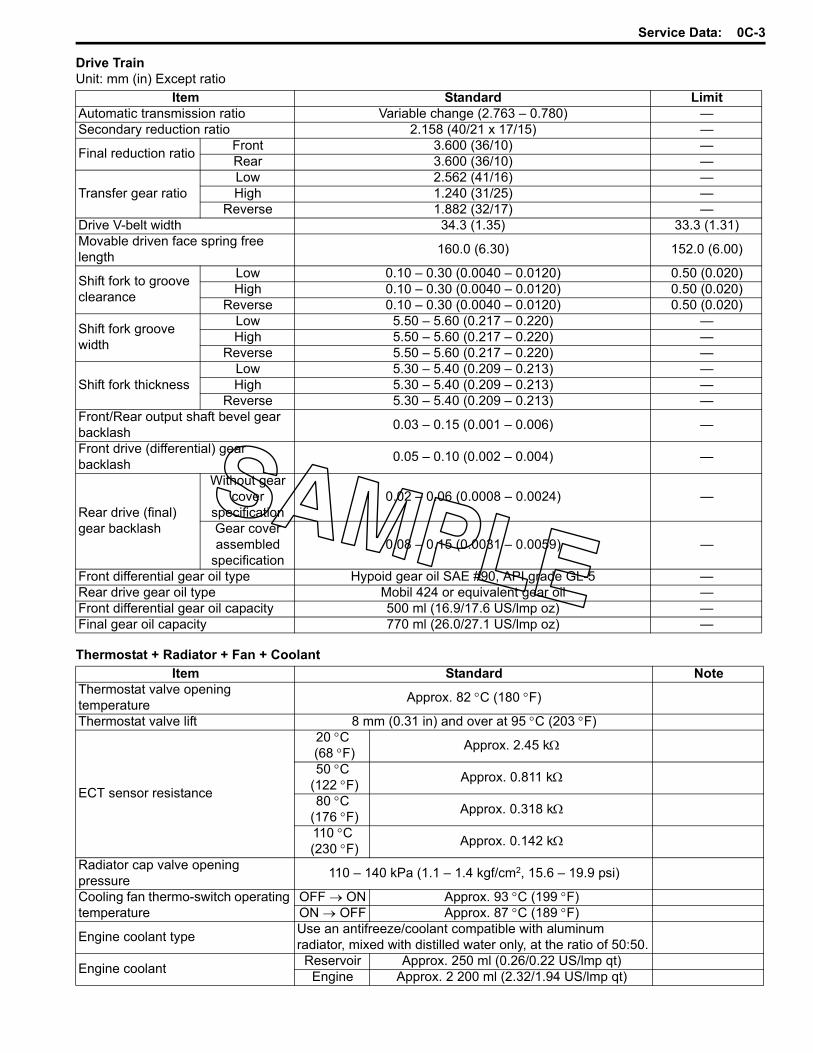
Drive TrainUnit: mm (in) Except ratio
Thermostat + Radiator + Fan + Coolant
Item Standard LimitAutomatic transmission ratio Variable change (2.763 – 0.780) —Secondary reduction ratio 2.158 (40/21 x 17/15) —
Final reduction ratio Front 3.600 (36/10) —Rear 3.600 (36/10) —
Transfer gear ratioLow 2.562 (41/16) —High 1.240 (31/25) —
Reverse 1.882 (32/17) —Drive V-belt width 34.3 (1.35) 33.3 (1.31)Movable driven face spring free length 160.0 (6.30) 152.0 (6.00)
Shift fork to groove clearance
Low 0.10 – 0.30 (0.0040 – 0.0120) 0.50 (0.020)High 0.10 – 0.30 (0.0040 – 0.0120) 0.50 (0.020)
Reverse 0.10 – 0.30 (0.0040 – 0.0120) 0.50 (0.020)
Shift fork groove width
Low 5.50 – 5.60 (0.217 – 0.220) —High 5.50 – 5.60 (0.217 – 0.220) —
Reverse 5.50 – 5.60 (0.217 – 0.220) —
Shift fork thicknessLow 5.30 – 5.40 (0.209 – 0.213) —High 5.30 – 5.40 (0.209 – 0.213) —
Reverse 5.30 – 5.40 (0.209 – 0.213) —Front/Rear output shaft bevel gear backlash 0.03 – 0.15 (0.001 – 0.006) —
Front drive (differential) gear backlash 0.05 – 0.10 (0.002 – 0.004) —
Rear drive (final) gear backlash
Without gear cover
specification0.02 – 0.06 (0.0008 – 0.0024) —
Gear cover assembled
specification0.08 – 0.15 (0.0031 – 0.0059) —
Front differential gear oil type Hypoid gear oil SAE #90, API grade GL-5 —Rear drive gear oil type Mobil 424 or equivalent gear oil —Front differential gear oil capacity 500 ml (16.9/17.6 US/lmp oz) —Final gear oil capacity 770 ml (26.0/27.1 US/lmp oz) —
Item Standard NoteThermostat valve opening temperature Approx. 82 °C (180 °F)
Thermostat valve lift 8 mm (0.31 in) and over at 95 °C (203 °F)
ECT sensor resistance
20 °C (68 °F) Approx. 2.45 kΩ
50 °C (122 °F) Approx. 0.811 kΩ
80 °C (176 °F) Approx. 0.318 kΩ
110 °C (230 °F) Approx. 0.142 kΩ
Radiator cap valve opening pressure 110 – 140 kPa (1.1 – 1.4 kgf/cm2, 15.6 – 19.9 psi)
Cooling fan thermo-switch operating temperature
OFF → ON Approx. 93 °C (199 °F)ON → OFF Approx. 87 °C (189 °F)
Engine coolant type Use an antifreeze/coolant compatible with aluminum radiator, mixed with distilled water only, at the ratio of 50:50.
Engine coolant Reservoir Approx. 250 ml (0.26/0.22 US/lmp qt)Engine Approx. 2 200 ml (2.32/1.94 US/lmp qt)

0C-4 Service Data:
Injector + Fuel Pump + Fuel Pressure Regulator
FI Sensors + Secondary Throttle Valve Actuator
Throttle Body
Item Specification NoteInjector resistance 11 – 13 Ω at 20 °C (68 °F)Fuel pump discharge amount 55.5 ml (1.88/1.95 US/lmp qt) and more/10 sec.Fuel pressure regulator operating set pressure Approx. 294 kPa (2.9 kgf/cm2, 41 psi)
Item Specification NoteCKP sensor resistance 150 – 250 ΩCKP sensor peak voltage 5.0 V and more When crankingIAP sensor input voltage 4.5 – 5.5 VIAP sensor output voltage Approx. 2.63 V at idle speedTP sensor input voltage 4.5 – 5.5 V
TP sensor output voltage Closed Approx. 1.1 VOpened Approx. 4.3 V
ECT sensor input voltage 4.5 – 5.5 VECT sensor output voltage 0.15 – 4.85 VECT sensor resistance Approx. 2.45 kΩ at 20 °C (68 °F)IAT sensor input voltage 4.5 – 5.5 VIAT sensor output voltage 0.15 – 4.85 VIAT sensor resistance Approx. 1.60 kΩ at 20 °C (68 °F)TO sensor resistance 19 – 20 kΩ
TO sensor voltage Normal 0.4 – 1.4 VLeaning 3.7 – 4.4 V When leaning 65°
GP switch voltage 0.6 V and more From 1st to TopInjector voltage Battery voltageIgnition coil primary peak voltage 80 V and more When crankingISC valve resistance Approx. 31 kΩ at 20 °C (68 °F)
Item SpecificationBore size 42 mmI.D. No. 31G0Idle r/min 1 300 ± 100 r/minFast idle r/min 1 500 – 2 000 r/min (When cold engine)Throttle cable play 3 – 5 mm (0.12 – 0.20 in)

Service Data: 0C-5
ElectricalUnit: mm (in)
WattageUnit: W
Item Specification Note
Spark plug Type NGK: CR6EDENSO: U20ESR-N
Gap 0.7 – 0.8 (0.028 – 0.031)Spark performance Over 8 (0.3) at 1 atm.CKP sensor resistance 150 – 250 ΩCKP sensor peak voltage 5.0 V and more
Ignition coil resistancePrimary 0.1 – 0.6 Ω Terminal –
Ground
Secondary 12 – 19 kΩ Plug cap – Terminal
Ignition coil primary peak voltage 80 V and more When crankingGenerator coil resistance 0.4 – 1.0 ΩGenerator maximum output Approx. 400 W at 5 000 r/minGenerator no-load voltage(When engine is cold) 75 V (AC) and more at 5 000 r/min
Regulated voltage 13.5 – 15.5 V at 5 000 r/min
Starter motor brush length Standard 12.0 (0.47)Limit 6.5 (0.26)
Starter torque limiter slip torque Standard 41.2 – 62.8 N⋅m (4.2 – 6.4 kgf-m, 14.5 – 32.5 lbf-ft)
Starter relay resistance 3 – 5 Ω
BatteryType
designation YTX20CH-BS
Capacity 12 V 64.8 kC (18 Ah)/10 HR
Fuse size
Headlight HI 10 ALO 10 A
Power source 10 AIgnition 15 A
Fuel 10 AFan 15 AMain 30 AEPS 40 A
Item SpecificationP-24, 28, 33 P-17
Headlight HI 35 x 2 ←LO 35 x 2 ←
Auxiliary headlight 35/35 ←Brake light/Taillight 21/5 ←Reversing light — 21Speedometer light LED ←High beam indicator light — LEDNeutral indicator light LED ←FI indicator light/Engine coolant temp. indicator light LED ←
Reverse indicator light LED ←Differential lock indicator light LED ←EPS indicator light LED ←

0C-6 Service Data:
Brake + WheelUnit: mm (in)
TireUnit: mm (in)
SuspensionUnit: mm (in)
Fuel + Oil
Item Standard/Specification LimitRear brake pedal height 12.5 – 22.5 (0.5 – 0.9) —Rear brake pedal free travel 20 – 30 (0.8 – 1.2) —Front brake disc thickness — 3.0 (0.20)Front brake disc runout — 0.30 (0.012)Front master cylinder bore 12.700 – 12.743 (0.5000 – 0.5017) —Front master cylinder piston diam. 12.657 – 12.684 (0.4983 – 0.4994) —Front brake caliper cylinder bore 33.960 – 34.010 (1.3370 – 1.3390) —Front brake caliper piston diam. 33.878 – 33.928 (1.3338 – 1.3357) —Rear brake lever play 6 – 8 (0.2 – 0.3) —Brake fluid type DOT 4 —Steering angle 46° (right & left) —Turning radius 3.1 m (10.2 ft) —Toe-out (With 75 kg, 165 lbs) 5 ± 4 mm (0.20 ± 0.16) —Camber –1.3° —Caster 3.3° —
Item Standard LimitCold inflation tire pressure(Solo riding)
Front 35 kPa (0.35 kgf/cm2, 5.1 psi) —Rear 30 kPa (0.30 kgf/cm2, 4.4 psi) —
Tire size Front AT25 x 8-12 , tubeless —Rear AT25 x 10-12 , tubeless —
Tire tread depth Front — 4.0 (0.16)Rear — 4.0 (0.16)
Item Standard LimitFront shock absorber spring adjustor 2/5 position —
Rear shock absorber spring adjustor 2/5 position —
Item Specification Note
Fuel type
Use only unleaded gasoline of at least 87 pump octane (R/2 + M/2) or 91 octane or higher rated by the Research Method. Gasoline containing MTBE (Methyl Tertiary Butyl Ether), less than 10% ethanol, or less than 5% methanol with appropriate cosolvents and corrosion inhibitor is permissible.
P-28, 33
Gasoline used should be graded 91 octane or higher. An unleaded gasoline type is recommended. Others
Fuel tank capacity 17.5 L (4.6/3.8 US/lmp gal)Engine oil type SAE 10 W-40, API SF/SG or SH/SJ with JASO MA
Engine oil capacityChange 2 300 ml (2.4/2.0 US/lmp qt)
Filter change 2 500 ml (2.6/2.2 US/lmp qt)Overhaul 3 000 ml (3.2/2.6 US/lmp qt)

Service Data: 0C-7
Tightening Torque List (LT-A750XP/ZK9)B931G30307004
EngineItem N⋅m kgf-m lbf-ft
Spark plug 11 1.1 8.0
Cylinder head cover bolt Initial 10 1.0 7.0Final 14 1.4 10.5
Cam drive idle gear/sprocket shaft 41 4.1 29.5Intake pipe bolt 9 0.9 6.5Cylinder head bolt (M6) 10 1.0 7.0
Cylinder head bolt (L200) Initial 25 2.5 18.0Final 37 3.7 27.0
Cylinder head bolt (L: 70) 10 1.0 7.0Cylinder head bolt (L: 100) 10 1.0 7.0Camshaft journal holder bolt 10 1.0 7.0Cam chain tension adjuster bolt 10 1.0 7.0Cam chain tension adjuster cap bolt 7 0.7 5.0Crankcase bolt (M6) 10 1.0 7.0Crankcase bolt (M8) 26 2.6 19.0Valve timing inspection plug 23 2.3 16.5Clutch shoe nut 150 15.0 108.5Movable drive face bolt 110 11.0 79.5Movable driven face bolt 110 11.0 79.5Movable driven face ring nut 110 11.0 79.5V-belt outer cover bolt 8 0.8 6.0V-belt inner cover bolt 9 0.9 6.5Generator rotor nut 160 16.0 115.5Generator stator set bolt 11 1.1 8.0Speed sensor bolt 10 1.0 7.0Starter clutch bolt 26 2.6 19.0Exhaust pipe nut 23 2.3 16.5Muffler connecting bolt 23 2.3 16.5Muffler mounting bolt 23 2.3 16.5Engine oil drain plug 21 2.1 15.0Engine coolant drain plug 13 1.3 9.5Drive bevel gear nut 100 10.0 72.5Front output shaft nut 100 10.0 72.5Engine mounting nut 60 6.0 43.5Engine mounting damper stopper bolt 23 2.3 16.5Rear output shaft nut 100 10.0 72.5Crank balancer drive gear nut 150 15.0 108.5Crank balancer driven gear bolt 50 5.0 36.0Starter motor mounting bolt 10 1.0 7.0Starter motor lead wire connecting nut 6 0.6 4.5Starter motor housing bolt 5 0.5 3.5Main oil gallery plug 18 1.8 13.0Air cleaner box mounting bolt 4.5 0.45 3.0Left crankshaft spacer nut 38 3.8 27.5Oil gallery plug (Cylinder head) 10 1.0 7.0

0C-8 Service Data:
Drive Train
FI System, Intake Air System and Fuel System
Cooling System
Item N⋅m kgf-m lbf-ft4WD/Diff-lock actuator mounting bolt 22 2.2 16.0Front drive (Differential) gear case bolt 22 2.2 16.0Front drive (Differential) gear case mounting nut 50 5.0 36.0Front drive (Differential) gear oil level plug 8.5 0.85 6.0Front drive (Differential) gear oil filler plug 35 3.5 25.5Front drive (Differential) gear oil drain plug 32 3.2 23.0Final drive gear nut 100 10.0 72.5Final drive gear bearing stopper 100 10.0 72.5Final gear case bolt (M8) 26 2.6 19.0Final gear case bolt (M10) 55 5.5 40.0Final gear mounting nut 65 6.5 47.0Final gear mounting bolt 65 6.5 47.0Rear propeller shaft boot clamp screw 2 0.2 1.5Final gear oil drain plug 23 2.3 16.5Rear propeller shaft coupling nut 100 10.0 72.5Front output shaft bolt 10 1.0 7.0Rear output shaft nut 100 10.0 72.5Rear output shaft drive bevel gear nut 100 10.0 72.5Rear output shaft driven gear nut 100 10.0 72.5Front propeller shaft boot clamp screw 1.3 0.13 1.0Rear propeller shaft boot clamp screw 2 0.2 1.5
Item N⋅m kgf-m lbf-ftCKP sensor mounting bolt 6 0.6 4.5CKP sensor bracket bolt 6 0.6 4.5Fuel delivery pipe mounting screw 5 0.5 3.5Fuel pump retainer 35 3.5 25.5ECT sensor 18 1.8 13.0ISC valve mounting screw 2 0.2 1.5TP sensor mounting screw 2 0.2 1.5
Item N⋅m kgf-m lbf-ftWater pump cover screw 6 0.6 4.5Water pump mounting bolt 10 1.0 7.0Cooling fan thermo-switch 17 1.7 12.5Thermostat cover bolt 23 2.3 16.5Cooling fan assembly mounting bolt 8.5 0.85 6.0Water bypass union 12 1.2 8.5

Service Data: 0C-9
ChassisItem N⋅m kgf-m lbf-ft
Handlebar clamp bolt 26 2.6 19.0Handlebar holder nut 60 6.0 43.5Rear brake lever holder clamp bolt 10 1.0 7.0Throttle lever case bolt 2 0.2 1.5Steering shaft upper nut 120 12.0 87.0Steering shaft bolt 26 2.6 19.0EPS control unit mounting nut 12 1.2 8.5EPS body assembly mounting bolt 26 2.6 19.0EPS body assembly mounting nut 28 2.8 20.0Steering shaft lower nut 162 16.2 117.0Front suspension arm pivot nut (Upper) 60 6.0 43.5Front suspension arm pivot nut (Lower) 65 6.5 47.0Steering knuckle end nut (Upper and Lower) 29 2.9 21.0Tie-rod end nut 29 2.9 21.0Tie-rod lock-nut 29 2.9 21.0Front shock absorber mounting bolt (Upper) 55 5.5 40.0Front shock absorber mounting nut (Lower) 60 6.0 43.5Front wheel hub nut 110 11.0 79.5Rear wheel hub nut 121 12.1 87.5Wheel set nut (Front and Rear) 60 6.0 43.5Front brake hose union bolt 23 2.3 16.5Front brake air bleeder valve 6 0.6 4.5Front brake pad mounting pin 17 1.7 12.5Front brake caliper mounting bolt 26 2.6 19.0Caliper holder pin 18 1.8 13.0Caliper holder slide pin 23 2.3 16.5Brake pipe flare nut 16 1.6 11.5Front brake disc mounting bolt 23 2.3 16.5Brake master cylinder mounting bolt 10 1.0 7.0Footrest mounting bolt (M8) 26 2.6 19.0Footrest mounting bolt (M10) 55 5.5 40.0Rear stabilizer joint nut 60 6.0 43.5Rear shock absorber mounting nut (Upper and Lower) 60 6.0 43.5Rear suspension arm pivot nut (Upper and Lower) 60 6.0 43.5Rear knuckle end nut (Upper and Lower) 60 6.0 43.5Rear brake cam lever nut 11 1.1 8.0Rear brake case bolt 26 2.6 19.0Rear brake pedal shaft nut 60 6.0 43.5Rear brake pedal screw 4.5 0.45 3.0Trailer towing bolt 60 6.0 43.5Brake lever pivot bolt and nut 6 0.6 4.5Brake lever pivot bolt lock-nut 6 0.6 4.5Front propeller shaft boot clamp screw 1.3 0.13 1.0Rear propeller shaft boot clamp screw 2 0.2 1.5

0C-10 Service Data:
Tightening Torque ChartFor other bolts and nuts not listed in the preceding page, refer to this chart:
Bolt Diameter “a” (mm)
Conventional or “4” marked bolt “7” marked boltN⋅m kgf-m lbf-ft N⋅m kgf-m lbf-ft
4 1.5 0.15 1.0 2.3 0.23 1.55 3 0.3 2.0 4.5 0.45 3.06 5.5 0.55 4.0 10 1.0 7.08 13 1.3 9.5 23 2.3 16.510 29 2.9 21.0 50 5.0 36.012 45 4.5 32.5 85 8.5 61.514 65 6.5 47.0 135 13.5 97.516 105 10.5 76.0 210 21.0 152.018 160 16.0 115.5 240 24.0 173.5
321
“a” “a” “a”
I649G1030001-04
1. Conventional bolt 2. “4” marked bolt 3. “7” marked bolt

Table of Contents 1- i
1
Section 1
CONTENTS
Engine
NOTEFor the items with asterisk (*) in the “CONTENTS” below, refer to the same section of the service manual mentioned in the “FOREWORD” of this manual.
Precautions ................................................. 1-*Precautions..............................................................1-*
Precautions for Engine...........................................1-*
Engine General Information and Diagnosis ..................................................1A-*
General Description ............................................. 1A-*Injection Timing Description.................................1A-*
Schematic and Routing Diagram........................ 1A-*FI System Wiring Diagram ...................................1A-*Terminal Alignment of ECM Coupler....................1A-*
Component Location ........................................... 1A-*FI System Parts Location.....................................1A-*
Diagnostic Information and Procedures............ 1A-*Engine Symptom Diagnosis .................................1A-*Self-Diagnostic Procedures .................................1A-*Use of SDS Diagnosis Reset Procedures............1A-*Show Data When Trouble (Displaying Data at
the Time of DTC) ...............................................1A-*SDS Check ..........................................................1A-*DTC Table............................................................1A-*Fail-Safe Function Table ......................................1A-*FI System Troubleshooting ..................................1A-*Malfunction Code and Defective Condition
Table ..................................................................1A-*DTC “C12” (P0335): CKP Sensor Circuit
Malfunction.........................................................1A-*DTC “C13” (P0105-H/L): IAP Sensor Circuit
Malfunction.........................................................1A-*DTC “C14” (P0120-H/L): TP Sensor Circuit
Malfunction.........................................................1A-*DTC “C15” (P0115-H/L): ECT Sensor Circuit
Malfunction.........................................................1A-*DTC “C20” (P1752): Diff-lock Relay Circuit
Malfunction.........................................................1A-*DTC “C21” (P0110-H/L): IAT Sensor Circuit
Malfunction.........................................................1A-*DTC “C23” (P1651-H/L): TO Sensor Circuit
Malfunction.........................................................1A-*DTC “C24” (P0351): Ignition Coil Circuit
Malfunction.........................................................1A-*DTC “C32” (P0201): Fuel Injector Circuit
Malfunction.........................................................1A-*
DTC “C40” (P05057): ISC Valve Circuit Malfunction........................................................ 1A-*
DTC “C41” (P230-H/L): FP Relay Circuit Malfunction........................................................ 1A-*
Specifications....................................................... 1A-*Service Data........................................................ 1A-*
Special Tools and Equipment ............................. 1A-*Special Tool ........................................................ 1A-*
Emission Control Devices .......................1B-*Precautions........................................................... 1B-*
Precautions for Emission Control Devices .......... 1B-*Repair Instructions .............................................. 1B-*
Crankcase Breather (PCV) Hose Inspection....... 1B-*Crankcase Breather (PCV) Hose Removal
and Installation .................................................. 1B-*
Engine Electrical Devices ........................1C-*Precautions........................................................... 1C-*
Precautions for Engine Electrical Device ............ 1C-*Component Location ........................................... 1C-*
Engine Electrical Components Location ............. 1C-*Diagnostic Information and Procedures............ 1C-*
Engine Symptom Diagnosis ................................ 1C-*Repair Instructions .............................................. 1C-*
ECM Removal and Installation............................ 1C-*CKP Sensor Inspection ....................................... 1C-*CKP Sensor Removal and Installation ................ 1C-*IAP Sensor Inspection......................................... 1C-*IAP Sensor Removal and Installation.................. 1C-*TP Sensor Inspection.......................................... 1C-*TP Sensor Removal and Installation................... 1C-*TP Sensor Adjustment ........................................ 1C-*IAT Sensor Inspection......................................... 1C-*IAT Sensor Removal and Installation.................. 1C-*ECT Sensor Removal and Installation ................ 1C-*ECT Sensor Inspection ....................................... 1C-*TO Sensor Inspection ......................................... 1C-*TO Sensor Removal and Installation .................. 1C-*ISC Valve Inspection........................................... 1C-*ISC Valve Removal and Installation.................... 1C-*GP Switch Inspection .......................................... 1C-*GP Switch Removal and Installation ................... 1C-*

1-ii Table of Contents
Specifications....................................................... 1C-*Service Data........................................................ 1C-*Tightening Torque Specifications........................ 1C-*
Special Tools and Equipment ............................. 1C-*Recommended Service Material ......................... 1C-*Special Tool ........................................................ 1C-*
Engine Mechanical ................................... 1D-*Schematic and Routing Diagram........................ 1D-*
Throttle Cable Routing Diagram.......................... 1D-*Diagnostic Information and Procedures............ 1D-*
Engine Mechanical Symptom Diagnosis............. 1D-*Compression Pressure Check ............................ 1D-*
Repair Instructions .............................................. 1D-*Engine Components Removable with the
Engine in Place ................................................. 1D-*Air Cleaner Element Removal and Installation .... 1D-*Air Cleaner Element Inspection and Cleaning .... 1D-*Air Cleaner Box Removal and Installation........... 1D-*Throttle Cable Removal and Installation ............. 1D-*Throttle Cable Inspection .................................... 1D-*Throttle Cable Play Inspection and
Adjustment ........................................................ 1D-*Throttle Body Components ................................. 1D-*Throttle Body Construction.................................. 1D-*Throttle Body Removal and Installation .............. 1D-*Throttle Body Disassembly and Assembly.......... 1D-*Throttle Body Inspection and Cleaning ............... 1D-*Engine Assembly Removal ................................. 1D-*Engine Assembly Installation .............................. 1D-*Engine Top Side Disassembly ............................ 1D-*Engine Top Side Assembly ................................. 1D-*Valve Clearance Inspection and Adjustment ...... 1D-*Camshaft Inspection ........................................... 1D-*Camshaft Sprocket Inspection ............................ 1D-*Cam Chain Tension Adjuster Inspection............. 1D-*Cam Chain Guide Removal and Installation ....... 1D-*Cam Chain Guide Inspection .............................. 1D-*Cam Chain Tensioner Inspection........................ 1D-*Cylinder Head Disassembly and Assembly ........ 1D-*Cylinder Head Related Parts Inspection ............. 1D-*Valve Guide Replacement .................................. 1D-*Valve Seat Repair ............................................... 1D-*Cam Drive Idle Gear / Sprocket Thrust
Clearance Inspection and Adjustment .............. 1D-*Cylinder Disassembly and Assembly .................. 1D-*Cylinder Inspection.............................................. 1D-*Piston Ring Removal and Installation ................. 1D-*Piston and Piston Ring Inspection ...................... 1D-*Engine Bottom Side Disassembly ....................... 1D-*Engine Bottom Side Assembly............................ 1D-*Conrod and Crankshaft Inspection...................... 1D-*Width Between Crankshaft Webs ....................... 1D-*Crankshaft Oil Seal Inspection............................ 1D-*Bearing Inspection .............................................. 1D-*Bearing Removal and Installation ....................... 1D-*
Specifications....................................................... 1D-*Service Data........................................................ 1D-*Tightening Torque Specifications........................ 1D-*
Special Tools and Equipment ............................. 1D-*Recommended Service Material ......................... 1D-*Special Tool ........................................................ 1D-*
Engine Lubrication System ..................... 1E-*Precautions........................................................... 1E-*
Precautions for Engine Oil .................................. 1E-*Schematic and Routing Diagram........................ 1E-*
Engine Lubrication System Chart Diagram ......... 1E-*Diagnostic Information and Procedures............ 1E-*
Engine Lubrication Symptom Diagnosis ............. 1E-*Oil Pressure Check ............................................. 1E-*
Repair Instructions .............................................. 1E-*Engine Oil and Filter Replacement ..................... 1E-*Engine Oil Level Inspection................................. 1E-*Oil Sump Filter Removal and Installation ............ 1E-*Oil Sump Filter Inspection and Cleaning............. 1E-*Oil Jet Removal and Installation.......................... 1E-*Oil Jet Inspection................................................. 1E-*Oil Pump Removal and Installation ..................... 1E-*Oil Pump Inspection ............................................ 1E-*
Specifications....................................................... 1E-*Service Data........................................................ 1E-*Tightening Torque Specifications........................ 1E-*
Special Tools and Equipment ............................. 1E-*Recommended Service Material ......................... 1E-*Special Tool ........................................................ 1E-*
Engine Cooling System ........................... 1F-*Precautions............................................................1F-*
Precautions for Engine Cooling System...............1F-*Precautions for Engine Coolant ...........................1F-*
General Description ..............................................1F-*Engine Coolant Description..................................1F-*
Schematic and Routing Diagram.........................1F-*Cooling Circuit Diagram .......................................1F-*Water Hose Routing Diagram ..............................1F-*
Diagnostic Information and Procedures.............1F-*Engine Cooling Symptom Diagnosis....................1F-*
Repair Instructions ...............................................1F-*Cooling Circuit Inspection ....................................1F-*Radiator Cap Inspection.......................................1F-*Radiator Inspection and Cleaning ........................1F-*Cooling Fan Assembly / Radiator Removal
and Installation ...................................................1F-*Water Hose Removal and Installation..................1F-*Cooling Fan Inspection ........................................1F-*Radiator Reservoir Tank Removal and
Installation ..........................................................1F-*Radiator Reservoir Tank Inspection.....................1F-*Water Hose Inspection.........................................1F-*ECT Sensor Removal and Installation .................1F-*ECT Sensor Inspection ........................................1F-*Cooling Fan Thermo-switch Removal and
Installation ..........................................................1F-*Cooling Fan Thermo-switch Inspection................1F-*Thermostat Removal and Installation...................1F-*Thermostat Inspection..........................................1F-*Water Pump Components....................................1F-*

Table of Contents 1-iii
Water Pump Removal and Installation.................1F-*Water Pump Disassembly and Assembly ............1F-*Water Pump Related Parts Inspection.................1F-*
Specifications........................................................1F-*Service Data ........................................................1F-*Tightening Torque Specifications.........................1F-*
Special Tools and Equipment ..............................1F-*Recommended Service Material ..........................1F-*Special Tool .........................................................1F-*
Fuel System ..............................................1G-*Precautions........................................................... 1G-*
Precautions for Fuel System............................... 1G-*General Description ............................................. 1G-*
Fuel System Description ..................................... 1G-*Schematic and Routing Diagram........................ 1G-*
Fuel Hose Routing Diagram................................ 1G-*Fuel Tank Breather Hose Routing Diagram........ 1G-*
Diagnostic Information and Procedures............ 1G-*Fuel System Diagnosis ....................................... 1G-*
Repair Instructions .............................................. 1G-*Fuel Pressure Inspection .................................... 1G-*Fuel Pump Inspection ......................................... 1G-*Fuel Discharge Amount Inspection ..................... 1G-*Fuel Pump Relay Inspection ............................... 1G-*Fuel Hose Inspection .......................................... 1G-*Fuel Feed Hose Removal and Installation .......... 1G-*Fuel Level Gauge Inspection .............................. 1G-*Fuel Level Indicator Inspection ........................... 1G-*Fuel Tank Removal and Installation.................... 1G-*Fuel Pump Components ..................................... 1G-*Fuel Pump Assembly Removal and
Installation......................................................... 1G-*Fuel Pump Disassembly and Assembly.............. 1G-*Fuel Mesh Filter Inspection and Cleaning........... 1G-*Fuel Injector Inspection and Cleaning................. 1G-*Fuel Injector / Fuel Delivery Pipe Removal
and Installation.................................................. 1G-*Fuel Tank Pressure Control (FTPC) Valve
Removal and Installation................................... 1G-*Fuel Tank Pressure Control (FTPC) Valve
Inspection.......................................................... 1G-*Specifications....................................................... 1G-*
Service Data ....................................................... 1G-*Tightening Torque Specifications........................ 1G-*
Special Tools and Equipment ............................. 1G-*Special Tool ........................................................ 1G-*
Ignition System.........................................1H-*General Description ............................................. 1H-*
Override Switch Description................................ 1H-*Schematic and Routing Diagram........................ 1H-*
Ignition System Diagram..................................... 1H-*Ignition System Components Location ............... 1H-*
Diagnostic Information and Procedures............ 1H-*Ignition System Symptom Diagnosis................... 1H-*No Spark or Poor Spark...................................... 1H-*
Repair Instructions .............................................. 1H-*Spark Plug Cap and Spark Plug Removal and
Installation ......................................................... 1H-*Spark Plug Inspection and Cleaning ................... 1H-*Ignition Coil and Plug Cap Inspection ................. 1H-*CKP Sensor Inspection ....................................... 1H-*CKP Sensor Removal and Installation ................ 1H-*Engine Stop Switch Inspection............................ 1H-*Ignition Switch Inspection.................................... 1H-*Ignition Switch Removal and Installation............. 1H-*Override Switch Inspection ................................. 1H-*
Specifications....................................................... 1H-*Service Data........................................................ 1H-*Tightening Torque Specifications........................ 1H-*
Special Tools and Equipment ............................. 1H-*Special Tool ........................................................ 1H-*
Starting System .........................................1I-1Schematic and Routing Diagram..........................1I-*
Starting System Diagram ......................................1I-*Component Location .............................................1I-*
Starting System Components Location.................1I-*Diagnostic Information and Procedures..............1I-*
Starting System Symptom Diagnosis....................1I-*Starter Motor will not Run......................................1I-*Starter Motor Runs but Does not Crank the
Engine.................................................................1I-*Engine Does not Turn Though the Starter
Motor Runs..........................................................1I-*Repair Instructions ............................................... 1I-1
Starter Motor Components....................................1I-*Starter Motor Removal and Installation.................1I-*Starter Motor Disassembly and Assembly ............1I-*Starter Motor Inspection........................................1I-*Starter Relay Removal and Installation.................1I-*Starter Relay Inspection........................................1I-*Neutral Relay Removal and Installation ................1I-*Neutral Relay Inspection .......................................1I-*Neutral Relay Diode Inspection.............................1I-*Parking Brake Relay Removal and Installation ......1I-*Parking Brake Relay Inspection ............................1I-*Parking Brake Switch Inspection...........................1I-*Gear Position Switch Inspection ...........................1I-*Starter Torque Limiter / Starter Clutch
Removal and Installation.....................................1I-*Starter Driven Gear Bearing Removal and
Installation ...........................................................1I-*Starter Related Parts Inspection ...........................1I-*Starter Button Inspection.......................................1I-*Recoil Starter Components ...................................1I-*Recoil Starter Assembly Removal and
Installation ...........................................................1I-*Recoil Starter Disassembly and Assembly ...........1I-*Recoil Starter Inspection .......................................1I-*Starter Motor Components (LT-A750XP/ZK9) ..... 1I-1Starter Motor Removal and Installation (LT-
A750XP/ZK9) ..................................................... 1I-2Starter Motor Disassembly and Assembly
(LT-A750XP/ZK9)............................................... 1I-2

1-iv Table of Contents
Starter Motor Related Parts Inspection (LT-A750XP/ZK9) ..................................................... 1I-3
Specifications........................................................ 1I-5Service Data..........................................................1I-*Service Data (LT-A750XP/ZK9) ........................... 1I-5Tightening Torque Specifications......................... 1I-5
Special Tools and Equipment .............................. 1I-5Recommended Service Material .......................... 1I-5Special Tool ......................................................... 1I-5
Charging System......................................1J-1Schematic and Routing Diagram.........................1J-*
Charging System Diagram................................... 1J-*Component Location ............................................1J-*
Charging System Components Location.............. 1J-*Diagnostic Information and Procedures.............1J-*
Charging System Symptom Diagnosis................. 1J-*Battery Runs Down Quickly ................................. 1J-*
Repair Instructions .............................................. 1J-1Battery Current Leakage Inspection..................... 1J-*Regulated Voltage Inspection .............................. 1J-*Generator Inspection............................................ 1J-*Generator Removal and Installation..................... 1J-*Regulator / Rectifier Inspection ............................ 1J-*Battery Components ............................................ 1J-*
Battery Charging .................................................. 1J-*Battery Removal and Installation ......................... 1J-*Battery Visual Inspection...................................... 1J-*Generator Removal and Installation (LT-
A750XP/ZK9) .................................................... 1J-1Battery Removal and Installation (LT-
A750XP/ZK9) .................................................... 1J-2Specifications....................................................... 1J-3
Service Data......................................................... 1J-*Tightening Torque Specifications........................ 1J-3
Special Tools and Equipment ............................. 1J-3Recommended Service Material ......................... 1J-3Special Tool ........................................................ 1J-3
Exhaust System........................................1K-*Precautions........................................................... 1K-*
Precautions for Exhaust System ......................... 1K-*Repair Instructions .............................................. 1K-*
Exhaust System Construction ............................. 1K-*Exhaust Pipe / Muffler Removal and
Installation ......................................................... 1K-*Exhaust System Inspection................................. 1K-*Spark Arrester Inspection.................................... 1K-*
Specifications....................................................... 1K-*Tightening Torque Specifications........................ 1K-*

Starting System: 1I-1
EngineStarting SystemRepair Instructions
Starter Motor Components (LT-A750XP/ZK9)B931G31906022
1
2
5
6
3
4
5
7
(a)
(b)
(c)
(d)
FWDFWD
I931G3190012-03
1. O-ring 6. Starter motor case : 5 N⋅m (0.5 kgf-m, 3.5 lbf-ft)2. Housing end (Inside) 7. Housing end (Outside) : Apply grease to sliding surface.3. O-ring : 6 N⋅m (0.6 kgf-m, 4.5 lbf-ft) : Apply moly paste to sliding surface.4. Armature : 11 N⋅m (1.1 kgf-m, 8.0 lbf-ft) : Do not reuse.5. Square-ring : 10 N⋅m (1.0 kgf-m, 7.0 lbf-ft)

1I-2 Starting System:
Starter Motor Removal and Installation (LT-A750XP/ZK9)
B931G31906023
Removal1) Turn the ignition switch OFF and disconnect the
battery (–) lead wire. Refer to “Battery Removal and Installation (LT-A750XP/ZK9) in Section 1J (Page 1J-2)”.
2) Remove the right side cover. Refer to“Front Side Exterior Parts Removal and Installation in Section 9D in related manual”.
3) Remove the starter motor lead wire (1).
4) Remove the starter motor.
InstallationInstall the starter motor in the reverse order of removal. Pay attention to the following points:• Apply grease to the starter motor O-ring.
: Grease 99000–25010 (SUZUKI SUPER GREASE “A” or equivalent)
CAUTION!
Replace the O-ring with a new one.
• Tighten the starter motor mounting bolts (1) with the battery (–) lead wire (2) and starter motor lead wire mounting nut (3) to the specified torque. Refer to “Wiring Harness Routing Diagram (LT-A750XP/ZK9) in Section 9A (Page 9A-4)”.
Tightening torqueStarter motor mounting bolt (a): 10 N·m (1.0 kgf-m, 7.0 lbf-ft)Starter motor lead wire mounting nut (b): 6 N·m (0.6 kgf-m, 4.5 lbf-ft)
Starter Motor Disassembly and Assembly (LT-A750XP/ZK9)
B931G31906024Refer to “Starter Motor Removal and Installation in related manual”.
DisassemblyDisassemble the starter motor as shown in the starter motor components diagram. Refer to “Starter Motor Components in related manual”.
AssemblyReassemble the starter motor in the reverse order of removal. Pay attention to the following points:
CAUTION!
Replace the O-rings with new ones to prevent oil leakage and moisture.
• Apply grease to the lip of the oil seal.
: Grease 99000–25010 (SUZUKI SUPER GREASE “A” or equivalent)
1
I931G3190001-02
I931G3190002-02
(a)1
(b)3
2
I931G3190003-02
I931G3190004-02
Starting System: 1I-3
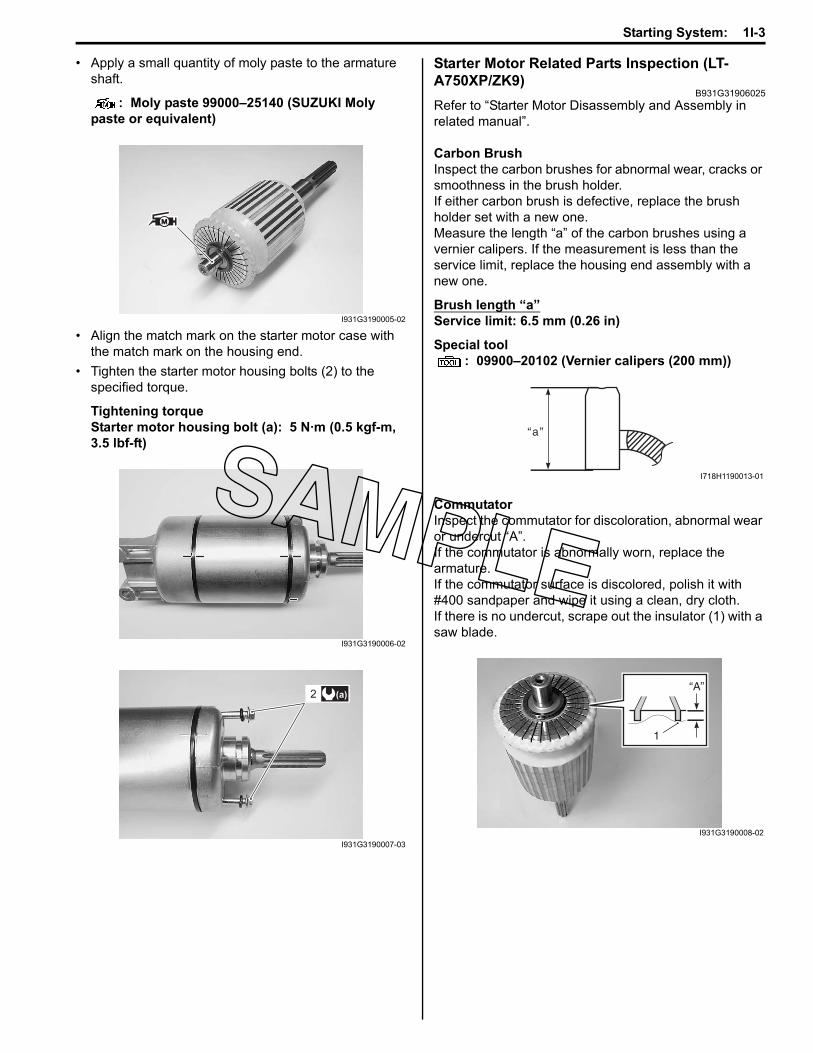
• Apply a small quantity of moly paste to the armature shaft.
: Moly paste 99000–25140 (SUZUKI Moly paste or equivalent)
• Align the match mark on the starter motor case with the match mark on the housing end.
• Tighten the starter motor housing bolts (2) to the specified torque.
Tightening torqueStarter motor housing bolt (a): 5 N·m (0.5 kgf-m, 3.5 lbf-ft)
Starter Motor Related Parts Inspection (LT-A750XP/ZK9)
B931G31906025Refer to “Starter Motor Disassembly and Assembly in related manual”.
Carbon BrushInspect the carbon brushes for abnormal wear, cracks or smoothness in the brush holder.If either carbon brush is defective, replace the brush holder set with a new one.Measure the length “a” of the carbon brushes using a vernier calipers. If the measurement is less than the service limit, replace the housing end assembly with a new one.
Brush length “a”Service limit: 6.5 mm (0.26 in)
Special tool: 09900–20102 (Vernier calipers (200 mm))
CommutatorInspect the commutator for discoloration, abnormal wear or undercut “A”.If the commutator is abnormally worn, replace the armature.If the commutator surface is discolored, polish it with #400 sandpaper and wipe it using a clean, dry cloth.If there is no undercut, scrape out the insulator (1) with a saw blade.
I931G3190005-02
I931G3190006-02
(a)2
I931G3190007-03
“a”
I718H1190013-01
“A”
1
I931G3190008-02
1I-4 Starting System:
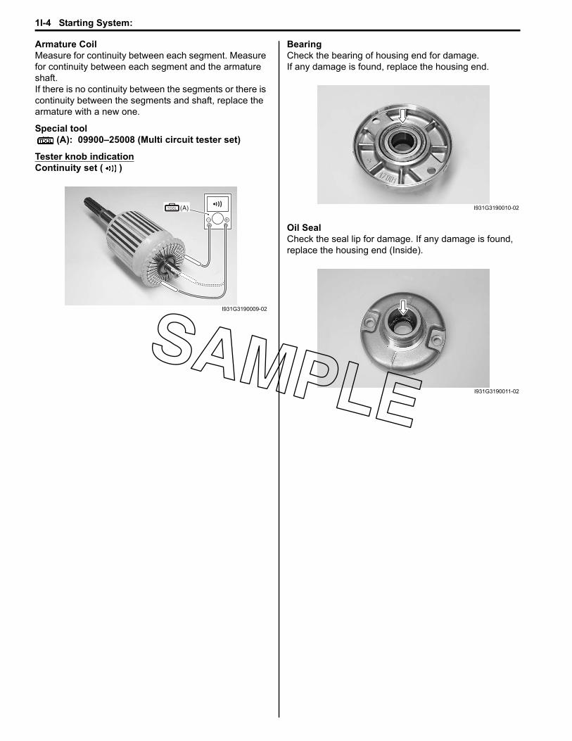
Armature CoilMeasure for continuity between each segment. Measure for continuity between each segment and the armature shaft.If there is no continuity between the segments or there is continuity between the segments and shaft, replace the armature with a new one.
Special tool(A): 09900–25008 (Multi circuit tester set)
Tester knob indicationContinuity set ( )
BearingCheck the bearing of housing end for damage.If any damage is found, replace the housing end.
Oil SealCheck the seal lip for damage. If any damage is found, replace the housing end (Inside).
(A)
I931G3190009-02
I931G3190010-02
I931G3190011-02

Starting System: 1I-5
SpecificationsService Data (LT-A750XP/ZK9)
B931G31907003Unit: mm (in)
Tightening Torque SpecificationsB931G31907004
NOTEThe specified tightening torque is described in the following.“Starter Motor Components (LT-A750XP/ZK9) (Page 1I-1)”
Reference:For the tightening torque of fastener not specified in this section, refer to “Tightening Torque List (LT-A750XP/ZK9) in Section 0C (Page 0C-7)”.
Special Tools and EquipmentRecommended Service Material
B931G31908001
NOTERequired service material is also described in the following.“Starter Motor Components (LT-A750XP/ZK9) (Page 1I-1)”
Special ToolB931G31908002
Item Specification Note
Starter motor brush length Standard 12.0 (0.47)Limit 6.5 (0.26)
Starter torque limiter slip torque Standard 41.2 – 62.8 N⋅m (4.2 – 6.4 kgf-m, 14.5 – 32.5 lbf-ft)
Starter relay resistance 3 – 5 Ω
Fastening part Tightening torque NoteN⋅m kgf-m lbf-ftStarter motor mounting bolt 10 1.0 7.0 (Page 1I-2)Starter motor lead wire mounting nut 6 0.6 4.5 (Page 1I-2)Starter motor housing bolt 5 0.5 3.5 (Page 1I-3)
Material SUZUKI recommended product or Specification NoteGrease SUZUKI SUPER GREASE “A” or
equivalentP/No.: 99000–25010 (Page 1I-2) / (Page 1I-2)
Moly paste SUZUKI Moly paste or equivalent P/No.: 99000–25140 (Page 1I-3)
09900–20102 09900–25008Vernier calipers (200 mm) Multi circuit tester set
(Page 1I-3) (Page 1I-4)

1J-1 Charging System:
EngineCharging SystemRepair Instructions
Generator Removal and Installation (LT-A750XP/ZK9)
B931G31A06010Removal1) Disconnect the (–) battery lead wire. Refer to
“Battery Removal and Installation (LT-A750XP/ZK9) (Page 1J-2)”.
2) Drain engine oil. Refer to “Engine Oil and Filter Replacement in Section 0B in related manual”.
3) Remove the left inner fender. Refer to “Front Side Exterior Parts Removal and Installation in Section 9D in related manual”.
4) Remove the left mud guard. Refer to “Rear Side Exterior Parts Removal and Installation in Section 9D in related manual”.
5) Drain engine coolant. Refer to “Cooling System Inspection in Section 0B in related manual”.
6) Remove the water pump assembly (1). Refer to “Water Pump Removal and Installation in Section 1F in related manual”.
7) Disconnect the gearshift lever arm (2) and speed sensor coupler (3).
8) Remove the recoil cover (4).
9) Disconnect the CKP sensor coupler (5) and generator coupler (6) and remove the clamp (7).
10) Hold the left crankshaft spacer (8) with the special tool.
Special tool(A): 09930–44530 (Rotor holder)
11) Remove the left crankshaft spacer nut (9) and spacer (8).
12) Remove the generator cover. Refer to “Generator Removal and Installation in related manual”.
InstallationInstall the generator in the reverse order of removal. Pay attention to the following points:• Install the generator cover. Refer to “Generator
Removal and Installation in related manual”.
WARNING!
Be careful not to pinch the finger between the generator cover and the crankcase.
• Apply grease to the O-ring (1) and oil seal lip.
: Grease 99000–25010 (SUZUKI SUPER GREASE “A” or equivalent)
CAUTION!
Replace the O-ring (1) with a new one.
2
4
1
3
I931G31A0001-01
67
5
I931G31A0008-01
9
(A)8
I931G31A0002-01
1
I931G31A0003-01
Charging System: 1J-2
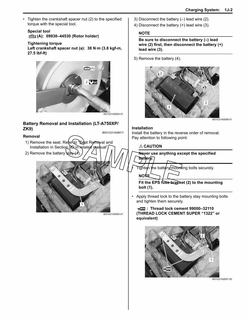
• Tighten the crankshaft spacer nut (2) to the specified torque with the special tool.
Special tool(A): 09930–44530 (Rotor holder)
Tightening torqueLeft crankshaft spacer nut (a): 38 N·m (3.8 kgf-m, 27.5 lbf-ft)
Battery Removal and Installation (LT-A750XP/ZK9)
B931G31A06011Removal1) Remove the seat. Refer to “Seat Removal and
Installation in Section 9D in related manual”.2) Remove the battery stay (1).
3) Disconnect the battery (–) lead wire (2).4) Disconnect the battery (+) lead wire (3).
NOTEBe sure to disconnect the battery (–) lead wire (2) first, then disconnect the battery (+) lead wire (3).
5) Remove the battery (4).
InstallationInstall the battery in the reverse order of removal.Pay attention to following point:
CAUTION!
Never use anything except the specified battery.
• Tighten the battery mounting bolts securely.
NOTEFit the EPS fuse bracket (2) to the mounting bolt (1).
• Apply thread lock to the battery stay mounting bolts and tighten them securely.
: Thread lock cement 99000–32110 (THREAD LOCK CEMENT SUPER “1322” or equivalent)
(A)
(a)2
I931G31A0004-01
1
I931G31A0005-01
2
4
3
I931G31A0006-01
1
2
I931G31A0007-02
1J-3 Charging System:
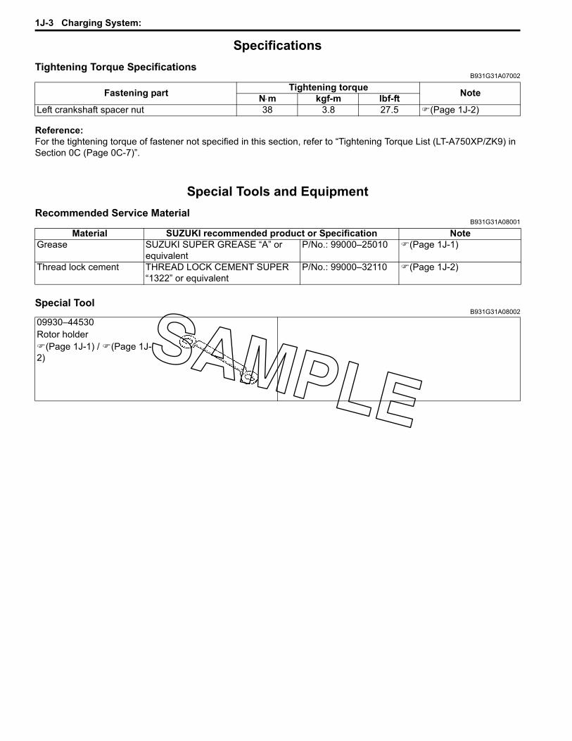
SpecificationsTightening Torque Specifications
B931G31A07002
Reference:For the tightening torque of fastener not specified in this section, refer to “Tightening Torque List (LT-A750XP/ZK9) in Section 0C (Page 0C-7)”.
Special Tools and EquipmentRecommended Service Material
B931G31A08001
Special ToolB931G31A08002
Fastening part Tightening torque NoteN⋅m kgf-m lbf-ftLeft crankshaft spacer nut 38 3.8 27.5 (Page 1J-2)
Material SUZUKI recommended product or Specification NoteGrease SUZUKI SUPER GREASE “A” or
equivalentP/No.: 99000–25010 (Page 1J-1)
Thread lock cement THREAD LOCK CEMENT SUPER “1322” or equivalent
P/No.: 99000–32110 (Page 1J-2)
09930–44530Rotor holder
(Page 1J-1) / (Page 1J-2)

Table of Contents 3- i
3
Section 3
CONTENTS
Driveline / Axle
NOTEFor the items with asterisk (*) in the “CONTENTS” below, refer to the same section of the service manual mentioned in the “FOREWORD” of this manual.
Precautions ................................................. 3-*Precautions..............................................................3-*
Precautions for Driveline / Axle ..............................3-*
Drive Chain / Drive Train / Drive Shaft... 3A-1Diagnostic Information and Procedures............ 3A-*
Drive Shaft Symptom Diagnosis ..........................3A-*Repair Instructions ..............................................3A-1
Front Drive Shaft Components ............................3A-*Front Drive Shaft Assembly Removal and
Installation..........................................................3A-*Front Drive Shaft Disassembly and Assembly .....3A-*Front Drive Shaft Inspection ................................3A-*Rear Drive Shaft Components .............................3A-*Rear Drive Shaft Assembly Removal and
Installation..........................................................3A-*Rear Drive Shaft Disassembly and Assembly......3A-*Rear Drive Shaft Inspection .................................3A-*Front Drive Shaft Components (LT-A750XP/
ZK9) ..................................................................3A-1Front Drive Shaft Disassembly and Assembly
(LT-A750XP/ZK9) .............................................3A-2Front Drive Shaft Inspection (LT-A750XP/
ZK9) ..................................................................3A-4Rear Drive Shaft Components (LT-A750XP/
ZK9) ..................................................................3A-5Rear Drive Shaft Disassembly and Assembly
(LT-A750XP/ZK9) .............................................3A-5Rear Drive Shaft Inspection (LT-A750XP/
ZK9) ..................................................................3A-5Special Tools and Equipment .............................3A-6
Recommended Service Material .........................3A-6Special Tool ........................................................3A-6
Differential.................................................3B-*Diagnostic Information and Procedures............ 3B-*
Drive Train Symptom Diagnosis...........................3B-*DTC “C20” (P1752) Diff-lock Relay Circuit
Malfunction.........................................................3B-*Repair Instructions .............................................. 3B-*
Front Drive (Differential) Components .................3B-*Front Drive (Differential) Construction..................3B-*Front Drive (Differential) Gear Oil Level
Inspection...........................................................3B-*
Front Drive (Differential) Gear Oil Replacement ..................................................... 3B-*
Front Drive (Differential) Assembly Removal and Installation .................................................. 3B-*
Front Drive (Differential) Assembly Disassembly and Assembly .............................. 3B-*
Front Drive (Differential) Related Parts Inspection.......................................................... 3B-*
Breather Rubber Case Inspection....................... 3B-*Front Drive (Differential) Gear Shim
Inspection and Selection ................................... 3B-*2WD/4WD/Diff-lock System Inspection............... 3B-*Rear Drive Breather Hose Routing Diagram....... 3B-*Final Gear Components ...................................... 3B-*Final Gear Construction ...................................... 3B-*Final Gear Oil Level Inspection ........................... 3B-*Final Gear Oil Replacement................................ 3B-*Final Gear Assembly Removal and
Installation ......................................................... 3B-*Final Gear Assembly Disassembly and
Assembly........................................................... 3B-*Final Gear Related Parts Inspection ................... 3B-*Final Gear Shim Inspection and Selection .......... 3B-*
Specifications....................................................... 3B-*Service Data........................................................ 3B-*Tightening Torque Specifications........................ 3B-*
Special Tools and Equipment ............................. 3B-*Recommended Service Material ......................... 3B-*Special Tool ........................................................ 3B-*
Transfer .....................................................3C-*Diagnostic Information and Procedures............ 3C-*
Transfer Symptom Diagnosis.............................. 3C-*Repair Instructions .............................................. 3C-*
Transfer Components ......................................... 3C-*Transfer Removal and Installation ...................... 3C-*Transfer Construction.......................................... 3C-*Counter Shaft / Reverse Idle Gear
Disassembly and Assembly .............................. 3C-*Gearshift Cam Components................................ 3C-*Gearshift System Construction ........................... 3C-*Gearshift Cam Disassembly and Assembly ........ 3C-*Transfer Gear Bearing Removal and
Installation ......................................................... 3C-*Transfer Gear Bearing Inspection ....................... 3C-*

3-ii Table of Contents
Transfer Related Parts Inspection....................... 3C-*Transfer Related Bearing Inspection................... 3C-*Gear Position (GP) Switch Inspection................. 3C-*Gear Position (GP) Switch Removal and
Installation......................................................... 3C-*Gearshift Shaft No. 2 / Gearshift Cam Plate
Removal and Installation................................... 3C-*Gearshift Linkage Inspection............................... 3C-*Gearshift Shaft Oil Seal Removal and
Installation......................................................... 3C-*Specifications....................................................... 3C-*
Service Data........................................................ 3C-*Special Tools and Equipment ............................. 3C-*
Recommended Service Material ......................... 3C-*Special Tool ........................................................ 3C-*
Propeller Shafts........................................3D-*Repair Instructions .............................................. 3D-*
Front Output Shaft Components ......................... 3D-*Front Output Shaft Removal and Installation ...... 3D-*Front Output Shaft Disassembly and
Assembly .......................................................... 3D-*
Front Output Shaft Related Parts Inspection ...... 3D-*Rear Output Shaft Components.......................... 3D-*Rear Output Shaft Removal and Installation....... 3D-*Rear Output Shaft Disassembly and
Assembly........................................................... 3D-*Rear Output Shaft Related Parts Inspection ....... 3D-*Rear Output Shaft Drive Bevel Gear Shim
Inspection and Adjustment................................ 3D-*Front Propeller Shaft Components...................... 3D-*Front Propeller Shaft Removal and
Installation ......................................................... 3D-*Front Propeller Shaft Related Parts
Inspection.......................................................... 3D-*Rear Propeller Shaft Components ...................... 3D-*Rear Propeller Shaft Removal and Installation .... 3D-*Rear Propeller Shaft Related Parts Inspection .... 3D-*
Specifications....................................................... 3D-*Service Data........................................................ 3D-*Tightening Torque Specifications........................ 3D-*
Special Tools and Equipment ............................. 3D-*Recommended Service Material ......................... 3D-*Special Tool ........................................................ 3D-*

Drive Chain / Drive Train / Drive Shaft: 3A-1
Driveline / AxleDrive Chain / Drive Train / Drive ShaftRepair Instructions
Front Drive Shaft Components (LT-A750XP/ZK9)B931G33106009
FWDFWD
1
2
3
7
6
5
4
8
9
10I931H1310012-03
1. Circlip 6. Inner boot band (Small) : Apply grease.2. Snap ring 7. Drive shaft : Apply water resistance grease.3. Stopper ring 8. Outer boot band (Small) : Do not reuse.4. Inner boot band (Large) 9. Outer boot5. Inner boot 10. Outer boot band (Large)

3A-2 Drive Chain / Drive Train / Drive Shaft:
Front Drive Shaft Disassembly and Assembly (LT-A750XP/ZK9)
B931G33106011Refer to “Front Drive Shaft Assembly Removal and Installation in related manual”.
Disassembly
CAUTION!
Do not disassemble the wheel side joint. If any damages are found, replace it with a new one.
1) Remove the boot band of the differential side joint.
2) Slide the boot toward the center of the front drive shaft and remove the stopper ring from the outer race.
3) Remove the outer race from the front drive shaft.
4) Wipe off any grease and remove the snap ring.
Special tool(A): 09900–06107 (Snap ring remover (Open
type))
5) Remove the cage from the front drive shaft.
6) Remove the boot band of the small diameter side.
I931H1310003-03
I831G1310006-01
I831G1310007-01
(A)
I831G1310022-01
I831G1310009-01
I931H1310004-02

Drive Chain / Drive Train / Drive Shaft: 3A-3
Assembly
CAUTION!
• Wash all parts before installation, clean the inside and outside of the boots with a cloth.
• Do not wash the boots in any commercially available degreaser, such as gasoline or kerosene. Washing in a degreaser causes deterioration of the boots.
1) Fit a boot on the drive shaft end, fitting the small diameter side of the boot to the shaft groove, fix its end with a new boot band.
CAUTION!
Replace the boot band with a new one.
2) Install the cage (1) on the shaft.
CAUTION!
Install the cage with the large diameter side “A” facing the shaft end.
3) Install the new snap ring to the cage.
CAUTION!
Replace the snap ring with a new one.
Special tool(A): 09900–06107 (Snap ring remover (Open
type))
4) Apply grease to the entire surface of the cage and the inside of the outer race.
NOTEThe tube of joint grease is included in the wheel side boot set or wheel side joint assembly of spare parts.
“A”: Large diameter “B”: Small diameter
I931H1310005-02
1
“A” “B”
I831G1310012-02
PositionWheel side Differential side
Grease: Quantity 60 g (2.1 oz) 60 g (2.1 oz)
(A)
I831G1310023-01
I831G1310013-01
I831G1310014-01

3A-4 Drive Chain / Drive Train / Drive Shaft:
5) Insert the cage into the outer race and install the new stopper ring to the groove of the outer race.
CAUTION!
• Replace the stopper ring with a new one.• Position the opening of stopper ring “C”
so that it will not be lined up with a ball.
6) After installing the boot on the outer race, insert a screw driver into the boot on the outer race side and allow air to enter the boot so that the air pressure in the boot becomes the same as the atmospheric pressure at the positions indicated in the figure.
7) Fix the boot on the outer race with a new boot band, taking care not to distort the boot.
8) Install the circlip (2) into the groove of front drive shaft spline.
CAUTION!
The removed circlip must be replaced with a new one.
9) Inspect the axle play by using a push-and-pull motion given to the axle shaft and wheel spindle.
Front Drive Shaft Inspection (LT-A750XP/ZK9)B931G33106012
Inspect the front drive shaft in the following procedures:1) Remove the front drive shaft assembly. Refer to
“Front Drive Shaft Assembly Removal and Installation in related manual”.
2) Check the drive shaft boots for twist and grease leak.If any defects are found, replace the defective parts with new ones.
3) Inspect the boots, circlip and boot bands for wear or damage. If any damages are found, replace them with new ones.
4) Install the front drive shaft assembly. Refer to “Front Drive Shaft Assembly Removal and Installation in related manual”.
“D”: Right side “F”: Rotation direction“E”: Left side “a”: 182.1 mm (7.2 in)
“C”
I831G1310015-01
A
VIEW A
“F”
“D” “E”
“F”
“a”
I931H1310006-03
2
I931H1310007-01
I931H1310008-01
I931H1310009-01
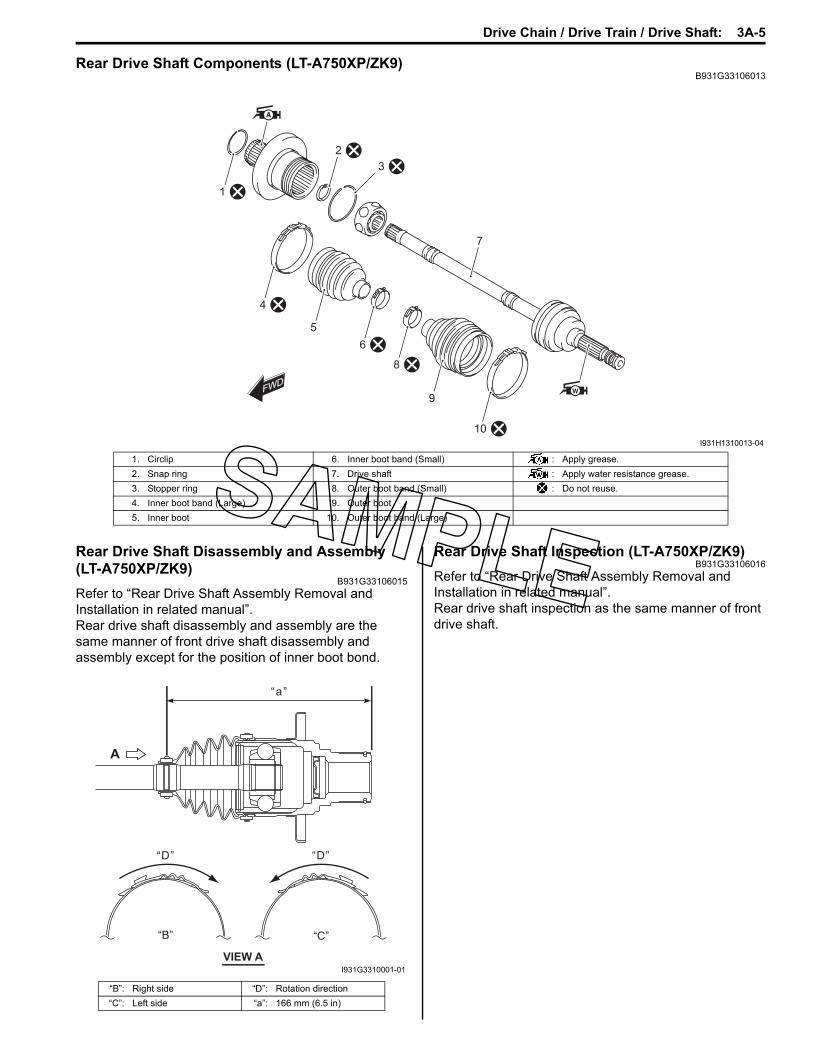
Drive Chain / Drive Train / Drive Shaft: 3A-5
Rear Drive Shaft Components (LT-A750XP/ZK9)B931G33106013
Rear Drive Shaft Disassembly and Assembly (LT-A750XP/ZK9)
B931G33106015Refer to “Rear Drive Shaft Assembly Removal and Installation in related manual”.Rear drive shaft disassembly and assembly are the same manner of front drive shaft disassembly and assembly except for the position of inner boot bond.
Rear Drive Shaft Inspection (LT-A750XP/ZK9)B931G33106016
Refer to “Rear Drive Shaft Assembly Removal and Installation in related manual”.Rear drive shaft inspection as the same manner of front drive shaft.
FWDFWD
1
4
5
6
8
9
2
7
3
10I931H1310013-04
1. Circlip 6. Inner boot band (Small) : Apply grease.2. Snap ring 7. Drive shaft : Apply water resistance grease.3. Stopper ring 8. Outer boot band (Small) : Do not reuse.4. Inner boot band (Large) 9. Outer boot5. Inner boot 10. Outer boot band (Large)
“B”: Right side “D”: Rotation direction“C”: Left side “a”: 166 mm (6.5 in)
A
VIEW A
“D”
“B” “C”
“D”
“a”
I931G3310001-01

3A-6 Drive Chain / Drive Train / Drive Shaft:
Special Tools and EquipmentRecommended Service Material
B931G33108001NOTERequired service material is also described in the following.“Front Drive Shaft Components (LT-A750XP/ZK9) (Page 3A-1)”“Rear Drive Shaft Components (LT-A750XP/ZK9) (Page 3A-5)”
Special ToolB931G33108002
09900–06107Snap ring remover (Open type)
(Page 3A-2) / (Page 3A-3)

Table of Contents 4- i
4
Section 4
CONTENTS
Brake
NOTEFor the items with asterisk (*) in the “CONTENTS” below, refer to the same section of the service manual mentioned in the “FOREWORD” of this manual.
Precautions ................................................. 4-*Precautions..............................................................4-*
Precautions for Brake System ...............................4-*Brake Fluid Information..........................................4-*
Brake Control System and Diagnosis ... 4A-1Schematic and Routing Diagram........................4A-1
Front Brake Hose Routing Diagram.....................4A-*Rear Blake Cable Routing Diagram.....................4A-*Front Brake Hose Routing Diagram (LT-
A750XP/ZK9) ....................................................4A-1Diagnostic Information and Procedures............ 4A-*
Brake Symptom Diagnosis...................................4A-*Repair Instructions ..............................................4A-2
Brake Pedal Height Inspection and Adjustment .........................................................4A-*
Front Brake Light Switch Inspection ....................4A-*Rear Brake Light Switch Inspection .....................4A-*Rear Brake Switch Inspection and Adjustment .....4A-*Parking / Rear Brake Light Switch Inspection......4A-*Parking Brake Lever Switch Inspection................4A-*Brake Fluid Level Check ......................................4A-*Front Brake Hose Inspection ...............................4A-*Air Bleeding from Front Brake Fluid Circuit..........4A-*Brake Fluid Replacement.....................................4A-*Front Brake Hose Removal and Installation.........4A-*Rear Brake Cable Removal and Installation ........4A-*Front Brake Master Cylinder Components...........4A-*Front Brake Master Cylinder Assembly
Removal and Installation....................................4A-*Front Brake Master Cylinder / Brake Lever
Disassembly and Assembly ...............................4A-*Front Brake Master Cylinder Parts Inspection .....4A-*Rear Brake Pedal Construction ...........................4A-*Rear Brake Pedal Removal and Installation ........4A-*Front Brake Hose Removal and Installation
(LT-A750XP/ZK9) .............................................4A-2Rear Brake Pedal Construction (LT-A750XP/
ZK9) ..................................................................4A-3Rear Brake Pedal Removal and Installation
(LT-A750XP/ZK9) .............................................4A-3Specifications.......................................................4A-5
Service Data ........................................................4A-*Tightening Torque Specifications........................4A-5
Special Tools and Equipment .............................4A-5Special Tool ........................................................ 4A-*Recommended Service Material .........................4A-5
Front Brakes .............................................4B-*Precautions........................................................... 4B-*
Precautions for Front Brakes .............................. 4B-*Repair Instructions .............................................. 4B-*
Front Brake Components .................................... 4B-*Front Brake Pad Inspection................................. 4B-*Front Brake Pad Replacement............................ 4B-*Front Brake Caliper Removal and Installation..... 4B-*Front Brake Caliper Disassembly and
Assembly........................................................... 4B-*Front Brake Caliper Parts Inspection .................. 4B-*Front Brake Disc Removal and Installation ......... 4B-*Front Brake Disc Inspection ................................ 4B-*
Specifications....................................................... 4B-*Service Data........................................................ 4B-*Tightening Torque Specifications........................ 4B-*
Special Tools and Equipment ............................. 4B-*Recommended Service Material ......................... 4B-*Special Tool ........................................................ 4B-*
Rear Brakes...............................................4C-*Precautions........................................................... 4C-*
Precautions for Rear Brake................................. 4C-*Repair Instructions .............................................. 4C-*
Rear Brake Components..................................... 4C-*Rear Brake Friction Plate Inspection................... 4C-*Rear Brake Friction Plate Replacement.............. 4C-*Rear Brake Assembly Removal and
Installation ......................................................... 4C-*Rear Brake Disassembly and Assembly ............. 4C-*Rear Brake Parts Inspection ............................... 4C-*
Specifications....................................................... 4C-*Service Data........................................................ 4C-*Tightening Torque Specifications........................ 4C-*
Special Tools and Equipment ............................. 4C-*Recommended Service Material ......................... 4C-*Special Tool ........................................................ 4C-*
Parking Brake ...........................................4D-*Schematic and Routing Diagram........................ 4D-*

4-ii Table of Contents
Parking / Rear Brake Cable Routing Diagram .... 4D-*Repair Instructions .............................................. 4D-*
Parking / Rear Brake Inspection and Adjustment ........................................................ 4D-*
Parking / Rear Brake Cable Removal and Installation......................................................... 4D-*
Parking / Rear Brake Lever Components ........... 4D-*
Parking / Rear Brake Lever Removal and Installation ......................................................... 4D-*
Parking / Rear Brake Light Switch Inspection ..... 4D-*Parking / Rear Brake Relay Inspection ............... 4D-*
Specifications....................................................... 4D-*Tightening Torque Specifications........................ 4D-*
Special Tools and Equipment ............................. 4D-*Recommended Service Material ......................... 4D-*

Brake Control System and Diagnosis: 4A-1
BrakeBrake Control System and DiagnosisSchematic and Routing Diagram
Front Brake Hose Routing Diagram (LT-A750XP/ZK9)B931G34102003
1
“B”
2
“C”
3
4
5 5
7
4
(a)8 9
4
(a)89
10
11
11
12
(a)8
11
“E” 6
“F”
(b)
“D”
(b)
“A”
“D”
“D”
I931H1410043-05
1. Master cylinder 11. Suspension upper arm2. Front brake hose No. 1 12. Radiator hose3. Front brake pipe “A”: UP mark4. Front brake hose No. 2 “B”: After the brake hose union has contacted the reservoir bottom.5. Front brake caliper “C”: Pass the brake hose behind the throttle cable.6. Frame “D”: Fix the brake hose to the it guide firmly.7. Steering shaft “E”: Pass the brake hose No. 2 between the radiator lower hose and frame.8. Union bolt “F”: Pass the brake hose inside of the suspension arm.9. Stopper
: After the brake hose union has contacted the stopper, tighten the union bolt.
: 23 N⋅m (2.3 kgf-m, 16.5 lbf-ft)
10. Stopper: After the brake hose clamp has contacted the suspension upper arm, tighten the stopper bolt.
: 16 N⋅m (1.6 kgf-m, 11.5 lbf-ft)

4A-2 Brake Control System and Diagnosis:
Repair InstructionsFront Brake Hose Removal and Installation (LT-A750XP/ZK9)
B931G34106019Removal
CAUTION!
Make sure that the vehicle is supported securely.
1) Remove the front fender. Refer to “Front Side Exterior Parts Removal and Installation in Section 9D in related manual”.
2) Drain brake fluid. Refer to “Brake Fluid Replacement in related manual”.
3) Loosen the flare nuts (1) and disconnect the brake pipe.
4) Remove the front brake hoses as shown in the front brake hose routing diagram. Refer to “Front Brake Hose Routing Diagram (LT-A750XP/ZK9) (Page 4A-1)”.
Installation
CAUTION!
The seal washers should be replaced with the new ones to prevent fluid leakage.
1) Install the front brake hose as shown in the front brake hose routing diagram. Refer to “Front Brake Hose Routing Diagram in related manual”.
2) Tighten the brake flare nut (1) to the specified torque.
Tightening torqueBrake pipe flare nut (a): 16 N·m (1.6 kgf-m, 11.5 lbf-ft)
3) Bleed air from the front brake system. Refer to “Air Bleeding from Front Brake Fluid Circuit in related manual”.
4) Install the front fender. Refer to “Front Side Exterior Parts Removal and Installation in Section 9D in related manual”.
1 1
I931G3410001-02
(a)1 (a)1
I931G3410009-01

Brake Control System and Diagnosis: 4A-3
Rear Brake Pedal Construction (LT-A750XP/ZK9)B931G34106020
Rear Brake Pedal Removal and Installation (LT-A750XP/ZK9)
B931G34106021Removal1) Remove the right inner fender. Refer to “Front Side
Exterior Parts Removal and Installation in Section 9D in related manual”.
2) Remove the right mud guard. Refer to “Rear Side Exterior Parts Removal and Installation in Section 9D in related manual”.
3) Remove the rear brake light switch spring (1).4) Disconnect the rear brake cable (2). Refer to “Rear
Brake Cable Removal and Installation in related manual”.
“a”
“A”
“b”
“c”
“B”
3
(a)5
4
241
“B”“A”
(b)6
I931G3410002-01
1. Rear brake pedal 6. Rear brake pedal screw “B”: Anchoring point (Pedal side)2. Rear brake light switch “a”: 12.5 – 22.5 mm (0.49 – 0.89 in) : 60 N⋅m (6.0 kgf-m, 43.5 lbf-ft)3. Washer “b”: 83.2 mm (3.28 in) : 4.5 N⋅m (0.45 kgf-m, 3.0 lbf-ft)4. Rear brake pedal shaft “c”: 17.5 mm (0.69 in) : Apply water resistance grease.5. Rear brake pedal shaft nut “A”: Anchoring point (Footrest side)
2
1
I931G3410003-02

4A-4 Brake Control System and Diagnosis:
5) Remove the rear brake pedal shaft (3).6) Remove the rear brake pedal (4) and rear brake
pedal spring (5).
7) Remove the dust seals (6) if necessary.
CAUTION!
If there are wear or damage, replace the dust seals (6) with new ones.
8) Remove the washers (7).
InstallationInstall the rear brake pedal in the reverse order of removal. Pay attention to the following points:• Apply grease to the lip of dust seals and washers.
CAUTION!
Never reuse the removed dust seals with new ones.
: Grease 99000–25160 (Water resistance grease or equivalent)
• Apply grease to the rear brake pedal shaft (1).
: Grease 99000–25160 (Water resistance grease or equivalent)
4
3
5
I931G3410010-01
6
6
I931G3410004-01
7
I931G3410005-01
I931G3410006-02
1
I931H1410035-01

Brake Control System and Diagnosis: 4A-5
• Install the rear brake pedal shaft (1) and tighten the brake pedal shaft nut (2) to the specified torque.
Tightening torqueRear brake pedal shaft nut (a): 60 N·m (6.0 kgf-m, 43.5 lbf-ft)
• After installed rear brake cable, adjust the adjuster nut. Refer to “Rear Brake Pedal / Rear Brake (Parking Brake) Lever Inspection and Adjustment in Section 0B in related manual”.
• Install the removed parts.
SpecificationsTightening Torque Specifications
B931G34107002
NOTEThe specified tightening torque is described in the following.“Front Brake Hose Routing Diagram (LT-A750XP/ZK9) (Page 4A-1)”“Rear Brake Pedal Construction (LT-A750XP/ZK9) (Page 4A-3)”
Reference:For the tightening torque of fastener not specified in this section, refer to “Tightening Torque List (LT-A750XP/ZK9) in Section 0C (Page 0C-7)”.
Special Tools and EquipmentRecommended Service Material
B931G34108003
NOTERequired service material is also described in the following.“Rear Brake Pedal Construction (LT-A750XP/ZK9) (Page 4A-3)”
1
(a)2
I931G3410007-01
Fastening part Tightening torque NoteN⋅m kgf-m lbf-ftBrake pipe flare nut 16 1.6 11.5 (Page 4A-2)Rear brake pedal shaft nut 60 6.0 43.5 (Page 4A-5)
Material SUZUKI recommended product or Specification NoteGrease Water resistance grease or
equivalentP/No.: 99000–25160 (Page 4A-4) / (Page 4A-
4)

4A-6 Brake Control System and Diagnosis:

Table of Contents 6- i
6
Section 6
CONTENTS
Steering
NOTEFor the items with asterisk (*) in the “CONTENTS” below, refer to the same section of the service manual mentioned in the “FOREWORD” of this manual.
Precautions .................................................6-1Precautions............................................................. 6-1
Precautions for Steering ........................................6-*Precautions for Steering (LT-A750XP/ZK9) .......... 6-1
Steering General Diagnosis.................... 6A-1Diagnostic Information and Procedures............6A-1
Steering Symptom Diagnosis...............................6A-*Steering Symptom Diagnosis (LT-A750XP/
ZK9) ..................................................................6A-1
Steering / Handlebar................................ 6B-1Repair Instructions ..............................................6B-1
Steering / Handlebars Components.....................6B-*Steering / Handlebars Assembly Construction .....6B-*Handlebars Removal and Installation ..................6B-*Handlebars Inspection .........................................6B-*Steering Shaft Removal and Installation..............6B-*Tie-rod / Tie-rod End Removal and
Installation..........................................................6B-*Steering Parts Inspection.....................................6B-*Steering / Handlebars Components (LT-
A750XP/ZK9) ....................................................6B-1Steering / Handlebars Assembly Construction
(LT-A750XP/ZK9) .............................................6B-2Handlebars Removal and Installation (LT-
A750XP/ZK9) ....................................................6B-3Handlebars Inspection (LT-A750XP/ZK9)...........6B-5Steering Shaft Removal and Installation (LT-
A750XP/ZK9) ....................................................6B-6Tie-rod / Tie-rod End Removal and
Installation (LT-A750XP/ZK9) ...........................6B-8Steering Related Parts Inspection (LT-
A750XP/ZK9) ....................................................6B-9Specifications.....................................................6B-10
Service Data ........................................................6B-*Service Data (LT-A750XP/ZK9)........................6B-10Tightening Torque Specifications......................6B-11
Special Tools and Equipment ...........................6B-11Recommended Service Material .......................6B-11Special Tool ......................................................6B-11
Power Assisted Steering System........... 6C-1Precautions...........................................................6C-1
Precautions for EPS (LT-A750XP/ZK9) ..............6C-1
P/S System Note (LT-A750XP/ZK9) ...................6C-1Precautions in Diagnosing Troubles (LT-
A750XP/ZK9) ....................................................6C-1General Description .............................................6C-2
P/S System Description (LT-A750XP/ZK9).........6C-2EPS Diagnosis General Description (LT-
A750XP/ZK9) ....................................................6C-5Self Diagnostic System Description (LT-
A750XP/ZK9) ....................................................6C-5Fail-safe Function Description (LT-A750XP/
ZK9) ..................................................................6C-5Schematic and Routing Diagram........................6C-6
EPS Wiring Diagram (LT-A750XP/ZK9)..............6C-6EPS Control Unit Diagram (LT-A750XP/ZK9).....6C-7EPS System Wiring Harness Routing
Diagram (LT-A750XP/ZK9) ...............................6C-8Component Location ...........................................6C-8
EPS Components Location (LT-A750XP/ZK9) ..................................................................6C-8
Diagnostic Information and Procedures............6C-9EPS Troubleshooting (LT-A750XP/ZK9).............6C-9Pre-diagnosis Inspection (LT-A750XP/ZK9) .....6C-10EPS System Check (LT-A750XP/ZK9) .............6C-12DTC (Diagnostic Trouble Code) Output (LT-
A750XP/ZK9) ..................................................6C-19DTC (Diagnostic Trouble Code) Deleting (LT-
A750XP/ZK9) ..................................................6C-21SDS Check (LT-A750XP/ZK9) ..........................6C-24DTC Table (LT-A750XP/ZK9) ...........................6C-25DTC “C1111”: Torque Sensor (Main) Circuit
Malfunction (LT-A750XP/ZK9) ........................6C-26DTC “C1113”: Torque Sensor (Main / Sub)
Circuit Correlation Malfunction (LT-A750XP/ZK9) ................................................................6C-29
DTC “C1114”: Torque Sensor Power Supply Circuit Malfunction (LT-A750XP/ZK9) .............6C-33
DTC “C1115”: Torque Sensor (Sub) Circuit Malfunction (LT-A750XP/ZK9) ........................6C-35
DTC “C1121”: Vehicle Speed Signal Circuit Malfunction (LT-A750XP/ZK9) ........................6C-38
DTC “C1122”: Engine Speed Signal Circuit Malfunction (LT-A750XP/ZK9) ........................6C-41
DTC “C1141”, “C1142”, “C1143”, “C1145” EPS Motor Circuit Malfunction (LT-A750XP/ZK9) ................................................................6C-44

6-ii Table of Contents
DTC “C1153” EPS Control Unit Supply Voltage Circuit Malfunction (LT-A750XP/ZK9) ................................................................6C-46
DTC “C1152”, “C1154”, “C1155” EPS Control Unit Malfunction (LT-A750XP/ZK9).................6C-47
Repair Instructions ............................................6C-48EPS Control Unit Construction (LT-A750XP/
ZK9) ................................................................6C-48EPS Control Unit Removal and Installation
(LT-A750XP/ZK9) ...........................................6C-48
EPS Body Assembly Components (LT-A750XP/ZK9) ..................................................6C-50
EPS Body Assembly Removal and Installation (LT-A750XP/ZK9) .........................6C-50
EPS Motor Inspection (LT-A750XP/ZK9)..........6C-53Specifications.....................................................6C-54
Tightening Torque Specifications......................6C-54Special Tools and Equipment ...........................6C-54
Recommended Service Material .......................6C-54Special Tool ......................................................6C-55

Precautions: 6-1
SteeringPrecautionsPrecautions
Precautions for Steering (LT-A750XP/ZK9)B931G36000002
Refer to “General Precautions in Section 00 in related manual” and “Precautions for EPS (LT-A750XP/ZK9) in Section 00 (Page 00-1)”.
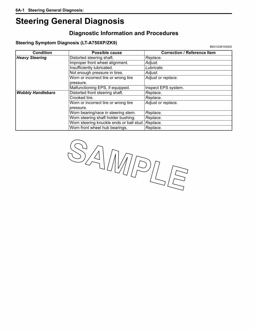
6A-1 Steering General Diagnosis:
SteeringSteering General DiagnosisDiagnostic Information and Procedures
Steering Symptom Diagnosis (LT-A750XP/ZK9)B931G36104002
Condition Possible cause Correction / Reference ItemHeavy Steering Distorted steering shaft. Replace.
Improper front wheel alignment. Adjust.Insufficiently lubricated. Lubricate.Not enough pressure in tires. Adjust.Worn or incorrect tire or wrong tire pressure.
Adjust or replace.
Malfunctioning EPS, if equipped. Inspect EPS system.Wobbly Handlebars Distorted front steering shaft. Replace.
Crooked tire. Replace.Worn or incorrect tire or wrong tire pressure.
Adjust or replace.
Worn bearing/race in steering stem. Replace.Worn steering shaft holder bushing. Replace.Worn steering knuckle ends or ball stud. Replace.Worn front wheel hub bearings. Replace.

Steering / Handlebar: 6B-1
SteeringSteering / HandlebarRepair Instructions
Steering / Handlebars Components (LT-A750XP/ZK9)B931G36206008
1
2
3
4
5
7
12
13
14
15
16
17
18
12
“A”
“A”
“A”
12
20
20
19
“A”
(a)
10
11
9
FWDFWD
8
6
I931G3620028-02
1. Handlebars 10. Lower dust seal 19. Handlebar left switch assembly2. Handlebar upper clamp 11. Steering arm plate 20. Handle grip3. Handlebar holder 12. Cotter pin “A”: Apply grip bond.4. Steering shaft plate 13. Tie-rod : 4 N⋅m (0.4 kgf-m, 3.0 lbf-ft)5. EPS body assembly 14. Tie-rod end : Apply thread lock to the thread part.6. Steering shaft 15. Cable guide : Apply water resistance grease.7. Steering shaft bushing 16. Throttle cable : Do not reuse.8. Dust seal 17. Parking brake cable9. O-ring 18. Throttle case assembly
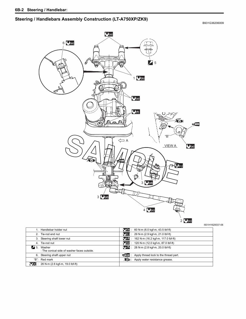
6B-2 Steering / Handlebar:
Steering / Handlebars Assembly Construction (LT-A750XP/ZK9)B931G36206009
(a)
(a)
(f)
(e)6
(d)3
(c)4
(c)2
(d)3
(c)2
(a)
“B”
VIEW A
A
5
(a)
(b)1
I931H1620037-06
1. Handlebar holder nut : 60 N⋅m (6.0 kgf-m, 43.5 lbf-ft)2. Tie-rod end nut : 29 N⋅m (2.9 kgf-m, 21.0 lbf-ft)3. Steering shaft lower nut : 162 N⋅m (16.2 kgf-m, 117.0 lbf-ft)4. Tie-rod nut : 120 N⋅m (12.0 kgf-m, 87.0 lbf-ft)5. Washer
: The conical side of washer faces outside.: 28 N⋅m (2.8 kgf-m, 20.0 lbf-ft)
6. Steering shaft upper nut : Apply thread lock to the thread part.“B”: Red mark : Apply water resistance grease.
: 26 N⋅m (2.6 kgf-m, 19.0 lbf-ft)

Steering / Handlebar: 6B-3
Handlebars Removal and Installation (LT-A750XP/ZK9)
B931G36206010
Removal1) Remove the auxiliary headlight cover. Refer to
“Auxiliary Headlight Removal and Installation in Section 9B in related manual”
2) Remove the combination meter. Refer to “Combination Meter Removal and Installation in Section 9C in related manual”.
3) Remove the clamps.4) Disconnect the brake hose from the hose guide.
5) Remove the following parts from the handlebars (right side).a) Right grip (1)b) Front brake master cylinder/Front brake lever (2)
CAUTION!
Do not turn the front brake master cylinder upside down.
c) Throttle lever case (3)
6) Remove the following parts from left handlebars (left side).a) Left grip (4)b) Left switch box (5)c) Horn button (For P-17, 24)d) Emergency switch (For P-17)
7) Disconnect the parking brake cable (6) from left brake lever.
8) Remove the clamp.
I931G3620001-01
1
2
3
I931G3620002-01
4 5
I931G3620003-01
6
I931H1620004-01
I931G3620004-01

6B-4 Steering / Handlebar:
9) Remove the handlebar upper clamps (7) and handlebars (8).
10) Remove the left brake lever from the handlebars (left side).
InstallationInstall the handlebars in the reverse order of removal. Pay attention to the following points:• Install the left brake lever (1) to the handlebars.• Align the punch mark “A” on the handlebars with the
mating surface “B” of rear brake lever (1).• Tighten the rear brake lever holder clamp bolt (2) to
the specified torque.
Tightening torqueRear brake lever holder clamp bolt (a): 11 N·m (1.1 kgf-m, 8.0 lbf-ft)
• Install the washers (3) and bolts (4) as shown in the steering/handlebars construction. Refer to “Steering / Handlebars Assembly Construction (LT-A750XP/ZK9) (Page 6B-2)”.
• Set the handlebars so that its punch mark “B” aligns with the mating surface of the left handlebar holder.
• Tighten the handlebar clamp bolts (4) to the specified torque.
NOTEFirst tighten the handlebar clamp bolts (4) (front ones) to the specified torque.
Tightening torqueHandlebar clamp bolt (b): 26 N·m (2.6 kgf-m, 19.0 lbf-ft)
8
7
I931G3620027-01
I831G1620006-05
(a)2
1
“A”
“B”
I931H1620008-01
“a”: Clearance
4
4
3
3
“B”
I931H1620009-02
“a”
(b)4 (b)
FWD
I931H1620010-01

Steering / Handlebar: 6B-5
• Apply adhesive agent to the handlebar right and left end and right and left grip inner wall.
: Handle grip bond (Handle Grip Bond (commercially available))
• Insert the projection “D” of the left handlebar switch assembly into the hole of the handlebars.
• Tighten the left handlebar switch screws (6).
• Install the master cylinder. Refer to “Front Brake Master Cylinder Assembly Removal and Installation in Section 4A in related manual”.
• Align the punch mark “E” on the handlebars with the mating surface “F” of the throttle lever case.
• Tighten the throttle lever case bolts (7) to the specified torque.
Tightening torqueThrottle lever case bolt (c): 4 N·m (0.4 kgf-m, 3.0 lbf-ft)
Handlebars Inspection (LT-A750XP/ZK9)B931G36206011
Refer to “Handlebars Inspection in related manual”.
5. Handlebar“C”: Apply handle grip bond.
“C”
“C”
5
I831G1620014-02
“D”
I931G3620005-01
6
I931G3620006-01
“E”
“F”
I931G3620007-01
(c)7
I931G3620008-01

6B-6 Steering / Handlebar:
Steering Shaft Removal and Installation (LT-A750XP/ZK9)
B931G36206012Removal1) Remove the EPS control unit. Refer to “EPS Control
Unit Removal and Installation (LT-A750XP/ZK9) in Section 6C (Page 6C-48)”.
2) Remove the EPS body assembly. Refer to “EPS Body Assembly Removal and Installation (LT-A750XP/ZK9) in Section 6C (Page 6C-50)”.
3) Disconnect the tie-rod ends with the special tool. Refer to “Front Wheel Hub / Steering Knuckle Removal and Installation in Section 2B in related manual”.
WARNING!
When using the tie-rod end remover, keep clear of the tie-rod end because it may come loose with some force and could strike you.
CAUTION!
Make sure that the vehicle is supported securely.
Special tool(A): 09942–72410 (Tie-rod end remover)
4) Remove the cotter pin (1), nut (2) and washer (3).
5) Remove the steering arm plate (4) and steering shaft (5).
6) Remove the lower dust seal (6) and O-ring (7).
7) Remove the steering shaft bushing (8) and dust seal (9) with the special tools and suitable socket wrench.
Special tool(A): 09924–84521 (Bearing installer set)(B): 09930–30721 (Rotor remover)
(A)
I931G3620009-01
1
2
3
I931G3620010-01
4
5
I931G3620011-01
6
7
I931G3620012-01
8
9
(A)
(B)
I931G3620013-01
(B)
(C)
8
9
(B)
I931H1620020-02

Steering / Handlebar: 6B-7
InstallationInstall the steering shaft in the reverse order of removal. Pay attention to the following points:• Install the steering shaft bushing (1) along with dust
seal (2) with the special tool.
Special tool(A): 09924–84521 (Bearing installer set)
• Apply grease to the steering shaft bushing (1) and dust seal (2) and install them.
: Grease 99000–25160 (Water resistance grease or equivalent)
• Apply grease to the lower dust seal (3) and O-ring (4).
CAUTION!
The removed O-ring must be replaced with a new one.
: Grease 99000–25160 (Water resistance grease or equivalent)
• Apply grease to the steering shaft.
: Grease 99000–25160 (Water resistance grease or equivalent)
• Install the steering shaft.• When installing the steering arm plate (5), align the
wide spline “A” of steering shaft (6) with the wide spline “B” of steering arm plate (5).
• Apply a small quality thread lock to the thread part of steering shaft.
: Thread lock cement 99000–32030 (THREAD LOCK CEMENT SUPER “1303” or equivalent)
• Tighten the steering shaft lower nut (7) to the specified torque.
Tightening torqueSteering shaft lower nut (a): 162 N·m (16.2 kgf-m, 117.0 lbf-ft)
(A)2
1
I931G3620014-01
2
1
I931G3620015-01
4
3
I931G3620016-01
I931G3620017-01
6
5
“A”
“B”6
I931G3620018-01
(a)7
I931G3620019-01

6B-8 Steering / Handlebar:
• Install the cotter pin (8).
CAUTION!
The removed cotter pin (8) must be replaced with a new one.
• Install EPS body assembly. Refer to “EPS Body Assembly Removal and Installation (LT-A750XP/ZK9) in Section 6C (Page 6C-50)”.
• Install the EPS control unit. Refer to “EPS Control Unit Removal and Installation (LT-A750XP/ZK9) in Section 6C (Page 6C-48)”.
• Install the handlebars. Refer to “Handlebars Removal and Installation in related manual”.
• Install the front fender. Refer to “Front Side Exterior Parts Removal and Installation in Section 9D in related manual”.
• Install the front wheels. Refer to “Front / Rear Wheel Removal and Installation in Section 2D in related manual”.
• After installing these parts, adjust the toe. Refer to “Toe Adjustment (LT-A750XP/ZK9) in Section 0B (Page 0B-2)”.
Tie-rod / Tie-rod End Removal and Installation (LT-A750XP/ZK9)
B931G36206013
WARNING!
When using the tie-rod end remover, keep clear of the tie-rod end because it may come loose with some force and could strike you.
Removal1) Remove the tie-rod end with the special tool. Refer
to “Front Wheel Hub / Steering Knuckle Removal and Installation in Section 2B in related manual”.
Special tool(A): 09942–72410 (Tie-rod end remover)
2) Remove the cotter pin, tie-rod end nut and washer.
3) Remove the steering arm plate (1) with a special tool.
Special tool(A): 09942–72410 (Tie rod end remover)
8
I931G3620020-01
(A)
I931G3620021-01
I931G3620022-01
1
(A)
I931H1620030-01
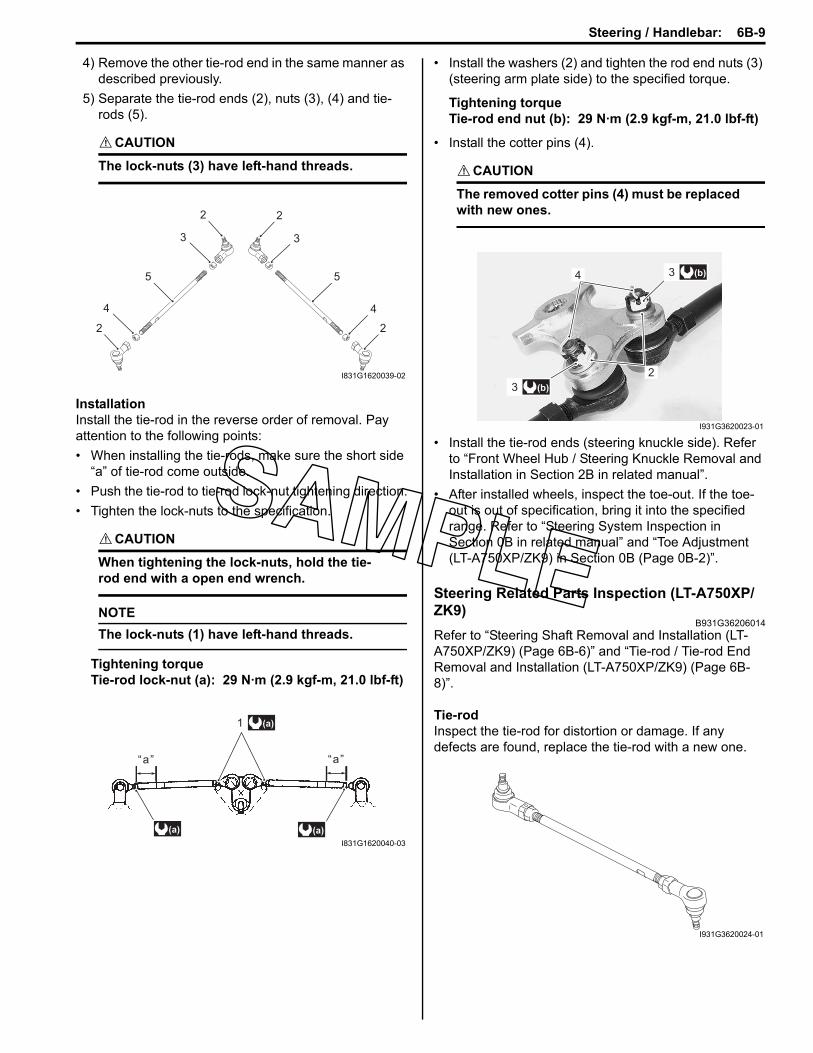
Steering / Handlebar: 6B-9
4) Remove the other tie-rod end in the same manner as described previously.
5) Separate the tie-rod ends (2), nuts (3), (4) and tie-rods (5).
CAUTION!
The lock-nuts (3) have left-hand threads.
InstallationInstall the tie-rod in the reverse order of removal. Pay attention to the following points:• When installing the tie-rods, make sure the short side
“a” of tie-rod come outside.• Push the tie-rod to tie-rod lock-nut tightening direction.• Tighten the lock-nuts to the specification.
CAUTION!
When tightening the lock-nuts, hold the tie-rod end with a open end wrench.
NOTEThe lock-nuts (1) have left-hand threads.
Tightening torqueTie-rod lock-nut (a): 29 N·m (2.9 kgf-m, 21.0 lbf-ft)
• Install the washers (2) and tighten the rod end nuts (3) (steering arm plate side) to the specified torque.
Tightening torqueTie-rod end nut (b): 29 N·m (2.9 kgf-m, 21.0 lbf-ft)
• Install the cotter pins (4).
CAUTION!
The removed cotter pins (4) must be replaced with new ones.
• Install the tie-rod ends (steering knuckle side). Refer to “Front Wheel Hub / Steering Knuckle Removal and Installation in Section 2B in related manual”.
• After installed wheels, inspect the toe-out. If the toe-out is out of specification, bring it into the specified range. Refer to “Steering System Inspection in Section 0B in related manual” and “Toe Adjustment (LT-A750XP/ZK9) in Section 0B (Page 0B-2)”.
Steering Related Parts Inspection (LT-A750XP/ZK9)
B931G36206014Refer to “Steering Shaft Removal and Installation (LT-A750XP/ZK9) (Page 6B-6)” and “Tie-rod / Tie-rod End Removal and Installation (LT-A750XP/ZK9) (Page 6B-8)”.
Tie-rodInspect the tie-rod for distortion or damage. If any defects are found, replace the tie-rod with a new one.
2
2 2
2
3
4 4
5 5
3
I831G1620039-02
“a”“a”
(a)1
(a) (a)
I831G1620040-03
4
2
(b)3
(b)3
I931G3620023-01
I931G3620024-01

6B-10 Steering / Handlebar:
Tie-rod EndInspect the tie-rod ends for smooth movement. If there are any abnormalities, replace the tie-rod ends with new ones. Inspect the tie-rod end boots for wear or damage. If any defects are found, replace the tie-rod ends with new ones.
Steering ShaftInspect the steering shaft for distortion or bend. If any defects are found, replace the steering shaft with a new one.
Steering Shaft Bushing and Dust SealInspect the steering shaft bushing (1), dust seal (2) and lower dust seal (3) for wear or damage. If any defects are found, replace them with new ones.
SpecificationsService Data (LT-A750XP/ZK9)
B931G36207003Wheel
I931G3620025-01
I931H1620034-01
3
2
1
I931H1620035-01
Item Standard LimitSteering angle 46° (right & left) —Turning radius 3.1 m (10.2 ft) —Toe-out (with 75 kg, 165 lbs) 5 ± 4 mm (0.20 ± 0.16 in) —Camber –1.3° —Caster 3.3° —

Steering / Handlebar: 6B-11
Tightening Torque SpecificationsB931G36207004
NOTEThe specified tightening torque is described in the following.“Steering / Handlebars Components (LT-A750XP/ZK9) (Page 6B-1)”“Steering / Handlebars Assembly Construction (LT-A750XP/ZK9) (Page 6B-2)”
Reference:For the tightening torque of fastener not specified in this section, refer to “Tightening Torque List (LT-A750XP/ZK9) in Section 0C (Page 0C-7)”.
Special Tools and EquipmentRecommended Service Material
B931G36208001
NOTERequired service material is also described in the following.“Steering / Handlebars Components (LT-A750XP/ZK9) (Page 6B-1)”“Steering / Handlebars Assembly Construction (LT-A750XP/ZK9) (Page 6B-2)”
Special ToolB931G36208002
Fastening part Tightening torque NoteN⋅m kgf-m lbf-ftRear brake lever holder clamp bolt 11 1.1 8.0 (Page 6B-4)Handlebar clamp bolt 26 2.6 19.0 (Page 6B-4)Throttle lever case bolt 4 0.4 3.0 (Page 6B-5)Steering shaft lower nut 162 16.2 117.0 (Page 6B-7)Tie-rod lock-nut 29 2.9 21.0 (Page 6B-9)Tie-rod end nut 29 2.9 21.0 (Page 6B-9)
Material SUZUKI recommended product or Specification NoteGrease Water resistance grease or
equivalentP/No.: 99000–25160 (Page 6B-7) / (Page 6B-
7) / (Page 6B-7)Handle grip bond Handle Grip Bond (commercially
available)— (Page 6B-5)
Thread lock cement THREAD LOCK CEMENT SUPER “1303” or equivalent
P/No.: 99000–32030 (Page 6B-7)
09924–84521 09930–30721Bearing installer set Rotor remover
(Page 6B-6) / (Page 6B-7)
(Page 6B-6)
09942–72410Tie-rod end remover
(Page 6B-6) / (Page 6B-8) / (Page 6B-8)

6C-1 Power Assisted Steering System:
SteeringPower Assisted Steering SystemPrecautions
Precautions for EPS (LT-A750XP/ZK9)B931G36300001
Refer to “General Precautions in Section 00 in related manual” and “Precautions for EPS (LT-A750XP/ZK9) in Section 00 (Page 00-1)”.
NOTEWhen repairing EPS system, remove the front fender. Refer to “Front Side Exterior Parts Removal and Installation in Section 9D in related manual”.
P/S System Note (LT-A750XP/ZK9)B931G36300002
CAUTION!
Never remove the torque sensor to prevent accident and damage.
NOTEEPS body assembly fasteners are important attaching parts in that they could affect the performance of vital parts and systems, and/or could result in major repair expense. Do not use a replacement part of lesser quality or substitute design. Torque values must be used as specified during reassembly to assure proper retention of these parts.
Precautions in Diagnosing Troubles (LT-A750XP/ZK9)B931G36300003
• Take a note of DTC indicated on the SDS tool or EPS indicator light.• Before inspection, be sure to read “Precautions for Electrical Circuit Service in Section 00 in related manual” and
“Precautions for EPS (LT-A750XP/ZK9) in Section 00 (Page 00-1)” and understand what is written there.• DTC C1122 (engine speed signal failure) is indicated when ignition switch is at ON position and engine is not
running, but it means there is nothing abnormal if indication changes to a normal one when engine is started.• As DTC is stored in memory of the EPS control unit, be sure to clear memory after repair by performing the
procedure described in “DTC (Diagnostic Trouble Code) Deleting (LT-A750XP/ZK9) (Page 6C-21)”.

Power Assisted Steering System: 6C-2
General DescriptionP/S System Description (LT-A750XP/ZK9)
B931G36301001This electronic power steering (EPS) system consists of a EPS control unit (2), a torque sensor (3), a EPS motor (4). In this system, the EPS control unit determines the level and direction of the assist force for the handlebars (1) according to the signal from the torque sensor and the vehicle speed signal from speed sensor (9). The EPS control unit runs the motor so as to assist the operation of the handlebars (1). Take a note of DTC indicated on the EPS indicator light.The EPS diagnoses troubles which may occur in the area including the following components when the ignition switch is ON and the engine is running. When the EPS control unit detects any malfunction, it stops the motor operation.
1
6
4
7
8
9
3
2
5
I931H1630001-04
1. Handlebars 3. Torque sensor 5. EPS body assembly 7. Battery 9. Speed sensor2. EPS control unit 4. EPS motor 6. Combination meter 8. ECM

6C-3 Power Assisted Steering System:
Detecting PrincipleThe column shaft is connected to the input shaft by means of serration. The output shaft and input shaft are connected via torsion bar. When torque is inputted from the column shaft, a relative angular displacement occurs between the input shaft and the output shaft due to twist of the torsion bar. As the sleeve is engaged with a fixed pin, such an angular displacement of the sleeve is converted to a linear displacement due to helical spline arrangement.By the return spring of torque sensor lever, the sleeve is always forced to one side within its annular groove. The sleeve's linear displacement causes the torque sensor lever to turn, which is then converted to a voltage signal to supply to EPS control unit.The torque sensor is a double circuit of main and sub, when the handlebars is in neutral position (no torsional torque applied to the steering wheel), each torque sensor (main and sub) output is 2.5 V and in this state the EPS control unit determines the steering torque as 0. During operating the handlebars, the EPS control unit processes the main torque sensor input signal to determine the steering torque required for the current condition. The relation between the steering direction of the EPS control unit and the output voltage is as follows: The direction is determined to be right turn steering “a” if the main torque sensor output voltage is lower than 2.5 V and to be left turn steering if the voltage is higher than 2.5 V for controlling the steering direction in the case of normal steering operation.Conversely, the direction is determined to be left turn steering “b” if the sub torque sensor output voltage is lower than 2.5 V and to be right turn steering if the voltage is higher than 2.5 V for controlling the steering direction.
Column shaft
Torsion bar Input shaft
Pin
Sleeve
Output shaft
“a”
“b”
Helical spline
Pin
Sleeve
I931H1630002-05
Voltage
MainSub
Neutral position
Steering torqueLeft steering Right steering
2.5 V
“a”“b”
I931H1630003-02

Power Assisted Steering System: 6C-4
Control SystemIn the EPS control unit, the steering assist control determines the basic power assist force and the convergence control improves the steering operation feeling. The controller determines the target motor current by the calculation of these controls and the maximum current limiting control and it also regulates the motor current so that the target motor current and the actual current are matched.
Power steering control input / output flow chart
EPS control unit
EPS motor
Steering assist
control
Convergence
control
Vehicle speed
signal
Motor angular
speed (estimated)
Torque sensor
Motor current
(actual)
Target current
calculation
Maximum corrent
control
I931G3630073-01
Control Description
Steering assist controlThis control determines the steering assist current on the basis of steering torque as detected by the torque sensor and of speed signal supplied from the speed sensor. This is the fundamental control necessary for the P/S system.
Convergence controlThis control prevents convergence from deteriorating at a high speed by making current (compensating current) flow in the direction to keep the steering from turning, thereby improving vehicle maneuvering stability.
Maximum current control
If the steering input is sustained at a standstill, the motor continues to draw the maximum current for full-assist and the motor and EPS control unit may get overheated. To prevent this condition from occurring, this control limits and gradually reduces the maximum current flowing through the motor.
Failsafe control
In the EPS control unit, a failsafe function is integrated in the motor circuit for the purpose of safety. With the failsafe circuit in normal condition, the system is ON for the motor to draw current. If an abnormal condition is detected in the P/S system by the self-diagnostic function, the system turns OFF the circuit to interrupt the current supply to the motor so that the system can stop operation. Refer to “Fail-safe Function Description (LT-A750XP/ZK9) (Page 6C-5)”.

6C-5 Power Assisted Steering System:
EPS Diagnosis General Description (LT-A750XP/ZK9)B931G36301002
The P/S system in this vehicle is controlled by the EPS control unit. The EPS control unit has an self diagnostic system which detects a malfunction in this system. When diagnosing troubles, be sure to have full understanding of the outline of “Self Diagnostic System Description (LT-A750XP/ZK9) (Page 6C-5)” and each item in “Precautions in Diagnosing Troubles (LT-A750XP/ZK9) (Page 6C-1)”, and then execute diagnosis according to “EPS System Check (LT-A750XP/ZK9) (Page 6C-12)”.
Self Diagnostic System Description (LT-A750XP/ZK9)B931G36301003
The EPS control unit performs the self diagnosis on the system and operates the “EPS” warning light (1) as follows.• The “EPS” warning light lights when the ignition switch is turned to ON position (but the engine at stop) regardless
of the condition of the P/S control system. This is only to check if the “EPS” warning light is operated properly.• If the areas monitored by the EPS control unit is free from any trouble after the engine start (while engine is
running), the “EPS” warning light turns OFF.• When the EPS control unit detects a trouble which has occurred in the monitored areas the “EPS” warning light
comes ON while the engine is running to warn the driver of such occurrence of the trouble and at the same time it stores the exact trouble area in memory inside of the EPS control unit.
Fail-safe Function Description (LT-A750XP/ZK9)B931G36301004
If malfunction occurs in the EPS system, this sets fail-safe relay OFF. Consequently, the indicator light ON, and no current will be applied to motor solenoid valve inactivating EPS and turning EPS indicator light ON. In this case, it functions as the normal steering. If malfunctions occurs while EPS is being activated, the fail-safe relay will be set OFF. Refer to “EPS Control Unit Diagram (LT-A750XP/ZK9) (Page 6C-7)”.
1
I931H1630005-01

Power Assisted Steering System: 6C-6
Schematic and Routing DiagramEPS Wiring Diagram (LT-A750XP/ZK9)
B931G36302001Refer to “Wire Color Symbols in Section 0A in related manual”.
ON
2
ON
1
OFF
12
3
45
6
1
IGN
ITIO
NS
WIT
CH
FU
SE
BO
X1. H
EA
D H
I2. H
EA
D L
O3. F
UE
L4. IG
NIT
ION
5. FA
N6. P
OW
ER
SO
UR
CE
10 A
10 A
10 A
15 A
15 A
10 A
STA
RT
ER
M
OT
OR
STA
RT
ER
R
EL
AY
1:
MA
IN (
30
A)
BA
TT
ER
Y
SP
EE
DO
ME
TE
RE
CM
EP
S U
NIT
EP
SM
OT
OR
TO
RQ
UE
SE
NS
OR
O O
O/Y O/Y
O
RR R
O/Y
O
O O
Bl/B Bl/B Bl/B
YY
Gr/R Gr/R
W/R W/R
W/R W/R
Gr/R Gr/RB/WB/W
Bl/B Bl/B Bl/B
Gr/R
W/R
W/R
Gr/RB/W
B/WB/WB/W B/WB/WB/W
Bl/B Bl/B Bl/B
YY
Gr/R Gr/R Gr/RW/R W/R W/R
R/B R/B R/BB/WB/W
O/Y O/Y O/Y
B/WB/WB/W
RRRR
WW
WW
R/B R/B R/B
R
R/B R/B R/B
R/B R/B R/B
SP
EE
DS
EN
SO
R
B/WB/WB/W
B/WB/WB/W
I931G3630070-01

6C-7 Power Assisted Steering System:
EPS Control Unit Diagram (LT-A750XP/ZK9)B931G36302002
Refer to “Wire Color Symbols in Section 0A in related manual”.
EPS control unit coupler (EPS control unit harness end)
30 A
40 A
Ignition
switch
EPS
MAIN
Fail-safe
relay
EPS
motor
Speed sensor
(Vehicle speed)
Speedometer
ECM
TACHO
Motor drive circuit
EPS countrol unit
SDS
Mode selsct switch
Torque sensor
4
5
131
6
3
7
9
10
8
2
12
11
14
13
Y
W
Bl/B
R
G
W
B
O/Y
R/B
B
R
B/W
Gr/R
W/R
I931G3630071-01
10 9
87
123
456
1112
1314
I931H1630092-01
1. Engine speed signal 8. Power source2. Ignition signal for EPS control unit 9. Motor output (–)3. Mode select switch 10. Motor output (+)4. “EPS” warning light 11. Torque sensor signal (Main)5. Vehicle speed signal 12. Power supply for torque sensor6. SDS 13. Ground for torque sensor7. Ground for EPS control unit 14. Torque sensor signal (Sub)

Power Assisted Steering System: 6C-8
EPS System Wiring Harness Routing Diagram (LT-A750XP/ZK9)B931G36302003
Refer to “Wiring Harness Routing Diagram (LT-A750XP/ZK9) in Section 9A (Page 9A-4)”.
Component LocationEPS Components Location (LT-A750XP/ZK9)
B931G36303001
1
2
3
4
I931G3630002-02
1. EPS control unit 3. Fuse (EPS)2. EPS body assembly 4. Mode select coupler

6C-9 Power Assisted Steering System:
Diagnostic Information and ProceduresEPS Troubleshooting (LT-A750XP/ZK9)
B931G36304001The EPS is equipped with a self-diagnosis function. The detected malfunction is stored as a diagnostic trouble code which causes the EPS indicator light to light up or flash in set patterns to indicate the malfunction. Diagnostic trouble codes saved in the memory remain stored even through the ignition switch is turned OFF and they cannot be deleted without performing the DTC erasing procedure. In order to repair the EPS correctly, ask the customer for the exact circumstances under which the malfunction occurred, then check the EPS indicator light and the output diagnostic trouble codes. Explain to the customer that depending on how the vehicle is operated, the EPS indicator light may light up even though the EPS is operating correctly.
Troubleshooting ProcedureTroubleshooting should be proceed as follows. If the order is performed incorrectly or any part is omitted, an error in misdiagnosis may result.1) Gather information from the customer.2) Perform the pre-diagnosis inspection. Refer to “Pre-
diagnosis Inspection (LT-A750XP/ZK9) (Page 6C-10)”.
3) Inspect the EPS indicator light. Refer to “EPS System Check (LT-A750XP/ZK9) (Page 6C-12)”.
4) Output the DTCs stored in the EPS control unit. Refer to “DTC (Diagnostic Trouble Code) Output (LT-A750XP/ZK9) (Page 6C-19)”.
5) Perform appropriate troubleshooting procedures according to the DTCs output. Refer to “DTC Table (LT-A750XP/ZK9) (Page 6C-25)”.If troubleshooting procedures cannot be performed, try to determine the cause of the malfunction according to the information gathered in 1) through 4) and inspect the wiring. Refer to “EPS Wiring Diagram (LT-A750XP/ZK9) (Page 6C-6)” and “EPS Control Unit Diagram (LT-A750XP/ZK9) (Page 6C-7)”.
CAUTION!
Each time a resistance is measured, the ignition switch should be set to OFF.
6) Inspect the EPS components. Refer to “EPS Motor Inspection (LT-A750XP/ZK9) (Page 6C-53)”.
7) Delete the DTCs and check the power steering operation. Refer to “DTC (Diagnostic Trouble Code) Deleting (LT-A750XP/ZK9) (Page 6C-21)”.
Basic Troubleshooting Diagram
1) Gather information from the customer.
2) Perform the pre-diagnosis inspection.
3) Inspect the EPS indicator light.
6) Inspect the EPS components.
4) Output the DTCs stored in the EPS control unit.
5) Perform appropriate troubleshooting proce-
dures according to the DTCs output.
If troubleshooting procedures cannot be per-
formed, try to determine the cause of the mal-
function according to the information gathered
in 1) through 4) and inspect the wiring.
7) Delete the DTCs and check the steering operation.
I931G3630069-01

Power Assisted Steering System: 6C-10
Information GatheringTo properly diagnose a malfunction, one must not make guesses or assumptions about the circumstances that caused it. Proper diagnosis and repair require duplicating the situation in which the malfunction occurred. If a diagnosis is made without duplicating the malfunction, even an experienced service technician may make a misdiagnosis and not perform the servicing procedure correctly, resulting in the malfunction not being repaired. Therefore, in order to properly diagnose and repair the vehicle, the customer must be questioned about the conditions at the time that the malfunction occurred making “Information gathering” very important. In order that the information obtained from the customer to be used as a reference during troubleshooting, it is necessary to ask certain important questions concerning the malfunction. Therefore, a questionnaire has been created to improve the information-gathering procedure.
EXAMPLE: CUSTOMER PROBLEM INSPECTION FORM
NOTEThis form is a standard sample. The form should be modified according to conditions and characteristic of each market.
Pre-diagnosis Inspection (LT-A750XP/ZK9)B931G36304002
The mechanical of the steering system should be inspected prior to performing any electrical checks. These inspections may find problems that the EPS could not detect; thus, shortening repair time.
TireTire type
Tire typeFront: DUNLOP KT411Rear: DUNLOP KT415
Tire pressureRefer to “Tire Inspection in Section 0B in related manual”.
CAUTION!
The standard tire fitted on this vehicle is AT25 x 8 – 12 for front and AT25 x 10 – 12 for rear. The use of tires other than those specified may cause instability. It is highly recommended to use a SUZUKI Genuine Tire.
Customer’s name:
Date of issue:
Model:
Date Reg.
VIN:
Date of problem: Mileage:
Problem Symptoms
Handlebars feels heavyVehicle pulls to one side during straight drivingPoor recovery from turnsToo much play in steeringAbnormal noise while vehicle is running: from motor,
otherOther
Frequency of Occurrence Continuous/Intermittent ( times a day, a month)/otherVehicle at stop & ignition switch ON:When starting: at initial start only/at every start/OtherVehicle speed while: while accelerating/while decelerating/at stop/
while turning/while running at constant speed/other
Road surface condition: Paved road/rough road/snow-coveredroad/other
Chain equipment:Weather: fair/cloudy/rain/snow/otherTemperature: °F ( °C)First check: Normal code/malfunction code ( )Second check after driving test: Normal code/malfunction code ( )
Conditions for Occurrenceof Problem
Environmental Condition
DTC
•••••
•••••
•
•••••
I931H1630009-03

6C-11 Power Assisted Steering System:
Steering Related PartsRefer to “Steering Parts Inspection in Section 6B in related manual”.
BatteryBattery voltage inspection1) Turn the ignition switch OFF.2) Remove the seat. Refer to “Seat Removal and
Installation in Section 9D in related manual”.3) Measure the voltage between the (+) and (–) battery
terminals using the multi circuit tester.If the voltage is less than 12.0 V, charge or replace the battery and inspect the charging system. Refer to “Battery Runs Down Quickly in Section 1J in related manual”.
Special tool(A): 09900–25008 (Multi circuit tester set)
Tester knob indicationVoltage ( )
Battery voltage12.0 V and more
4) Reinstall the seat.
EPS control unit ground wire inspection1) Turn the ignition switch OFF.2) Remove the seat. Refer to “Seat Removal and
Installation in Section 9D in related manual”.3) Disconnect the battery (–) lead wire.
4) Remove the front fender. Refer to “Front Side Exterior Parts Removal and Installation in Section 9D in related manual”.
5) Disconnect the EPS control unit coupler (1).
6) Check for continuity between terminal “A” at the coupler and the battery (–) terminal.
Special tool(A): 09900–25008 (Multi circuit tester set)
Tester knob indicationContinuity ( )
EPS control unit coupler (Vehicle harness end)
( )
( )
(A)
I931G3630003-01
I931G3630004-01
1
I931G3630005-01
“A”
(A)
I931G3630006-01
(A)
I931G3630007-01

Power Assisted Steering System: 6C-12
EPS System Check (LT-A750XP/ZK9)B931G36304003
WARNING!
Carry out test drive in light traffic area to prevent an accident.
Step Action Yes No1 1) Perform “Customer Complaint Analysis”.
Was customer complaint analysis performed according to instruction?
Go to Step 2. Perform customer complaint analysis.
2 1) Check for operation of the “EPS” warning lamp when turning the ignition switch ON.
2) If OK, start engine, run it idle and check “EPS” warning lamp remains ON continuously.
Is “EPS” warning lamp remains ON continuously?
Go to Step 3. • Go to Step 4.• DTC output (Refer to
“DTC (Diagnostic Trouble Code) Output (LT-A750XP/ZK9) (Page 6C-19)”.)
3 (The EPS indicator light lights up)1) Start the engine.
Does the EPS indicator light go off?
Normal (No DTC exists) • DTC output (Refer to “DTC (Diagnostic Trouble Code) Output (LT-A750XP/ZK9) (Page 6C-19)”.)
• If DTC can not be output (the EPS indicator light does not flash), go to Step 7.
I931H1630015-02

6C-13 Power Assisted Steering System:
4 (The EPS indicator light does not light up)1) Turn the ignition switch OFF.2) Disconnect the EPS control unit coupler (1) and (2).
3) Turn the ignition switch ON with the EPS control unit coupler disconnected, measure the voltage between terminal “A” and terminal “B” at the coupler.
Special tool(A): 09900–25008 (Multi circuit tester set)
Tester knob indicationVoltage ( )
Normal value (“A” – “B”)Battery voltage (12.0 V and more)
EPS control unit coupler (Vehicle harness end)
Is the voltage between “A” and “B” normal?
Go to Step 5. Inspect the wire harness. (Faulty ignition or ground wire)
Step Action Yes No
1
2
I931G3630008-01
“A”
(A)( )
“B”
(A)(–)
I931G3630009-01

Power Assisted Steering System: 6C-14
5 1) Turn the ignition switch ON with the EPS control unit coupler disconnected, measure the voltage between terminal “A” and terminal “B” at the coupler.
Special tool(A): 09900–25008 (Multi circuit tester set)
Tester knob indicationVoltage ( )
Normal value (“A” – “B”)1.0 V and more
EPS control unit coupler (Vehicle harness end)
Is the voltage between “A” and “B” normal?
Go to Step 6. • Inspect the wire harness. (Faulty indicator light wire)
• Indicator light is blown.
6 1) Turn the ignition switch OFF.2) Check for continuity between terminal “A” at the coupler
and body ground.
Special tool(A): 09900–25008 (Multi circuit tester set)
Tester knob indicationContinuity ( )
EPS control unit coupler (Vehicle harness end)
Are there continuity between “A” and body ground?
Replace the EPS control unit.
Inspect the wire harness. (Faulty ground wire)
Step Action Yes No
“A”
(A)( )
“B”
(A)(–)
I931G3630010-01
“A”
(A)
I931G3630011-01

6C-15 Power Assisted Steering System:
7 (The EPS indicator light does not go off)1) Remove the seat. Refer to “Seat Removal and
Installation in Section 9D in related manual”.2) Open the fuse box and inspect the ignition fuse (1).
CAUTION!
If a fuse is blown, find the cause of the problem and correct it before replacing the fuse.
EPS fuse40 A
Is the ignition fuse OK?
Go to Step 8. Replace the EPS fuse.Step Action Yes No
1
I931H1630016-01

Power Assisted Steering System: 6C-16
8 1) Turn the ignition switch OFF.2) Disconnect the EPS control unit coupler (1) and (2).
3) Turn the ignition switch ON with the EPS control unit coupler disconnected, measure the voltage between terminal “A” and terminal “B” at the coupler.
Special tool(A): 09900–25008 (Multi circuit tester set)
Tester knob indicationVoltage ( )
Normal value (“A” – “B”)Battery voltage (12.0 V and more)
EPS control unit coupler (Vehicle harness end)
Is the voltage between “A” and “B” normal?
Go to Step 9. Inspect the wire harness. (Faulty ignition or ground wire)
Step Action Yes No
1
2
I931G3630008-01
“A”
(A)( )
“B”
(A)(–)
I931G3630009-01

6C-17 Power Assisted Steering System:
9 1) Turn the ignition switch ON with the EPS control unit coupler disconnected, measure the voltage between terminal “A” and terminal “B” at the coupler.
Special tool(A): 09900–25008 (Multi circuit tester set)
Tester knob indicationVoltage ( )
Normal value (“A” – “B”)1.0 V and more
EPS control unit coupler (Vehicle harness end)
Is the voltage between “A” and “B” normal?
Go to Step 10. Inspect the wire harness. (Faulty indicator light wire)
Step Action Yes No
“A”
(A)( )
“B”
(A)(–)
I931G3630012-01

Power Assisted Steering System: 6C-18
10 1) Turn the ignition switch OFF.2) Short the mode select coupler terminals using the
special tool.
Special tool(A): 09930–82710 (Mode select switch)
3) Check for continuity between terminal “A” and terminal “B” at the coupler.
Special tool(A): 09900–25008 (Multi circuit tester set)
Tester knob indicationContinuity ( )
EPS control unit coupler (Vehicle harness end)
Is there continuity between “A” and “B”?
Replace the EPS control unit.
Inspect the wire harness. (Faulty mode select switch wire)
Step Action Yes No
(A)
(A)
I931G3630013-01
“A”
(A)( )
“B”
(A)(–)
I931G3630014-01

6C-19 Power Assisted Steering System:
DTC (Diagnostic Trouble Code) Output (LT-A750XP/ZK9)
B931G36304004NOTE
• Even through the EPS is operating correctly, a DTC is memorized in any of the following conditions.– Previous malfunctions were repaired,
but the DTCs were not deleted.• After carrying out DTC deleting and EPS
operation check, explain to the customer that the EPS is operating correctly. Refer to “DTC (Diagnostic Trouble Code) Deleting (LT-A750XP/ZK9) (Page 6C-21)”.
Use of Mode Select SwitchConnect the special tool to the mode select coupler to output the memorized DTCs on the EPS indicator light.1) Turn the ignition switch OFF.2) Remove the seat. Refer to “Seat Removal and
Installation in Section 9D in related manual”.3) Connect the special tool to the mode select coupler
(1).
Special tool(A): 09930–82710 (Mode select switch)
4) Switch the special tool to ON.
5) Turn the ignition switch ON.The EPS indicator light starts flashing to indicate the DTC. Refer to “DTC Table (LT-A750XP/ZK9) (Page 6C-25)”.
NOTE
• If there is a DTC, the EPS indicator light keeps flashing cyclically and repeatedly.
• If there is no DTC, the EPS indicator light keeps lighting on.
• When outputting DTCs, never turn the ignition switch to headlight ON position or auxiliary headlight ON position in order to prevent the battery from discharging.
6) Turn the ignition switch OFF and disconnect the special tool.
1
I931G3630015-01
(A)
I931G3630017-01
(A)
I931H1630028-01
I931G3630018-01
I931H1630029-01

Power Assisted Steering System: 6C-20
Understanding the DTC (Diagnostic Trouble Code)A four-digit DTC is shown through the flashing pattern of the EPS indicator light. A number between 1 and 9 is represented by the number of times that the EPS indicator light lights up in interval of 0.3 seconds and the separation between the each digit are indicated by the light staying off for 1 seconds. In addition, the separation between the start code and the DTC is indicated by the light being off for 3 seconds. After the start code is displayed, DTCs appear from the smallest number code.If no DTCs are memorized, the EPS indicator light keeps blinking by the four times at same interval.
Use of SDS
NOTE
• Don’t disconnect couplers from EPS control unit, the battery cable from the battery, EPS control unit ground wire harness from the engine or main fuse before confirming the malfunction code (self-diagnostic trouble code) stored in memory. Such disconnection may erase the memorized information in EPS control unit memory.
• DTC stored in EPS control unit memory can be checked by the SDS.
1) Remove the seat. Refer to “Seat Removal and Installation in Section 9D in related manual”.
2) Set up the SDS tool. (Refer to the SDS operation manual for further details.)
Special tool(A): 09904–41010 (SUZUKI Diagnostic
system set)(B): 99565–01010–020 (CD-ROM Ver.20)
“f”
“b”
“ i ”
ON
ON
ON
OFF
OFF
ONIgnition switch
Engine start
Output startMode select switch
EPS indicator light(Malfunction exists)
EPS indicator light(No malfunction exists)
Code 1122
I931H1630030-04
“a”: Initial minimum light ON time (About 3 seconds) “f”: Indicator light OFF time (5 seconds)“b”: Error code interval (About 3 seconds) “g”: Normal code light ON time (1 seconds)“c”: Code light ON time (0.3 seconds) “h”: Normal code light OFF time (1 seconds)“d”: Main-sub code interval (1 seconds) “i”: Interval (3 seconds)“e”: Sub code (0.3 seconds)
(A)
I931G3630019-01

6C-21 Power Assisted Steering System:
3) Read the DTC (Diagnostic Trouble Code) and show data when trouble (displaying data at the time of DTC) according to instructions displayed on SDS.
NOTE
• Not only is SDS used for detecting Diagnostic Trouble Codes but also for reproducing and checking on screen the failure condition as described by customers using the trigger.
• How to use trigger. (Refer to the SDS operation manual for further details.)
• When DTC is checked, DTC “C1122” is displayed with ignition switch turned ON. However, if the engine is started and the display disappears, it is not a trouble.
4) Close the SDS tool and turn the ignition switch OFF.
DTC (Diagnostic Trouble Code) Deleting (LT-A750XP/ZK9)
B931G36304005Use of Mode Select Switch1) Remove the seat. Refer to “Seat Removal and
Installation in Section 9D in related manual”.
2) Connect the special tool to the mode select coupler and output the DTCs.
Special tool(A): 09930–82720 (Mode selection switch)
(A)
(B)
I705H1110116-03
I931H1630032-01
I931G3630020-01
(A)
I931G3630021-01

Power Assisted Steering System: 6C-22
3) While the DTCs are being output, set the special tool to OFF.
CAUTION!
The DTC deletion mode starts 11.5 seconds after the switch is set to OFF.
4) In the DTC deletion mode, switch the mode coupler switch OFF to ON five times or more within 10 seconds, each time leaving it at ON for more than 1 second.
DTC Deleting Diagram
5) After deleting the DTCs, repeat the code output procedure and make sure that no DTCs remain (the EPS indicator light no longer flashes).
NOTEIf any DTCs remain, perform the appropriate procedures, then delete the codes. If DTCs are left stored, confusion may occur and unnecessary repairs may be made.
6) Afterwards, start the engine and turn the handlebars to check that the EPS activates correctly.
7) Disconnect the mode select switch and reinstall the seat.
Use of SDS1) Remove the seat. Refer to “Seat Removal and
Installation in Section 9D in related manual”.2) After repairing the trouble, turn OFF the ignition
switch.3) Set up the SDS tool. (Refer to the SDS operation
manual for further details.)
Special tool: 09904–41010 (SUZUKI Diagnostic system
set): 99565–01010–020 (CD-ROM Ver.20)
4) Turn the ignition switch ON.
I718H1450050-01
I718H1450051-01
Permitted range of
erasing DTC Cleaning complete
1 sec.1 sec.1 sec. 1 sec.1 sec.1 sec. 1 sec.1 sec.1 sec.1 sec.1 sec.1 sec. 1 sec.1 sec.1 sec.
EPS indicator
light
DTC indication
OFF
ON
Mode select
switch ONONON
Cleaning
start
1.5 sec.
OFF
1 sec.1 sec.1 sec.1 sec. 1 sec.1 sec.1 sec.1 sec. 1 sec.1 sec.1 sec.1 sec.1 sec.1 sec.1 sec.1 sec. 1 sec.1 sec.1 sec.1 sec.1 sec.1 sec.1 sec. 1 sec.1 sec.1 sec. 1 sec.1 sec.1 sec.1 sec.1 sec.1 sec. 1 sec.1 sec.1 sec.
I931H1630035-04

6C-23 Power Assisted Steering System:
5) Click the “EPS” button (1).
6) Click the “DTC inspection” button (2).
7) Check the DTC.
NOTEThe previous malfunction history code (Past DTC) still remains stored in the EPS control unit. Therefore, erase the history code memorized in the EPS control unit using SDS tool.
8) Click “Clear” (3) to delete history code (Past DTC).
NOTEThe DTC is memorized in the EPS control unit also when the wire coupler of any sensor is disconnected. Therefore, when a wire coupler has been disconnected at the time of diagnosis, erase the stored malfunction history code using SDS.
9) Follow the displayed instructions.
10) Check that both “Current DTC” (4) and “Past DTC” (5) are deleted (NIL).
11) Close the SDS tool and turn the ignition switch OFF.12) Disconnect the SDS tool and install the sheet.13) Start the engine and the handlebars to check that the
EPS activates correctly.
1
I931H1630101-02
2
I931H1630103-01
3
I931H1630036-02
I705H1110006-01
54
I931H1630102-01

Power Assisted Steering System: 6C-24
SDS Check (LT-A750XP/ZK9)B931G36304006
Using SDS, take the sample of data from the new vehicle and at the time of periodic maintenance at your dealer.Save the data in the computer or by printing and filing the hard copies. The saved or filed data are useful for troubleshooting as they can be compared periodically with changes over time or failure conditions of the vehicle.For example, when a vehicle is brought in for service but the troubleshooting is difficult, comparison with the normal data that have been saved or filed can allow the specific EPS failure to be determined.1) Remove the seat. Refer to “Seat Removal and Installation in Section 9D in related manual”.2) Set up the SDS tool. (Refer to “SDS operation manual for further details.)
NOTE
• Before taking the sample of data, check and clear the Past DTC. Refer to “DTC (Diagnostic Trouble Code) Deleting (LT-A750XP/ZK9) (Page 6C-21)”.
• A number of different data under a fixed condition as shown should be saved or filed as sample.
Special tool: 09904–41010 (SUZUKI Diagnostic system set): 99565–01010–020 (CD-ROM Ver.20)
DATA sampled from EPS system
Handlebars isHandlebars is
center positioncenter position
Check the torque when turningCheck the torque when turning
the handlebars right turnthe handlebars right turn
Check the torque when turningCheck the torque when turning
the handlebars left turnthe handlebars left turn
Check the motor terminal voltage XX VCheck the motor terminal voltage XX V
Handlebars is
center position
Check the torque when turning
the handlebars right turn
Check the torque when turning
the handlebars left turn
There is no display 0V and lessThere is no display 0V and lessThere is no display 0V and less
Check the motor terminal voltage XX V
I931H1630104-03

6C-25 Power Assisted Steering System:
Scroll the screen
DTC Table (LT-A750XP/ZK9)B931G36304007
*1: It goes off after running the engine.
I931G3630066-01
DTC Malfunction cause Indicator status Reference
None Normal ON *1 —
C1111 Torque sensor (main) circuit voltage failure ONRefer to “DTC “C1111”: Torque Sensor (Main) Circuit Malfunction (LT-A750XP/ZK9) (Page 6C-26)”.
C1113 Torque sensor (main) and (sub) circuit voltage difference high ON
Refer to “DTC “C1113”: Torque Sensor (Main / Sub) Circuit Correlation Malfunction (LT-A750XP/ZK9) (Page 6C-29)”.
C1114 Torque sensor 5 V power supply circuit failure ON
Refer to “DTC “C1114”: Torque Sensor Power Supply Circuit Malfunction (LT-A750XP/ZK9) (Page 6C-33)”.
C1115 Torque sensor (sub) circuit voltage failure ONRefer to “DTC “C1115”: Torque Sensor (Sub) Circuit Malfunction (LT-A750XP/ZK9) (Page 6C-35)”.
C1121 Vehicle speed signal not input OFFRefer to “DTC “C1121”: Vehicle Speed Signal Circuit Malfunction (LT-A750XP/ZK9) (Page 6C-38)”.
C1122 Engine speed signal circuit failure *1 ONRefer to “DTC “C1122”: Engine Speed Signal Circuit Malfunction (LT-A750XP/ZK9) (Page 6C-41)”.
C1141 EPS motor circuit voltage abnormal ONRefer to “DTC “C1141”, “C1142”, “C1143”, “C1145” EPS Motor Circuit Malfunction (LT-A750XP/ZK9) (Page 6C-44)”.
C1142 EPS motor circuit actual current and EPS motor circuit target current difference high ON
C1143 EPS motor circuit current excessive ON
C1145 EPS motor circuit current low command with EPS control unit target current ON
C1153 EPS control unit power supply circuit failure OFF
Refer to “DTC “C1153” EPS Control Unit Supply Voltage Circuit Malfunction (LT-A750XP/ZK9) (Page 6C-46)”.
C1152 Relay welding (EPS control unit internal circuit) ON Refer to “DTC “C1152”, “C1154”, “C1155” EPS Control Unit Malfunction (LT-A750XP/ZK9) (Page 6C-47)”.
C1154 Relay failure (EPS control unit internal circuit) OFF
C1155 EPS control unit failure OFF

Power Assisted Steering System: 6C-26
DTC “C1111”: Torque Sensor (Main) Circuit Malfunction (LT-A750XP/ZK9)B931G36304008
Troubleshooting
CAUTION!
Never remove the torque sensor to prevent accident and damage.
NOTE
• After repairing the trouble, clear the DTC using a SDS tool or mode coupler switch. Refer to “DTC (Diagnostic Trouble Code) Deleting (LT-A750XP/ZK9) (Page 6C-21)”.
• DTC “C1111” and “C1113” are indicated at the same time due to the malfunction of the same torque sensor circuit.
Possible Cause• Faulty torque sensor signal circuit.• Faulty torque sensor.• Faulty EPS control unit.

6C-27 Power Assisted Steering System:
Step Action Yes No1 1) Turn the ignition switch OFF.
2) Check the torque sensor coupler for loose or poor contact. If OK, measure the torque sensor input voltage.
3) Disconnect the torque sensor coupler.4) Turn the ignition switch ON.5) Measure the input voltage between R wire “A” and
ground. If OK, then measure the voltage at the R wire “A” and B wire “B”.
Special tool(A): 09900–25008 (Multi circuit tester set)
Tester knob indicationVoltage ( )
Torque sensor input voltage5.0 V
Is voltage OK?
Go to Step 2. • Loose or poor contacts on the torque sensor.
• Power supply circuit (R wire) or ground circuit (B wire) open.
• If check result is not satisfactory, replace the EPS control unit with a new one. Refer to “EPS Control Unit Removal and Installation (LT-A750XP/ZK9) (Page 6C-48)”.I931G3630022-01
(A) “A”
“B”
I931G3630024-01

Power Assisted Steering System: 6C-28
2 1) Turn the ignition switch OFF.2) Connect the torque sensor coupler.3) Insert the needle-point probes to lead wire coupler.4) Turn the ignition switch ON.5) Measure the voltage between G wire “A” and B wire “B”
by turning the handlebars left and right.
Special tool(A): 09900–25008 (Multi circuit tester set)(B): 09900–25009 (Needle-point probe set)
Tester knob indicationVoltage ( )
Torque sensor (main) voltageHandlebars is left turn: Approx. 3.0 VHandlebars is right turn: Approx. 2.0 V
Is voltage OK?
• Replace the EPS control unit with a known good one, and inspect it again. Refer to “EPS Control Unit Removal and Installation (LT-A750XP/ZK9) (Page 6C-48)”.
• R wire terminal or G wire terminal circuit open (torque sensor side).
• If check result is not satisfactory, replace the torque sensor (EPS body assembly) with a new one. Refer to “EPS Body Assembly Removal and Installation (LT-A750XP/ZK9) (Page 6C-50)”.
Step Action Yes No
(A)
“A”
“B”
(B)
(B)
I931G3630025-01
I931H1630042-01

6C-29 Power Assisted Steering System:
DTC “C1113”: Torque Sensor (Main / Sub) Circuit Correlation Malfunction (LT-A750XP/ZK9)B931G36304009
Troubleshooting
CAUTION!
Never remove the torque sensor to prevent accident and damage.
NOTE
• After repairing the trouble, clear the DTC using a SDS tool or mode coupler switch. Refer to “DTC (Diagnostic Trouble Code) Deleting (LT-A750XP/ZK9) (Page 6C-21)”.
• DTC “C1113” and “C1115” are indicated at the same time due to the malfunction of the same torque sensor circuit.
Possible Cause• Faulty torque sensor signal circuit.• Faulty torque sensor.• Faulty EPS control unit.
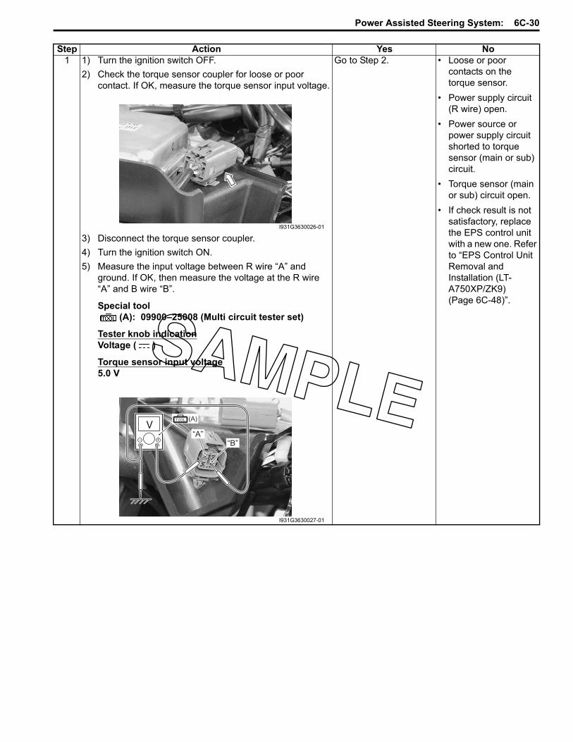
Power Assisted Steering System: 6C-30
Step Action Yes No1 1) Turn the ignition switch OFF.
2) Check the torque sensor coupler for loose or poor contact. If OK, measure the torque sensor input voltage.
3) Disconnect the torque sensor coupler.4) Turn the ignition switch ON.5) Measure the input voltage between R wire “A” and
ground. If OK, then measure the voltage at the R wire “A” and B wire “B”.
Special tool(A): 09900–25008 (Multi circuit tester set)
Tester knob indicationVoltage ( )
Torque sensor input voltage5.0 V
Go to Step 2. • Loose or poor contacts on the torque sensor.
• Power supply circuit (R wire) open.
• Power source or power supply circuit shorted to torque sensor (main or sub) circuit.
• Torque sensor (main or sub) circuit open.
• If check result is not satisfactory, replace the EPS control unit with a new one. Refer to “EPS Control Unit Removal and Installation (LT-A750XP/ZK9) (Page 6C-48)”.
I931G3630026-01
“A”“B”
(A)
I931G3630027-01
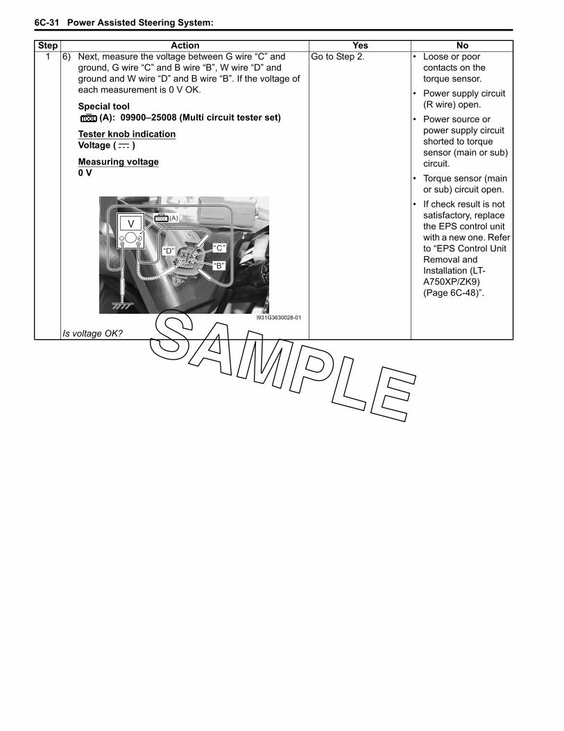
6C-31 Power Assisted Steering System:
1 6) Next, measure the voltage between G wire “C” and ground, G wire “C” and B wire “B”, W wire “D” and ground and W wire “D” and B wire “B”. If the voltage of each measurement is 0 V OK.
Special tool(A): 09900–25008 (Multi circuit tester set)
Tester knob indicationVoltage ( )
Measuring voltage0 V
Is voltage OK?
Go to Step 2. • Loose or poor contacts on the torque sensor.
• Power supply circuit (R wire) open.
• Power source or power supply circuit shorted to torque sensor (main or sub) circuit.
• Torque sensor (main or sub) circuit open.
• If check result is not satisfactory, replace the EPS control unit with a new one. Refer to “EPS Control Unit Removal and Installation (LT-A750XP/ZK9) (Page 6C-48)”.
Step Action Yes No
(A)
“C”
“B”
“D”
I931G3630028-01
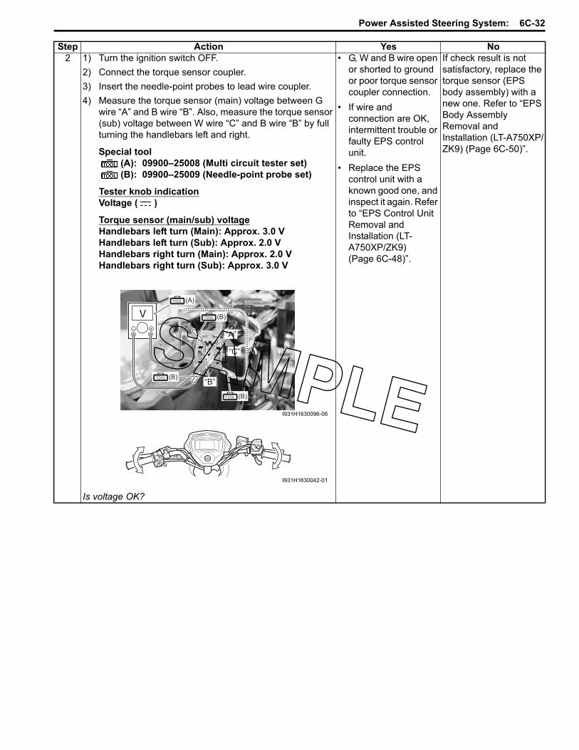
Power Assisted Steering System: 6C-32
2 1) Turn the ignition switch OFF.2) Connect the torque sensor coupler.3) Insert the needle-point probes to lead wire coupler.4) Measure the torque sensor (main) voltage between G
wire “A” and B wire “B”. Also, measure the torque sensor (sub) voltage between W wire “C” and B wire “B” by full turning the handlebars left and right.
Special tool(A): 09900–25008 (Multi circuit tester set)(B): 09900–25009 (Needle-point probe set)
Tester knob indicationVoltage ( )
Torque sensor (main/sub) voltageHandlebars left turn (Main): Approx. 3.0 VHandlebars left turn (Sub): Approx. 2.0 VHandlebars right turn (Main): Approx. 2.0 VHandlebars right turn (Sub): Approx. 3.0 V
Is voltage OK?
• G, W and B wire open or shorted to ground or poor torque sensor coupler connection.
• If wire and connection are OK, intermittent trouble or faulty EPS control unit.
• Replace the EPS control unit with a known good one, and inspect it again. Refer to “EPS Control Unit Removal and Installation (LT-A750XP/ZK9) (Page 6C-48)”.
If check result is not satisfactory, replace the torque sensor (EPS body assembly) with a new one. Refer to “EPS Body Assembly Removal and Installation (LT-A750XP/ZK9) (Page 6C-50)”.
Step Action Yes No
(B)
“A”
“B”
(A)
“C”
(B)
(B)
I931H1630096-06
I931H1630042-01

6C-33 Power Assisted Steering System:
DTC “C1114”: Torque Sensor Power Supply Circuit Malfunction (LT-A750XP/ZK9)B931G36304010
Troubleshooting
CAUTION!
Never remove the torque sensor to prevent accident and damage.
NOTEAfter repairing the trouble, clear the DTC using a SDS tool or mode coupler switch. Refer to “DTC (Diagnostic Trouble Code) Deleting (LT-A750XP/ZK9) (Page 6C-21)”.
Possible Cause• Faulty torque sensor signal circuit.• Faulty torque sensor.• Faulty EPS control unit.
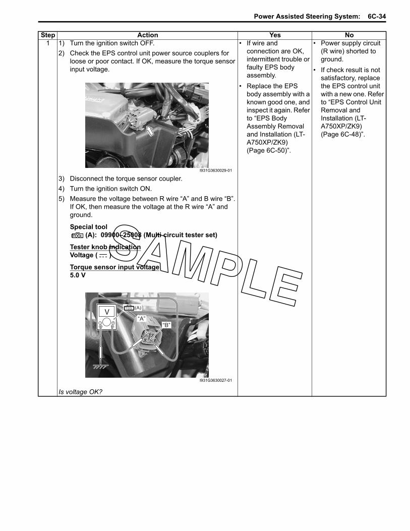
Power Assisted Steering System: 6C-34
Step Action Yes No1 1) Turn the ignition switch OFF.
2) Check the EPS control unit power source couplers for loose or poor contact. If OK, measure the torque sensor input voltage.
3) Disconnect the torque sensor coupler.4) Turn the ignition switch ON.5) Measure the voltage between R wire “A” and B wire “B”.
If OK, then measure the voltage at the R wire “A” and ground.
Special tool(A): 09900–25008 (Multi circuit tester set)
Tester knob indicationVoltage ( )
Torque sensor input voltage5.0 V
Is voltage OK?
• If wire and connection are OK, intermittent trouble or faulty EPS body assembly.
• Replace the EPS body assembly with a known good one, and inspect it again. Refer to “EPS Body Assembly Removal and Installation (LT-A750XP/ZK9) (Page 6C-50)”.
• Power supply circuit (R wire) shorted to ground.
• If check result is not satisfactory, replace the EPS control unit with a new one. Refer to “EPS Control Unit Removal and Installation (LT-A750XP/ZK9) (Page 6C-48)”.
I931G3630029-01
“A”“B”
(A)
I931G3630027-01

6C-35 Power Assisted Steering System:
DTC “C1115”: Torque Sensor (Sub) Circuit Malfunction (LT-A750XP/ZK9)B931G36304011
Troubleshooting
CAUTION!
Never remove the torque sensor to prevent accident and damage.
NOTEAfter repairing the trouble, clear the DTC using a SDS tool or mode coupler switch. Refer to “DTC (Diagnostic Trouble Code) Deleting (LT-A750XP/ZK9) (Page 6C-21)”.
Possible Cause• Faulty torque sensor signal circuit.• Faulty torque sensor.• Faulty EPS control unit.

Power Assisted Steering System: 6C-36
Step Action Yes No1 1) Turn the ignition switch OFF.
2) Check the torque sensor coupler for loose or poor contact. If OK, measure the torque sensor input voltage.
3) Disconnect the torque sensor coupler.4) Turn the ignition switch ON.5) Measure the input voltage between R wire “A” and
ground. If OK, then measure the input voltage between R wire “A” and B wire “B”.
Special tool(A): 09900–25008 (Multi circuit tester set)(B): 09900–25009 (Needle-point probe set)
Tester knob indicationVoltage ( )
Torque sensor input voltage5.0 V
Is voltage OK?
Go to step 2. • Loose or poor contacts on the torque sensor.
• Power supply circuit (R wire) or ground circuit (B wire) open.
• If check result is not satisfactory, replace the EPS control unit with a new one. Refer to “EPS Control Unit Removal and Installation (LT-A750XP/ZK9) (Page 6C-48)”.I931G3630026-01
(A)
“A”
“B”
(B)
(B)
I931G3630032-01

6C-37 Power Assisted Steering System:
2 1) Turn the ignition switch OFF.2) Connect the torque sensor coupler.3) Insert the needle-point probes to lead wire coupler.4) Turn the ignition switch ON.5) Measure the voltage between W wire “A” and B wire “B”
by turning the handlebars left and right.
Special tool(A): 09900–25008 (Multi circuit tester set)(B): 09900–25009 (Needle-point probe set)
Tester knob indicationVoltage ( )
Torque sensor (Sub) voltageHandlebars is left turn: Approx. 2.0 VHandlebars is right turn: Approx 3.0 V
Is voltage OK?
• Replace the EPS control unit with a known good one, and inspect it again. Refer to “EPS Control Unit Removal and Installation (LT-A750XP/ZK9) (Page 6C-48)”.
• R wire terminal or W wire terminal circuit open (torque sensor side).
• If check result is not satisfactory, replace the torque sensor (EPS body assembly) with a new one. Refer to “Steering Shaft Removal and Installation in Section 6B in related manual”.
Step Action Yes No
(B)
“A”
“B”
(A)
“C”
(B)
(B)
I931G3630030-02
I931H1630042-01

Power Assisted Steering System: 6C-38
DTC “C1121”: Vehicle Speed Signal Circuit Malfunction (LT-A750XP/ZK9)B931G36304012
Troubleshooting
NOTEAfter repairing the trouble, clear the DTC using a SDS tool or mode coupler switch. Refer to “DTC (Diagnostic Trouble Code) Deleting (LT-A750XP/ZK9) (Page 6C-21)”.
Possible Cause• Faulty vehicle speed signal circuit.• Faulty speed sensor.• Faulty EPS control unit.
Step Action Yes No1 1) Turn the ignition switch OFF.
2) Check the EPS control unit connector for loose or poor contact. If OK, then check the vehicle speed signal lead wire continuity.
Go to step 2. Bl/B wire open.
I931G3630031-01

6C-39 Power Assisted Steering System:
1 3) Disconnect the EPS control unit coupler [B], speed sensor coupler [C] and combination meter coupler [A]. Refer to “Speed Sensor Removal and Installation in Section 9C in related manual” and “Combination Meter Removal and Installation in Section 9C in related manual”.
4) Check the continuity between the Bl/B wire of EPS control unit coupler [B] and Bl/B wire of speed sensor [C]. Also, check the continuity between the Bl/B wire of EPS control unit coupler [B] and Bl/B wire of combination meter [A].
Special tool(A): 09900–25008 (Multi circuit tester set)(B): 09900–25009 (Needle-point probe set)
Tester knob indicationContinuity ( )
Is continuity OK?
Go to step 2. Bl/B wire open.Step Action Yes No
(A)
[A][B]
[C]“C”
“A”
(B)
“B”
(B)
I931H1630050-03

Power Assisted Steering System: 6C-40
2 1) Connect the combination meter coupler and speed sensor coupler.
2) Turn the ignition switch ON.3) Measure the voltage between the Bl/B wire “A” and
ground.
Special tool(A): 09900–25008 (Multi circuit tester set)
Tester knob indicationVoltage ( )
Vehicle speed signal voltage5.0 V
Is voltage OK?
Go to step 3. Bl/B wire shorted to ground.
3 1) Remove the engine side cover. Refer to “Rear Side Exterior Parts Removal and Installation in Section 9D in related manual”.
2) Inspect the speed sensor. Refer to “Speed Sensor Inspection in Section 9C in related manual”.
Is speed sensor OK?
Replace the EPS control unit. Refer to “EPS Control Unit Removal and Installation (LT-A750XP/ZK9) (Page 6C-48)”.
Replace the speed sensor. Refer to “Speed Sensor Removal and Installation in Section 9C in related manual”.
Step Action Yes No
“A”
(A)
I931G3630033-01
I931G3630034-01
6C-41 Power Assisted Steering System:
DTC “C1122”: Engine Speed Signal Circuit Malfunction (LT-A750XP/ZK9)B931G36304013
Troubleshooting
NOTEStart the engine after repairing the DTC and check that the indicator light is turned OFF. Refer to “Precautions in Diagnosing Troubles (LT-A750XP/ZK9) (Page 6C-1)”.
Possible Cause• Faulty engine speed signal circuit.• Faulty ECM.• Faulty EPS control unit.
Step Action Yes No1 1) Setup the SDS tool (Refer to the SDS operation manual
for further details.) or connect the mode select switch.2) Click “Engine” and check the DTC code.
Is not DTC “C12 (P0335)” displayed?
Go to step 2. Inspect the CKP sensor. Refer to “DTC “C12” (P0335): CKP Sensor Circuit Malfunction in Section 1A in related manual”.

Power Assisted Steering System: 6C-42
2 1) Turn the ignition switch OFF.2) Check the EPS control unit coupler for loose or poor
contact. If OK, then measure the engine speed signal lead wire continuity.
3) Disconnect the EPS control unit coupler and ECM coupler.
4) Check the continuity between the W wire “A” and terminal “31”.
Special tool(A): 09900–25008 (Multi circuit tester set)(B): 09900–25009 (Needle-point probe set)
Tester knob indicationContinuity ( )
Is continuity OK?
Go to step 3. W wire open.Step Action Yes No
I931G3630031-01
“B”
(A)
“31”
(B)
I931H1630052-02

6C-43 Power Assisted Steering System:
3 1) Connect the ECM coupler.2) Start the engine.3) Measure the voltage between W wire “A” and ground.
Special tool(A): 09900–25008 (Multi circuit tester set)
Tester knob indicationVoltage ( )
Engine speed signal voltageIt changes between 0 – 12 V
Is voltage OK?
Replace the EPS control unit with a new one. Refer to “EPS Control Unit Removal and Installation (LT-A750XP/ZK9) (Page 6C-48)”.
Replace the ECM with a new one. Refer to “EPS Control Unit Removal and Installation (LT-A750XP/ZK9) (Page 6C-48)”.
Step Action Yes No
“A” (A)
I931G3630035-01

Power Assisted Steering System: 6C-44
DTC “C1141”, “C1142”, “C1143”, “C1145” EPS Motor Circuit Malfunction (LT-A750XP/ZK9)B931G36304014
Troubleshooting
Possible Cause• Faulty EPS motor circuit.• Faulty EPS motor.• EPS control unit malfunction.
Step Action Yes No1 1) Turn the ignition switch OFF.
2) Check the EPS motor coupler for loose or poor contact. If OK, measure the EPS motor voltage.
3) Insert the needle-point probes to lead wire coupler.4) Start the engine and turn the handlebars left turn.5) Measure the voltage between R wire “A” and B wire “B”.
Special tool(A): 09900–25008 (Multi circuit tester set)(B): 09900–25009 (Needle-point probe set)
Tester knob indicationVoltage ( )
EPS motor voltageApprox. 7.0 V
Is voltage OK?
Go to step 2. R wire or B wire open or R wire shorted to ground.
I931G3630036-01
I931H1630093-01
(A)
(B)
I931G3630037-01

6C-45 Power Assisted Steering System:
2 1) Turn the ignition switch OFF.2) Disconnect the EPS motor coupler.
3) Inspect the continuity of the EPS motor. Refer to “EPS Motor Inspection (LT-A750XP/ZK9) (Page 6C-53)”.
Is continuity OK?
Replace the EPS control unit with a known good one, and inspect it again. Refer to “EPS Control Unit Removal and Installation (LT-A750XP/ZK9) (Page 6C-48)”.
Replace the EPS motor (EPS body assembly) with a new one. Refer to “EPS Body Assembly Removal and Installation (LT-A750XP/ZK9) (Page 6C-50)”.
Step Action Yes No
I931G3630038-01

Power Assisted Steering System: 6C-46
DTC “C1153” EPS Control Unit Supply Voltage Circuit Malfunction (LT-A750XP/ZK9)B931G36304015
Troubleshooting
Possible Cause• Faulty regulator/rectifier.• Faulty EPS control unit.• Faulty wire harness, etc.
Step Action Yes No1 1) Remove the seat. Refer to “Seat Removal and
Installation in Section 9D in related manual”.2) Measure the voltage between the (+) and (–) battery
terminals using the multi circuit tester.
Special tool(A): 09900–25008 (Multi circuit tester set)
Tester knob indicationVoltage ( )
Battery voltage12.0 V and more
Is the voltage over 12 V?
Go to Step 2. Charge or replace the battery.
2 1) Start the engine at 5 000 r/min with the dimmer switch set to HI.
2) Measure the voltage between the (+) and (–) battery terminals.
Special tool: 09900–25008 (Multi circuit tester set)
Tester knob indicationVoltage ( )
Regulated voltage13.5 – 15.0 V at 5 000 r/min
Is the voltage 13.5 – 15.0 V?
Go to Step 3. Inspect the regulator/rectifier. Refer to “Regulator / Rectifier Inspection in Section 1J in related manual”.
(A)
I931G3630039-01

6C-47 Power Assisted Steering System:
DTC “C1152”, “C1154”, “C1155” EPS Control Unit Malfunction (LT-A750XP/ZK9)B931G36304016
Troubleshooting• Replace the EPS control unit. Refer to “EPS Control Unit Removal and Installation (LT-A750XP/ZK9) (Page 6C-
48)”.
3 1) Turn the ignition switch OFF.2) Check the EPS control unit coupler for loose or poor
contacts. If OK, then disconnect the EPS control unit coupler.
3) Start the engine at 5 000 r/min with the dimmer switch set to HI.
4) Measure the voltage between terminal “A” and terminal “B” at the coupler.
Special tool(A): 09900–25008 (Multi circuit tester set)
Tester knob indicationVoltage ( )
Is the voltage same as Step 2?
Replace the EPS control unit.
Inspect the wire harness. (Faulty ignition or ground wire)
Step Action Yes No
“A” “B”
(A) (A)
( ) (–)
I931G3630040-01
Possible CauseC1152 • Relay welding (EPS control unit internal circuit)C1154 • Relay malfunction (EPS control unit internal circuit)C1155 • EPS control unit malfunction

Power Assisted Steering System: 6C-48
Repair InstructionsEPS Control Unit Construction (LT-A750XP/ZK9)
B931G36306001
EPS Control Unit Removal and Installation (LT-A750XP/ZK9)
B931G36306002Removal1) Disconnect the battery (–) lead wire. Refer to
“Battery Removal and Installation (LT-A750XP/ZK9) in Section 1J (Page 1J-2)”.
2) Remove the front fender. Refer to “Front Side Exterior Parts Removal and Installation in Section 9D in related manual”.
3) Disconnect the EPS control unit couplers.
1
2
33
“B”
4
“A”
(a)
FWDFWD
I931H1630056-02
1. EPS control unit 4. Torque sensor coupler2. EPS control unit plate : 12 N⋅m (1.2 kgf-m, 8.5 lbf-ft)3. Cushion “B”: Install the clip of the torque sensor coupler to the hole “A” of the
EPS control unit plate.
I931G3630041-01

6C-49 Power Assisted Steering System:
4) Disconnect the torque sensor coupler (1).
5) Remove the clamp (2) and release the EPS motor lead wire (3).
6) Release the clip part “A” of the EPS control unit plate with the special tool.
Special tool(A): 09942–83110 (Clip remover)
7) Remove the fastener (4) and bolt (5).8) Remove the EPS control unit (6) along with the EPS
control unit plate (7).
9) Remove the EPS control unit (6) from the EPS control unit plate (7) as shown in the EPS control unit construction. Refer to “EPS Control Unit Construction (LT-A750XP/ZK9) (Page 6C-48)”.
InstallationInstall the EPS control unit in the reverse order of removal. Pay attention to the following points:• Tighten the EPS control unit mounting nut (1) to the
specified torque.
Tightening torqueEPS control unit mounting nut (a): 12 N·m (1.2 kgf-m, 8.5 lbf-ft)
• Connect the torque sensor lead wire (2).
1
I931G3630042-01
2
3
I931G3630043-01
(A)
“A”
I931G3630044-01
6
7
5
4
I931G3630045-01
(a)1
I931G3630046-01
2
I931G3630047-01

Power Assisted Steering System: 6C-50
• Connect the EPS motor coupler (3) and clamp (4).• Connect the other EPS control unit couplers.
• Install the front fender. Refer to “Front Side Exterior Parts Removal and Installation in Section 9D in related manual”.
EPS Body Assembly Components (LT-A750XP/ZK9)
B931G36306003Refer to “Steering / Handlebars Components (LT-A750XP/ZK9) in Section 6B (Page 6B-1)”.
EPS Body Assembly Removal and Installation (LT-A750XP/ZK9)
B931G36306004Refer to “Steering / Handlebars Components (LT-A750XP/ZK9) in Section 6B (Page 6B-1)”.Refer to “Steering / Handlebars Assembly Construction (LT-A750XP/ZK9) in Section 6B (Page 6B-2)”.
Removal1) Remove the handlebars. Refer to “Handlebars
Removal and Installation (LT-A750XP/ZK9) in Section 6B (Page 6B-3)”.
2) Remove the combination meter. Refer to “Combination Meter Removal and Installation in Section 9C in related manual”.
3) Remove the front fender. Refer to “Front Side Exterior Parts Removal and Installation in Section 9D in related manual”.
4) Remove the auxiliary headlight (1). Refer to “Auxiliary Headlight Removal and Installation in Section 9B in related manual”.
5) Remove the center cover (2).
6) Remove the handlebar holder (3) by removing the nuts (4).
7) Remove the steering shaft upper nut (5).
8) Remove the steering shaft plate (6) with the special tool.
Special tool(A): 09944–36011 (Steering wheel remover)
34
I931G3630048-01
1
I931G3630049-01
2
I931G3630050-01
4
3
I931G3630051-01
5
I931G3630068-01
(A)
6
I931G3630052-01

6C-51 Power Assisted Steering System:
9) Remove the front brake hose union (7) and throttle cable (8) from the cable guide (9).
10) Remove the steering shaft bolt (10).
11) Remove the EPS body assembly mounting nuts and bolts.
12) Remove the cable guide (11).
13) Remove the EPS body assembly.
CAUTION!
Never disassemble the EPS body assembly.
InstallationRefer to “Steering / Handlebars Assembly Construction (LT-A750XP/ZK9) in Section 6B (Page 6B-2)”.Install the EPS body assembly in the reverse order of removal. Pay attention to the following points:• Apply grease to the spline of the EPS body assembly.
: Grease 99000–25160 (Water resistance grease or equivalent)
• When installing the EPS body assembly, align the marking “A” of the EPS output shaft and slide “B” of the steering shaft.
7
9
8
I931G3630053-01
10
I931G3630054-01
I931G3630055-01
11
I931G3630056-01
I931G3630057-02
“A”
“B”
I931G3630058-02

Power Assisted Steering System: 6C-52
• Install the cable guide (1) and tighten the bolts (2) to the specified torque.
Tightening torqueEPS body assembly mounting bolt (a): 26 N·m (2.6 kgf-m, 19.0 lbf-ft)
• Tighten the EPS body assembly mounting nuts (3) to the specified torque.
Tightening torqueEPS body assembly mounting nut (b): 28 N·m (2.8 kgf-m, 20.0 lbf-ft)
• Apply thread lock to the steering shaft bolt (4) and tighten it to the specified torque.
: Thread lock cement 99000–32030 (THREAD LOCK CEMENT SUPER “1303” or equivalent)
Tightening torqueSteering shaft bolt (c): 26 N·m (2.6 kgf-m, 19.0 lbf-ft)
• Install the front brake hose union (5) and throttle cable (6) to the cable guide.
• Apply grease to the spline of the EPS body assembly.
: Grease 99000–25160 (Water resistance grease or equivalent)
• Install the steering shaft plate (7) and tighten the steering shaft upper nut to the specified torque.
CAUTION!
• Never use an impact wrench when tightening the steering shaft upper nut.
• Never exceed the specified torque to prevent EPS body assembly damage.
Tightening torqueSteering shaft upper nut (d): 120 N·m (12.0 kgf-m, 87.0 lbf-ft)
(a)21
I931G3630059-02
(b)3
I931G3630060-02
(c)4
I931G3630061-03
5 6
I931G3630062-02
(d)
7
I931G3630072-01

6C-53 Power Assisted Steering System:
• Install the handlebar holder (8) and tighten the nuts to the specified torque.
Tightening torqueHandlebar holder nut (e): 60 N·m (6.0 kgf-m, 43.5 lbf-ft)
• Install the center cover (9).
• Install the auxiliary headlight. Refer to “Auxiliary Headlight Removal and Installation in Section 9B in related manual”.
• Install the front fender. Refer to “Front Side Exterior Parts Removal and Installation in Section 9D in related manual”.
• Install the handlebars. Refer to “Handlebars Removal and Installation (LT-A750XP/ZK9) in Section 6B (Page 6B-3)”.
• Install the combination meter. Refer to “Combination Meter Removal and Installation in Section 9C in related manual”.
EPS Motor Inspection (LT-A750XP/ZK9)B931G36306005
1) Disconnect the EPS motor coupler.2) First, check for insulation with the tester between
terminals “A” and “B”.If continuity does not exist, replace the EPS body assembly with a new one.
Special tool(A): 09900–25008 (Multi circuit tester set)
Tester knob indicationContinuity ( )
3) Next, check for insulation with the tester between terminal “A” and body ground “C” and terminal “B” and body ground “C”.If continuity is found, replace the EPS body assembly with a new one.
Special tool(A): 09900–25008 (Multi circuit tester set)
Tester knob indicationContinuity ( )
9. Center cover10. Wiring harness (Left handlebar switch/Parking rear brake switch/
Parking rear brake light switch), (Emergency switch (For P-17) and horn switch (For P-17, 24))
11. Parking/Rear brake cable12. Steering shaft“A”: Hooked point
8
(e)
I931G3630063-02
11
1110
“A”9
I931G3630064-02
“A”“B”
(A)
I931H1630107-02
“A”
“C”
“B”
(A)
I931H1630108-02

Power Assisted Steering System: 6C-54
SpecificationsTightening Torque Specifications
B931G36307001
NOTEThe specified tightening torque is described in the following.“EPS Control Unit Construction (LT-A750XP/ZK9) (Page 6C-48)”
Reference:For the tightening torque of fastener not specified in this section, refer to “Tightening Torque List (LT-A750XP/ZK9) in Section 0C (Page 0C-7)”.
Special Tools and EquipmentRecommended Service Material
B931G36308001
Fastening part Tightening torque NoteN⋅m kgf-m lbf-ftEPS control unit mounting nut 12 1.2 8.5 (Page 6C-49)EPS body assembly mounting bolt 26 2.6 19.0 (Page 6C-52)EPS body assembly mounting nut 28 2.8 20.0 (Page 6C-52)Steering shaft bolt 26 2.6 19.0 (Page 6C-52)Steering shaft upper nut 120 12.0 87.0 (Page 6C-52)Handlebar holder nut 60 6.0 43.5 (Page 6C-53)
Material SUZUKI recommended product or Specification NoteGrease Water resistance grease or
equivalentP/No.: 99000–25160 (Page 6C-51) /
(Page 6C-52)Thread lock cement THREAD LOCK CEMENT SUPER
“1303” or equivalentP/No.: 99000–32030 (Page 6C-52)
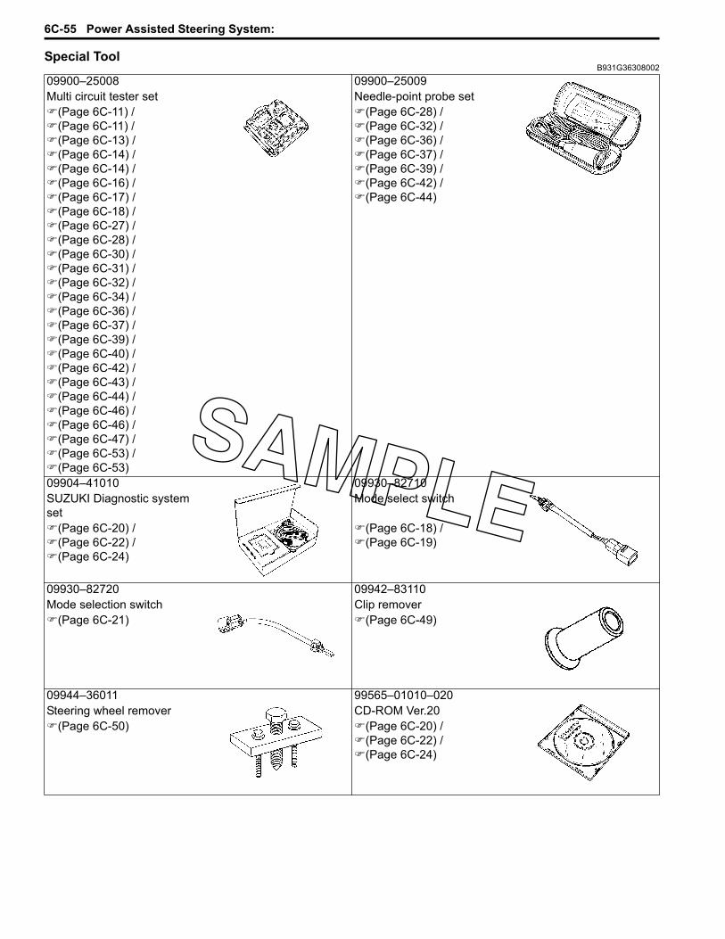
6C-55 Power Assisted Steering System:
Special ToolB931G36308002
09900–25008 09900–25009Multi circuit tester set Needle-point probe set
(Page 6C-11) / (Page 6C-11) / (Page 6C-13) / (Page 6C-14) / (Page 6C-14) / (Page 6C-16) / (Page 6C-17) / (Page 6C-18) / (Page 6C-27) / (Page 6C-28) / (Page 6C-30) / (Page 6C-31) / (Page 6C-32) / (Page 6C-34) / (Page 6C-36) / (Page 6C-37) / (Page 6C-39) / (Page 6C-40) / (Page 6C-42) / (Page 6C-43) / (Page 6C-44) / (Page 6C-46) / (Page 6C-46) / (Page 6C-47) / (Page 6C-53) / (Page 6C-53)
(Page 6C-28) / (Page 6C-32) / (Page 6C-36) / (Page 6C-37) / (Page 6C-39) / (Page 6C-42) / (Page 6C-44)
09904–41010 09930–82710SUZUKI Diagnostic system set
Mode select switch
(Page 6C-20) / (Page 6C-22) / (Page 6C-24)
(Page 6C-18) / (Page 6C-19)
09930–82720 09942–83110Mode selection switch Clip remover
(Page 6C-21) (Page 6C-49)
09944–36011 99565–01010–020Steering wheel remover CD-ROM Ver.20
(Page 6C-50) (Page 6C-20) / (Page 6C-22) / (Page 6C-24)

Table of Contents 9- i
9
Section 9
CONTENTS
Body and Accessories
NOTEFor the items with asterisk (*) in the “CONTENTS” below, refer to the same section of the service manual mentioned in the “FOREWORD” of this manual.
Precautions ................................................. 9-*Precautions..............................................................9-*
Precautions for Electrical System ..........................9-*Component Location ..............................................9-*
Electrical Components Location ............................9-*
Wiring Systems........................................ 9A-1Schematic and Routing Diagram........................9A-1
Wiring Diagram ....................................................9A-*Wiring Harness Routing Diagram.........................9A-*Wiring Diagram (LT-A750XP/ZK9)......................9A-1Wiring Harness Routing Diagram (LT-
A750XP/ZK9) ....................................................9A-4Specifications.......................................................9A-7
Service Data ........................................................9A-*Tightening Torque Specifications........................9A-7
Lighting Systems......................................9B-*Repair Instructions .............................................. 9B-*
Headlight Components ........................................9B-*Headlight Removal and Installation .....................9B-*Headlight Bulb Replacement ...............................9B-*Headlight Beam Adjustment ................................9B-*Auxiliary Headlight Components..........................9B-*Auxiliary Headlight Removal and Installation.......9B-*Auxiliary Headlight Bulb Replacement .................9B-*Auxiliary Headlight Beam Adjustment ..................9B-*Rear Combination Light components...................9B-*Rear Combination Light Removal and
Installation..........................................................9B-*Rear Combination Light Bulb Replacement .........9B-*Reversing Light Bulb Replacement (For P-17) .....9B-*Reversing Light Relay Inspection (For P-17) .......9B-*Dimmer Switch Inspection....................................9B-*
Specifications....................................................... 9B-*Service Data ........................................................9B-*
Special Tools and Equipment ............................. 9B-*Special Tool .........................................................9B-*
Combination Meter / Fuel Meter / Horn...9C-*General Description ............................................. 9C-*
Combination Meter System Description.............. 9C-*Repair Instructions .............................................. 9C-*
Combination Meter Components ........................ 9C-*
Combination Meter Removal and Installation ..... 9C-*Combination Meter Disassembly and
Assembly........................................................... 9C-*Combination Meter Inspection ............................ 9C-*Engine Coolant Temperature Indicator Light
Inspection.......................................................... 9C-*Engine Coolant Temperature Removal and
Installation ......................................................... 9C-*Fuel Level Indicator Inspection ........................... 9C-*Fuel Level Gauge Inspection .............................. 9C-*Speedometer Inspection ..................................... 9C-*Speed Sensor Removal and Installation ............. 9C-*Speed Sensor Inspection .................................... 9C-*Ignition Switch Inspection.................................... 9C-*Ignition Switch Removal and Installation............. 9C-*Horn Inspection (For P-17, 24)............................ 9C-*Horn Removal and Installation (For P-17, 24)..... 9C-*
Specifications....................................................... 9C-*Service Data........................................................ 9C-*Tightening Torque Specifications........................ 9C-*
Special Tools and Equipment ............................. 9C-*Recommended Service Material ......................... 9C-*Special Tool ........................................................ 9C-*
Exterior Parts ............................................9D-*Repair Instructions .............................................. 9D-*
Exterior Parts Construction ................................. 9D-*Rear Fender Heat Shield Construction ............... 9D-*Fuel Tank Lower Cover Heat Shield
Installation ......................................................... 9D-*Fastener Removal and Installation...................... 9D-*Front Side Exterior Parts Removal and
Installation ......................................................... 9D-*Rear Side Exterior Parts Removal and
Installation ......................................................... 9D-*Seat Removal and Installation ............................ 9D-*Under Cover Components .................................. 9D-*Under Cover Removal and Installation ............... 9D-*
Body Structure......................................... 9E-1Repair Instructions ..............................................9E-1
Body Frame Construction ................................... 9E-*Footrest Construction.......................................... 9E-*Footrest Removal and Installation....................... 9E-*Carrier Construction ............................................ 9E-*

9-ii Table of Contents
Front Carrier Removal and Installation ............... 9E-*Rear Carrier Removal and Installation ................ 9E-*Front Grip Bar Construction ................................ 9E-*Front Grip Bar Removal and Installation ............. 9E-*Trailer Towing Construction ................................ 9E-*Trailer Towing Removal and Instruction.............. 9E-*
Body Frame Construction (LT-A750XP/ZK9)......9E-1Specifications....................................................... 9E-*
Tightening Torque Specifications........................ 9E-*Special Tools and Equipment .............................9E-1
Recommended Service Material .........................9E-1

Wiring Systems: 9A-1
Body and AccessoriesWiring SystemsSchematic and Routing Diagram
Wiring Diagram (LT-A750XP/ZK9)B931G39102003
Refer to “Wire Color Symbols in Section 0A in related manual”.

9A-2 Wiring Systems:
For P-17
ON
OFF
HO
RN
HE
AD
LIG
HT
(L)
SP
EE
DO
ME
TE
R
BR
AK
EL
EV
ER
SW
ITC
H(L
)
RE
AR
BR
AK
ES
WIT
CH
BA
CK
UP
LIG
HT
EC
M
RE
AR
CO
MB
INA
TIO
NL
IGH
T
ON
OFF
PUSH
BR
AK
EL
EV
ER
SW
ITC
HSE
T
SECE
DE
EM
ER
GE
NC
YS
WIT
CH
HO
RN
BU
TT
ON
AU
XIL
IAR
YH
EA
DL
IGH
T
HE
AD
LIG
HT
(R)
HI
LO
RU
N
OFF
PUSH
DIM
ME
RS
WIT
CH
EN
GIN
ES
TO
PS
WIT
CH
OV
ER
RID
ES
WIT
CH
STA
RT
BU
TT
ON
PUSH
LOW
PO
SITI
ON
DIO
DE
HIG
HPO
SITI
ON
DIO
DE
4W
D/
DIF
F-L
OC
KR
EL
AY
PO
WE
RS
OU
RC
EM
RE
GU
LA
TO
R/
RE
CT
IFIE
RF
UE
LP
UM
P
FU
EL
PU
MP
RE
LA
Y
IGN
ITIO
NC
OIL
SP
EE
DS
EN
SO
RT
OS
EN
SO
R
BA
CK
UP
LIG
HT
RE
LA
YB
AC
K B
UZ
ZE
R1
STA
RT
ER
M
OT
OR
STA
RT
ER
R
EL
AY
1:
MA
IN (
30
A)
BA
TT
ER
Y
EP
S C
ON
TR
OL
UN
ITC
KP
SE
NS
OR G
EN
ER
AT
OR
P
EC
TS
EN
SO
RIA
TS
EN
SO
R
IAP
SE
NS
OR
TP
SE
NS
OR
RE
SIS
TO
R
PA
RK
ING
BR
AK
ER
EL
AY
NE
UT
RA
LR
EL
AY
DIO
DE
12
3
45
6
FU
SE
BO
X
4W
D/
DIF
F-L
OC
KD
IOD
E
INJE
CT
OR
ISC
VA
LV
E
1. H
EA
D H
I2. H
EA
D L
O3. F
UE
L4. IG
NIT
ION
5. FA
N6. P
OW
ER
SO
UR
CE
10 A
10 A
10 A
15 A
15 A
10 A
2WD
4WD
LOC
K
GE
AR
PO
SIT
ION
SW
ITC
H
4W
D/D
IFF
-LO
CK
SW
ITC
H4W
D/D
IFF
-LO
CK
AC
TU
AT
OR
ON
OFF
ON
OFF
ON
3
ON
2
ON
1
OFF
CO
OL
ING
FA
NT
HE
RM
O-
SW
ITC
H
CO
OL
ING
FA
NM
OT
OR
IGN
ITIO
NS
WIT
CH
PA
RK
ING
BR
AK
ES
WIT
CH
DIF
F-L
OC
KR
EL
AY
ON
OFF
B/WB/W
Bl/W Bl/WO/Y O/Y
W/B W/B
B/WB/W
O
Bl/R Bl/R
Bl Bl
R/G R/G
R
O/Y O/Y
R/B R/B
Bl/B Bl/B
W
W/R W/RB/Y B/Y
O/Y O/Y
B/WB/W
W/G W/G
B/G B/G
Y/B Y/B
O
B/W
Bl/W
O/Y O/Y
W/B
B/W
Bl/R
Bl
R/G
R
R/B
Bl/B
W
W/RB/Y
B/W
W/G
B/G
Y/B
GG
YY
YY
GG
O/Y
O
O/Y
O
O/Y
O/Y
B/WB/W
PB
B
B/WB/W
B/W
O/G O/G
PB
O
B
GG
B/W
O/G
O
O/Y
Bl/R
Bl/R
Gr
B/W
W/B
Gr
B/W
B/W
B/W
W/B
Gr
B/W
W/B
Gr
B/W
R BRRR
B
W/B
O/Y
YB
/W W YB
/W W
YB
/W W YB
/W W
YB
/W W YB
/W WYB
/W W YB
/W W
Y/Bl Y/BlW/Bl W/BlO/Bl O/Bl
OO/WO/WY/G Y/GB/WB/WBr Br BrBr Br Br
Gr Gr
W/R W/R
W/Y W/Y
W/G W/G
Gr GrW
Y
OO/WO/WY/G Y/GB/WB/W
Y/BlW/Bl
Y/GB/W
Gr
W/R
W/Y
W/G
GrW
Y
Y/GB/W
O/BlO
O/WO
O/W
YY
YRR
YY
Y
B/WB/W
R
Br/W Br/W
B/Br B/Br
R/B R/BBl/B Bl/B
B/WB/W
Y/R Y/R
B/WB/W
B/W
R
Br/W
B/Br
R/BBl/B
B/W
Y/B Y/B Y/B
BB
Y/R
B/W
O/Y O/Y
W/B W/B
O/Y O/Y
W/B W/B
B/WB/W
B/WB/W
W/B W/B
W/B
W/B
B/W
B/W
W/B
O/Y
O/Y
O/B O/B O/B
BY
B/WB/WO/Y O/Y
Bl BlBl/R Bl/R
B
B/W
Bl/R
Y
Bl
O/Y
O
W/B W/B
B
B
W/B
B
B
O
Y/Bl Y/Bl
O/WO/WO/W
R/B R/B
W/B W/B
Gr/W Gr/W
O/WO/W
R/B R/B
B/R B/R
R
B/WB/W
W/Y W/Y
Bl/G Bl/G
Br/W Br/W
B/Bl B/Bl
B
G/B G/B
Y
R/G R/G
GB/Lg B/Lg
B
Y/Bl Y/Bl
Y/R Y/R
Y/B Y/B
Gr/R Gr/R
B/G B/G
B/Br B/Br
Br Br
Bl/B Bl/B
W/R W/R
DgDg
B/Y B/Y
Y/R Y/R
Y/Bl
R/B
W/B
Gr/W
R/B
B/R
R
B/W
W/Y
Bl/G
Br/W
B/Bl
B
G/B
Y
R/G
G
B
Y/Bl
Y/R
Y/B
Gr/R
B/G
B/Br
Br
Bl/B
W/R
B/Y
Y/R
O/W
B/Lg
Dg
W/Bl W/Bl
P/WP/W
O/WO/W
W/R W/R
Gr/R Gr/R
B/WB/W
W/Bl
WW
P/W
W/R
Gr/R
B/W
O/W
B
Y/B Y/B
B/WB/W
RR
B/WB/W
B
Y/B
B/W
RR
R/B
B/W B/WB/WB/W
Bl/G Bl/G
BBl Bl
W
Y
YY
Bl/G
BBl
W
Y
YY
Y
YY
Y
YY
B/Bl B/Bl
B/Br B/Br
DgDg
B/Br B/Br
B/Br B/Br
G/B G/BR
R
Y
B/Br B/Br
B/R B/R
B/WB/W
B/Bl B/Bl
B/WB/W
B/Bl B/Bl
Bl/B Bl/B
B/Bl
B/Br
B/Br
B/Br
G/BR
R
W/Y W/Y W/Y
Gr Gr Gr
Y
B/Br
B/R
B/W
B/Bl
B/W
B/Bl
Bl/B
Dg
W/Bl W/BlW
Gr/W Gr/W
Y/R Y/R
B/Lg B/Lg
R/B R/B
P/WP/W
G
R/B R/B
W/Bl W/Bl
RWY
Y/Bl Y/Bl
W/Bl W/BlR/B R/B
O/Y O/YO
O/R O/R
O/B O/B
Y/G Y/GB/Bl B/Bl
O/Y O/Y
Y/B Y/B
W/BlW
Gr/W
Y/R
R/B
P/W
G
R/B
W/Bl
RWY
Y/Bl
W/BlR/B
Y/GB/Bl
Y/B
B/Lg
O/YO
O/R
O/B
O/Y
Bl/R Bl/R Bl/RO/Y O/YRR
O/Y O/Y
RR
B/WB/WB/W
O/Y
O/Y
O/Y
W
Bl/B
Y
Gr/R
W/R
R/B
B/W
Bl/R Bl/R
OO
BW/Bl W/Bl
Br Br
B/G B/GB/Y B/Y
B/WB/W
O
W
Br BrBr Br
R/G R/G
B/WB/W
YY
Bl/B Bl/B
Bl/R Bl/RW/R W/R
W/G W/GB/WB/W
O
Bl/R
BW/Bl
Br
B/GB/Y
B/W
W
BrBr
R/G
B/W
Bl/B
Bl/RW/R
W/GB/W
Bl Bl Bl
Bl Bl
RW
GB/WB/WB/W
Bl
RW
G
OO
W
Br BrGr GrG
B
Bl Bl
Y
W
BrGrG
B
Bl
Y
O/Y O/Y
B/R B/R B/R
O/Y
B/R B/R
O/R O/R
B/WB/W
B/R B/R
R
OO/Bl O/BlBl/W Bl/W
B/R
B/W
B/R
R
Bl/W
YY
OO/Bl
O/R
B
Bl Bl
R
OGr GrP
B
Bl
R
GrP
O/R O/R
O
O/R
O/Y O/Y
Y/B Y/B
B
B/G B/G
Y/B
B
B/G
O/Y
RRR
BB
I931G3910901-02

Wiring Systems: 9A-3
For P-24, 28, 33
ON
OFF
HO
RN
HE
AD
LIG
HT
(L)
SP
EE
DO
ME
TE
R
BR
AK
EL
EV
ER
SW
ITC
H(L
)
RE
AR
BR
AK
ES
WIT
CH
EC
M
RE
AR
CO
MB
INA
TIO
NL
IGH
T
OP
TIO
N
ON
OFF
PUSH
BR
AK
EL
EV
ER
SW
ITC
H
HO
RN
BU
TT
ON
AU
XIL
IAR
YH
EA
DL
IGH
T
HE
AD
LIG
HT
(R)
HI
LO
RU
N
OFF
PUSH
DIM
ME
RS
WIT
CH
EN
GIN
ES
TO
PS
WIT
CH
OV
ER
RID
ES
WIT
CH
STA
RT
BU
TT
ON
PUSH
LOW
PO
SITI
ON
DIO
DE
HIG
HPO
SITI
ON
DIO
DE
4W
D/
DIF
F-L
OC
KR
EL
AY
PO
WE
RS
OU
RC
EM
RE
GU
LA
TO
R/
RE
CT
IFIE
RF
UE
LP
UM
P
FU
EL
PU
MP
RE
LA
Y
IGN
ITIO
NC
OIL
SP
EE
DS
EN
SO
RT
OS
EN
SO
R
1
STA
RT
ER
M
OT
OR
STA
RT
ER
R
EL
AY
1:
MA
IN (
30
A)
BA
TT
ER
Y
EP
S C
ON
TO
L U
NT
CK
PS
EN
SO
R GE
NE
RA
TO
R
P
EC
TS
EN
SO
RIA
TS
EN
SO
R
IAP
SE
NS
OR
TP
SE
NS
OR
RE
SIS
TO
R
PA
RK
ING
BR
AK
ER
EL
AY
NE
UT
RA
LR
EL
AY
DIO
DE
12
3
45
6
FU
SE
BO
X
4W
D/
DIF
F-L
OC
KD
IOD
E
INJE
CT
OR
ISC
VA
LV
E
1. H
EA
D H
I2. H
EA
D L
O3. F
UE
L4. IG
NIT
ION
5. FA
N6. P
OW
ER
SO
UR
CE
10 A
10 A
10 A
15 A
15 A
10 A
2WD
4WD
LOC
K
GE
AR
PO
SIT
ION
SW
ITC
H
4W
D/D
IFF
-LO
CK
SW
ITC
H4W
D/D
IFF
-LO
CK
AC
TU
AT
OR
ON
OFF
ON
OFF
ON
3
ON
2
ON
1
OFF
CO
OL
ING
FA
NT
HE
RM
O-
SW
ITC
H
CO
OL
ING
FA
NM
OT
OR
IGN
ITIO
NS
WIT
CH
PA
RK
ING
BR
AK
ES
WIT
CH
DIF
F-L
OC
KR
EL
AY
ON
OFF
B/WB/W
Bl/W Bl/WO/Y O/Y
W/B W/B
B/WB/W
O
Bl/R Bl/R
Bl Bl
R/G R/G
R
O/Y O/Y
R/B R/B
Bl/B Bl/B
W
W/R W/RB/Y B/Y
O/Y O/Y
B/WB/W
W/G W/G
B/G B/G
Y/B Y/B
B/W
Bl/W
W/B
B/W
Bl/R
Bl
R/G
R
R/B
Bl/B
W
W/RB/Y
B/W
W/G
B/G
Y/B
GG
YY
GG
O/Y
O
O/Y
O/Y
B/WB/W
PB
B
B/WB/W
B/W
PB
B
GG
B/W
O/Y
Bl/R
Bl/R
Gr
B/W
W/B
Gr
B/W
W/B
Gr
B/W
W/B
Gr
B/W
W/B
O/Y
YB
/W W YB
/W WYB
/W W YB
/W W
YB
/W W YB
/W WYB
/W W YB
/W W
Y/Bl Y/BlW/Bl W/BlO/Bl O/Bl
O/WO/WY/G Y/GB/WB/WBr Br BrBr Br Br
Gr Gr
W/R W/R
W/Y W/Y
W/G W/G
Gr GrW
Y
OO/WO/WY/G Y/GB/WB/W
Y/BlW/Bl
Y/GB/W
Gr
W/R
W/Y
W/G
GrW
Y
Y/GB/W
O/BlO/Y O/Y O/YO/W
OO/W
YY
YRR
YY
Y
B/WB/W
R
Br/W Br/W
B/Br B/Br
R/B R/BBl/B Bl/B
B/WB/W
Y/R Y/R
B/WB/W
B/W
R
Br/W
B/Br
R/BBl/B
B/W
Y/B Y/B Y/B
BB
Y/R
B/W
O/Y O/Y
W/B W/B
O/Y O/Y
W/B W/B
B/WB/W
B/WB/W
W/B W/B
W/B
W/B
B/W
B/W
W/B
O/Y
O/Y
O/B O/B O/B
BY
B/WB/WO/Y O/Y
Bl BlBl/R Bl/R
B
B/W
Bl/R
Y
Bl
O/Y
O
W/B W/B
B
B
W/B
B
B
O
Y/Bl Y/Bl
O/WO/WO/W
R/B R/B
W/B W/B
Gr/W Gr/W
O/WO/W
R/B R/B
B/R B/R
R
B/WB/W
W/Y W/Y
Bl/G Bl/G
Br/W Br/W
B/Bl B/Bl
B
G/B G/B
Y
R/G R/G
GB/Lg B/Lg
B
Y/Bl Y/Bl
Y/R Y/R
Y/B Y/B
Gr/R Gr/R
B/G B/G
B/Br B/Br
Br Br
Bl/B Bl/B
W/R W/R
DgDg
B/Y B/Y
Y/R Y/R
Y/Bl
R/B
W/B
Gr/W
R/B
B/R
R
B/W
W/Y
Bl/G
Br/W
B/Bl
B
G/B
Y
R/G
G
B
Y/Bl
Y/R
Y/B
Gr/R
B/G
B/Br
Br
Bl/B
W/R
B/Y
Y/R
O/W
B/Lg
Dg
W/Bl W/Bl
P/WP/W
O/WO/W
W/R W/R
Gr/R Gr/R
B/WB/W
W/Bl
WW
P/W
W/R
Gr/R
B/W
O/W
B
Y/B Y/B
B/WB/W
RR
B/WB/W
B
Y/B
B/W
RR
R/B
B/W B/WB/WB/W
Bl/G Bl/G
BBl Bl
W
Y
YY
Bl/G
BBl
W
Y
YY
Y
YY
Y
YY
B/Bl B/Bl
B/Br B/Br
DgDg
B/Br B/Br
B/Br B/Br
G/B G/BR
R
Y
B/Br B/Br
B/R B/R
B/WB/W
B/Bl B/Bl
B/WB/W
B/Bl B/Bl
Bl/B Bl/B
B/Bl
B/Br
B/Br
B/Br
G/BR
R
W/Y W/Y W/Y
Gr Gr Gr
Y
B/Br
B/R
B/W
B/Bl
B/W
B/Bl
Bl/B
Dg
W/Bl W/BlW
Gr/W Gr/W
Y/R Y/R
B/Lg B/Lg
R/B R/B
P/WP/W
G
R/B R/B
W/Bl W/Bl
RWY
Y/Bl Y/Bl
W/Bl W/BlR/B R/B
O/Y O/YO
O/R O/R
O/B O/B
Y/G Y/GB/Bl B/Bl
O/Y O/Y
Y/B Y/B
W/BlW
Gr/W
Y/R
R/B
P/W
G
R/B
W/Bl
RWY
Y/Bl
W/BlR/B
Y/GB/Bl
Y/B
B/Lg
O/YO
O/R
O/B
O/Y
O/Y
W
Bl/B
Y
Gr/R
W/R
R/B
B/W
Bl/R Bl/R
OO
BW/Bl W/Bl
Br Br
B/G B/GB/Y B/Y
B/WB/W
O
W
Br BrBr Br
R/G R/G
B/WB/W
YY
Bl/B Bl/B
Bl/R Bl/RW/R W/R
W/G W/GB/WB/W
O
Bl/R
BW/Bl
Br
B/GB/Y
B/W
W
BrBr
R/G
B/W
Bl/B
Bl/RW/R
W/GB/W
Bl Bl Bl
Bl Bl
RW
GB/WB/WB/W
Bl
RW
G
OO
W
Br BrGr GrG
B
Bl Bl
Y
W
BrGrG
B
G
B
G
B
Bl
Y
O/Y O/Y
B/R B/R B/R
O/Y
B/R B/R
O/R O/R
B/WB/W
B/R B/R
R
OO/Bl O/BlBl/W Bl/W
B/R
B/W
B/R
R
Bl/W
YY
OO/Bl
O/R
B
Bl Bl
R
OGr GrP
B
Bl
R
GrP
O/R O/R
O
O/R
O/Y O/Y
Y/B Y/B
B
B/G B/G
Y/B
B
B/G
O/Y
O/B O/BBG
OBG
O/BBG
OBG
WIN
CH
(P-2
8, 33)
(P-2
4)
(P-2
4)
(P-2
8, 33)
I931G3910902-03
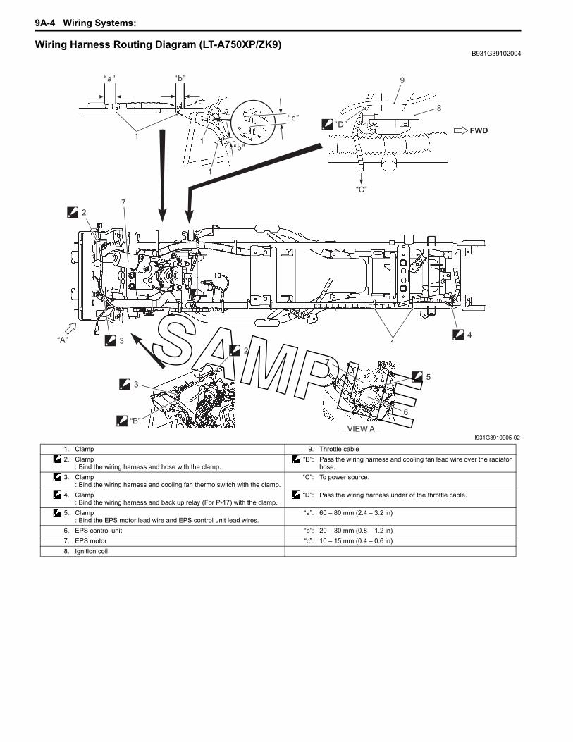
9A-4 Wiring Systems:
Wiring Harness Routing Diagram (LT-A750XP/ZK9)B931G39102004
“b”
2
3
3
“B”
21
4
7
6
5
VIEW A
“A”
1
“a” “b”
1
1
“c”“D”
8
9
“C”
7
FWD
I931G3910905-02
1. Clamp 9. Throttle cable2. Clamp
: Bind the wiring harness and hose with the clamp.“B”: Pass the wiring harness and cooling fan lead wire over the radiator
hose.3. Clamp
: Bind the wiring harness and cooling fan thermo switch with the clamp.“C”: To power source.
4. Clamp: Bind the wiring harness and back up relay (For P-17) with the clamp.
“D”: Pass the wiring harness under of the throttle cable.
5. Clamp: Bind the EPS motor lead wire and EPS control unit lead wires.
“a”: 60 – 80 mm (2.4 – 3.2 in)
6. EPS control unit “b”: 20 – 30 mm (0.8 – 1.2 in)7. EPS motor “c”: 10 – 15 mm (0.4 – 0.6 in)8. Ignition coil

Wiring Systems: 9A-5
“A”
1
(b)(a)
3
5
4
8
6
14
13
1617
15
7
9
12
“C”
18
10
“E”
“D”
2
11
11
“F”
VIEW F
VIEW A19
“B”
I931G3910903-02
1. Starter motor 14. Injector coupler2. Starter motor terminal 15. TP sensor coupler3. Engine earth 16. ISC valve coupler4. Clamp
: Bind the wiring harness and rear brake cable with the clamp.17. TO sensor
5. Clamp: Bind the wiring harness and diff-lock actuator lead wire with the clamp.
18. Horn (For P-17, 24)
6. Clamp: Bind the diff-lock actuator lead wire and rear brake switch lead wire with the clamp.
19. IAP sensor
7. Clamp: Bind the rear brake switch lead wire with the clamp.
“B”: To rear fender top.
8. Clamp: Bind the wiring harness, generator lead wire and gear position switch lead wire.
“C”: Slack the read wire.
9. Speed sensor lead wire. “D”: Pass the horn lead wire inside of the stay.10. Clamp “E”: Pass the branch of left headlight lead wire
over the radiator hose.11. Clamp : 10 N⋅m (1.0 kgf-m, 7.0 lbf-ft)12. Back up relay (For P-17) : 6 N⋅m (0.6 kgf-m, 4.5 lbf-ft)13. ECT sensor coupler

9A-6 Wiring Systems:
3
“a”
57 8
9
10
11
12
“A”VIEW
4
2
4
2
LH RH
“C”
1413
6
1
“A”
“D”
“B”
I931H1910903-05
1. Clamp: Bind the left handlebar switch lead wire, rear brake lever switch lead wire, horn lead wire (For P-17, 24) and emergency switch lead wire (For P-17) with the clamp. Cut the tip of clamp after clamping.
10. ECM
2. Clamp: Bind the combination meter lead wire, 2WD/4WD/diff-lock switch lead wire, ignition switch lead wire, front brake switch lead wire, parking/rear brake lever switch lead wire, left handlebar switch lead wire, horn lead wire (For P-17, 24) and emergency switch lead wire (For P-17) with the clamp. Cut the tip of clamp after clamping.
11. Fuse box
3. Clamp: Bind the front brake switch lead wire and 2WD/4WD/diff-lock switch lead wire with the clamp. Cut the tip of clamp after clamping.
12. Fuse (EPS)
4. Clamp: Bind the combination meter lead wire, 2WD/4WD/diff-lock lead wire and front brake switch lead wire with the clamp.
13. Combination meter lead wire
5. Horn button (For P-17, 24) 14. Ignition switch lead wire6. Emergency switch (For P-17) “a”: 10 – 15 mm (0.4 – 0.6 in)7. Drive relay “B”: Pass the combination meter lead wire behind the upper bracket.8. Starter relay “C”: Slack the combination meter lead wire under the combination
meter.9. Fuel pump relay “D”: Pass the front brake switch lead wire behind the handlebars.

Wiring Systems: 9A-7
SpecificationsTightening Torque Specifications
B931G3910S002NOTEThe specified tightening torque is described in the following.“Wiring Harness Routing Diagram (LT-A750XP/ZK9) (Page 9A-4)”
Reference:For the tightening torque of fastener not specified in this section, refer to “Tightening Torque List (LT-A750XP/ZK9) in Section 0C (Page 0C-7)”.
12
3
“a”
4
5
6
6
I931G3910904-01
1. Starter motor 3. Generator stator 5. Grommet “a”: 90°2. Gear position switch 4. Ground wire 6. Clamp

9E-1 Body Structure:
Body and AccessoriesBody StructureRepair Instructions
Body Frame Construction (LT-A750XP/ZK9)B931G39506011
Special Tools and EquipmentRecommended Service Material
B931G39508001NOTERequired service material is also described in the following.“Body Frame Construction (LT-A750XP/ZK9) (Page 9E-1)”
FWDFWD
3
2
4
4
1
I931G3950001-04
1. Frame 3. Washer : Apply thread lock to the thread part.2. Battery plate 4. Spacer

Prepared by
March, 2009
Part No. 99501-47050-01E
Printed in Japan
132

Printed in JapanK9


