346
| Date post: | 02-Mar-2016 |
| Category: |
Documents |
| Upload: | usernaga84 |
| View: | 2,216 times |
| Download: | 145 times |
7/18/2019 LTA Civil_standards- Civil Design Criteria
http://slidepdf.com/reader/full/lta-civilstandards-civil-design-criteria 1/345

7/18/2019 LTA Civil_standards- Civil Design Criteria
http://slidepdf.com/reader/full/lta-civilstandards-civil-design-criteria 2/345
All rights reserved. No part of this publication may be reproduced or transmitted in any form or by any means, electrical, mechanical,photocopying, recording or otherwise or stored in any retrieval systemof any nature, without prior written permission of the Land Transport Authority.
Published by Land Transport Authority

7/18/2019 LTA Civil_standards- Civil Design Criteria
http://slidepdf.com/reader/full/lta-civilstandards-civil-design-criteria 3/345
Revision History
Date Revision
Sept 1999 A1
Sept 2000 A2
Sept 2001 A3
Sept 2002 A4

7/18/2019 LTA Civil_standards- Civil Design Criteria
http://slidepdf.com/reader/full/lta-civilstandards-civil-design-criteria 4/345
DC/0/1
Sept 2002 Civil Design Criteria – Revision A4
C O N T E N T S
Chapter 1 GENERAL
Chapter 2 MRT ALIGNMENT AND STRUCTURE GAUGE
Chapter 3 LOADS
Chapter 4 TRACKWORK
Chapter 5 GEOTECHNICAL PARAMETERS
Chapter 6 FOUNDATIONS, EARTHWORKS AND PERMANENT RETAINING
STRUCTURES
Chapter 7 BORED TUNNELS AND RELATED WORKS
Chapter 8 UNDERGROUND STRUCTURES
Chapter 9 BRIDGES AND ABOVE-GROUND STRUCTURES
Chapter 10 ROADS
Chapter 11 STATION AND TUNNEL SERVICES FOR RAIL PROJECTS
Chapter 12 EXTERNAL WORKS
Chapter 13 E&M INTERFACE
Chapter 14 STRAY CURRENT CORROSION CONTROL FOR RAILWAYS
Chapter 15 NOT USED
Chapter 16 NOT USED
Chapter 17 NOT USED
Chapter 18 AUTOMATIC AND MANUAL IRRIGATION SYSTEM
Chapter 19 INSTRUMENTATION
Chapter 20 ASSESSMENT OF DAMAGE TO BUILDINGS AND UTILITIES
Chapter 21 LIGHTING SYSTEM

7/18/2019 LTA Civil_standards- Civil Design Criteria
http://slidepdf.com/reader/full/lta-civilstandards-civil-design-criteria 5/345
DC/0/2
Sept 2002 Civil Design Criteria – Revision A4
CHAPTER 1
GENERAL
1.1 INTRODUCTION1.1.1 Scope
1.1.2 Definitions1.1.3 General Obligations
1.2 STANDARDS1.2.1 Use of Singapore and British Standards1.2.2 Use of British Standard BS 54001.2.3 Use of United Kingdom Highways Agency Design Manual for
Roads and Bridges1.2.4 Partial Safety Factor for Strength of Reinforcement
1.3 DESIGN
1.3.1 Responsibility for Design1.3.2 Design Objectives1.3.3 Design of Temporary Works1.3.4 Design For Removal of Temporary Works1.3.5 Oversite and Adjacent Developments1.3.6 Governing Criteria
1.4 CALCULATIONS1.4.1 Method of Calculations1.4.2 Use of Computer Programs1.4.3 SI Units
1.4.4 Language
1.5 SURVEY & SETTING OUT1.5.1 Levels1.5.2 Co-ordinates
1.6 DURABILITY ASSURANCE1.6.1 Design Considerations1.6.2 Critical Elements1.6.3 Durability Assessment1.6.4 Life Cycle Cost Analysis
1.6.5 Drawings
1.7 MATERIALS AND WORKMANSHIP SPECIFICATION
1.8 DIMENSIONS
1.9 BLINDING
7/18/2019 LTA Civil_standards- Civil Design Criteria
http://slidepdf.com/reader/full/lta-civilstandards-civil-design-criteria 6/345
DC/0/3
Sept 2002 Civil Design Criteria – Revision A4
CHAPTER 2
MRT ALIGNMENT AND STRUCTURE GAUGE
2.1 INTRODUCTION
2.2 HORIZONTAL ALIGNMENT2.2.1 Definitions2.2.2 Horizontal Curves2.2.3 Cant and Speed2.2.4 Transition Curves2.2.5 Chainages2.2.6 Co-ordinates
2.3 VERTICAL ALIGNMENT2.3.1 Vertical Curves2.3.2 Gradients
2.3.3 Levels
2.4 TURNOUTS AND CROSSOVERS (for heavy and medium rail
systems only)2.4.1 Turnouts2.4.2 Closure Rails2.4.3 Diamond Crossings
2.5 STRUCTURE GAUGE AND CLEARANCES2.5.1 Definitions2.5.2 Train and Track Vehicles
2.5.3 Structure Gauge2.5.4 Throw2.5.5 Clearance to Structure Gauge2.5.6 Clearances at Platform Edge
7/18/2019 LTA Civil_standards- Civil Design Criteria
http://slidepdf.com/reader/full/lta-civilstandards-civil-design-criteria 7/345
DC/0/4
Sept 2002 Civil Design Criteria – Revision A4
CHAPTER 3
LOADS
3.1 GENERAL
3.2 LOADS FROM RAILWAY VEHICLES3.2.1 General3.2.2 Design for Protection of Structures against the Effects of Derailment
3.3 LOADS FROM ROAD VEHICLES3.3.1 General3.3.2 Loads on Underground Structures3.3.3 Load on Temporary Works including Temporary Decking
3.4 SURCHARGE LOADS
3.5 SOIL AND WATER LOADS3.5.1 Soil Unit Weights and Earth Pressure Coefficients3.5.2 Water
3.6 IMPOSED LOADS IN RAILWAY STATIONS3.6.1 Floor Loadings3.6.2 Escalators3.6.3 Lifts3.6.4 Cooling Tower/Water Tanks
3.7 WIND
3.7.1 Wind on Viaducts, Bridges, Gantries and other Road RelatedStructures
3.7.2 Wind on Stations and Other Structures3.7.3 Aerodynamic Effects3.7.4 Wind Load from Fans in Underground Railway Structures3.7.5 Wind Load from Trains in Below Ground Structures
3.8 PARAPETS AND HANDRAILING
3.9 LIFTING FACILITIES FOR EQUIPMENT3.9.1 Crane Gantry Girder
3.9.2 Overhead Runway Beams3.9.3 Eyebolts
3.10 PARTIAL SAFETY FACTORS FOR LOADS
3.11 SEISMIC LOADING

7/18/2019 LTA Civil_standards- Civil Design Criteria
http://slidepdf.com/reader/full/lta-civilstandards-civil-design-criteria 8/345
DC/0/5
Sept 2002 Civil Design Criteria – Revision A4
CHAPTER 4
TRACKWORK
4.1 INTRODUCTION
4.2 VEHICLE DATA
4.3 ELECTRICAL4.3.1 Power Return System4.3.2 Signalling System
4.4 TRACK SYSTEM4.4.2 Ballasted Track4.4.3 Slab Track4.4.4 Noise and Vibration attenuating track4.4.5 Level Crossing
4.4.6 Noise and Vibration4.4.7 Space Constraints4.4.8 Trackwork Components
4.5 TRACK INSULATION
4.6 MISCELLANEOUS4.6.1 Cable Troughs4.6.2 Buffer Stops4.6.3 Over-Voltage Protection Devices (OVPDs)4.6.4 Reference Points and Distance Indicators
4.6.5 Cross-Bonding and Jumper Cables4.6.6 Bonded Insulated Rail Joints4.6.7 Welding4.6.8 Trap Points
4.7 THIRD RAIL SYSTEM4.7.1 General4.7.2 Conductor Rail4.7.3 Joints in the Conductor Rail4.7.4 Ramps4.7.5 Conductor Rail Supports
4.7.6 Protective Cover
7/18/2019 LTA Civil_standards- Civil Design Criteria
http://slidepdf.com/reader/full/lta-civilstandards-civil-design-criteria 9/345
DC/0/6
Sept 2002 Civil Design Criteria – Revision A4
CHAPTER 5
GEOTECHNICAL PARAMETERS
5.1 GENERAL
5.2 HYDROGEOLOGY5.2.1 Rainfall5.2.2 Design Ground Water Levels
5.3 SOIL AND ROCK CLASSIFICATION
5.4 DESIGN PARAMETERS
5.5 SOIL AND GROUNDWATER CHEMISTRY
5.6 SITE INVESTIGATION
7/18/2019 LTA Civil_standards- Civil Design Criteria
http://slidepdf.com/reader/full/lta-civilstandards-civil-design-criteria 10/345
DC/0/7
Sept 2002 Civil Design Criteria – Revision A4
CHAPTER 6
FOUNDATIONS, EARTHWORKS
AND
PERMANENT RETAINING STRUCTURES
6.1 INTRODUCTION6.1.1 General6.1.2 Ground Movements6.1.3 Deleterious Substances in Soils6.1.4 Combining Foundation Types in a Single Structure
6.2 DESIGN REQUIREMENTS FOR FOUNDATIONS6.2.1 Shallow Foundations6.2.2 Deep Raft Foundations6.2.3 Deep Foundation Elements (DFEs)
6.3 SETTLEMENT/HEAVE6.3.1 General
6.4 DEBONDING OF PILES AND DEEP FOUNDATIONS
6.5 LOAD TESTING6.5.1 General6.5.2 Preliminary Load Tests6.5.3 Working Load Tests6.5.4 Quantity of Testing6.5.5 Selection of DFEs for testing
6.6 PERMANENT GRAVITY AND CANTILEVER RETAINING WALLS6.6.1 Lateral Earth Pressures6.6.2 Water Pressure6.6.3 Factors of Safety6.6.4 Use of DFEs for Retaining Structure Foundations6.6.5 Settlement and Deflections6.6.7 Seepage
6.7 EARTHWORKS6.7.1 General
6.7.2 Factor of Safety6.7.3 Embankment for Railway Tracks6.7.4 Soil Improvement6.7.5 Drainage6.7.6 Non-Suspended Apron Structures and Services
6.8 TRANSITION SLABS6.8.1 General6.8.2 Transition Slab for Roadways6.8.3 Transition Slab for Railways

7/18/2019 LTA Civil_standards- Civil Design Criteria
http://slidepdf.com/reader/full/lta-civilstandards-civil-design-criteria 11/345
DC/0/8
Sept 2002 Civil Design Criteria – Revision A4
6.9 USE OF FINITE ELEMENT OR FINITE DIFFERENCE
MODELLING TECHNIQUES6.9.1 Design Requirements6.9.2 Modelling Requirements6.9.3 Sensitivity Analysis6.9.4 Submission of Results
7/18/2019 LTA Civil_standards- Civil Design Criteria
http://slidepdf.com/reader/full/lta-civilstandards-civil-design-criteria 12/345
DC/0/9
Sept 2002 Civil Design Criteria – Revision A4
CHAPTER 7
BORED TUNNELS AND RELATED WORKS
7.1 GENERAL PRINCIPLES
7.2 TUNNEL SIZE
7.3 TUNNELS IN SOFT GROUND7.3.1 Definition of Soft Ground7.3.2 Design Method7.3.3 Flotation and Heave7.3.4 Longitudinal Stiffness
7.4 TUNNELS IN ROCK7.4.1 Definition of Rock7.4.2 Design Method
7.5 SEGMENTAL LINING DESIGN7.5.1 General7.5.2 Deflections7.5.3 Waterproofing7.5.4 Fixings7.5.5 Taper Rings7.5.6 Bolt Pockets
7.6 TEMPORARY TUNNEL LININGS7.6.1 Types of Lining
7.6.2 Sprayed Concrete Lining (SCL)7.6.3 Ribs and Lagging
7.7 IN-SITU TUNNEL LINING7.7.1 General7.7.2 Analysis7.7.3 Waterproofing7.7.4 Fixings
7.8 CROSS PASSAGEWAYS BETWEEN RAILWAY RUNNING
TUNNELS
7.8.1 Location7.8.2 Dimensions and Layout7.8.3 Design
7.9 SUMPS IN RUNNING TUNNELS
7.10 EMERGENCY ESCAPE SHAFTS7.10.1 Location7.10.2 Dimensions and Layout7.10.3 Shaft Design

7/18/2019 LTA Civil_standards- Civil Design Criteria
http://slidepdf.com/reader/full/lta-civilstandards-civil-design-criteria 13/345
DC/0/10
Sept 2002 Civil Design Criteria – Revision A4
7.11 TUNNEL WALKWAY IN RAILWAY TUNNELS7.11.1 Arrangement7.11.2 Details of Walkway
7.12 FIRST STAGE CONCRETE

7/18/2019 LTA Civil_standards- Civil Design Criteria
http://slidepdf.com/reader/full/lta-civilstandards-civil-design-criteria 14/345
DC/0/11
Sept 2002 Civil Design Criteria – Revision A4
CHAPTER 8
UNDERGROUND STRUCTURES
8.1 GENERAL8.1.1 Scope8.1.2 General Principles
8.1.3 General Requirements for Trainways in Cut-and-Cover Tunnelsand Stations
8.1.4 General Requirements for Vehicular Underpasses and DepressedCariageways
8.2 DESIGN APPROACH
8.3 ULTIMATE LIMIT STATE8.3.1 Structural Stability8.3.2 Robustness
8.4 SERVICEABILITY LIMIT STATE8.4.1 Settlement8.4.2 Cracking
8.5 DURABILITY8.5.1 Exposure Conditions8.5.2 Minimum Cover 8.5.3 Cement and Water Content8.5.4 Shrinkage and Thermal Cracking
8.6 FIRE RESISTANCE
8.7 INSPECTION OF CONSTRUCTION
8.8 LOADS8.8.1 Load Factors for Earth and Water Pressure8.8.2 Ground Loads8.8.3 Load Combinations8.8.4 Unbalanced Loads
8.9 ANALYSIS8.9.3 Locked-in Stress Resultants (moment, shear axial force, etc)
8.10 DETAILED DESIGN8.10.1 Redistribution of Moments (only applicable for structures designed
to SS CP 65)8.10.2 Design Moments8.10.3 Bottom Loaded Structural Elements8.10.4 Internal facing of Diaphragm and Secant Pile Walls8.10.5 Fixings for E&M Equipment8.10.6 Post Fixed Reinforcement8.10.7 Connections between Bored Tunnels / Cut-and-Cover Structures

7/18/2019 LTA Civil_standards- Civil Design Criteria
http://slidepdf.com/reader/full/lta-civilstandards-civil-design-criteria 15/345
DC/0/12
Sept 2002 Civil Design Criteria – Revision A4
8.10.8 Pile Foundations and Deep Foundation Elements8.10.9 Torsion (only applicable for structures designed to SS CP 65)
8.11 DETAILING8.11.1 Slabs and Walls8.11.2 Columns / Piers8.11.3 Beams (only applicable for structures designed to BS 5400)
8.11.4 Corner Details8.11.5 Construction Joints8.11.6 Slab to Wall Connections8.11.7 Detailing of Shear Links
8.12 CIVIL DEFENCE DESIGN (where applicable)
8.13 PROVISION FOR FUTURE DEVELOPMENT8.13.1 Knockout Panels for Access to Future Developments8.13.2 Fire Separation for Railway Structures8.13.3 Future Development Loads, Structural Capacity and Settlement /
Deflection8.13.4 Design Assumptions and Construction Constraints
8.14 FLOTATION8.14.1 General8.14.2 Factors and Safety8.14.3 Soil Friction8.14.4 Assessment8.14.5 Measures to Counteract Flotation
8.15 STABILITY OF THE EXCAVATION
8.16 WATERPROOFING
8.17 DESIGN OF TEMPORARY WORKS8.17.1 General Requirements8.17.2 Design of Temporary Excavation Support8.17.3 Design for Removal of Temporary Works8.17.4 Use of Finite Element or Finite Difference Modelling Techniques8.17.5 Minimum Unplanned Excavation8.17.6 Temporary Ground Anchorages
7/18/2019 LTA Civil_standards- Civil Design Criteria
http://slidepdf.com/reader/full/lta-civilstandards-civil-design-criteria 16/345
DC/0/13
Sept 2002 Civil Design Criteria – Revision A4
CHAPTER 9
BRIDGES AND ABOVE-GROUND STRUCTURES
9.1 GENERAL
9.2 STANDARDS AND CODES OF PRACTICE
9.3 ANALYSIS
9.4 LOADING9.4.1 Temperature loads9.4.2 Aerodynamic Effects
9.5 DESIGN CONSIDERATIONS AND REQUIREMENTS9.5.1 General9.5.2 Reinforced Concrete
9.5.3 Prestressed Concrete9.5.4 Reduction or Isolation of Vibration9.5.5 Design Surface Crack Width9.5.6 Member Shapes and Sizing9.5.7 Precast Segments9.5.8 Piled Foundation9.5.9 Piers9.5.10 Abutments9.5.11 Approach (Transition) Slab
9.6 BEARINGS
9.6.1 General9.6.2 Bearing Replacement
9.7 MOVEMENT JOINTS FOR DECKING SLABS9.7.1 Definitions9.7.2 General9.7.3 Movement Joints
9.8 WATERPROOFING AND MECHANICAL IRRIGATION SYSTEM
FOR FLOWER TROUGH IN ROAD VIADUCTS AND
PEDESTRIAN OVERHEAD BRIDGES
9.9 PARAPET SYSTEM ON VEHICULAR BRIDGES AND
PEDESTRIAN OVERHEAD BRIDGES9.9.1 General9.9.2 Additional Design Requirements on Vehicular Bridge Parapets
9.10 THERMAL RAIL FORCES
9.11 RAILWAY DECK FURNITURE, DRAINAGE AND
WATERPROOFING

7/18/2019 LTA Civil_standards- Civil Design Criteria
http://slidepdf.com/reader/full/lta-civilstandards-civil-design-criteria 17/345
DC/0/14
Sept 2002 Civil Design Criteria – Revision A4
9.12 ELECTRICAL AND MECHANICAL REQUIREMENTS

7/18/2019 LTA Civil_standards- Civil Design Criteria
http://slidepdf.com/reader/full/lta-civilstandards-civil-design-criteria 18/345
DC/0/15
Sept 2002 Civil Design Criteria – Revision A4
CHAPTER 10
ROADS
10.1 GENERAL
10.2 ROAD PAVEMENT
10.3 ROAD GEOMETRY10.3.1 Horizontal Alignment10.3.2 Horizontal Sight Distance10.3.3 Vertical Alignment10.3.4 Vertical Curves10.3.5 Compound Curves10.3.6 Reverse Curves and Broken-Back Curves10.3.7 Corner Radius10.3.8 Cross Slope
10.3.9 Transition Curves10.3.10 Superelevation10.3.11 Combined Vertical and Horizontal Alignment10.3.12 Lane Width10.3.13 Traffic Island10.3.14 Road Cross-Section Element10.3.15 Exits and Entries at Interchanges
10.4 VEHICULAR IMPACT GUARDRAIL
10.5 CLEARANCE TO STRUCTURE
10.6 KERBS
10.7 WALL OPENING/VEHICULAR BREAKDOWN LAY-
BY/EMERGENCY STAIRCASES
10.8 ROAD MARKING AND SIGNAGE10.8.1 Carriageway Markings10.8.2 Road Signs
10.9 INFORMATION SIGNS
10.9.1 Introduction10.9.2 Design Considerations10.9.3 Siting of Signs10.9.4 Materials for Sign10.9.5 Sign Support10.9.6 Blockage of Signs by trees10.9.7 Other Examples
10.10 SITING OF INFORMATION SIGNS

7/18/2019 LTA Civil_standards- Civil Design Criteria
http://slidepdf.com/reader/full/lta-civilstandards-civil-design-criteria 19/345
DC/0/16
Sept 2002 Civil Design Criteria – Revision A4
CHAPTER 11
STATION AND TUNNEL SERVICES FOR RAIL PROJECTS
11.1 GENERAL REQUIREMENTS11.1.1 Standard Codes and Regulations11.1.2 Approvals
11.1.3 Routing of Pipework and Services
11.2 DRAINAGE11.2.1 General11.2.2 Tunnel Drainage11.2.3 Station Drainage11.2.4 Station Pump Sumps11.2.5 Sump and Pump Design Directives11.2.6 Storm Water Drainage
11.3 SEWERAGE & SANITARY PLUMBING
11.3.1 General11.3.2 Design Code11.3.3 Design Directives11.3.4 Sewage Pump Sumps11.3.5 Sewage Ejector
11.4 WATER SERVICES11.4.1 General11.4.2 Water Supply System11.4.3 Water System for Fire Fighting11.4.4 Civil Defence (CD) Water System
11.5 ACCESS LADDERS11.5.1 General11.5.2 Design11.5.3 Material

7/18/2019 LTA Civil_standards- Civil Design Criteria
http://slidepdf.com/reader/full/lta-civilstandards-civil-design-criteria 20/345
DC/0/17
Sept 2002 Civil Design Criteria – Revision A4
CHAPTER 12
EXTERNAL WORKS
12.1 LAND BOUNDARIES
12.2 FLOOD PROTECTION
12.3 PAVED AREAS
12.4 IRRIGATION SYSTEMS AND LANDSCAPING
12.5 HANDRAILS AND RAILINGS
12.6 FENCING AND PROTECTION AGAINST UNAUTHORISED
ACCESS
7/18/2019 LTA Civil_standards- Civil Design Criteria
http://slidepdf.com/reader/full/lta-civilstandards-civil-design-criteria 21/345
DC/0/18
Sept 2002 Civil Design Criteria – Revision A4
CHAPTER 13
E&M INTERFACE
13.1 GENERAL
13.2 ELECTRICAL SUBSTATION13.2.1 Cable Chamber 13.2.2 Others
13.3 PLATFORM TOUCH VOLTAGE PROTECTION13.3.1 General13.3.2 Minimum Insulation Level13.3.3 Insulation Details
13.4 WATER AND ELECTRICAL EQUIPMENT13.4.1 General Protection
13.4.2 External Cable Manholes and Cable Ducts
13.5 E&M EQUIPMENT DELIVERY ROUTES
13.6 ELECTRICITY SUPPLY TO CIVIL EQUIPMENT
13.7 EARTHING SYSTEM13.7.1 General13.7.2 Earthing Mat Design Requirements13.7.3 Installation and Execution13.7.4 Testing
13.8 CABLE AND PIPE DUCTS
13.9 EQUIPOTENTIAL BONDING
13.10 CABLE BRACKETS AND OTHER E&M FIXINGS IN TUNNELS
7/18/2019 LTA Civil_standards- Civil Design Criteria
http://slidepdf.com/reader/full/lta-civilstandards-civil-design-criteria 22/345
DC/0/19
Sept 2002 Civil Design Criteria – Revision A4
CHAPTER 14
STRAY CURRENT CORROSION CONTROL FOR RAILWAYS
14.1 INTRODUCTION14.1.1 General
14.1.2 Design Considerations14.1.3 Operating Modes
14.2 SYSTEM REQUIREMENTS14.2.1 Trackwork14.2.2 Elevated MRT Stations and Viaducts (Fig. 14.1)14.2.3 Underground Structures (Fig. 14.2, Fig. 14.3, Fig. 14.4)14.2.4 At-Grade and Transition Sections (Fig. 14.5)14.2.5 Depots
14.3 SYSTEM COMPONENTS
14.3.1 Cabling14.3.2 Drainage Panels14.3.3 Drainage Terminal Boxes14.3.4 Reference Electrodes
14.4 STRAY CURRENT LEAKAGE PATH CONTROL14.4.1 General14.4.2 Installations14.4.3 Elevated Stations and Viaducts14.4.4 Underground Structures and Tunnels
14.5 SYSTEM TESTING AND MONITORING(refer to Fig. 14.6 to Fig. 14.9 and Appendix 2)
14.5.1 Track to Structure Earth and Water Earth Resistance14.5.2 Stray Voltage Level Monitoring14.5.3 Substation Drainage Current Measurements14.5.4 Other Tests14.5.5 Test Procedures

7/18/2019 LTA Civil_standards- Civil Design Criteria
http://slidepdf.com/reader/full/lta-civilstandards-civil-design-criteria 23/345
DC/0/20
Sept 2002 Civil Design Criteria – Revision A4
CHAPTER 18
AUTOMATIC AND MANUAL IRRIGATION SYSTEM
18.1 REGULATIONS, CODES AND STANDARDS
18.2 AUTOMATIC IRRIGATION SYSTEM DESCRIPTION
18.3 DESIGN CRITERIA
18.4 MICROPROCESSOR BASED IRRIGATION CONTROLLER
18.5 RAIN SHUT-DOWN
18.6 PUMPSETS18.6.1 Submersible Pumpset
18.7 SUMP PUMP
18.8 OPERATION OF PUMPS
18.9 SPRINKLER HEAD AND STREAM BUBBLER
18.10 PIPES AND FITTINGS
18.11 MANUAL IRRIGATION SYSTEM DESCRIPTION
18.12 DESIGN CRITERIA
18.13 PIPES AND FITTINGS
18.14 PIPE INSTALLATION
18.15 OTHER ACCESSORIES
7/18/2019 LTA Civil_standards- Civil Design Criteria
http://slidepdf.com/reader/full/lta-civilstandards-civil-design-criteria 24/345
DC/0/21
Sept 2002 Civil Design Criteria – Revision A4
CHAPTER 19
INSTRUMENTATION
19.1 INTRODUCTION
19.2 INSTRUMENTATION REQUIREMENTS
19.3 MONITORING PLANS AND RELATED DOCUMENTS19.3.1 Monitoring Drawings19.3.2 Instrumentation Tables19.3.3 Instrumentation Specifications
19.4 MINIMUM MONITORING19.4.1 Minimum Monitoring for Excavations19.4.2 Minimum Monitoring for Tunnels
19.4.4. Minimum Monitoring of Struts and Ground Anchors19.4.5. Minimum Monitoring of Buildings and Structures19.4.6. Minimum Monitoring of Utilities19.4.7. Minimum Monitoring for Areas of Ground Treatment19.4.8. Minimum Monitoring for Tunnelling Under Buildings19.4.9. Minimum Monitoring for Buildings Subject to Protective Measures19.4.10. Minimum Vibration Monitoring
19.5 ADDITIONAL MONITORING
19.6 READING FREQUENCY FOR MONITORING INSTRUMENTS
19.7 ACCURACY AND RANGE OF MONITORING INSTRUMENTS
19.8 REVIEW LEVELS

7/18/2019 LTA Civil_standards- Civil Design Criteria
http://slidepdf.com/reader/full/lta-civilstandards-civil-design-criteria 25/345
DC/0/22
Sept 2002 Civil Design Criteria – Revision A4
CHAPTER 20
ASSESSMENT OF DAMAGE TO BUILDINGS AND UTILITIES
20.1 GENERAL
20.2 PREDICTION OF SETTLEMENTS20.2.1 Ground Movements due to Bored Tunnelling20.2.2 Ground Movements due to Excavations20.2.3 Combined effects
20.3 ASSESSMENT OF DAMAGE TO BUILDINGS
20.4 ASSESSMENT OF DAMAGE TO UTILITIES
20.5 PROTECTIVE WORKS

7/18/2019 LTA Civil_standards- Civil Design Criteria
http://slidepdf.com/reader/full/lta-civilstandards-civil-design-criteria 26/345
DC/0/23
Sept 2002 Civil Design Criteria – Revision A4
CHAPTER 21
LIGHTING SYSTEM
21.1 PUBLIC STREET LIGHTING21.1.1 General
21.1.2 Luminaires Requirements21.1.3 Works in Conjunction with Lighting
21.2 VEHICULAR UNDERPASS LIGHTING21.2.1 General21.2.2 Emergency Lighting21.2.3 Luminaires Requirements
21.3 TUNNEL LIGHTING21.3.1 General21.3.2 Design Parameters
21.3.3 Glare Control21.3.4 Emergency Lighting

7/18/2019 LTA Civil_standards- Civil Design Criteria
http://slidepdf.com/reader/full/lta-civilstandards-civil-design-criteria 27/345
DC/1/1
Sept 2002 Civil Design Criteria – Revision A4
CHAPTER 1
GENERAL
1.1 INTRODUCTION
1.1.1 Scope
The Design Criteria give the requirements for the design and detailing of all Civil Engineering Works for the Land Transport Authority.
Unless stated otherwise, the requirements of the Design Criteria are for Permanent Works.
1.1.2 Definitions
The definitions of “Authority“, “Contractor“ and “Works“ etc. shall be those
given in the Conditions of Contract.
The term Engineer used in the Design Criteria refers to the Engineer appointed by the Authority for the purposes of the Contract. Where theConditions of Contract require instead that a Superintending Officer beappointed for the purposes of the Contract, the term Engineer in thisSpecification shall refer to the Superintending Officer so appointed by the
Authority.
The use of the terms “railways”, “stations” etc, shall be taken to apply toall guided systems, whether MRT or LRT, whether steel on steel or rubber
tyres on guideways etc, unless specifically stated otherwise or agreedotherwise with the Engineer.
The definition of “nominal cover” shall be the design depth of concretecover to all steel reinforcement, including links. It shall be the dimensionused in design and indicated on the design drawings.
1.1.3 General Obligations
1.1.3.1.1 Compliance with Statutory Requirements and International Standards
All designs shall be carried out and fully endorsed by ProfessionalEngineers holding a valid practising certificate and registered under theProfessional Engineers Act, Singapore in the civil and/or structuraldiscipline and registered Accredited Checkers in accordance with theBuilding Control Act.
All designs shall comply with all Building and Safety Regulations includingthe Building Control Act.
Compliance with a Singapore Standard (SS) or British Standard (BS) or astandard approved by the Authority (or accepted by the Engineer) or the
7/18/2019 LTA Civil_standards- Civil Design Criteria
http://slidepdf.com/reader/full/lta-civilstandards-civil-design-criteria 28/345
DC/1/2
Sept 2002 Civil Design Criteria – Revision A4
requirements of these Design Criteria shall not confer immunity from legalobligations.
1.1.3.2 Adjacent Works
The design shall take into account any constraints or effects imposed bythe existing and planned works and services in the surrounding areas,
and works of other nearby contractors.
1.2 STANDARDS
1.2.1 Use of Singapore and British Standards
The design of all Works shall comply with the appropriate currentstandards and/or Codes of Practice issued by the Productivity andStandards Board (PSB), or if such a standard and/or Code of Practicedoes not exist, then the appropriate current standard issued by the British
Standards Institution (BSI). If an appropriate standard from PSB and BSIdoes not exist and no other standard is stated in the Contract Documents,then subject to the acceptance of the Engineer and the Commissioner of Building Control of The Building and Construction Authority, anappropriate current standard from a reputable institution may be used.Three English language copies of such proposed standards shall besubmitted to the Engineer.
Generally the requirements spelt out in the Particular Specification,General Specification, M&W Specification and the Design Criteria shalltake precedence over any relevant Singapore or British Standards, UK
Highways Agency Standards and advisory notes or other InternationalCodes of Practices.
Where metric unit and imperial unit version of the same standard exist,the metric version shall apply.
1.2.2 Use of British Standard BS 5400
1.2.2.1 Unless noted otherwise use of BS 5400 shall be as implemented by theUnited Kingdom Highways Agency Standards and Advisory notes and asfurther amended by the Design Criteria.
1.2.2.2 References made within the Design Criteria to BS 5400 Part 2 shall be tothe composite version of BS 5400 Part 2 (which forms an appendix to theUnited Kingdom Highways Agency Departmental Standard BD 37/88)and as further amended by the Design Criteria.

7/18/2019 LTA Civil_standards- Civil Design Criteria
http://slidepdf.com/reader/full/lta-civilstandards-civil-design-criteria 29/345
DC/1/3
Sept 2002 Civil Design Criteria – Revision A4
1.2.3 Use of United Kingdom Highways Agency Design Manual for Roads
and Bridges
The design shall also comply with the following Standards contained inthe Design Manual for Roads and Bridges, except where explicitly statedotherwise in the Design Criteria:
BD 15/92 General Principles for the Design & Construction of Bridges – Use of BS 5400: Pt 1 1988
BD 16/82 Design of Composite Bridges – Use of BS 5400Pt 5: 1979
BD 20/92 Bridges Bearings – Use of BS 5400 Pt 9: 1983BD 24/92 Design of Concrete Highway Bridges and Structures
– Use of BS 5400 Pt 4: 1990BD 27/86 Materials for the Repair of Concrete Highway
StructuresBD 28/87 Early Thermal Cracking of Concrete
BD 30/87 Backfilled Retaining Walls and Bridges AbutmentsBD 32/88 Piled FoundationsBD 33/94 Expansion Joints for Use in Highway Bridge DecksBD 36/92 The Evaluation of Maintenance Costs in Comparing
Alternative Designs for Highway StructuresBD 37/88 Loads for Highway BridgesBD 52/93 The Design of Highway Bridge ParapetsBD 60/94 Design of Highway Bridges for Collision LoadsBA 26/94 Expansion Joints for Use in Highway Bridge DetailsBD 49/93 Design Rules for Aerodynamic Effects on Bridges
1.2.4 Partial Safety Factor for Strength of Reinforcement
The partial safety factor for strength of reinforcement shall be taken as1.15 (and not 1.05 as given in BS 8110 table 2.2).
1.3 DESIGN
1.3.1 Responsibility for Design
Staff with proven relevant experience shall be deployed to design and
detail the Works using their skills to the best of their abilities to achievethe design objectives described in Clause 1.3.2 below.
1.3.2 Design Objectives
The design of structures and civil engineering works shall meet thefollowing objectives: they shall be safe, robust, economical, durable, withoperation and maintenance costs reduced to a practicable minimum, andshall be fit for purpose. Simplicity of structural form and layout is tobe preferred. All structures shall be designed to be aestheticallypleasing.
7/18/2019 LTA Civil_standards- Civil Design Criteria
http://slidepdf.com/reader/full/lta-civilstandards-civil-design-criteria 30/345
DC/1/4
Sept 2002 Civil Design Criteria – Revision A4
The elements of all structures shall be designed and detailed to achievethe design objectives by, inter alia, the following:
(a) appropriate selection of materials(b) consideration of the long term deterioration of materials in the
service environment
(c) due care in design and detailing so as to facilitate goodworkmanship in construction and the achievement of design intent
(d) consideration of access and other requirements for inspection andmaintenance
(e) adoption of good engineering practice(f) use of low risk construction methods and proven techniques
The durability objective of the project shall be to achieve a service life,with appropriate maintenance, of 120 years for all structures. Themeasure of achievement of durability shall be that all the criteria set in thedesign shall be maintained throughout the service life. Deterioration of
materials shall be taken into account in the design and specification of theworks.
Due diligence and skills shall be applied in the design and detailing toensure that the works can be constructed economically, practically andsafely.
All structural designs shall comply with all the ultimate and serviceabilitylimit states.
1.3.3 Design of Temporary Works
All Temporary Works shall be designed and detailed to be compatiblewith the Permanent Works.
Temporary Works designs shall be carried out and endorsed by aProfessional Engineer.
Any part of the Permanent Works that performs a temporary functionduring construction shall be defined as Permanent Works and shall beanalysed for both conditions (permanent and temporary) and designedusing Permanent Works design criteria for the more onerous condition.
The exception to this is crack width requirements for embedded walls, for which the appropriate clause should be consulted.
1.3.4 Design For Removal of Temporary Works
1.3.4.1 All Temporary Works outside the limits of the following shall bedesigned for removal:
(a) For road projects, the smaller of the road reserve and an areabounded by a line 3m from the footprint of the Permanent Works
7/18/2019 LTA Civil_standards- Civil Design Criteria
http://slidepdf.com/reader/full/lta-civilstandards-civil-design-criteria 31/345
DC/1/5
Sept 2002 Civil Design Criteria – Revision A4
(b) For railway projects, the smaller of the Railway Area (as definedin the Rapid Transit Systems Act) and an area bounded by a line3m from the footprint of the Permanent Works
1.3.4.2 Within the limits stated in the above clause, Temporary Works shallalso be designed to be removed. Exceptionally, within these limits theContractor may propose to leave Temporary Works in place, where it is
impracticable to remove them.
Prior to installation the Contractor shall gain the acceptance of theEngineer for any such proposal.
1.3.4.3 Temporary Works shall be designed such that there is no risk of damage to the Permanent Works during removal.
Unless otherwise accepted by the Engineer, all voids left in the grounddue to the extraction of temporary works shall be backfilled with grout.The grout mix and method of backfilling shall be submitted to the
Engineer for acceptance.
1.3.4.4 Where it is agreed that Temporary Works may be left in the ground theyshall be designed so that there will be no risk of ground settlement or other deleterious effects as a consequence of decay of timber or other materials.
In all cases Temporary Works shall be designed to be removed to adepth of 2 metres below the finished ground level unless shownotherwise on the Authority’s Drawings. This shall also apply to allsecant and diaphragm walls and the like.
Details of the construction sequence assumed, identification of theTemporary Works that are not to be removed (if any) and provisionsmade in the design to satisfy the above requirements shall be detailedon the Temporary Works design drawings.
Any Temporary Works not removed shall be shown on the as-builtdrawings.
1.3.5 Oversite and Adjacent Developments
All structures are to be designed wholly independently of any benefitwhich might be obtained from oversite or adjacent development. For example, in consideration of stability against flotation or of any lateralloading, the design should allow for the development not being presentif that gives a more onerous design case.
1.3.6 Governing Criteria
Unless specifically stated otherwise in the Particular Specification, wherethere are different criteria for design stated in the Contract Documents,
7/18/2019 LTA Civil_standards- Civil Design Criteria
http://slidepdf.com/reader/full/lta-civilstandards-civil-design-criteria 32/345
DC/1/6
Sept 2002 Civil Design Criteria – Revision A4
Standards and Codes of Practice or relevant statutory regulations, themost onerous shall apply.
1.4 CALCULATIONS
1.4.1 Method of Calculations
Unless otherwise varied by the subsequent Chapters of the DesignCriteria, all calculations shall be carried out in accordance with therequirements and recommendations of appropriate current Standards.
The use of "State-of-the-Art" methods of calculations or methods thathave not been extensively tried and proven within the industry will not bepermitted unless prior acceptance for their use has been obtained fromthe Engineer. The design shall be in accordance with established goodengineering practice and principles.
1.4.2 Use of Computer Programs
The use of computers is permitted, provided the computer programs to beused are accepted by the Engineer.
The programs to be used shall be those that are produced by reputablesoftware houses and have undergone extensive testing. In this respect,the relevant documents and sample calculations to demonstrate theaccuracy and reliability of the programs shall be submitted. Details of computer programs, including assumptions, limitations and the like, shallbe clearly explained in the design statement.
All input and output data of a computer program shall be clearly definedand the calculations shall include clear and unambiguous information of what each parameter means in the computer output forms.
When in-house spreadsheets are used, the proposed version of thespreadsheet shall be clearly indicated and submitted together withhand calculations to verify the results of the spreadsheet for all possiblecalculation scenarios. A print-out of the spreadsheet showing theformulas normally hidden shall also be submitted with the cellreferences clearly labelled along the top and left hand margins of each
page.
1.4.3 SI Units
All calculations shall be carried out and presented in SI Units as specifiedin BS 3763. The units of stress shall be N/mm2 or kN/m2.
1.4.4 Language
All calculations and other documents shall be submitted in the EnglishLanguage.

7/18/2019 LTA Civil_standards- Civil Design Criteria
http://slidepdf.com/reader/full/lta-civilstandards-civil-design-criteria 33/345
DC/1/7
Sept 2002 Civil Design Criteria – Revision A4
1.5 SURVEY & SETTING OUT
1.5.1 Levels
All levels given on the design drawings shall refer to a Project datum100m below Singapore Standard Datum.
1.5.2 Co-ordinates
All co-ordinates given on the design drawings shall be based on theproject co-ordinate system as defined in the Particular Specification. Theproject co-ordinate system shall be clearly defined and indicated on thedesign drawings.
1.6 DURABILITY ASSURANCE
1.6.1 Design Considerations
The design shall address the durability of all elements of the structures.The design process shall incorporate an assessment of potentialdeterioration of materials in their exposure environments (e.g. exposure toground water) throughout the service life, including but not limited to:
(a) durability of concrete,(b) corrosion of metals,(c) long term performance of sealants, waterproofing, coatings and
other forms of protection,(d) serviceability of embedded pipework, services etc.
(e) maintenance/replacement of architectural finishes.
Construction processes which are critical to the achievement of durabilityshall be identified. These include workability requirements for castingconcrete around relatively congested reinforcement sections, and durationof placement in terms of delay in setting to avoid cold joints.
1.6.2 Critical Elements
Particular attention shall be given to deterioration of elements whichcannot practically be accessed for maintenance or repair during the
service life. In the case of such critical elements, the design shall bepremised on the element (including all its components) remaining durablethroughout the service life without maintenance. Additional measuresshall be incorporated in the design of such elements to address theeventuality of the primary protection failing to achieve the desireddurability. Where normal methods of inspection are impossible, provisionfor monitoring material performance by instrumentation shall beimplemented where practicable.
7/18/2019 LTA Civil_standards- Civil Design Criteria
http://slidepdf.com/reader/full/lta-civilstandards-civil-design-criteria 34/345
DC/1/8
Sept 2002 Civil Design Criteria – Revision A4
1.6.3 Durability Assessment
Based on the durability objectives of the project, performance criteria for materials shall be developed from an assessment of the following:
(a) the micro-environment to which the element is exposed(b) potential deterioration mechanisms in this micro-environment
(c) the likely material life(d) the feasibility and cost of in situ monitoring, maintenance and/or repair
(e) the necessity and cost-effectiveness of providing additionalprotection
(f) the significance of deterioration.
In addition to the assessment of “the likely material life”, the qualitycontrol tests to monitor the quality of concrete for durability and theacceptance criteria shall also be provided.
Any proposal to revise the Materials and Workmanship specificationsshall be based on the performance criteria arising from suchconsiderations.
1.6.4 Life Cycle Cost Analysis
Where required by the following chapters, life cycle cost analysis shallbe undertaken as a basis for selection of materials. Such analysis willrequire prediction of material performance and life of all components of the element (jointing and waterproofing materials, fixings etc.) andcompare the total life costs of viable options, by summation of:
(a) initial capital cost, including any monitoring system that is to beinstalled during the construction phase,
(b) recurrent costs of inspection, maintenance/repair,(c) replacement (where feasible)
Total life costs, shall be expressed in present day dollars by usingdiscounted cash flow techniques based on 5% discount rate. Theanalysis is to be used as a decision making process and coststherefore need only be sufficiently accurate for the purposes of comparison of options. A sensitivity analysis shall be undertaken toreflect the uncertainties related to:
(a) predictions of material performance(b) workmanship in construction(c) unit rates for calculation of inspection, maintenance, repair and
replacement costs.
1.6.5 Drawings
The design characteristic strength, the maximum nominal aggregatesize, the minimum cement content, maximum cement content, and

7/18/2019 LTA Civil_standards- Civil Design Criteria
http://slidepdf.com/reader/full/lta-civilstandards-civil-design-criteria 35/345
DC/1/9
Sept 2002 Civil Design Criteria – Revision A4
maximum free water: cement ratio and permitted cement types shall beshown clearly on the design drawings for reinforced, precast andprestressed concrete works together with any other restrictions onmaterials or properties required.
1.7 MATERIALS AND WORKMANSHIP SPECIFICATION
Attention is drawn to the obligation to review the Materials andWorkmanship Specification. Attention shall be drawn to any provisionof the Materials and Workmanship Specification which appearsincompatible with the design basis, and appropriate modifications to theMaterials and Workmanship Specification shall be proposed, andagreed with the Engineer. The Materials and WorkmanshipSpecification should however be regarded as a minimum standard.
1.8 DIMENSIONS
All dimensions given on the Authority’s Drawings or within the Authority’s documentation shall be taken to be minimum dimensions tobe achieved on site after allowance for all construction tolerances,deflection of embedded walls, sagging of beams and floors, etc.
1.9 BLINDING
Reinforced and/or prestressed concrete shall be cast against anadequate concrete blinding and not directly against the ground. The
minimum concrete grade and thickness shall be C20 and 75mmrespectively. The thickness and strength of blinding may need to beincreased depending on the softness and irregularity of the ground andthe thickness of the concrete pour. Where the ground beneath theblinding is to be removed at a later date (for example in top-downconstruction) a debonding membrane shall be used at the interfacebetween the blinding and reinforced concrete. The blinding andmembrane details shall be indicated on the design drawings.

7/18/2019 LTA Civil_standards- Civil Design Criteria
http://slidepdf.com/reader/full/lta-civilstandards-civil-design-criteria 36/345
DC/2/1
Sept 2002 Civil Design Criteria – Revision A4
CHAPTER 2
MRT ALIGNMENT AND STRUCTURE GAUGE
2.1 INTRODUCTION
The final alignment of the railway shall conform to the Design Criteriaand shall take full account of the following:-
• Operating requirements
• Signalling requirements
• Traction power requirements
• Rolling stock requirements
• Minimise traction power
• Minimise track maintenance
• Construction constraints and cost
• Minimise conflict with existing structures and utilities
• Geotechnical and tunnelling conditions
• Environmental conditions
• Land use considerations
The design shall be co-ordinated with all relevant designers,contractors and other authorities
2.2 HORIZONTAL ALIGNMENT
2.2.1 Definitions
2.2.1.1 Track gauge is the distance measured between the inside face of thetwo running rails at a point 14.1mm below the crown of the rails(gauge points). For heavy and medium rail systems track gauge shallbe 1435mm.
2.2.1.2 Horizontal alignment – non-tunnel is the alignment based on a pointmidway between gauge points.
2.2.1.3 Horizontal alignment – in tunnel is the alignment based on a point onthe track centre line at a height above the rail line co-incident with thecentre of the train mass. (For definitions of rail line and track centre linesee Clause 2.5.1.2)
2.2.1.4 Circular Curve is a curve of constant radius.
2.2.1.5 Compound Curve is a curve formed of two or more circular curves of differing radii curving in the same direction. The circular curves may or may not be linked by transition curves.

7/18/2019 LTA Civil_standards- Civil Design Criteria
http://slidepdf.com/reader/full/lta-civilstandards-civil-design-criteria 37/345
DC/2/2
Sept 2002 Civil Design Criteria – Revision A4
2.2.1.6 Reverse Curve is a curve formed of two or more circular curves curvingin alternate directions which may or may not be of the same radius andwhich may or may not be linked by transition curves. A reverse curvehas no straight track between each circular curve but has abuttingtransition curves. For the purpose of the alignment, each part of areverse curve shall be given a separate curve number.
2.2.1.7 Transition Curve is a curve of progressively varying radius used to linkeither a straight with a circular curve, or two circular curves of differentradii.
2.2.1.8 Virtual Transition is a length over which a train car experiences achange from straight to circular curve when no transition curve occurs.Its length is equal to the spacing between the car’s bogies and istheoretically placed symmetrically about the tangent point.
2.2.1.9 Cant (Superelevation) is the vertical distance (in millimetres) by whichone rail is raised above the other and measured between the crowns of
the two running rails. Cant is positive when the outer rail on a curve israised above the inner rail or negative when the inner rail is raisedabove the outer.
2.2.1.10 Equilibrium Cant is the cant required to enable a vehicle to negotiate acurve at a particular speed, known as the equilibrium speed, such thatthe resultant of the weight of the train and its centrifugal force isperpendicular to the plane of the rails.
2.2.1.11 Applied Cant in millimetres is the actual cant specified for the curve.
2.2.1.12 Cant Deficiency in millimetres is the amount by which the applied cantis less than the equilibrium cant for the speed being considered.
2.2.1.13 Excess Cant is the amount by which the applied cant is greater thanthe equilibrium cant for the speed being considered.
2.2.1.14 Cant Gradient expressed as a dimensionless ratio, is the gradient atwhich applied cant or cant deficiency is increased or reduced.
2.2.1.15 Rate of Change of Cant or of Cant Deficiency in millimetres per secondis the rate at which cant or cant deficiency is increased or reduced
relative to the speed of the vehicle.
2.2.1.16 Line Speed Limit (in km/h) is the maximum speed permitted for anytrain anywhere on the line.
2.2.1.17 Restricted Speed is the nominal maximum permissible speed for asection of track imposed by means of a permanent speed restrictionand is determined by the comfort and safety condition criteria.
2.2.1.18 Design Speed at a particular point on the track is the average speed of the train at that point under average running conditions calculated from

7/18/2019 LTA Civil_standards- Civil Design Criteria
http://slidepdf.com/reader/full/lta-civilstandards-civil-design-criteria 38/345
DC/2/3
Sept 2002 Civil Design Criteria – Revision A4
the coasting run speed profiles prepared by the signalling or rollingstock designer.
2.2.1.19 Flatout speed at a particular point on the track is the average speed of the train at that point using maximum accelerating and brakingcapacities on a run between two adjacent stations and is calculatedfrom the flatout speed profiles prepared by the signalling or rolling
stock designer.
2.2.1.20 Shift is the amount by which the centre of radius of a circular curveneeds to move due to the placement of transition curves.
2.2.2 Horizontal Curves
2.2.2.1 The limits for radii for horizontal circular curves are shown below.
Mainline Depot,Temporary &
non - passenger Tracks
AbsoluteMinimum
PreferredMinimum
AbsoluteMinimum
Heavy Railsystem
400m 500m 190m
Medium Railsystem
300m 400m 190m
For light rail systems refer to the manufacturer’s recommendations.
2.2.2.2 The track shall preferably be straight throughout the length of stations.The presence of external constraints may necessitate limitedencroachment of curves at station ends.
2.2.2.3 Track through platforms shall be straight. Transitions shall normally bepositioned so as to avoid horizontal throw (see Clause 2.5.1.4)affecting platform nosing clearance. Where encroachment isunavoidable, this shall be limited such that the combined effects of vehicle throw and cant do not affect the location of the nosing atplatform ends by more than 20 mm when compared to straight track.
2.2.2.4 Circular curve radii shall be selected to be the maximum practicable.The radius selected for any particular curve shall not be so large as tounnecessarily impose more severe curvature of the track at either endof that curve.

7/18/2019 LTA Civil_standards- Civil Design Criteria
http://slidepdf.com/reader/full/lta-civilstandards-civil-design-criteria 39/345
DC/2/4
Sept 2002 Civil Design Criteria – Revision A4
2.2.2.5 The combination of circular curve and their related transition curvesshall be chosen such that the length of pure circular arc betweentransitions is not less than the following: -
Preferred minimum 50 metresDesirable minimum 25 metres
Absolute minimum 17 metres
2.2.2.6 For any two consecutive circular curves with the same direction of curvature, the length of straight track between the ends of the curves or of the transitions where these are required shall not be less than thefollowing: -
Preferred minimum 50 metresDesirable minimum 25 metres
Absolute minimum 17 metres
2.2.2.7 For any two consecutive circular curves with opposite direction of
curvature other than reverse curves, the length of straight trackbetween the ends of the curves or of the transitions where these arerequired shall not be less than the values given in Clause 2.2.2.6above.
2.2.3 Cant and Speed
2.2.3.1 The curve-speed-cant relationship shall be based on the followingequations :-
11.82 Ve²Equilibrium cant E = -------------
R_________
Maximum permissible speed Vm = 0.29 √ R (Ea + D)
where R = horizontal curve radius in metres
Vm = maximum permissible speed in kilometres per hour
Ve = equilibrium speed in kilometres per hour
E = equilibrium cant in millimetres
Ea = actual applied cant in millimetres
D = maximum allowable deficiency of cant in millimetres
Formulae are only applicable for a track gauge of 1435mm.

7/18/2019 LTA Civil_standards- Civil Design Criteria
http://slidepdf.com/reader/full/lta-civilstandards-civil-design-criteria 40/345
DC/2/5
Sept 2002 Civil Design Criteria – Revision A4
2.2.3.2 The maximum allowable applied cant shall be:
Absolute Maximum Desirable Maximum
For concrete track 150mm 125mmFor ballasted track 125mm 110mm
2.2.3.3 The amount of cant deficiency or excess cant at any point on the lineshall be limited to the following :-
Plain Line
Desirable Maximum 90mm for comfort conditions
Absolute Maximum 100mm for comfort conditions
Maximum deficiency for trains not carrying passengers 230mm for safety conditions
Turnouts
Maximum 90mm for comfort conditions
Maximum deficiency for trains not carrying passengers 125mm for safety conditions
2.2.3.4 Cant shall be selected to suit the design speed (typically 70% of equilibrium cant). Cant deficiency shall be checked against flatoutspeed to suit comfort condition criteria and cant shall be adjusted
upwards as necessary. Consideration for both cant and cant deficiencyshall also take into account the requirements of Clauses 2.2.4.3. and2.2.4.4
2.2.3.5 Where constraints on the alignment design are such that therequirements of Clause 2.2.3.4 cannot be met, a permanent speedrestriction shall be imposed. Such restrictions shall be minimised as far as practicable.
2.2.3.6 Permanent speed restrictions shall also be imposed as necessary toprevent a train at line speed limit breaching the safety condition criteria.
2.2.3.7 Suitable cant values shall be estimated during the preliminary design.The cant shall be finally selected from a consideration of the designspeed and flatout speed.
2.2.3.8 Applied cant shall be specified to the nearest millimetre for concretetrack and to the nearest 5 mm for ballasted track.

7/18/2019 LTA Civil_standards- Civil Design Criteria
http://slidepdf.com/reader/full/lta-civilstandards-civil-design-criteria 41/345
DC/2/6
Sept 2002 Civil Design Criteria – Revision A4
2.2.4 Transition Curves
2.2.4.1 In general for all mainline track, transition curves shall be providedwherever possible between a circular curve and adjoining straighttrack, between the different radii of a compound curves and at theadjoining ends of circular curves forming reverse curves.
2.2.4.2 Transition curves shall be clothoids.
2.2.4.3 The cant gradient (not cant deficiency) shall be subject to the followinglimits:-
Absolute maximum = 1 : 500Preferred = 1 : 750Minimum = 1 : 1000
2.2.4.4 The rate of change of cant or cant deficiency shall be limited asfollows:-
Plain Line
Desirable maximum = 35mm/sec for comfort conditions.
Absolute maximum = 55mm/sec for comfort conditions.
Maximum for trains = 125mm/sec for safety conditions.not carrying passengers.
Turnouts
Absolute maximum = 80mm/sec for comfort conditions.
Maximum for trains = 125mm/sec for safety conditions.not carrying passengers.
2.2.4.5. In cases where the design speed of the train on part or all of a curve isconsiderably less than the line speed limit, it may be necessary toimpose a permanent speed restriction to ensure that any excess cantat the design speed is kept to a practical minimum.
2.2.4.6 Transition curves will not normally be required between the differentradii of a compound curve where the change of radius of curvaturedoes not exceed 15% of the smaller radius. Change in cant is appliedover an effective transition length centred on the point where radiichange and of a length to satisfy the requirement of Clause 2.2.4.4 or car bogie centres whichever is greater .
2.2.4.7 Where a compound circular curve is employed with a change of radiusgreater than 15% of the smaller radius, a transition curve shall beinterposed between the two parts of the curve. The length of such a
7/18/2019 LTA Civil_standards- Civil Design Criteria
http://slidepdf.com/reader/full/lta-civilstandards-civil-design-criteria 42/345
DC/2/7
Sept 2002 Civil Design Criteria – Revision A4
transition shall be equal to the difference between the requiredtransition lengths at each end of the curve.
2.2.4.8 When the shift of any calculated transition curve would be less than 10mm, the actual transition curve may be omitted. In this case, therequired change of cant shall be applied over a length to satisfy therequirement of Clause 2.2.4.4 or car bogie centres whichever is the
greater, and in the same location as if the transition had been provided.
2.2.4.9 The length of transition curves shall wherever possible be based on thepreferred cant gradient in accordance with Clause 2.2.4.3 above. Incases where it is necessary to exceed the preferred cant gradient, therate of change of cant shall be limited in accordance with Clause2.2.4.4 above.
2.2.4.10 Transitions between reverse curves shall wherever practicable havethe same cant gradient for both transitions.
2.2.5 Chainages
2.2.5.1 The datum of chainages for new lines will be provided by the Authority.
2.2.5.2 Chainages shall be quoted in metres correct to four decimal places andshall be measured along the centre line of each individual track in planwith no correction for differences in elevation.
2.2.5.3 Initially a nominal 10m jump in chainage shall be provided on eachtrack at each station centre line. Subsequent alignment revisions that
results in changes to chainages shall be reflected by revising the jumps. The chainage at Contract boundaries shall not be changed.
2.2.6 Co-ordinates
2.2.6.1 Calculations for the setting out of the horizontal alignment for eachtrack shall be based on co-ordinates of horizontal intersection points of the nominal track centre line.
2.2.6.2 Co-ordinates shall be quoted in metres correct to four places of
decimals. Horizontal curve radii shall be quoted in metres correct tothree places of decimals and shall be the actual required radii after shifthas been taken into account. Deflection angles shall be quoted indegrees to the nearest one-tenth of a second.

7/18/2019 LTA Civil_standards- Civil Design Criteria
http://slidepdf.com/reader/full/lta-civilstandards-civil-design-criteria 43/345
DC/2/8
Sept 2002 Civil Design Criteria – Revision A4
2.3 VERTICAL ALIGNMENT
2.3.1 Vertical Curves
2.3.1.1 Ideally vertical curves shall be positioned such that coincidence withhorizontal curves and, in particular with horizontal transitions isavoided. Where such coincidence is necessary, the maximum
desirable practicable vertical curve radius shall be employed except atstation ends where a hump profile is used where a radius of 1600mshall be selected.
2.3.1.2 Vertical curves shall for each location be selected on the basis of themost suitable radius of the following: -
3000 m radius (maximum desirable radius)2500 m radius (preferred radius)2000 m radius1600 m radius (minimum allowable radius)
2.3.1.3 The length of the constant grade between consecutive vertical curvesshall be as follows: -
Desirable minimum 50 m Absolute minimum 25 m
2.3.1.4 At switches and crossings, vertical curves shall not coincide with anypart of the overall length of switches or crossings. In other areas of turnouts, vertical curves shall be avoided whenever possible. Wherethey cannot be avoided, the vertical curve radius shall be the maximum
in accordance with Clause 2.3.1.2 above.
2.3.1.5 At station ends where vertical curves are provided in conjunction withacceleration/deceleration gradients, the tangent point of the verticalcurve may be permitted only under severe constraints of the alignmentto encroach within the length of the platform to a limited extent. Thislength of encroachment shall be such that the vertical offset of thecurve from the station gradient at the platform end shall not exceed 15mm.
2.3.2 Gradients
2.3.2.1 The maximum gradients are shown below.
Down-hill Gradient Up-hill Gradient
Heavy Rail system 3% 2.5%
Medium Rail system 3% 3%
7/18/2019 LTA Civil_standards- Civil Design Criteria
http://slidepdf.com/reader/full/lta-civilstandards-civil-design-criteria 44/345
DC/2/9
Sept 2002 Civil Design Criteria – Revision A4
For light rail systems maximum gradients shall be in accordance withthe manufacturer’s recommendations.
2.3.2.2 At stations, the track shall be level throughout the platform lengthexcept for the limited lengths of vertical curves as specified in Clause2.3.1.5 above.
2.3.2.3 A drainage gradient shall be provided for all underground tracks, other than at platforms and sidings, as follows: -
Desirable minimum 0.5% Absolute minimum 0.25% (to be used in exceptionalcircumstances only)
2.3.2.4 On ballasted track, level tracks may be employed provided drainage iscatered for below the ballast.
2.3.2.5 Siding tracks should either slope 0.25% towards the buffers, or be
level.
2.3.2.6 Where practicable within the bored sections of tunnels,acceleration/deceleration gradients shall be provided in the form of ahump profile between stations. The nominal value of the hump shall be8 m but no more than 10m. Where tunnels are constructed by cut-and-cover methods, hump profiles need not be employed.
2.3.3 Levels
2.3.3.1 All levels shall be quoted in metres correct to four decimal places and
referred to Project Datum.
2.3.3.2 Rail level on superelevated ballasted track refers to the level at thecrown of the lower rail.
2.3.3.3 Rail level on superelevated concrete slab track refers to the mid pointbetween the two running rails and is unaffected by the application of cant.
2.4 TURNOUTS AND CROSSOVERS (for heavy and medium rail
systems only)
2.4.1 Turnouts
2.4.1.1 Turnouts shall comply with recognised international design practicesand geometries.
2.4.1.2 Turnouts shall not coincide with transition curves. Turnouts should beavoided where possible on horizontal curves.
2.4.1.3 A minimum speed limit of 55 km/h shall be allowed for through turnoutswhere regular passenger trains would normally operate.

7/18/2019 LTA Civil_standards- Civil Design Criteria
http://slidepdf.com/reader/full/lta-civilstandards-civil-design-criteria 45/345
DC/2/10
Sept 2002 Civil Design Criteria – Revision A4
2.4.1.4 Drawings should state co-ordinates of the intersection point of turnoutsand the chainage of beginning (BC point) and end of turnout.
2.4.1.5 The minimum radii of curves within turnouts shall be 190m.
2.4.2 Closure Rails
Distance between adjacent turnouts shall be designed to consider factors such as electrical problems (third rail gapping), signalling futuremaintenance issues and track stability. As a guide, the minimumlength of closure rails between adjacent turnouts on the same track areas follows: -
Turnouts switch toe to switch toe(BC to BC)
Turnout following another turnout(End of turnout to BC of next
turnout)
Desirableminimum
Absoluteminimum
Desirableminimum
Absoluteminimum
21m* 4.9m 9.1m 4.9m
* Applicable only to third rail systems
Note: BC = Geometrical tangent point (Beginning of curve)
End of turnout is defined as the location where the minimum dimension(shown below) between the gauge points of the diverging crossing legsis achieved.
1:7.5 - 190m Radius 500mm
1:9 - 190m Radius 420mm
1:9 - 300m Radius 420mm
1:12 - 500m Radius 380mm
1:14 - 500m Radius 350mm
2.4.3 Diamond Crossings
2.4.3.1 Diamond crossings shall be avoided unless deemed necessary.
7/18/2019 LTA Civil_standards- Civil Design Criteria
http://slidepdf.com/reader/full/lta-civilstandards-civil-design-criteria 46/345
DC/2/11
Sept 2002 Civil Design Criteria – Revision A4
2.5 STRUCTURE GAUGE AND CLEARANCES
2.5.1 Definitions
2.5.1.1 The normal co-ordinated axes of a vehicle are defined as thoseorthogonal axes, normal to the longitudinal centre line of the vehicle,where one axis called the wheel line is the line connecting the points of
bearing of pairs of wheels on the rails and the second, perpendicular tothe first, called the vehicle centre line, is central between the wheels.
2.5.1.2 The normal co-ordinated axes of the track are defined as thoseorthogonal axes, normal to the longitudinal centre line of the track,where one axis, called the rail line is the common tangent to the tops of the rails and the second perpendicular to the first, called the track centre line, is central between the rails.
2.5.1.3 The static load gauge is defined as the profile related to the theoreticalnormal co-ordinated axes of the passenger vehicle outside which no
part of the vehicle shall protrude when the vehicle is stationary andunloaded and when all play in the axles and suspension are uniformlydistributed either side. Building tolerances for the vehicle are includedin the static load gauge.
2.5.1.4 Horizontal throw is the distance measured parallel to the rail line of thevehicle centre line from the track centre line when a vehicle is on ahorizontal curved track, and all play in the axles and suspension areuniformly distributed either side.
Horizontal throw reaches (arithmetic) maximum midway betweenbogies and at the ends of the vehicle. These throws are called centrethrow and end throw respectively.
2.5.1.5 Vertical throw is defined in a similar manner when a vehicle is onvertically curved track.
2.5.1.6 The Kinematic Load Gauge is defined as the vehicle profile related tothe designed normal co-ordinated axes of the vehicle which covers themaximum possible distances from the vehicle centre line to any part of the vehicle taking into account the most unfavourable positions for
running, including tolerances and wear
2.5.1.7 The Kinematic Envelope is defined as the profile related to thedesigned normal co-ordinated axes of the track which covers themaximum possible distances from the track of any part of the vehicletaking into account the most unfavourable positions for running,including tolerances and wear of the track. When enlarged horizontallyand vertically on curved track to allow for throw, it is referred to as theSwept Envelope.

7/18/2019 LTA Civil_standards- Civil Design Criteria
http://slidepdf.com/reader/full/lta-civilstandards-civil-design-criteria 47/345
DC/2/12
Sept 2002 Civil Design Criteria – Revision A4
2.5.1.8 The Structure Gauge is defined as the profile related to the designednormal co-ordinated axes of the track into which no part of anystructure or fixed equipment may penetrate, taking into account alldeformations and movements.
2.5.1.9 The Service Vehicle Load Gauge is the Kinematic Load Gauge for those rail vehicles used for construction and maintenance
2.5.1.10 The Construction Gauge is the structure gauge, which shall applyduring construction until the time that trial running commences.
2.5.2 Train and Track Vehicles
2.5.2.1 All rail vehicles used for construction and maintenance will conform tothe service vehicle load and shall not influence the design of the civilworks.
2.5.3 Structure Gauge
2.5.3.1 The Structure Gauge shall be based upon the Kinematic Envelope insuch a way that each point on the perimeter of the Kinematic Envelopeis enlarged vertically upwards by 50mm and horizontally by 100mm(two points to be constructed for each point on the KinematicEnvelope). The Structure Gauge is the largest envelope based on thepoints constructed as described above. Below the vehicle, theKinematic Envelope is enlarged by 15mm to form the lower limit of theStructure Gauge. The shortest distance between the KinematicEnvelope and the Structure Gauge at any point is the Clearance at thatpoint.
2.5.3.2 Special provisions will be made to permit the intrusion of the platformnosing, the platform screen doors and platform edge columns into theStructure Gauge.
2.5.3.3 The Structure Gauge for curved track shall in all cases include anallowance for the maximum vehicle throw, both horizontal and verticalat the location being considered in accordance with Clause 2.5.4.1.
2.5.4 Throw
2.5.4.1 Horizontal throw can take the form of either centre throw or end throw.They are inversely proportional to the curve radius. When a vehicle isfully on a circular curve throw may be calculated from the formulae.
Centre throw (mm) = B2
103
8R
End throw (mm) = (T2-B2 )103
8R

7/18/2019 LTA Civil_standards- Civil Design Criteria
http://slidepdf.com/reader/full/lta-civilstandards-civil-design-criteria 48/345
DC/2/13
Sept 2002 Civil Design Criteria – Revision A4
B= Distance between bogie centres (metres)R= Radius in metresT= Overall length of vehicle (metres)
2.5.4.2 On circular curves, throw may be calculated in accordance with Clause2.5.4.1 above. On transitions and on straight track adjacent totransitions, throw shall be calculated based on the vehicle
characteristics. A “swept envelope” method may be employed.
2.5.4.3 An allowance shall be made for horizontal throw throughout the lengthof points and crossing and on the straight track adjacent to theseareas. Similarly a “swept envelope” method may be employed.
2.5.5 Clearance to Structure Gauge
2.5.5.1 All structure and equipment shall be designed to be clear of theStructure Gauge with adequate allowance made to take into account alltolerances of construction and fixing, and for all deflections and
displacements.
2.5.5.2 All moveable equipment, hinged doors, windows, etc close to the trackshall be positioned so that they are not within the Structure Gauge atevery position of movement. All covers to sumps, pits, etc within thetrack slab shall not infringe the Structure Gauge when in the openposition.
2.5.5.3 Where two tracks are side-by-side with each track capable, within theconstraints of the signalling system, of passing trains at the same time,the minimum clearance between the two tracks shall be such that the
Structure Gauges do not overlap.
2.5.6 Clearances at Platform Edge
2.5.6.1 Alongside the station platform limited intrusion into the Structure Gaugeof the platform edge, platform edge columns and screen doors ispermitted; see Structure Gauge Drawing.
2.5.6.2 The platform edge shall be set such that 75mm clearance is providedhorizontally between the static load gauge and the platform edge.Where a curved and/or canted track is less than 20 m from the
platform, the platform edge distance shall be increased to account for effect of cant and throw. The distance shall be calculated precisely, for the worst position of the train.
2.5.6.3 The screen doors shall be set at a distance of 115mm (+10 - 0 mm)from the static load gauge.
2.5.6.4 Intrusions into the Structure Gauge permitted in Clause 2.5.6.1 shallextend no further than the section of the station platform within thelength of a train stopped in the centre of the platform.

7/18/2019 LTA Civil_standards- Civil Design Criteria
http://slidepdf.com/reader/full/lta-civilstandards-civil-design-criteria 49/345
DC/2/14
Sept 2002 Civil Design Criteria – Revision A4
2.5.6.5 Passageway and staircases beyond the platform and end barriers near ends of platform shall be designed to be clear of Structure Gauge.
2.5.6.6 Alongside depot platforms, intrusions into the Structure Gauge are alsopermitted. The platform edge shall be set at 115mm (+20 - 0 mm) fromthe static load gauge where the curved track is at least 20 m beyondthe platform.
7/18/2019 LTA Civil_standards- Civil Design Criteria
http://slidepdf.com/reader/full/lta-civilstandards-civil-design-criteria 50/345
DC/3/1
Sept 2002 Civil Design Criteria – Revision A4
CHAPTER 3
LOADS
3.1 GENERAL
Loads shall be determined from The Building Control Regulations 4thSchedule, BD 37/88 (see Design Criteria clause 1.2.2) and BS 6399except where stated otherwise in this Chapter. In any circumstanceswhere there is a discrepancy between the relevant standards andregulations the more onerous shall apply.
The following loads and effects shall be considered in the design of allstructures:
(a) Dead Load(b) Superimposed dead load
(c) Load from adjacent building foundations or other structures(d) Surcharge load(e) Live load (primary and secondary) or imposed load(f) Earth Pressure(g) Hydrostatic Pressure(h) Temperature effects(i) Effects of shrinkage and creep in concrete(j) Erection forces and effects(k) Differential settlement(l) Wind Load(m) Collision Load
(n) Any other forces and effects arising out of the special nature of anystructure
This Chapter specifies the general loading requirements. For loadingrequirements specific to the type of structure being designed referenceshall be made to the relevant Chapter.
The loads given in these Design Criteria shall be treated as unfactored(nominal or characteristic) loads for design purposes unless specificallynoted otherwise (Therefore partial safety factors shall be applied inaccordance with the limit state methods of the relevant standard, for
example BS 5400, SS CP 65, etc.).
All unfactored (nominal or characteristic) live loads, imposed loads andsuperimposed dead loads shall be shown clearly on a comprehensive setof loading plans.
7/18/2019 LTA Civil_standards- Civil Design Criteria
http://slidepdf.com/reader/full/lta-civilstandards-civil-design-criteria 51/345
DC/3/2
Sept 2002 Civil Design Criteria – Revision A4
3.2 LOADS FROM RAILWAY VEHICLES
3.2.1 General
3.2.1.1 MRT
Notwithstanding the particular rolling stock to be used, the design live
loading from MRT railway vehicles shall be not less than that asdetermined in accordance with BS 5400 Part 2 for RL loading, or suchother loading as specified in the Particular Specification. Dynamic effectsshall be allowed for in accordance with BS 5400 Part 2 unless indicatedotherwise in the Particular Specification.
3.2.1.2 LRT
The design live loading from LRT vehicles, unless indicated otherwise inthe Particular Specification, shall be not less than the larger of the actualsystem requirement or one half of RL loading determined in accordance
with BS 5400 Part 2. Dynamic effects shall be allowed for in accordancewith BS 5400 Part 2 unless indicated otherwise in the Particular Specification.
3.2.2 Design for Protection of Structures against the Effects of
Derailment
3.2.2.1 General Considerations
The following design requirements apply to the supporting structuresfor new bridges or new buildings and any new structure carrying
hazardous materials (e.g. gas) constructed over or alongside railwaytracks. They do not apply to lineside railway infrastructure such asoverhead line masts or signal gantries.
Wherever possible, supports carrying any structure over or alongsiderailway tracks should be placed outside the “danger zone” (see belowfor definition).
Where supports must be placed inside the danger zone they shouldpreferably be monolithic piers rather than individual columns.
Columns and piers located within embankments, or at the bottom of embankments, may require special consideration even if outside thedanger zone because of the possibility of derailed vehicles rolling downthe embankment (See Figure 3.2.2.1-A below). If it is not possible toarrange the design to avoid the situation then special measures will benecessary to safeguard such columns and piers. Consideration shallbe given to the following:
(a) the use of guard rails(b) a retaining structure to widen the embankment(c) the use of massive piers.
7/18/2019 LTA Civil_standards- Civil Design Criteria
http://slidepdf.com/reader/full/lta-civilstandards-civil-design-criteria 52/345
DC/3/3
Sept 2002 Civil Design Criteria – Revision A4
Figure 3.2.2.1-A
Where isolated columns are used within the danger zone a solid‘deflector’ plinth shall be provided to a minimum height of 900mmabove the rail level or 1200mm above ground level whichever is thehigher. The height of the plinth shall be constant and the ends of theplinth shall be suitably shaped in plan to deflect derailed vehicles awayfrom the columns (See Figure 3.2.2.1-B below for typical plinth detail).For individual columns within station areas a solid platform construction
shall be used to provide similar protection from derailed vehicles.
Track
Danger Zone
5250mm5250mm
Embankment
Bottom of Embankment
Columns LocatedOutside Danger Zone

7/18/2019 LTA Civil_standards- Civil Design Criteria
http://slidepdf.com/reader/full/lta-civilstandards-civil-design-criteria 53/345
DC/3/4
Sept 2002 Civil Design Criteria – Revision A4
Figure 3.2.2.1-B

7/18/2019 LTA Civil_standards- Civil Design Criteria
http://slidepdf.com/reader/full/lta-civilstandards-civil-design-criteria 54/345
DC/3/5
Sept 2002 Civil Design Criteria – Revision A4
Where, exceptionally, the use of ground anchors are accepted as partof the Permanent Works by the Engineer and where they are situatedwithin the danger zone, special measures shall be taken to protect theanchorages from potential damage by derailed vehicles.
3.2.2.2 Definition of “danger zone”
Within tunnels the danger zone is considered to be bounded by thetunnel walls. At stations, it is bounded on the platform side(s) by theplatform structure below platform slab level, and above platform slablevel by a zone up to 2500mm from track centre-line; at non-platformlocations it is bounded by the nearest continuous wall or 5250mm fromtrack centre-line whichever is less. See Figure 3.2.2.2-A below.
Figure 3.2.2.2-A “danger zone” within stations
5250mm ( If there is nocontinuous wall within 5250mmfrom track centreline
Platform Structure
Platform Slab Level
2500mm
N e a r e s
t C o n t i n u o u s W a l l ( w h e r e a p p l i c a b
l e )
T r a c k C e n t r e l i n e
“danger zone”Platform Side
“danger zone”Non-PlatformSide
7/18/2019 LTA Civil_standards- Civil Design Criteria
http://slidepdf.com/reader/full/lta-civilstandards-civil-design-criteria 55/345

7/18/2019 LTA Civil_standards- Civil Design Criteria
http://slidepdf.com/reader/full/lta-civilstandards-civil-design-criteria 56/345
DC/3/7
Sept 2002 Civil Design Criteria – Revision A4
The above impact loads shall be considered in combination withpermanent loads together with appropriate live loads (where inclusionof live load is more critical) as defined below:
(a) Structures Designed to SS CP 65 or BS 5950
Irrespective of the number of storeys, structures designed to SS CP65 or BS 5950 shall be checked in accordance with therequirements of those codes for the effects of exceptional loads or localised damage (refer SS CP 65 Clauses 2.4.3.2 and 2.4.4.2, or BS 5950 Clause 2.4.5.4 etc)
(b) Structures Designed to BS 5400
Structures designed to BS 5400 shall be checked for this purposein accordance with United Kingdom Highways AgencyDepartmental Standard BD 60/94 using the ultimate loads
(equivalent to the partial load factor (γfL) multiplied by the nominalimpact load) given in Appendix 1 of this Chapter. γf3 shall beapplied in accordance with the code requirements.
3.2.2.4 Disproportionate Collapse
For all buildings irrespective of the number of storeys, all loadbearingelements, whose nearest face defines the boundary of, or lies withinthe danger zone, shall be detailed in accordance with SS CP 65 Clause2.2.2.2 including the provision of vertical ties, or BS 5950 Clause2.4.5.3, as appropriate. For the purposes of this clause each level of a
station shall count as one storey.
Structures whose nearest face defines the boundary of, or lies within,the danger zone shall be designed as follows:
(a) Where individual columns are used within the danger zone, thedesign of the structure above them shall incorporate such continuitythat the removal of any one column will not lead to the collapse of more than a limited portion of the structure close to the element inquestion under permanent loads, together with the appropriate liveloads.
(b) Where however the load bearing element is required to act as akey element defined for the purposes of this clause as one whoseremoval would cause the collapse of more than a limited portion of the structure close to the element in question, the following shallapply:
(i) Tunnels and underground stations
The key element shall be designed for a horizontal ultimatedesign load of P3 at a height of H3 above adjacent

7/18/2019 LTA Civil_standards- Civil Design Criteria
http://slidepdf.com/reader/full/lta-civilstandards-civil-design-criteria 57/345
DC/5/10
Sept 2002
Table 5/4 - Summary of Soil and Groundwater Propert
SOIL
MATERIAL pH Total Sulphates(% SO3) SO3 in 1:1 Extract(g/l)
SO3 in 2:1 Extract(g/l)
pH
stuarine Clay (E) 39 7.7 2.2 79 22 2.8 0.01 9 20 7.95 0.01 4 1 2.8 2.8 0 9 8.0 4.9
arine Clay (M) 57 8.8 3.4 7 48 1.59 0.4 4 8 4.3 0.02 0 8 3.9 0.26 38 15 11 6.8
luvial Sand (F1) 5 7.4 5.1 0 - - - - 4 0.08 0.02 0 1 2.3 2.3 0 6 7.7 6.0
luvial Clay (F2) 9 7.7 4.3 55 4 0.23 0.02 0 2 0.09 0.02 0 3 1.2 0.8 0 1 6.7 6.7
urong Formation
S/S3)
23 8.4 3.2 13 19 0.76 0 0 4 6.8 0.01 25 - - - - 34 8.5 4.3
ukit Timahormation (G)
42 8.9 3.9 17 1.9 0.16 0 0 18 0.15 0.01 0 3 2.79 0.2 0 24 5.1 4.0
N u m b e r o f
S a m p l e s
M a x . V a l u e
M i n . V a l u e
% i n C l a s s
4 o r 5
N u m b e r o f
S a m p l e s
M a x . V a l u e
M i n . V a l u e
% i n C l a s s
4 o r 5
N u m b e r o f
S a m p l e s
M a x . V a l u e
M i n . V a l u e
% i n C l a s s
4 o r 5
N u m b e r o f
S a m p l e s
M a x . V a l u e
M i n . V a l u e
% i n C l a s s
4 o r 5
N u m b e r o f
S a m p l e s
M a x . V a l u e
M i n . V a l u e
ote 1: Due to sampling difficulties during the initial investigation groundwater samples are indicative only groundwater in the region of the borehole and these have been assigned to the predominant ground
ote 2: Classification system makes no allowance for any concentration factors.
ote 3: High Chloride concentrations and low resistivity of groundwaters were associated with local areas.
ote 4: Low pH values may have been influenced by aerobic bacterial activity.

7/18/2019 LTA Civil_standards- Civil Design Criteria
http://slidepdf.com/reader/full/lta-civilstandards-civil-design-criteria 58/345
DC/3/8
Sept 2002 Civil Design Criteria – Revision A4
trackbed level (or ground level as appropriate). For designs
to BS 5400, γf3 shall be applied in accordance with the coderequirements.
Within tunnels and underground stations, the point load can
act in a direction parallel to or up to D1 degrees from thedirection of the adjacent track. At crossovers within
tunnels, the direction of the load within 1 metre of the endsof dividing walls is parallel to or up to D2 degrees from thedirection of the adjacent main-line track.
Refer to Appendix 1 of this Chapter for values of P3 andH3.
The structures shall be checked for these loads in thesame way as for loads P1 and P2 in clause 3.2.2.3 above.
(ii) Depot
Alongside test track: (iii) below applies.
Elsewhere at the Depot: provided train speeds are low(typically less than 20 kph) in the Depot, the design toclause 3.2.2.3 above constitutes a design as a keyelement. Otherwise (iii) below applies.
(iii) Other Areas (e.g. Viaducts and At-Grade Structures)
The key element shall be designed for a horizontal ultimate
design load of P3 at a height of H3 above adjacenttrackbed level (or ground level as appropriate). For designs
to BS 5400, γf3 shall be applied in accordance with the coderequirements.
Within the Depot and outside of the tunnels, the point loadcan act in any direction, and the design shall cater for themost adverse direction(s).
Refer to Appendix 1 of this Chapter for values of P3 andH3.
The structures shall be checked for these loads in the
same way as for loads P1 and P2 in clause 3.2.2.3 above.
3.3 LOADS FROM ROAD VEHICLES
3.3.1 General
Vehicular live loads shall comply with BD 37/88 except where modifiedbelow:
7/18/2019 LTA Civil_standards- Civil Design Criteria
http://slidepdf.com/reader/full/lta-civilstandards-civil-design-criteria 59/345
DC/3/9
Sept 2002 Civil Design Criteria – Revision A4
3.3.1.1 Carriageway (replaces BD 37/88 Clause 3.2.9.1)
The definition of carriageway in Clause 3.2.9.1 of BD 37/88 shall bereplaced by the following:
‘For the purposes of this standard, that part of the running surfacewhich includes all traffic lanes, hard shoulders, hard strips and
marker strips. The carriageway width is the width betweenparapets. The carriageway width shall be measured in a directionat right angle to the line of parapets, lane marks or edge marking.’
3.3.1.2 Vehicular Live Loads (modifies BD 37/88 Clause 6)
Vehicular live loads shall comply with the requirements of Clause 6 of BD37/88, subject to the following modifications:
(a) For HA Uniformly Distributed Load (UDL) a factor of 1.2 shall beapplied to the uniformly distributed load specified in BD 37/88
Clause 6.2.1 as given below:
(i) For loaded lengths from 2 metres up to and including 50metres
W = 1.2x336 (1/L)0.67
(ii) For loaded lengths in excess of 50 metres but less than500 metres.
W = 1.2x36 (1/L)0.1
Where L is the loaded length in metres and W is the load per metre of notional lane in kN.
Table 13 of BD 37/88 is accordingly superseded by theabove.
(iii) For loaded lengths above 500 metres, the UDL shall beagreed with the Engineer.
(iv) HA lane factors: Type HA UDL and Knife Edge Load shall
be multiplied by the appropriate lane factors as follows:
For application of type HA UDL and KEL, at least two lanesshall have a lane factor of 1.0 and the other lanes shall havelane factors of 0.6. Table 14 in BD 37/88 is accordinglysuperseded by the above.
(b) HA Wheel Load
In addition to the single wheel load of 100 kN specified in BD 37/88Clause 6.2.5, a separate load case of 2 nos. of 120 kN wheel loads

7/18/2019 LTA Civil_standards- Civil Design Criteria
http://slidepdf.com/reader/full/lta-civilstandards-civil-design-criteria 60/345
DC/3/10
Sept 2002 Civil Design Criteria – Revision A4
placed transversely, 2m apart, shall also be considered in the designfor local effects.
(c) HA Longitudinal Traction or Braking force
The nominal HA longitudinal traction and braking force shall be 10kN/m applied to an area one notional lane wide multiplied by the loaded
length plus 200 kN, subject to a maximum of 800 kN.
(d) HB Loading
All structures shall be designed for 45 units of HB loading (180 T).However, the HB loading shall be restricted to the centre 5m strip of the carriageway with all other lanes closed to traffic except for thefollowing cases:
(i) 45 units of HB is free to travel anywhere between theparapets along the slip roads or loops of the interchange
or flyover with no other associated loadings on thestructure.
(ii) 45 units of HB is free to travel anywhere between theparapets for 80 metres of the main structure prior to theapproach to the slip road or loop with no other associatedloading on the structure.
All structures shall also be designed for 30 units of HB loading (120T)in co-existence with the relevant HA loadings. The application of loading shall be in accordance with BD 37/88 Clause 6.4.2.
Where two separate carriageways are supported on one structure, onlyone number of 45 units of HB loading needs to be considered at anyone time. Type HA loading shall be applied to the other carriageway if the resultant load case is more onerous.
(e) Collision Loads(i) Road and railway bridge and viaduct structures:
The minimum height clearance of any structure above allroads shall be 5.4 metres. However, any structure having
a clear height less than 5.7 metres shall be designed for collision loads on superstructures in accordance with therequirements of the United Kingdom Highways AgencyDepartmental Standard BD 60/94.
Substructural elements, such as columns, situated withinthe Road Reserve or less than 4.5m from the edge of thecarriageway shall be designed to withstand vehiclecollision loads as specified in BD 60/94. The collisionload shall be considered even if there is provision of single or double vehicular impact guard rails to these

7/18/2019 LTA Civil_standards- Civil Design Criteria
http://slidepdf.com/reader/full/lta-civilstandards-civil-design-criteria 61/345
DC/3/11
Sept 2002 Civil Design Criteria – Revision A4
elements or even when there is no vehicular access tocolumn positions.
(ii) Pedestrians Overhead Bridges:
The minimum height clearance of any structure above allroads shall be 5.4 metres. However, any structure having
a clear height less than 5.7 metres shall be designed for collision loads on superstructures as follows:
• For bridge spans over expressways or semi-expressways, collision loads shall be in accordancewith BD 60/94.
• For bridge spans over roadways other thanexpressways or semi-expressways, collision loadsshall be in accordance with BD 37/88 Clause 6.8.
Where Pedestrian Overhead Bridge piers are located lessthan 4.5m from the edge of expressway or semi-expressway carriageways, they shall be designed for collision loads on supports in accordance with BD 60/94.
Where Pedestrian Overhead Bridge piers are located lessthan 4.5m from the edge of other roadway carriageways,they shall be designed for collision loads on supports inaccordance with BD 37/88 Clause 6.8. BD 37/88 Clause7.2 shall not be used.
The collision loads on bridge support structures shall beconsidered even if double vehicular impact guardrails areprovided to these elements.
3.3.1.3 Pedestrian Bridge Loads
(a) Pedestrian Live Load (Modifies BD 37/88 Clause 7.1.1)The nominal pedestrian live load shall be 5kN/m2 unless otherwisestated.
(b) Live load for roof structures
Minimum provision of nominal live load of 0.5kN/m2
shall beprovided for roof structures or future installation of roof structuresover pedestrian bridges.
(c) Dead load for roof structuresMinimum provision of nominal dead load of 1.0kN/m2 shall beprovided for roof structure or future installation of roof structuresover pedestrian bridges.
7/18/2019 LTA Civil_standards- Civil Design Criteria
http://slidepdf.com/reader/full/lta-civilstandards-civil-design-criteria 62/345
DC/3/12
Sept 2002 Civil Design Criteria – Revision A4
3.3.2 Loads on Underground Structures
3.3.2.1 Under roadways, structures shall be designed to resist the followingvehicular live loads:
(a) Vehicular live load and partial surcharge as derived from the -following as appropriate:
(i) For depths of cover less than or equal to 600mm above topof structural roof slab level, full vehicular live loads asspecified in Clause 3.3.1 above in conjunction with auniformly distributed load of 5kN/m2.
(ii) For depths of cover above top of structural roof slab inexcess of 600mm, the more critical of:
• HA wheel load and HB loading (as specified in Clause3.3.1 above and modified in Clauses 3.3.2.3 and 3.3.2.4below) in conjunction with a uniformly distributed load of
5kN/m2
.• HB loading (as specified in Clause 3.3.1 above and
modified in Clauses 3.3.2.3 and 3.3.2.4 below) inconjunction with a uniformly distributed load of 5kN/m2.
• HA wheel load in conjunction with a uniformly distributedload of 5kN/m2.
(b) Surcharge load as specified in Clause 3.4. No other loads fromroad vehicles need to be applied with this surcharge.
These loads shall be placed anywhere above, straddling or to the side of
the structure to the extent that will give the most onerous load effect for the element of structure under consideration.
3.3.2.2 In the case of Underground Structures serving road vehicles (e.g.Vehicular underpass), vehicular live loads inside and on top of thevehicular underpass shall be assumed to co-exist with the exception thatonly one type HB loading will be considered for any given loadingcombination.
3.3.2.3 Application of the HB vehicles shall be as follows:
Only 45 units of type HB loading shall be considered for design of Underground Structures. The 45 units of type HB loading shall be placedanywhere inside or on top of the vehicular underpass with co-existing HAloading on that carriageway, where more onerous. HA loading shall beapplied on all the other carriageways simultaneously, where moreonerous.
3.3.2.4 Dispersal of loads:(a) The HA Knife Edge Load may be dispersed through the surfacing
7/18/2019 LTA Civil_standards- Civil Design Criteria
http://slidepdf.com/reader/full/lta-civilstandards-civil-design-criteria 63/345
DC/3/13
Sept 2002 Civil Design Criteria – Revision A4
and fill from the depth of 200mm below the finished road level at 1horizontally to 2 vertically to the top of the structural slab of Underground Structures.
(b) Wheel loads may be dispersed through the surfacing and fill fromthe finished road level at 1 horizontally to 2 vertically to the top of the structural slab of the Underground Structures.
3.3.3 Load On Temporary Works including Temporary Decking
The design loading for temporary decking shall be the most onerous of the following:
(a) HA Loading as given in BD 37/88. The 20% increase in HAuniformly distributed loading specified in Clause 3.3.1.2(a) is notrequired.
(b) 25 units of Type HB loading
(c) Loading from construction vehicles. Any limits on constructionvehicle loading shall be clearly indicated on the Temporary Worksdrawings.
No reduction in load factors or material factors shall be used.
3.4 SURCHARGE LOADS
3.4.1 For all structures in locations where loads from road or rail vehicles do not
apply, a live load surcharge as given below applied at finished groundlevel (existing or proposed ground level, whichever is higher) shall beallowed for in the design unless indicated otherwise in the Particular Specification. No additional live load needs to be applied. The loadingshall be applied above, straddling or to the side of the structure to theextent that will give the most onerous effect for the structural elementunder consideration.
(a) Temporary Works including 20.0 kN/m2
Retaining Walls in theTemporary condition
(b) Bored Tunnels 75.0 kN/m2
(c) All other structures 25.0 kN/m2
3.4.2 Where loads from road or rail vehicles do apply, the total loading shall benot less than the loading in 3.4.1 above.
3.4.3 For structures influenced by load imposed from nearby buildingfoundations or other structures, the self weight of the existing structure

7/18/2019 LTA Civil_standards- Civil Design Criteria
http://slidepdf.com/reader/full/lta-civilstandards-civil-design-criteria 64/345
DC/3/14
Sept 2002 Civil Design Criteria – Revision A4
with appropriate allowance for live load shall be applied as a surchargeat the foundation level of the building.
The design loads shall generally be assumed to be those for which theadjacent structure was designed; but, in the absence of this information,the actual weights and imposed loads determined from the most onerousoccupancy class for which the building is suitable shall be used. Where
the effect of this load is less than the surcharge given in Clause 3.4.1above, Clause 3.4.1 requirements shall govern the design.
3.4.4 Any known future works by others which may increase the loads on thestructure shall be taken into account (e.g. earth filling in flood prone areas,reclamation works etc.) selectively.
3.5 SOIL AND WATER LOADS
3.5.1 Soil Unit Weights and Earth Pressure Coefficients
3.5.1.1 Refer to Chapter 5 for the bulk densities to be used for the various typesof soil.
3.5.1.2 Refer to Chapters 5, 6, 7 and 8 for the appropriate horizontal coefficientsto be used.
3.5.2 Water
3.5.2.1 Load due to ground water pressure shall be calculated using a density of 10.00 kN/m3 and due to seawater using a density of 10.30 kN/m3.
3.5.2.2 Maximum Ground Water Load shall be determined from the Design FloodLevel as defined in Chapter 12. Minimum Ground Water Load shall bedetermined from the lowest credible groundwater level unless indicatedotherwise in the Design Criteria.
3.5.2.3 Maximum sea water load shall be determined based on a maximum hightide level of 102.35 RL.
3.6 IMPOSED LOADS IN RAILWAY STATIONS
3.6.1 Floor Loadings
3.6.1.1 Floors within a station structure shall have the following occupancy classindex.

7/18/2019 LTA Civil_standards- Civil Design Criteria
http://slidepdf.com/reader/full/lta-civilstandards-civil-design-criteria 65/345
DC/3/15
Sept 2002 Civil Design Criteria – Revision A4
FLOOR AREA USAGE OCCUPANCY CLASS INDEX
(a) Floor used primarily for railwaypurposes (e.g. platform andconcourse levels) and areasaccessible to public duringemergency.
Public Assembly.
(b) Floors used primarily for shopping or office purpose.
Retail or Offices asappropriate.
3.6.1.2 The following minimum floor live loads shall be used in the design.
All floors shall be designed to carry the uniformly distributed or concentrated load, whichever produces the greatest stresses (or wherecritical deflection) in the part of the floor under consideration.
FLOOR AREA USAGE DISTRIBUTEDLOAD kN/m2
CONCENTRATEDLOAD*
kN
Public Assembly Areas
5 15
Traction and ServiceSubstations, Generator Room
16 25
or actual equipment weight plus
3 15
in space around equipment whichever is more onerous
All Other Plant Rooms 7.5 15
or actual equipment weight plus
3 15
in space around equipment whichever is more onerous
* Concentrated load shall be applied on a square area of 300mm side.
Both the distributed load and the actual equipment weight shall beconsidered in the calculations to determine the more onerous case.

7/18/2019 LTA Civil_standards- Civil Design Criteria
http://slidepdf.com/reader/full/lta-civilstandards-civil-design-criteria 66/345
DC/3/16
Sept 2002 Civil Design Criteria – Revision A4
Where the actual equipment weight is the more onerous the maximumallowable equipment weight, co-existing distributed load and loadingarrangement shall be clearly indicated on the design drawings. Theloading arrangement shall show the areas over which the equipment loadis applied and over which the co-existing distributed load is applied.
3.6.1.3 Notwithstanding the requirements of the Building Control Regulations –
4th
Schedule, BS 6399 Part 1 and Clause 3.6.1.2 above, all floors shall bedesigned to resist the following loads without distress or damage:
(a) The total dead load of a piece of equipment at any reasonableposition on the structure likely to be experienced during or after installation including consideration of access routes and method of transportation of the equipment during installation and anysubsequent removal for repair.
(b) The dynamic effect due to the operation of the equipment in itsdesigned location.
3.6.2 Escalators
Approximate loads from escalators are given below. These loads shall beverified with the System-wide Contractor and adjusted accordingly beforethe Final Design.
3.6.2.1 Approximate size of maximum section
Length6000 mmWidth 1700 mm
Height 2600 mmWeight 4500 kg
3.6.2.2 Loadings: H is Rise in mm.
REACTION (kg)
A(lower landing)
B(upper landing)
C(intermediate
support)
Escalator Rise(mm)
0.37 H + 2100 0.37 H + 3200 1.14 H + 5800 Above 8000
0.37 H + 2000 0.37 H + 3200 1.14 H + 5400 Up to 8000
0.91 H + 4500 0.91 H + 5100 - Up to 6000

7/18/2019 LTA Civil_standards- Civil Design Criteria
http://slidepdf.com/reader/full/lta-civilstandards-civil-design-criteria 67/345
DC/3/17
Sept 2002 Civil Design Criteria – Revision A4
3.6.3 Lifts
Lifts may be different for each station. These loads shall be co-ordinatedwith the relevant System-wide Contractor.
3.6.4 Cooling Tower/Water Tanks
Cooling tower and water tank requirements may vary at each station.These loads shall be co-ordinated with the relevant System-wideContractor.
3.7 WIND
3.7.1 Wind on Viaducts, Bridges, Gantries and other Road RelatedStructures
The mean hourly wind speed to be used in the design shall be 20 m/s.Other recommendations of BS 5400: Pt 2 or BD37/88 with regard tothe computation of wind forces shall be closely adhered to.
3.7.2 Wind on Stations and Other Structures
Wind forces on structures other than viaducts and bridges shall bedetermined in accordance with BS 6399 Part 2 using a basic wind speedof 20 m/s (based on hourly mean value). This shall be deemed to be thatappropriate to a 120 year return period, and, accordingly, Sp in BS 6399
may be taken as 1.0.
3.7.3 Aerodynamic Effects
For structures considered likely to be susceptible to aerodynamiceffects, criteria for design against wind loading will be speciallyestablished, and where necessary, this behaviour shall be the subjectof testing.
3.7.4 Wind Load from Fans in Underground Railway Structures
3.7.4.1 These loads shall be co-ordinated with the relevant System-wideContractor. However, for the purposes of tendering and preliminarydesign the following loads shall be assumed:
3.7.4.2 A pressure of 3 kN/m2 shall be allowed for in the design for the operationof the tunnel ventilation fans and the underplatform exhaust fans. Thispressure may be either positive or negative and shall be applied toventilation duct ways, plenums and shafts (including fitted doors and/or access hatches).
7/18/2019 LTA Civil_standards- Civil Design Criteria
http://slidepdf.com/reader/full/lta-civilstandards-civil-design-criteria 68/345
DC/3/18
Sept 2002 Civil Design Criteria – Revision A4
3.7.4.3 A pressure drop of not less than plus or minus 0.1 kN/m2 shall be allowedfor across all louvre openings.
3.7.4.4 In the design of underground stations, an internal differential pressure of plus or minus 0.3 kN/m2 shall be allowed for between one room and thenext and between above and below close fitting false ceilings, except for rooms used as fan rooms or air plenums where 3.7.4.2 applies.
3.7.5 Wind Load from Trains in Below Ground Structures
3.7.5.1 These loads shall be co-ordinated with the relevant System-wideContractor. However for the purposes of tendering and preliminary designthe following loads shall be assumed:
3.7.5.2 Doors fitted to an air path which leads from atmosphere to a singlerunning tunnel shall be designed using a load of plus or minus 1 kN/m 2
and a cycle load of plus or minus 0.5 kN/m2 for six million cycles. Thepressures are caused by the positive and negative pressures which occur
when a train passes the door. The door opening/closing mechanism shallbe designed to operate in the conditions stipulated in Clause 3.7.4.4.
3.7.5.3 An overall pressure differential of plus or minus 2 kN/m2 and a cycle loadof plus or minus 1 kN/m2 for six million cycles shall be assumed for cross-passage doors between adjacent running tunnels. The pressures arecaused by the combined positive and negative pressures which occur when trains pass the door in opposite running tunnels. The door opening/closing mechanism shall be designed to operate in the conditionsstipulated in Clause 3.7.4.4.
3.7.5.4 An overall pressure differential of plus or minus 1 kN/m2
shall be assumedfor the underground trainway including the screen door area.
3.8 PARAPETS AND HANDRAILING
3.8.1 Parapets and handrailing for road structures or for structures where roadvehicle containment is appropriate shall be designed in accordance withthe requirements in Chapter 9.
Live loads on parapets and handrailing where vehicle containment is
inappropriate shall be in accordance with the Building Control Regulations- 4th Schedule, BS 6399 Part 1, with loads as follows:
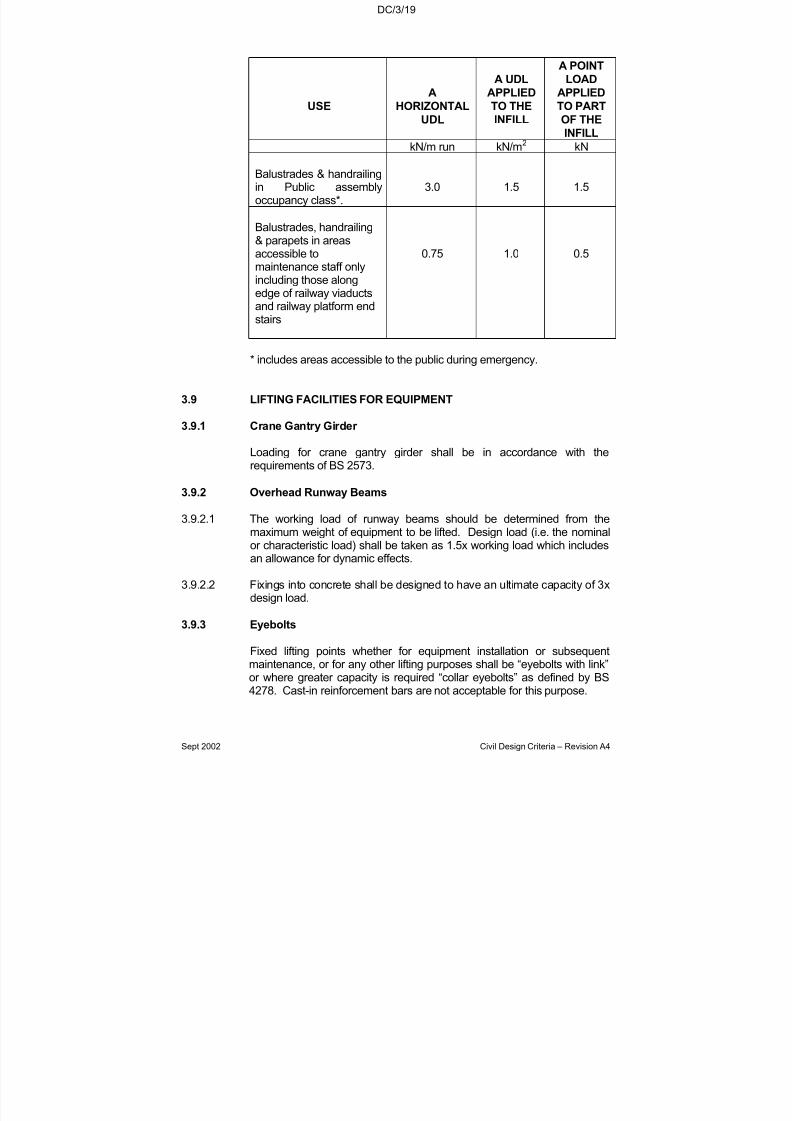
7/18/2019 LTA Civil_standards- Civil Design Criteria
http://slidepdf.com/reader/full/lta-civilstandards-civil-design-criteria 69/345
DC/3/19
Sept 2002 Civil Design Criteria – Revision A4
USE
A
HORIZONTAL
UDL
A UDL
APPLIED
TO THE
INFILL
A POINT
LOAD
APPLIED
TO PART
OF THE
INFILL
kN/m run kN/m2 kN
Balustrades & handrailingin Public assemblyoccupancy class*.
3.0 1.5 1.5
Balustrades, handrailing& parapets in areasaccessible tomaintenance staff onlyincluding those along
edge of railway viaductsand railway platform endstairs
0.75 1.0 0.5
* includes areas accessible to the public during emergency.
3.9 LIFTING FACILITIES FOR EQUIPMENT
3.9.1 Crane Gantry Girder
Loading for crane gantry girder shall be in accordance with therequirements of BS 2573.
3.9.2 Overhead Runway Beams
3.9.2.1 The working load of runway beams should be determined from themaximum weight of equipment to be lifted. Design load (i.e. the nominalor characteristic load) shall be taken as 1.5x working load which includesan allowance for dynamic effects.
3.9.2.2 Fixings into concrete shall be designed to have an ultimate capacity of 3xdesign load.
3.9.3 Eyebolts
Fixed lifting points whether for equipment installation or subsequentmaintenance, or for any other lifting purposes shall be “eyebolts with link”or where greater capacity is required “collar eyebolts” as defined by BS4278. Cast-in reinforcement bars are not acceptable for this purpose.
7/18/2019 LTA Civil_standards- Civil Design Criteria
http://slidepdf.com/reader/full/lta-civilstandards-civil-design-criteria 70/345
DC/3/20
Sept 2002 Civil Design Criteria – Revision A4
To give warning against impending failure, in the unlikely event of overload, eyebolts shall be designed using the following procedure toensure that yielding would occur before brittle failure of the base material.
3.9.3.1 Eyebolt selection/design: The safe working load of eyebolts for lifting or hauling shall be determined from the maximum weight of equipment to bemoved. Eyebolts shall be selected/designed in accordance with BS 4278
giving consideration to the effects of non axial loading. Proof loading,taken as 2x the safe working load, may be assumed to have included anallowance for dynamic effects.
3.9.3.2 The maximum angle between the eyebolt axis and the line of applicationof pull shall be co-ordinated with the System-wide Contractors and clearlyshown on the design drawings.
3.9.3.3 Local anchorage design: The anchorage capacity (e.g. pullout or conefailure) of the eyebolt fixing into the supporting member shall be designedto resist an ultimate load of 3x safe working load. In the case of concrete
beams or slabs, the fixing shall be effectively anchored to the top of thesupporting members using reinforcement links designed for this ultimateload.
3.9.3.4 Supporting Member design: Supporting structural elements (for exampleslabs, walls, beams, etc) shall be designed for a service load equal to thetest load and for an ultimate design load equal to the test load multipliedby a partial safety factor for load equal to at least 1.4. For the purpose of design, the test load shall be taken as not less than 1.5x safe workingload.
3.10 PARTIAL SAFETY FACTORS FOR LOADS
No reduction in partial safety factors from those recommended in therelevant standards shall be allowed, even where the relevant standardprovides guidance on the use of reduced or alternative partial safetyfactors, without the explicit approval of the Authority prior to the award of tender, or unless specifically stated otherwise in the Design Criteria. For example, the reduced load factors in SS CP 65 Part 2 Table 2.1 shall notbe used; rather those in Table 2.1 of SS CP 65 Part 1 shall be used.
3.11 SEISMIC LOADING
No allowance for seismic loading is required.

7/18/2019 LTA Civil_standards- Civil Design Criteria
http://slidepdf.com/reader/full/lta-civilstandards-civil-design-criteria 71/345
DC/3/21
Sept 2002 Civil Design Criteria – Revision A4
Chapter 3, Appendix 1
Design Parameters for Derailment
All design shall allow for the following minimum values of loads anddesign parameters due to derailment. The designer shall ascertain
whether more onerous values are appropriate, and, if so, shallincorporate such values into the design.
a) MRT
P1 (kN): 2000P2 (kN): 1000H1 (mm): 1100H2 (mm): 3500D1 (degrees): 6D2 (degrees): 10
P3 (kN): 4000H3 (kN): 1100
b) LRT
P1 (kN): 1000P2 (kN): 500H1 (mm): 1100H2 (mm): 3500D1 (degrees): 6D2 (degrees): 10
P3 (kN): 2000H3 (kN): 550
7/18/2019 LTA Civil_standards- Civil Design Criteria
http://slidepdf.com/reader/full/lta-civilstandards-civil-design-criteria 72/345

7/18/2019 LTA Civil_standards- Civil Design Criteria
http://slidepdf.com/reader/full/lta-civilstandards-civil-design-criteria 73/345
DC/4/2
Sept 2002 Civil Design Criteria – Revision A4
4.4.2 Ballasted Track
4.4.2.1 The track system for ballasted track shall be made up of mediumhardwood sleepers at 700mm spacing with a rail support whichconforms to internationally recognised standards. Alternative sleeper types shall be subject to the acceptance of the Authority. The railfastening system used may be of a non-insulated type if the insulation
provided by the timber sleeper is adequate, to meet the requirement of 4.5.1.
4.4.3 Slab Track
4.4.3.1 The track fastening used for the slab track shall be of an acceptedinternational standard with track support spacing at 700mm and shall becapable of delivering a static resilience of 30kN/mm/m. It will be insulatedand able to meet the requirements of clause 4.5.1. In addition, thesystem will provide an incremental vertical height adjustment of 14mmat each rail support.
4.4.3.2 Slab track shall be selected throughout the tunnels and depot exceptwhere there is a need to protect buildings sensitive to excessive noiseand vibration.
4.4.4 Noise and Vibration attenuating track
4.4.4.1 In specific areas of sensitivity to noise and vibration where theresilience characteristics of normal slab track are deemed to beinsufficient a special track form shall be provided. This will be of aninternationally recognised standard to the acceptance of the Authority.
4.4.5 Level Crossing
4.4.5.1 The rail fastening system used for level crossings in the depot areashall be of an insulated type in accordance with clause 4.4.3. The gapbetween the concrete and the rail shall be sealed with non-conductive,pre-formed elastomeric flangeway sealing section.
4.4.5.2 Alternatively the rail can be supported on a site installed elastomericcompound which provides resilience under the rail, lateral support andelectrical insulation between the rail and the concrete channel.
4.4.6 Noise and Vibration
4.4.6.1 Noise and vibration in buildings adjacent to the tunnels shall bepredicted. This prediction shall be based on the use of slab track andshall take into account: -
a) the details of the track design;b) the configuration and construction of the tunnel;c) the ground conditions;d) the structural arrangement of the building;

7/18/2019 LTA Civil_standards- Civil Design Criteria
http://slidepdf.com/reader/full/lta-civilstandards-civil-design-criteria 74/345
DC/4/3
Sept 2002 Civil Design Criteria – Revision A4
e) the mass, suspension characteristics and arrangement of therolling stock;
f) the design speed of the rolling stock.g) the operating condition of the rolling stock and the tracks
4.4.6.2 Where the predicted noise from the passage of a single train exceeds40 dB(A) peak, the use of the building shall be determined. Uses
sensitive to noise and vibration (includes residential properties) shall behigh-lighted and ambient conditions measured. Acceptable noise andvibration levels in sensitive use buildings shall be agreed between theDesigner and the Authority. A noise and vibration analysis shall beconducted along the proposed railway route. Where the acceptablenoise and vibration level is exceeded by the use of slab track, floatingslab or an alternative track form shall be installed in the tunnels for sufficient length either side of the sensitive building to reduce noise andvibration to an acceptable level. The extent of floating slab track shallbe rationalised to avoid an excessive number of changes from one typeof track to another. Transition lengths shall be incorporated to avoid an
abrupt change from slab track to floating slab track.
4.4.7 Space constraints
4.4.7.1 The track design shall be compatible with the space provided in bothtunnels and on viaducts.
4.4.7.2 The civil works contractor will install a depth of concrete in the base of the tunnel (stage 1 concrete). The trackworks contractor will install allworks above the stage 1 concrete. The depth of stage 2 concrete shallbe determined by the Designer.
4.4.8 Trackwork components
4.4.8.1 Rail components (rails, turnouts, crossings) shall conform to UICstandards. Further details of these can be found in the Materials andWorkmanship specification.
4.4.8.2 Rail shall be UIC 60. They shall be inclined at 1:40 to the verticalexcept at switch and crossing areas where the rail shall be vertical.
4.5 TRACK INSULATION
4.5.1 In general, adequate insulation is required to prevent current leakageto the track supporting structure and for proper functioning of thesignalling system. The track system shall achieve a minimum of 10ohm-km resistance between the track and the supporting structuremeasured in both dry and damp conditions, with newly laid track andwithout any other trackside equipment or cable installation attached. Themaximum rail to rail resistance when the track is dry shall not exceed2000 ohm-km.
7/18/2019 LTA Civil_standards- Civil Design Criteria
http://slidepdf.com/reader/full/lta-civilstandards-civil-design-criteria 75/345
DC/4/4
Sept 2002 Civil Design Criteria – Revision A4
4.6 MISCELLANEOUS
4.6.1 Cable Troughs
4.6.1.1 The size, length and location requirement of the pre-cast reinforcedconcrete cable trough shall be determined in co-ordination with theelectrical & mechanical designers. Wherever possible, cables shall be
placed in cable brackets installed on the walls of the tunnels or viaducts. The trackwork designer shall detail cable troughs mainly for the cables to cross the tracks. Owing to interference with ballasttamping, the installation of cable troughs parallel to the tracks or crossing the tracks within turnouts shall be avoided as far as possible.
4.6.1.2 Cable trough crossing the track shall be placed perpendicular to thetrack. The placing of troughs in the adjacent sleeper space is notpermitted. The top surface of the trough shall be level with the topsurface of the adjacent sleepers.
4.6.2 Buffer Stops
4.6.2.1 The buffer stops shall be of the sliding friction type and located at theend of the tracks. They shall be able to stop the train on impact at adeceleration rate of 0.15g for tracks where trains will be carryingpassengers and 0.22g for tracks where trains will not carry passengers,with a maximum track occupancy of 12m. The considered speed for buffer stop design shall be the speed protected by the signallingsystem.
4.6.3 Over-Voltage Protection Devices (OVPDs)
4.6.3.1 The Over-Voltage Protection Devices shall be the self re-settable typeand provided to avoid excessive contact voltages at insulated rails of track circuits and also across Insulated Rail Joint (IRJ) provided for sectionalising the traction return. The provision of these devices shallbe determined in co-ordination with the signalling designer. The OVPDshall have an appropriate fusing voltage and be installed betweennegative return rail and signalling rail for the insulated rail section. Thedevice provided shall be compatible with the return voltage.
4.6.4 Reference Points and Distance Indicators
4.6.4.1 Reference Points shall be placed at fixed points alongside the trackand generally at 10m interval in plain line. They shall contain thefollowing data: -
Distance (chainage value)Level
Alignment point (BC, EC, etc)Offset (Distance to nearest gauge face of running rail)Cant Value

7/18/2019 LTA Civil_standards- Civil Design Criteria
http://slidepdf.com/reader/full/lta-civilstandards-civil-design-criteria 76/345
DC/4/5
Sept 2002 Civil Design Criteria – Revision A4
4.6.4.2 Distance Indicators are required at every 50 m in tunnel and at 100 moutside tunnels. These are to be manufactured from work-hardenedaluminium sheets faced with high-intensity reflective film. The chainagevalues in black are to be superimposed on the reflective film. Theplates are to be mounted on the tunnel walls and viaduct parapets.
4.6.5 Cross-Bonding and Jumper Cables
4.6.5.1 For bridging insulated sections of the running rail in order to ensure theflow of the negative return current, cross-bonding cables and jumper cables are required.
4.6.5.2 The installation locations shall be co-ordinated and determined incollaboration with the Signal and Power Designers. In general, jumper cables shall be installed at all turnouts and interrupted rails on either side of the insulated sections. The method of cable connection to therunning rail shall be subject to the authorities approval.
4.6.6 Bonded Insulated Rail Joint
4.6.6.1 All bonded insulated rail joints shall be factory-made and welded into thetrack.
4.6.6.2 The insulated rail joint (IRJ) is to separate electrically two adjacentrunning rail sections and shall have minimum electric resistance of 1000 ohm for a thoroughly moistened joint. The location shall bedetermined by the Signal Designer.
4.6.6.3 The joint shall be of the glued synthetic-resin type with steel fishplates
and high tensile bolts and successfully installed for UIC 60 rail with amajor railway system for a minimum of 5 years.
4.6.7 Welding
4.6.7.1 Rail for all main line tracks outside the limits of turnouts shall be weldedinto continuous strings using the electric flash-butt welding process usingan on-track machine
4.6.7.2 Rail within turnout limits may be welded using an accepted thermitwelding process.
4.6.8 Trap points
4.6.8.1 Trap points shall be provided on all reception tracks with a downhillgradient from sidings to passenger carrying lines. They shall also beprovided at all centre siding locations.

7/18/2019 LTA Civil_standards- Civil Design Criteria
http://slidepdf.com/reader/full/lta-civilstandards-civil-design-criteria 77/345
DC/4/6
Sept 2002 Civil Design Criteria – Revision A4
4.7 Third Rail System
4.7.1 General
4.7.1.1 The third rail system shall be of the bottom contact type in which vehicle-mounted current collection shoes press upwards onto the underside of the conductor rail.
4.7.1.2 The third rail shall be provided with a continuous insulating cover toprotect persons from accidental contact with the third rail and protect thethird rail from foreign objects falling or being thrown onto it.
4.7.1.3 All fastenings shall be of stainless steel minimum grade A4-80 forging of stainless steel components shall be prohibited
4.7.2 Conductor Rail
4.7.2.1 The conductor rail shall be manufactured from a high-conductivity
aluminium alloy with a stainless steel wearing face and shall be to thedimensions shown on the drawings. The stainless steel shall be joined tothe aluminium by a molecular or welding process and not by mechanicalmeans alone. The rail shall be supplied to site straight and in standardlengths.
4.7.3 Joints in the Conductor Rail
4.7.3.1 Individual lengths of conductor rail shall be rigidly connected to eachother, both mechanically and electrically, using splice plates made fromthe same aluminium alloy as the rail.
4.7.4 Ramps
4.7.4.1 Entry and exit ramps shall be provided at turnouts and at other locationswhere a gap in the conductor rail is necessary. They shall also beprovided at all electrical disconnecting points and changes of the third railinstallation from one side of the track to the other. The ramp designshould take into account the differing requirements of high and low speedtrain running.
4.7.5 Conductor Rail Supports
4.7.5.1 Conductor rails shall be supported at intervals which are sufficiently smallto ensure that nowhere will the conductor rail deflection exceeds 6mmfrom the design level.
4.7.6 Protective Cover
4.7.6.1 The materials used for the protective cover shall be unplasticizedpolyvinyl chloride (UPVC) for use outside tunnels and glass fibrereinforced plastic (GF-RP) inside tunnels. Outside tunnels, the coversshall be resistant to degradation due to prolonged exposure to sunlight.

7/18/2019 LTA Civil_standards- Civil Design Criteria
http://slidepdf.com/reader/full/lta-civilstandards-civil-design-criteria 78/345
DC/4/7
Sept 2002 Civil Design Criteria – Revision A4
Exact materials specifications shall be proposed by the Contractor for acceptance by the Engineer.

7/18/2019 LTA Civil_standards- Civil Design Criteria
http://slidepdf.com/reader/full/lta-civilstandards-civil-design-criteria 79/345
DC/5/1
Sept 2002 Civil Design Criteria – Revision A4
CHAPTER 5
GEOTECHNICAL PARAMETERS
5.1 GENERAL
The Geotechnical design parameters and other requirements/information given in this chapter have been derived from various LTAprojects. The Contractor shall use these together with the results of thesoil investigation for the Project. For any relaxation of the minimumrequirements given in this Chapter, the Contractor shall obtain theEngineer's prior approval by showing convincing data from soilinvestigations.
5.2 HYDROGEOLOGY
5.2.1 Rainfall
Mean monthly rainfall values for Singapore are given below:
Month Jan Feb Mar Apr May Jun
Rainfall, mm 250 180 190 190 170 170
Month Jul Aug Sept Oct Nov Dec
Rainfall, mm 170 200 180 210 250 260
5.2.2 Design Ground Water Levels
In the design of underground structures, Design Ground Water Levelshall be assumed to be at existing ground level or at proposed finalbackfill level, whichever is higher.
A further factor in the design for groundwater pressure is the floodingwhich occurs in the river valleys. Major floods in Singapore may persistfor up to a day. Therefore, underground structures constructed by cutand cover techniques could be subject to hydrostatic pressure to floodlevel (please refer to Chapter 3 of the Design Criteria).
7/18/2019 LTA Civil_standards- Civil Design Criteria
http://slidepdf.com/reader/full/lta-civilstandards-civil-design-criteria 80/345

7/18/2019 LTA Civil_standards- Civil Design Criteria
http://slidepdf.com/reader/full/lta-civilstandards-civil-design-criteria 81/345
Sept 2002 Civil Design Criteria – Revision A4
DC/5/3
TABLE 5/1: DESCRIPTION OF SOIL AND ROCK TYPES
REFERENCE SOIL & ROCK
TYPE
GENERAL
DESCRIPTION
GEOLOGICAL
FORMATION
(PWD, 1976)
B
E
F
F1
F2
M
O
S3
BEACH(Littoral)
ESTUARINE(Transitional)
FLUVIAL(Alluvial)
MARINE
OLD ALLUVIUM
BOULDER BED(Colluvial)
Sandy, sometimes silty,with gravels, coral andshells.
Peats, peaty andorganic clays, organicsands.
Sands, silty sands, siltsand clays.
Predominantly granular soils including siltysands, clayey sandsand sandy silts.
Cohesive soilsincluding silty clays,
sandy clays and clayeysilts.
Very soft to soft blue or grey clay.
Silty sand to silty clay.
A colluvial deposit of boulders in a soilmatrix. The matrix is
typically a hard siltyclay, but can begranular. The materialis largely derived fromthe rocks andweathered rocks of theJurong Formation.
KALLANG Littoral,possibly also part of allother members &TEKONG
KALLANG Transitional,possibly part of Alluvialand Marine.
KALLANG Alluvial,possibly part of all other members and TEKONG.
KALLANG MarineMember.
OLD ALLUVIUM

7/18/2019 LTA Civil_standards- Civil Design Criteria
http://slidepdf.com/reader/full/lta-civilstandards-civil-design-criteria 82/345
Sept 2002 Civil Design Criteria – Revision A4
DC/5/4
Table 5.1 Cont’d
REFERENCE SOIL & ROCK
TYPE
GENERAL
DESCRIPTION
GEOLOGICAL
FORMATION(PWD, 1976)
S
S1
S2
S4
S4a
S4b
G
G1
SEDIMENTARIES(Rocks &associated soils)
GRANITE (Rock
and associatedResidual soils)
Sandstones, siltstonesand mudstones.
Fresh to slightlyweathered rock(Weathering Grades Iand II)
Moderately to highlyweathered rock(Weathering Grades III& IV).
Completely weatheredrock or residual soil(Weathering Grades V& VI).
Silty, sandy weak rockor partially indurated,very dense, pre-dominantly granular soils.
Fine grained weak rockor partially indurated,hard, cohesive soils.
Fresh to slightly
weathered rock(Weathering Grades I& II).
Moderately to highlyweathered rock(Weathering Grades III& IV).
JURONG Tengah,Rimau, Ayer Chawanand Queenstown Facies.
BUKIT TIMAH GRANITE
7/18/2019 LTA Civil_standards- Civil Design Criteria
http://slidepdf.com/reader/full/lta-civilstandards-civil-design-criteria 83/345
Sept 2002 Civil Design Criteria – Revision A4
DC/5/5
Table 5.1 Cont’d
REFERENCE SOIL & ROCK
TYPE
GENERAL
DESCRIPTION
GEOLOGICAL
FORMATION
(PWD, 1976)
G2
G3
G4
Moderately to highlyweathered rock(weathering Grades III& IV).
Bouldery soil: Bouldersof rock of variableweathering within itsweathered by-product.
Completely weatheredrock or residual soil(Weathering Grades V& VI).

7/18/2019 LTA Civil_standards- Civil Design Criteria
http://slidepdf.com/reader/full/lta-civilstandards-civil-design-criteria 84/345
Sept 2002 Civil Design Criteria – Revision A4
DC/5/6
TABLE 5/2 : ROCK WEATHERING CLASSIFICATION(AFTER ANON, 1970)
GEOLOGICAL
CLASSIFICATION GRADE DESIGNATION SYMBOL DESCRIPTION
S1 & G1
IA
IB
II
Fresh
FaintlyWeathered
SlightlyWeathered
F
FW
SW
No visible sign of weathering.
Weathering limited to thesurface of major discontinuities.
Penetrative weatheringdeveloped on opendiscontinuity surfaces
but only slightweathering of rockmaterial.
S2 & G2
III
IV
ModeratelyWeathered
Highly
Weathered
MW
HW
Weathering extendsthroughout the rockmass but the rockmaterial is not friable.
Weathering extends
throughout rock massand the rock material isfriable.
S4 & G4
V
VI
CompletelyWeathered
Residual Soil
CW
RS
Rock is wholly de-composed and in afriable condition but therock texture andstructure are preserved.
A soil material with theoriginal texture, structureand mineralogy of therock completelydestroyed.
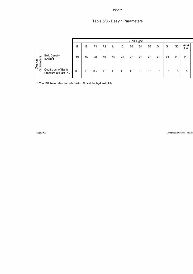
7/18/2019 LTA Civil_standards- Civil Design Criteria
http://slidepdf.com/reader/full/lta-civilstandards-civil-design-criteria 85/345
DC/5/7
Sept 2002
Table 5/3 - Design Parameters
Soil Type
B E F1 F2 M O S3 S1 S2 S
Bulk Density(kN/m3)
19 15 20 19 16 20 22 23 22 2
D e s i g n
P a r a m e t e r s
Coefficient of EarthPressure at Rest (K0 ) 0.5 1.0 0.7 1.0 1.0 1.0 1.0 0.8 0.8 0
* The ‘Fill’ here refers to both the top fill and the hydraulic fills.
7/18/2019 LTA Civil_standards- Civil Design Criteria
http://slidepdf.com/reader/full/lta-civilstandards-civil-design-criteria 86/345
DC/5/8
Sept 2002 Civil Design Criteria – Revision A4
5.5 SOIL AND GROUNDWATER CHEMISTRY
A summary of soil and groundwater investigation results obtained fromvarious LTA projects is given in Table 5/4 for guidance. These may bestudied together with the chemical test results obtained during the soilinvestigation for the Project.
The classification system to be adopted for the design, in relation tochemical properties of soil and groundwater, is given in Table 5/5. Thisshall be used in conjunction with the recommendations of BS 5328 anddata from investigations at actual site locations.
5.6 SITE INVESTIGATION
A site investigation may be conducted by the Contractor to justify anychanges to the parameters given in Table 5/3 and Table 5/4 of this
chapter as well as to obtain reliable information for an economic and safedesign and to meet the tender and construction requirement.
The data collected shall be of sufficient quantity and quality to enable thefollowing analysis to be carried out where appropriate:
a) Shallow and deep foundations
• ultimate and allowable bearing capacities of soils for shallowfoundations;
• ultimate and allowable vertical bearing capacities for deep
foundations including the evaluation of negative skin friction;
• ultimate and allowable lateral bearing capacities for deepfoundations;
• settlement estimates for shallow and deep foundations; and
• settlement estimates for effects of dewatering.
b) Temporary and permanent retaining structures
• stability and deformation analyses; and
• evaluation of bracing or anchoring system;
c) Underground structures
• settlement estimates for bored tunnelling, including NATM;
• evaluation of methods of building protection;

7/18/2019 LTA Civil_standards- Civil Design Criteria
http://slidepdf.com/reader/full/lta-civilstandards-civil-design-criteria 87/345
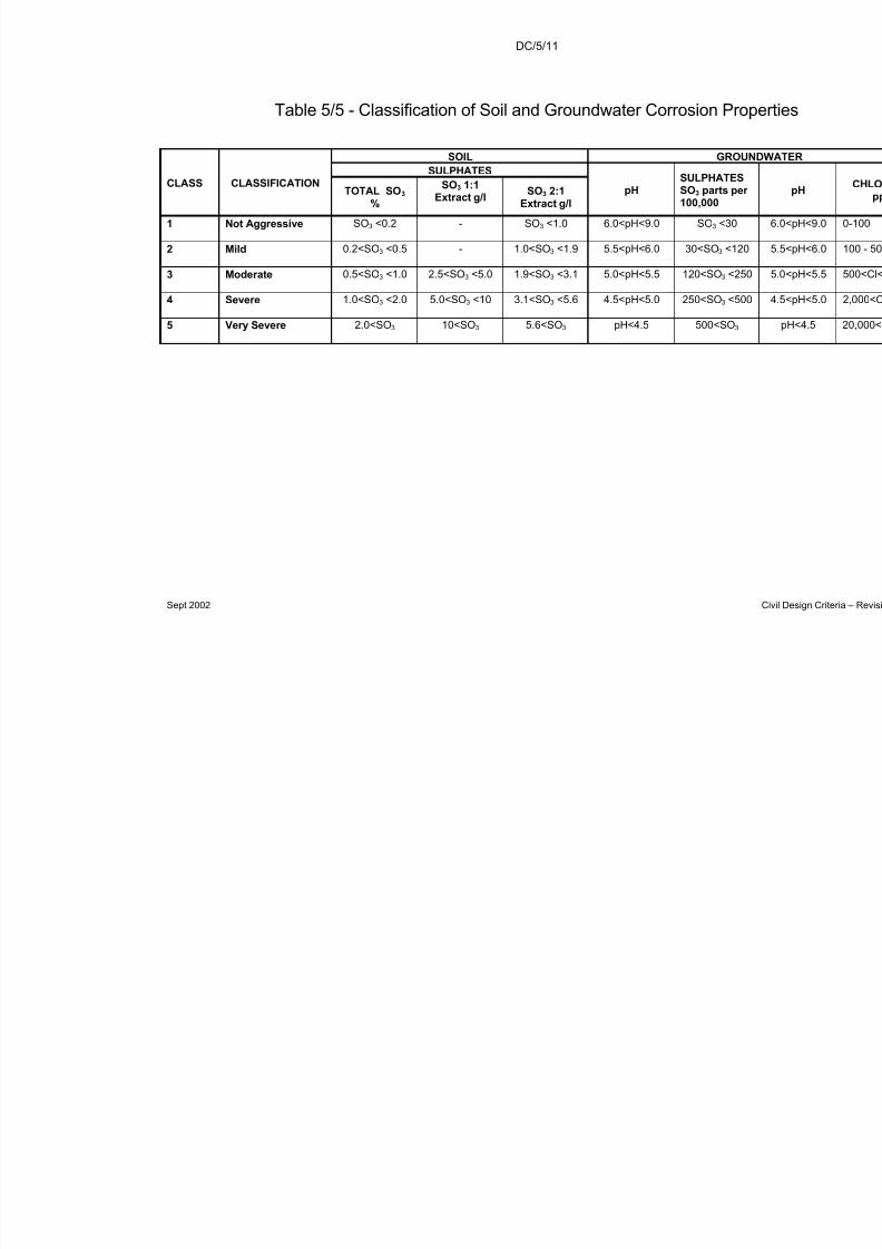
7/18/2019 LTA Civil_standards- Civil Design Criteria
http://slidepdf.com/reader/full/lta-civilstandards-civil-design-criteria 88/345
DC/5/11
Sept 2002
Table 5/5 - Classification of Soil and Groundwater Corrosion P
SOIL GSULPHATES
CLASS CLASSIFICATIONTOTAL SO3
%
SO3 1:1Extract g/l
SO3 2:1Extract g/l
pHSULPHATSO3 parts100,000
1 Not Aggressive SO3 <0.2 - SO3 <1.0 6.0<pH<9.0 SO3 <
2 Mild 0.2<SO3 <0.5 - 1.0<SO3 <1.9 5.5<pH<6.0 30<SO3
3 Moderate 0.5<SO3 <1.0 2.5<SO3 <5.0 1.9<SO3 <3.1 5.0<pH<5.5 120<SO3
4 Severe 1.0<SO3 <2.0 5.0<SO3 <10 3.1<SO3 <5.6 4.5<pH<5.0 250<SO3
5 Very Severe 2.0<SO3 10<SO3 5.6<SO3 pH<4.5 500<S
7/18/2019 LTA Civil_standards- Civil Design Criteria
http://slidepdf.com/reader/full/lta-civilstandards-civil-design-criteria 89/345
DC/6/1
Sept 2002 Civil Design Criteria – Revision A4
CHAPTER 6
FOUNDATIONS, EARTHWORKS
AND PERMANENT RETAINING STRUCTURES
6.1 INTRODUCTION
6.1.1 General
This Chapter covers the requirements for the design of foundations,earthworks and permanent retaining structures. The design of temporary retaining structures shall be in accordance with therequirements of Chapter 8.
All design shall comply with BS 5400, BS 6031, BS 8002, BS 8004, BS8006, and SS CP 65 unless otherwise modified by subsequent sectionsof this Chapter or unless otherwise accepted by the Engineer. In
designing timber piles the requirements of SS CP7 shall be followed.
The foundations, earthworks and retaining structures shall be designedfor both short term and long term conditions.
6.1.2 Ground Movements
Design of foundations, earthworks and retaining structures shall takeinto consideration all possible ground movements, ground conditionsand groundwater levels. The design shall ensure that movements arewithin limits that can be tolerated by the Works without impairing the
function, durability and aesthetic value of the Works.
It shall be demonstrated that the chosen foundation system does notresult in differential settlements that will have a significant influence oneither the Works as a whole or on individual or groups of elements inthe Works.
It shall be demonstrated that the chosen foundation system or form of construction shall not result in excessive settlement of adjoiningproperties, structures or utilities as specified in Chapter 20.
6.1.3 Deleterious Substances in Soils
Substances in soils and ground water, which are potentially deleteriousto materials used in buried structures, shall be considered in the designand specification of all such structures. Buried structures shall beconsidered as critical elements in the selection of materials and in thespecification of any protection system. Buried structures shall includebut not necessarily be limited to foundations and that face of a retainingstructure which is in contact with the ground.
7/18/2019 LTA Civil_standards- Civil Design Criteria
http://slidepdf.com/reader/full/lta-civilstandards-civil-design-criteria 90/345
DC/6/2
Sept 2002 Civil Design Criteria – Revision A4
6.1.4 Combining Foundation Types in a Single Structure
A combination of different foundation types or systems within a singlestructure shall not be permitted without the prior acceptance of theEngineer.
6.2 DESIGN REQUIREMENTS FOR FOUNDATIONS
6.2.1 Shallow Foundations
6.2.1.1 General
Shallow foundations may be used where there is a suitable bearingstratum at founding level. Where compressible or loose soil layersoccur below the founding stratum, deep raft foundations or DFEs shallbe used unless otherwise accepted by the Engineer.
6.2.1.2 Settlement
The maximum allowable settlement of shallow foundations shall be inaccordance with Section 6.3, Table 6.1.
6.2.1.3 Allowable Bearing Capacity
When determining the allowable bearing capacity, a factor of safety of 3 against ultimate shear failure shall be applied to dead loads alone.This may be reduced to 2.5 when applied to dead plus live loads.
6.2.1.4 Groundwater Level
The groundwater level shall be considered to be at finished groundlevel for assessing the allowable bearing capacity of a shallowfoundation.
6.2.1.5 Influence of Adjacent Foundations
Where the pressure beneath a foundation is influenced by adjacentfoundations, a detailed settlement analysis must be made and theallowable bearing pressure adjusted to ensure that the maximum
allowable and differential settlements are not exceeded.
6.2.1.6 Foundations on Slopes
Shallow foundations shall not be designed on or near slopes unlessaccepted by the Engineer. Where it is acceptable the followingadditional analyses are required:
a) Stability of the slope.
b) Allowable bearing capacity of the foundation on the slope.
7/18/2019 LTA Civil_standards- Civil Design Criteria
http://slidepdf.com/reader/full/lta-civilstandards-civil-design-criteria 91/345
DC/6/3
Sept 2002 Civil Design Criteria – Revision A4
6.2.2 Deep Raft Foundations
6.2.2.1 General
Deep raft foundations shall include but not necessarily be limited to thebase slabs of cut and cover tunnels and stations where the base slab isnot wholly supported by deep foundation elements. Deep raft
foundations may be used where there is a suitable bearing stratum atformation level with no compressive or loose soil layers below andwhen predicted settlements are acceptable to the Engineer. Wherethere are weak or compressible materials existing at formation level or below the bearing stratum DFEs shall be used.
6.2.2.2 Settlement
The maximum allowable settlement of the raft shall be in accordancewith Section 6.3, Table 6.1.
6.2.2.3 Allowable Bearing Capacity
When determining the allowable bearing capacity a factor of safety of 3against ultimate shear failure shall be applied to dead loads alone. Thismay be reduced to 2.5 when applied to dead plus live loads.
6.2.2.4 Methods of Analysis
Settlement analyses shall be carried out by using either Finite Elementor Finite Difference methods. Suitable alternative methods may beused to the acceptance of the Engineer.
Where values for the subgrade modulus are used in the calculations,the values shall be confirmed by FE or FD analyses for an appropriaterange of foundation geometries.
In addition to elastic settlements, consideration shall be given to thepotential for non-elastic settlements such as those due to creep andconsolidation.
6.2.2.5 Negative Skin Friction
Negative skin friction shall be considered in the design in marine soils,alluvial soils, estuarine soils, made ground and any other material thatis prone to consolidation or is to be consolidated.
Computation of negative skin friction shall be by effective stressanalysis
7/18/2019 LTA Civil_standards- Civil Design Criteria
http://slidepdf.com/reader/full/lta-civilstandards-civil-design-criteria 92/345
DC/6/4
Sept 2002 Civil Design Criteria – Revision A4
6.2.3 Deep Foundation Elements (DFEs)
6.2.3.1 General
The term Deep Foundation Element (DFE) shall include all foundationelements designed to transfer loads by shaft friction and/or endbearing. These elements shall include but not be limited to piles, pile
groups, diaphragm walls, barrettes, secant and contiguous bored pilewalls and all other similar load bearing structures. In the event of anyuncertainty as to whether or not a particular foundation type or elementis covered by this definition written clarification shall be sought from theEngineer. The Engineer’s decision shall be final and binding.
Deep foundation elements shall be used where other types of foundations are not suitable.
When choosing the type of foundation consideration shall be given tothe impact of noise and vibration during DFE installation and current
legislation on the use of piling and other construction equipment.
For cast in situ DFEs the minimum grade of concrete used shall beG30.
Timber piles shall be permitted only for lightly loaded structures to theacceptance on the Engineer.
In designing precast piles and pile joints, stresses arising from impactand shock from piling hammers shall be considered.
6.2.3.2 Settlement
The maximum allowable foundation settlement shall be in accordancewith Section 6.3, Table 6.1
Settlement calculations shall take in to account both short term andlong term settlements and shall include inter alia immediate (non-recoverable), elastic, consolidation and creep settlements both at theDFE/soil interface and within the DFE itself.
6.2.3.3 Negative Skin Friction
Negative skin friction shall be considered in the design in marine soils,alluvial soils, estuarine soils, made ground and any other material thatis prone to consolidation or is to be consolidated.
Computation of negative skin friction shall be by effective stressanalysis.
Raking DFEs shall not be used in areas where negative skin friction isanticipated unless the Engineer gives prior acceptance.
7/18/2019 LTA Civil_standards- Civil Design Criteria
http://slidepdf.com/reader/full/lta-civilstandards-civil-design-criteria 93/345
DC/6/5
Sept 2002 Civil Design Criteria – Revision A4
6.2.3.4. Working Loads
The working loads of the DFE shall be the greater of:
(1) Applied dead load + Negative skin friction and non-transient liveload.
(2) Applied dead load + total live load.
6.2.3.5 Lateral Loads
Where lateral loads are anticipated, the DFE shall satisfy therequirements given in Table 6.1. The analysis shall use “p-y” curve,finite element or finite difference. The use of such a method shall besubject to prior acceptance by the Engineer.
6.2.3.6. Ultimate Bearing Capacity
The size of the DFE shall be demonstrated to be sufficient to providethe required bearing capacity and meet the settlement criteria. Totalstress analysis and effective stress analysis shall be carried out withthe more critical of the two adopted.
The overall factor of safety on working loads shall be not less than 2.5,unless otherwise accepted by the Engineer. In addition the factor of safety shall be not less than 1.5 in shaft friction alone, except in thefollowing cases:
Case a. When the DFE has been installed by drivingCase b. Where there is safe man access to the base of the DFE,
any loose or remoulded material is removed from thebase, and the base inspected and confirmed dry beforecasting the concrete
Case c. If the DFE is base grouted, using a proven method of base grouting to the satisfaction of the Engineer.
Case d. Where the end bearing is provided by S1 or G1 rock, andtoe coring is carried out to confirm the pile/rock contactfor every DFE.
If the design is based on any of these four cases, the appropriaterequirements for driving, access and inspection, base grouting or toecoring must be included on the loading plan drawings. The designer may specify which of the cases is to be used, or may allow thecontractor the option of selecting from two or more of these cases.The DFE design shall be verified by Preliminary Load Testing.
7/18/2019 LTA Civil_standards- Civil Design Criteria
http://slidepdf.com/reader/full/lta-civilstandards-civil-design-criteria 94/345
DC/6/6
Sept 2002 Civil Design Criteria – Revision A4
6.2.3.7. DFE Interaction
The failure of a DFE group shall be checked in settlement and inbearing capacity. The interaction between DFEs shall be assessed andconsidered in the calculation of the capacity and settlement based onPoulos and Davis (1) or other method accepted by the Engineer.
6.2.3.8 DFEs Acting in Tension
The factor of safety against failure shall be demonstrated to be not lessthan 3.5 if the skin friction is derived from preliminary DFE tests carriedout in compression. In addition, for driven piles the ultimate skin frictionunder tension shall be taken as no more than 75% of the ultimatefriction measured in compression. No reduction factor is required for bored piles.
Where the skin friction is derived from preliminary DFE tests with theDFE loaded in tension, then a factor of safety of 2.5 shall be used.
DFE groups under tension loading shall be checked for:
a) The sum of the uplift resistance of the individual DFEs, allowingfor interaction effects.
b) The sum of the shear resistance along the perimeter of thegroup and the effective weight of the soil and DFEs within theperimeter.
All structural connections shall be designed for the design tensile forcewith appropriate factors of safety.
6.2.3.9 Effect of Future Developments
In addition to the calculated vertical and lateral loads, the designer shallallow for the effects of future developments; to do this, he shalldemonstrate that the DFEs are designed to allow for movements of 15mm in any plane at the junction of the DFE and the structure.
6.2.3.10 The structural design of DFEs shall meet the following requirements:
a) Pure Compressive Axial Load
Concrete/reinforced concrete DFEs subject to axial load onlyshall be designed such that average compressive stressesacross the whole section of the DFE at serviceability limit stateshall not exceed 0.25 times the characteristic cube strength of concrete at any point along the DFE. The designer may proposeto increase the allowable compressive stress for piles that areprovided with a permanent casing, to the acceptance of theEngineer.
7/18/2019 LTA Civil_standards- Civil Design Criteria
http://slidepdf.com/reader/full/lta-civilstandards-civil-design-criteria 95/345
DC/6/7
Sept 2002 Civil Design Criteria – Revision A4
b) Axial Load with Coexistent Lateral Load
Concrete/reinforced concrete DFEs shall be checked at both theultimate and serviceability limit states. In addition, concretebored piles subjected to both vertical and lateral loads shall bedesigned such that maximum combined bending andcompressive stresses at the extreme fibre, for the whole length
of the pile under working load condition shall not exceed 0.3times the characteristic cube strength of the concrete. Theaverage combined bending and compressive stresses acrossthe whole section shall not exceed 0.25 times the characteristiccube strength of the concrete.
c) Pure Tensile Axial Load
The safe tensile axial working load of the DFE shall bedetermined by multiplying the cross-sectional area of steelreinforcement with the permissible tensile stress in high yield
steel reinforcement. The permissible tensile stress under working load condition (serviceability limit states) shall be130N/mm2 for deformed, type 2, grade 460 bars. The DFE shallbe reinforced to the depth necessary to mobilise the requiredultimate skin friction capacity in tension. Laps shall be avoidedwherever possible. Where laps are necessary they shall be fullstrength laps assuming the reinforcement is working at theultimate limit state at full design strength (i.e. characteristicstrength of reinforcement divided by the partial safety factor for reinforcement).
d) The durability assessment shall demonstrate how the durabilityof DFEs will be achieved over the design life of the structure.The minimum condition of exposure per SS CP 65 Table 3.2
shall be taken as ‘severe’, except where more onerousconditions are required elsewhere (such as in Chapter 8).Particular consideration shall be given to:
• Where the DFE is in tension in any area that is in directcontact with fill or made ground
• Where the DFE is subject to wetting and drying cycles due tofluctuating water levels
• The chemistry of the ground and water around the DFEs.
Where the durability assessment demonstrates that durability of the DFE is of concern, then suitable measures shall be taken toimprove the durability. Measures to be considered would includeone or more of: sacrificial concrete, sacrificial outer casing,protection to the reinforcement, cathodic protection, or other suitable measures

7/18/2019 LTA Civil_standards- Civil Design Criteria
http://slidepdf.com/reader/full/lta-civilstandards-civil-design-criteria 96/345
DC/6/8
Sept 2002 Civil Design Criteria – Revision A4
6.3 SETTLEMENT/HEAVE
In the following section, the limits given for settlement and differentialsettlement shall also be complied with in terms of heave and differentialheave.
6.3.1 General
The maximum allowable foundation settlement shall be in accordancewith Table 6.1.
Maximum Allowable Settlement
Total DifferentialFoundation Type
Short Term Long Term Short Term Long Term
Shallow 20mm* 20mm* 1:1000* 1:1000*
Deep Raft 20mm* 20mm* 1:1000* 1:1000*
Deep Foundation Element 15mm 25mm 1:1000 1:1000
Laterally Loaded DFEs(Maximum Allowable HorizontalDeflections)
15mm 25mm 1:1000 1:1000
Table 6.1: Maximum Allowable Settlements and Differential Settlements
6.3.2. Settlement shall be the settlement occurring from the time at which thebase slab is cast and shall be measured at the structural surface of thebase slab.
6.3.3 Where the limits in Table 6.1 are marked with an asterisk (*), theselimits may be exceeded if it is demonstrated that the structure isdesigned for the movements to which it will be subjected and, whereappropriate, the limits on track or road movements given below.
6.3.4 Where the foundations provide support to structures carrying railwaytrack, the maximum anticipated settlement and differential settlement of
the railway track shall be calculated. The settlement calculation shallinclude the effects of all anticipated loads and effects occurring after the track has been laid. These shall include (but not be limited to): liveloads, any dead loads not applied prior to track laying, groundwater recovery, negative skin friction, known future development loads(including dewatering during such developments), creep of the materialforming the foundation, and creep and/or consolidation of the foundingstrata. The design shall ensure that the settlement of the track under these loads and effects does not exceed 15mm and that differentialsettlement of the track or its plinth does not exceed 1:1000 in anyplane.
7/18/2019 LTA Civil_standards- Civil Design Criteria
http://slidepdf.com/reader/full/lta-civilstandards-civil-design-criteria 97/345
DC/6/9
Sept 2002 Civil Design Criteria – Revision A4
6.3.5 Where the foundations provide support to a road, or structures carryinga road, the maximum anticipated settlement and differential settlementof the road shall be calculated. The design shall ensure that thesettlement and differential settlement do not adversely affect thefunction of and maintenance requirements for the road. Considerationshall be given to all aspects of the road, including, but not limited to:
the road pavement, drains, sumps, ancillary structures, mechanical andelectrical plant, cabling and services.
6.3.6 The assumptions with respect to backfill and recovery of the water table level before the track is laid in order that the limits on trackmovement can be met shall be justified, shall take account of theprogramme key dates at the time of design, and shall be stated on thedrawings.
6.3.7 Settlement is measured at any location along the track as the changeof the level of the track (where the track level is taken as the mean
level of the two rails). Differential settlement is measured in twodirections, as follows:
• Perpendicular to the track - 1:1000 between the rail headsmeasured as the difference in the change of levels between the tworails (mm) at that location divided by a nominal gauge of 1435 mm
• Parallel to the track - 1:1000 between any two points 3 metresapart, measured as the difference in the change of levels betweenthe two points (mm) divided by 3000 mm.
6.3.8 Short-term settlement shall consist of immediate non-recoverable
settlement, elastic settlement and consolidation settlement whichoccurs between the date of casting and the date of SubstantialCompletion of that part of the works.
6.3.9 Long-term settlement shall consist of immediate non-recoverablesettlements, elastic settlements, consolidation settlement from the dateof casting to the end of the design life and creep settlements from thedate of casting to the end of the design life.
6.3.10 For lateral loading maximum allowable deflections shall be calculatedat pile cut-off level.
6.4. DEBONDING OF PILES AND DEEP FOUNDATIONS
6.4.1 Where the Contract requires the DFEs to support loads from adjacentstructures then the permanent works shall be designed for the loadsimposed by the DFEs unless the DFEs are debonded such that there isno load transfer.
6.4.2 If it is chosen to design the permanent works for the imposed load fromthe DFEs, then it is required that the assumptions for load transfer along the length and at the base of the DFEs are verified by means of
7/18/2019 LTA Civil_standards- Civil Design Criteria
http://slidepdf.com/reader/full/lta-civilstandards-civil-design-criteria 98/345
7/18/2019 LTA Civil_standards- Civil Design Criteria
http://slidepdf.com/reader/full/lta-civilstandards-civil-design-criteria 99/345
DC/6/11
Sept 2002 Civil Design Criteria – Revision A4
For Driven Piles
a) The maximum settlement at working load (second cycle) exceeds 9mm.
b) The maximum settlement at 150% working load exceeds 20 mm.
For all DFEs
a) Failure of the DFE materials (due to defects in the DFEs).
b) Failure of concrete to reach the design compressive strength.
c) The residual settlement upon the final release of the load exceeds5 mm.
6.5.2 Preliminary Load Tests
a) Test Loads
The target for the preliminary load testing is to achieve the ULScriterion.
b) Dimensions for Preliminary Load Tests of DFEs
Preliminary load tests on piles can be considered representative for working piles up to twice the diameter of the preliminary test piles,provided that they are installed in similar ground conditions.
For the load testing of barrettes and diaphragm wall, the contractor may propose the testing of piles in place of the barrettes or diaphragmwall. However, the contractor must ensure that the diameter of the pileis at least equal to the minimum dimension of the diaphragm wall or barrette and that the method of construction for the pile is as similar aspossible to the diaphragm wall or barrette construction.
c) Ground Conditions
Preliminary test DFEs shall be installed in ground similar to that wherethe working DFEs are to be installed.
6.5.3 Working Load Tests
6.5.3.1 Test Loads
The test loads in a Working Load Test shall be 150% of the workingload of the DFEs.
6.5.3.2 Failure of Working Load Testing A DFE is considered to have failed a loading test if it does not complywith either of the SLS criteria. Where a pile fails the test the contractor

7/18/2019 LTA Civil_standards- Civil Design Criteria
http://slidepdf.com/reader/full/lta-civilstandards-civil-design-criteria 100/345

7/18/2019 LTA Civil_standards- Civil Design Criteria
http://slidepdf.com/reader/full/lta-civilstandards-civil-design-criteria 101/345
DC/6/13
Sept 2002 Civil Design Criteria – Revision A4
6.6.2 Water Pressure
Full water pressure must be considered in the design notwithstandingthat weep holes are provided.
Type of Deep Foundation Element
Type of Test Bored Piles≤ 1800mm ∅
Bored Piles> 1800mm ∅
Barrettes LoadBearing
Secant PiledWalls
LoadBearing
DiaphragmWalls
DrivenPiles
Preliminary Load
2 numbers or 0.5% which-ever isgreater
2 numbers or 0.5% which-ever isgreater
2 numbersor 1.0%which ever is greater
2 numbers or 1.0% which-ever isgreater
1 in every400m
2 numbersor 0.5%which-ever isgreater
WorkingLoad(includingHorizontal
andTension)
2 numbers or 1.5% which-ever isgreater
2 numbers or 2% which-ever isgreater
_
_
_
2 numbersor 1.0%which-ever is
greater
DPT
3 numbers or 3.0% which-ever isgreater
5 numbers or 5.0% which-ever isgreater
5 numbersor 5.0%which ever is greater
_
_
_
PDA &CAPWAP
_
_
_
_
_
3 numbersor 3.0%whichever isgreater
SonicCoring
2 numbers or 0.5% which-ever isgreater
2 numbers or 0.5% which-ever isgreater
2 numbersor 0.5%which ever is greater
2 numbers or 0.5% which-ever isgreater
1 in every30 panels
_
SonicLogging
2 numbers or 1.0% which-ever isgreater
2 numbers or 1.0% whichever isgreater
2 numbersor 0.5%which ever is greater
2 numbers or 0.5% which-ever isgreater
_
_
Low Strain
2 numbers or 2.0% which-ever is
greater
2 numbers or 2.0% which-ever is
greater
_
_
_
3 numbersor 3.0%which-
ever isgreater
Table 6.2: Minimum Requirements for Testing of Deep Foundation Elements
Note: When the Factor of Safety under the design load (including NSF) is greater than 5, no
load testing is required.
DPT = Dynamic Pile TestingPDA = Pile Dynamic Analysis

7/18/2019 LTA Civil_standards- Civil Design Criteria
http://slidepdf.com/reader/full/lta-civilstandards-civil-design-criteria 102/345
DC/6/14
Sept 2002 Civil Design Criteria – Revision A4
6.6.3 Factors of Safety
A factor of safety of 2 shall be applied to the passive coefficient of earthpressure. Contribution of passive resistance of the top 1500 mm of theground in front of wall shall be ignored.
The overall stability of the retaining wall shall be checked to comply
with the following:
(i) A minimum factor of safety of 1.5 against sliding
(ii) A minimum factor of safety of 2 against overturning
(iii) A minimum factor of safety of 1.5 against overall failure.
6.6.4 Use of DFEs for Retaining Structure Foundations
If the base pressure exceeds the allowable soil bearing capacity, or if the base pressure is such as to produce excessive differentialsettlement then walls shall be founded on DFEs.
Where DFEs are used, the interface friction angle between the base of the wall and the underlying soil shall be taken as zero.
6.6.5 Settlement and Deflections
The design shall include an assessment of the deflections of theretaining structure. The design shall also include estimates of
settlement of the retaining structure, any fill and the retained andunderlying soil. The design shall demonstrate that the anticipatedsettlement and deflection will not cause damage to the retaining wall or to adjacent structures or utilities.
6.6.6 The design shall allow for the lateral loads imposed on the structuredue to the action of compaction plant.
6.6.7 Seepage
Where appropriate seepage around or under the structure shall be
considered when calculating the earth pressures generated on bothsides of the retaining structure.
6.6.8 Where retaining walls form part of a depressed ramp intended toexclude water (for road or rail) then structural design shall comply withChapter 8. They shall otherwise be designed to meet the requirementsof Chapter 9.
7/18/2019 LTA Civil_standards- Civil Design Criteria
http://slidepdf.com/reader/full/lta-civilstandards-civil-design-criteria 103/345
7/18/2019 LTA Civil_standards- Civil Design Criteria
http://slidepdf.com/reader/full/lta-civilstandards-civil-design-criteria 104/345

7/18/2019 LTA Civil_standards- Civil Design Criteria
http://slidepdf.com/reader/full/lta-civilstandards-civil-design-criteria 105/345
DC/6/17
Sept 2002 Civil Design Criteria – Revision A4
these movements shall not in anyway affect the performance of therailway line.
6.8.3.2 The length of transition slab shall be calculated and in no case be lessthan 6 metres nor less than that given by the following:
L = 1.5 H tan (45° - ½ φ)
Where
L = minimum length of transition slab from centre of slab support.
H = vertical distance from bottom of slab to bottom of abutment.
φ = Angle of internal friction of backfill beneath slab, in degrees.
6.8.3.3 The transition slab shall be designed assuming that it receives nosupport from the backfill for a distance not less than 4 metres nor less
than H tan (45° - 0.5 φ) from the back of the abutment.
6.9. USE OF FINITE ELEMENT OR FINITE DIFFERENCE MODELLING
TECHNIQUES
6.9.1 Design Requirements
For each type of FE or FD model used, the designer shall perform atleast one design check using limit equilibrium techniques to verify thedesign approach and validate the results.
The designer shall demonstrate that these checks satisfy both theserviceability and ultimate limit state design requirements inaccordance with the design requirements.
6.9.2 Modelling Requirements
6.9.2.1 Assumptions and Limitations
All assumptions made during the modelling works shall be clearlystated. The limitations of the FE or FD programs shall also behighlighted.
6.9.2.2 Design Parameters
The design parameters used shall be clearly stated. Where designparameters have not been measured directly from field-testing, i.e.,Bulk and Shear Modulus, a clear explanation must be given to justifythe values used.

7/18/2019 LTA Civil_standards- Civil Design Criteria
http://slidepdf.com/reader/full/lta-civilstandards-civil-design-criteria 106/345
DC/6/18
Sept 2002 Civil Design Criteria – Revision A4
6.9.2.3 Selection of an Appropriate Constitutive Model
The failure criteria of the soil model used must be clearly identified,together with a justification for their use. The influence of the modeltype on the design shall be assessed.
6.9.2.4 Boundary Conditions
It shall be demonstrated that the boundary conditions do not influencethe results of the program.
6.9.2.5 Construction Sequence
Evidence shall be provided to demonstrate a staged approach to themodelling. The initial equilibrium conditions for a model shall bedemonstrated. The rate of convergence and the final out-of-balanceforces at each stage of the construction sequence shall also beprovided.
6.9.2.6 Structural Elements
Where structural elements have been used within a FE or FD model,their material properties, connection details and a justification for their use shall be provided.
6.9.3 Sensitivity Analysis
A sensitivity analysis shall be performed and submitted as part of thedesign to demonstrate that the design and the model are not undulysensitive to variations in any of the input parameters such as soil
strength or soil stiffness.
It shall also be demonstrated that the model is not unduly sensitive toany other variable for which assumptions are made within the FE or FDmodel.
6.9.4 Submission of Results
The submission shall include, inter alia, clearly annotated printout of the code used for the FE or FD model, input files and plots showing therate of convergence and final out of balance forces for each model.
The results of the analyses shall be presented in a clear, conciseformat. An outline format shall be submitted to the Engineer for acceptance before any design submissions are made. If necessary theformat shall be revised during the design phase to ensure that theresults of the analyses can be presented in a fashion which is clear andeasily reviewed.

7/18/2019 LTA Civil_standards- Civil Design Criteria
http://slidepdf.com/reader/full/lta-civilstandards-civil-design-criteria 107/345
DC/6/19
Sept 2002 Civil Design Criteria – Revision A4
References
1. Poulos, H.G and Davies, E.H. (1980). “Pile Foundation Analysis and Design.”John Wiley, New York, New York.
7/18/2019 LTA Civil_standards- Civil Design Criteria
http://slidepdf.com/reader/full/lta-civilstandards-civil-design-criteria 108/345
DC/7/1
Sept 2002 Civil Design Criteria – Revision A4
CHAPTER 7
BORED TUNNELS AND RELATED WORKS
7.1 GENERAL PRINCIPLES
7.1.1 The Contractor shall ensure that his design of (Design and BuildContract) or modification to (Engineer’s Design) the tunnel linings isfully compatible with his proposed method for the construction of thetunnel. This construction method shall be to the acceptance of theEngineer.
7.1.2 The design of the tunnel linings shall take into account the required lifespan, the proposed use, the ground conditions, proximity of the tunnelsone to another, the sequence and timing of construction and theproximity of adjacent structures.
7.1.3 Where appropriate for economy, the Contractor shall determinedifferent lining designs for different ground conditions, depths andmethods of construction within the Contract.
7.1.4 In respect of durability the requirements given below shall be regardedas minimum and shall not relieve the designer the responsibility toassess the durability of the lining. If found necessary, more onerousrequirements shall be specified in the design and on the drawings toensure that the durability objectives in Chapter 1 are met.
7.2 TUNNEL SIZE
7.2.1 The tunnel shall be of sufficient size to accommodate the following:
(a) Structure gauge with full allowance for the maximum cant,centre overhang and end throw.
(b) Rails supported on either plain slab track or floating slab track.
(c) Drainage channels and pipes.
(d) Traction supply.
(e) Walkway and walkway envelope.
(f) Signalling and telecommunication cabling brackets andequipment.
(g) Power supply and control cabling, brackets and equipment.
(h) Dry riser firemain with hydrants.

7/18/2019 LTA Civil_standards- Civil Design Criteria
http://slidepdf.com/reader/full/lta-civilstandards-civil-design-criteria 109/345
DC/7/2
Sept 2002 Civil Design Criteria – Revision A4
(i) Lighting.
(j) Pumping main.
(k) All construction and survey tolerances.
7.2.2 The theoretical size of tunnel diameter is defined in the Particular
Specification. This size will provide an adequate blockage ratio tosatisfactorily minimise the piston effect of the trains. In addition, aminimum space of 100 mm all around shall be provided in the design toaccommodate:
• The construction tolerances given in the Materials andworkmanship Specification.
• The deformations of the tunnel section under design load.
• Future movements (for example, due to development).
Thus, the minimum constructed internal tunnel diameter shall be the
theoretical size plus 200mm.
7.2.3 If a horseshoe-shaped tunnel is selected, it shall provide the sameblockage ratio as a circular tunnel with a diameter as specified in theParticular Specification. In addition, the Contractor shall allow aminimum space of 100 mm all around as in Clause 7.2.2 above.
7.3 TUNNELS IN SOFT GROUND
7.3.1 Definition of Soft Ground
Soft ground shall include all grounds except G1 and S1 (see Chapter 5).
7.3.2 Design Method
The Contractor shall use a design method for the analyses of the boredtunnel linings in soft ground which shall take into account theinteraction between the lining and the ground, the deflection of thelining and the re-distribution of the loading dependent upon the relativeflexibility of the lining and compressibility of the ground.
Acceptable methods for homogeneous soil formations include:
(a) Continuum model by AM Muir Wood(1) combined with discussionby DJ Curtis(2)
(b) Bedded beam model as Duddeck and Erdmann(3)
(c) Finite element
Where stratified conditions occur finite element modelling may benecessary.
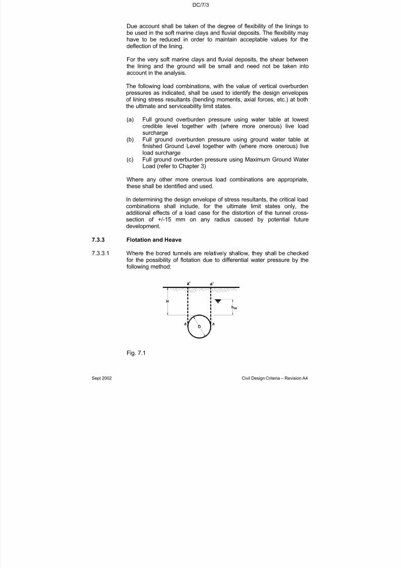
7/18/2019 LTA Civil_standards- Civil Design Criteria
http://slidepdf.com/reader/full/lta-civilstandards-civil-design-criteria 110/345
DC/7/3
Sept 2002 Civil Design Criteria – Revision A4
Due account shall be taken of the degree of flexibility of the linings tobe used in the soft marine clays and fluvial deposits. The flexibility mayhave to be reduced in order to maintain acceptable values for thedeflection of the lining.
For the very soft marine clays and fluvial deposits, the shear betweenthe lining and the ground will be small and need not be taken into
account in the analysis.
The following load combinations, with the value of vertical overburdenpressures as indicated, shall be used to identify the design envelopesof lining stress resultants (bending moments, axial forces, etc.) at boththe ultimate and serviceability limit states.
(a) Full ground overburden pressure using water table at lowestcredible level together with (where more onerous) live loadsurcharge
(b) Full ground overburden pressure using ground water table at
finished Ground Level together with (where more onerous) liveload surcharge
(c) Full ground overburden pressure using Maximum Ground Water Load (refer to Chapter 3)
Where any other more onerous load combinations are appropriate,these shall be identified and used.
In determining the design envelope of stress resultants, the critical loadcombinations shall include, for the ultimate limit states only, theadditional effects of a load case for the distortion of the tunnel cross-
section of +/-15 mm on any radius caused by potential futuredevelopment.
7.3.3 Flotation and Heave
7.3.3.1 Where the bored tunnels are relatively shallow, they shall be checkedfor the possibility of flotation due to differential water pressure by thefollowing method:
Fig. 7.1

7/18/2019 LTA Civil_standards- Civil Design Criteria
http://slidepdf.com/reader/full/lta-civilstandards-civil-design-criteria 111/345
DC/7/4
Sept 2002 Civil Design Criteria – Revision A4
Uplift U = γw π D2 - W4
where γw = specific weight of water W = self weight of tunnel
(See Clause 7.3.3.4 below)D = outside diameter of tunnel
Restraining Force R = γ′ D (hw + D - π D )2 8
+ γb D (H - hw) + 2S (H + D )2
where γ′ = submerged weight of soil
γb = bulk weight of soilS = average shear resistance along a-a'
= cu for cohesive soils
= ½ Ko γ′(H + D/2) tan φ for cohesionless soils
In the above equations for uplift and restraining force, a partial safetyfactor of 2.0 shall be applied to the average shear resistance of theground along the planes of failure, and a partial safety factor of 1.15shall be applied to the average weight of ground above the tunnel, withthe exception of soil type E (Estuarine) to which a partial safety factor of 1.35 shall be applied. The resultant overall factor of safety R/U shallbe not less than 1.2.
7.3.3.2 The relatively shallow bored tunnels in clay shall also be checked for the possibility of heave due to shear failure of the ground at tunnel
invert level by the following method derived from the base heaveanalysis after Bjerrum and Eide (4).
For the general case:
Fig. 7.2
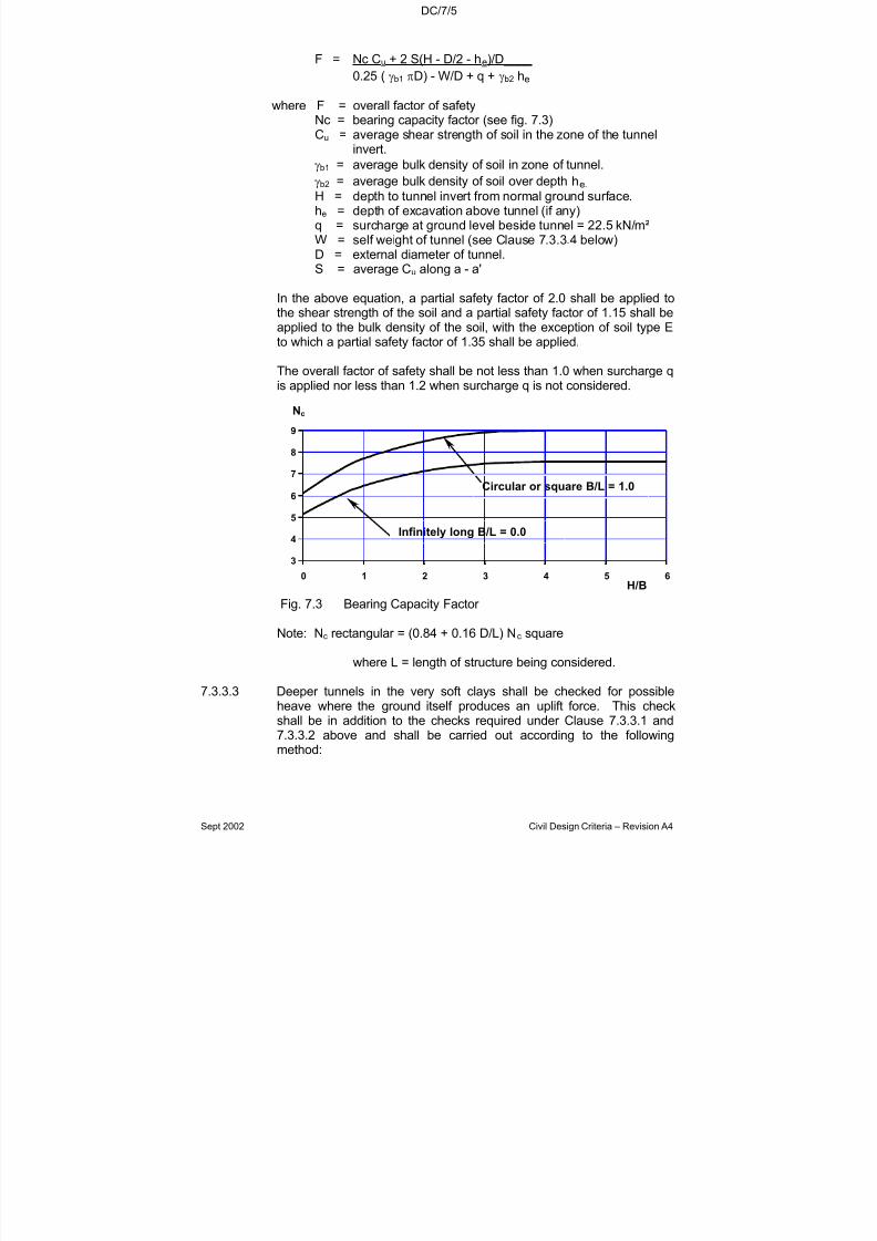
7/18/2019 LTA Civil_standards- Civil Design Criteria
http://slidepdf.com/reader/full/lta-civilstandards-civil-design-criteria 112/345
DC/7/5
Sept 2002 Civil Design Criteria – Revision A4
F = Nc Cu + 2 S(H - D/2 - he)/D____
0.25 ( γb1 πD) - W/D + q + γb2 he
where F = overall factor of safetyNc = bearing capacity factor (see fig. 7.3)Cu = average shear strength of soil in the zone of the tunnel
invert.
γb1 = average bulk density of soil in zone of tunnel.
γb2 = average bulk density of soil over depth he.
H = depth to tunnel invert from normal ground surface.he = depth of excavation above tunnel (if any)q = surcharge at ground level beside tunnel = 22.5 kN/m²W = self weight of tunnel (see Clause 7.3.3.4 below)D = external diameter of tunnel.S = average Cu along a - a'
In the above equation, a partial safety factor of 2.0 shall be applied tothe shear strength of the soil and a partial safety factor of 1.15 shall beapplied to the bulk density of the soil, with the exception of soil type Eto which a partial safety factor of 1.35 shall be applied.
The overall factor of safety shall be not less than 1.0 when surcharge qis applied nor less than 1.2 when surcharge q is not considered.
Fig. 7.3 Bearing Capacity Factor
Note: Nc rectangular = (0.84 + 0.16 D/L) Nc square
where L = length of structure being considered.
7.3.3.3 Deeper tunnels in the very soft clays shall be checked for possibleheave where the ground itself produces an uplift force. This checkshall be in addition to the checks required under Clause 7.3.3.1 and7.3.3.2 above and shall be carried out according to the followingmethod:
3
4
5
6
7
8
9
0 1 2 3 4 5 6
Nc
H/B
Circular or square B/L = 1.0
Infinitely long B/L = 0.0

7/18/2019 LTA Civil_standards- Civil Design Criteria
http://slidepdf.com/reader/full/lta-civilstandards-civil-design-criteria 113/345

7/18/2019 LTA Civil_standards- Civil Design Criteria
http://slidepdf.com/reader/full/lta-civilstandards-civil-design-criteria 114/345
DC/7/7
Sept 2002 Civil Design Criteria – Revision A4
In carrying out the analysis due account of the cyclic nature of theloadings shall be made and stress levels established to ensure that thefatigue life of the structure exceeds the specified design life.
7.3.4.2 An analysis of long term movements of the tunnel shall be carried outto ensure that the tolerances and adjustment limits of the track are notexceeded. These are:
Max. allowable change in grade 1 : 1000
Max. adjustment to track: The lining designer shall refer tothe Particular specification andliaise with the trackworkdesigner to establish the limitof movement incorporated inthe trackwork design, and shallensure that this limit is notexceeded.
Special attention shall be made to the junction between tunnel andstation and at abrupt changes of ground conditions.
The long term movements shall include for all future constructionabove and adjacent to the tunnels shown on the Authority’s Drawings.
7.4 TUNNELS IN ROCK
7.4.1 Definition of Rock
Rock shall include grounds G1 and S1 (see Chapter 5).
7.4.2 Design Method
The Contractor shall use a design method for the analysis of the boredtunnel linings in rock which shall take into account the varying types of material to be encountered.
The Contractor shall consider methods of construction appropriate tothese rock types and shall limit the shape, length, depth and width of
excavations to suit the material encountered.
In the evaluation of the design rock loads for both the primary and finaltunnel linings, due account shall be taken of the proposed method of construction.
7/18/2019 LTA Civil_standards- Civil Design Criteria
http://slidepdf.com/reader/full/lta-civilstandards-civil-design-criteria 115/345
DC/7/8
Sept 2002 Civil Design Criteria – Revision A4
7.5 SEGMENTAL LINING DESIGN
7.5.1 General
7.5.1.1 Segmental bored running tunnel linings shall be in precast concretewith concrete grade at least 60 N/mm². With respect to durability,segmental bored running tunnel linings shall be considered as critical
elements. The chloride diffusion rate of the concrete (without anysurface coating) shall be no more than 1000 Coulomb measured inaccordance with ASTM C1202. Additives can be used in concrete mixto reduce the chloride diffusion rate.
7.5.1.2 Except where a segmental tunnel is used in rock, the design shallconform to Section 7.3.2.
7.5.1.3 The out-of-balance parameters for the distortional loading on the liningsshall take account of the relative speed of reloading of the horizontaland vertical ground pressures and, in the case of shallow tunnels, the
ability of the ground above the tunnel to generate sufficient passiveresistance to maintain stability of the lining.
7.5.1.4 The design of the segmental lining shall satisfy the following distortionalloading coefficients (K), which are the ratio of horizontal soil pressureto vertical pressure prior to lining deformation:
Soil Type K
E, M, F2 0.75B, O, G3, G4, F1 0.5
S4, S4a, S4b 0.4S2, S3, G2 0.3
7.5.1.5 The Contractor shall take into account, inter alia, of the following whenconsidering the design of lining:-
i) The width of segment shall suit the method of construction andshall not be so large that part shoving of the shield becomes anecessity.
ii) The width of segment shall be consistent with the capacity of the
circle bolting arrangements to withstand any shear forcesinduced in linings built with staggered joints.
iii) The stiffness of the lining shall be compatible with the deflectionlimitations in accordance with Clause 7.5.2.
iv) The length of segment shall be chosen with regard to bendingstresses during handling and erection and the long termstresses due to deflection and thrust.
7/18/2019 LTA Civil_standards- Civil Design Criteria
http://slidepdf.com/reader/full/lta-civilstandards-civil-design-criteria 116/345
DC/7/9
Sept 2002 Civil Design Criteria – Revision A4
v) Stresses induced by manufacturing and building tolerancesincluding birdsmouthing of longitudinal joints.
vi) Stresses induced by handling, erection and jacking forward of the tunnelling shield.
vii) Stresses induced by grouting.
viii) All metal fixings/reinforcement/inserts shall be detailed such that
no electrical continuity will exist across the circle joints.
ix) A minimum nominal cover of 40 mm to all reinforcing bars shallbe provided, except only at bolt holes where, provided a plasticsheath is cast in, a reduced cover of 25mm is acceptable.
7.5.1.6 Precast concrete segmental lining shall be designed as short columnsin accordance with SS CP 65.
The following requirements shall also be met:
• At the ultimate limit state, a load factor of 1.4 shall be applied toall ground loads including water pressure, and a load factor of 1.6shall be applied to all live loads including surcharge.
• At the serviceability limit state, the calculated maximum crack-width shall not exceed 0.2 mm. For this check the imposed loadshall include the surcharge load in Chapter 3 (except where thisgives a beneficial effect). The design checks for crack-width shallcomply with SS CP 73.
• In respect of containment of compression reinforcement, the
requirements of SS CP 65 Clauses 3.12.7.1 and 3.12.7.2 for columns shall apply. However as an alternative where mesh isused to enhance the behaviour under fire, the number of restraining link bars may be reduced by 50%, but to a spacingalong the bars being restrained of not more than 300mm.
• The design of the segments shall allow for all temporary loadsduring handling and erection. The design assumptions shall bereviewed once these loads have been finalised, and the segmentdesign amended as necessary.
7.5.1.7 With regard to Clause 7.5.1.5(v) above, the Contractor's attention is
drawn to the inter-relationship between the tolerances on plane of thelining, steps between the edges of segments and the ability of thesegmental lining to carry shield jacking loads without cracking. TheContractor shall analyse the loadings in the segments arising from theshield jacks and establish suitable tolerances on these parameters toensure that the segments remain uncracked.

7/18/2019 LTA Civil_standards- Civil Design Criteria
http://slidepdf.com/reader/full/lta-civilstandards-civil-design-criteria 117/345
DC/7/10
Sept 2002 Civil Design Criteria – Revision A4
7.5.1.8 The Contractor shall allow in his design for eccentricities of thrustbetween adjacent segments arising from the following factors:-
(a) building errors such as:
• lack of circularity.
• steps between segments.
• out of plane of circumferential joint.
- see M & W Specification for allowable tolerances.
(b) Casting inaccuracies- see M & W specification for allowable tolerances.
(c) Rotation under load
The Contractor shall calculate the rotation produced at each joint between segments as the lining deflects under load. Theresultant eccentricity in the point of contact between segmentsfrom all these factors shall be calculated from the joint geometry.
7.5.1.9 Where staggered longitudinal joints are used no increase in liningflexibility will be permitted in the design due to longitudinal jointrotations, except that when checking the load combination of additionaldistortional movement of +/-15mm on any radius, the reduction in liningstiffness recommended by AM Muir Wood(1) may be adopted.
7.5.1.10 Permissible tensile stresses in concrete shall be determined in a similar manner to compression stresses.
7.5.2 Deflections
The maximum deflection due to the design load shall not exceed 25mm on radius. The degree of flexibility of the lining shall be designedto ensure that this limit is not exceeded.
If an arrangement of staggered longitudinal joints is adopted, theincreased stiffness of the lining may induce shear across thecircumferential flanges. The effect of this, in particular the shear on thecircle joint connections, shall be investigated.
7.5.3 Waterproofing
A high standard of waterproofing of bored tunnel linings will berequired. Groundwater leakage rates shall not exceed a general valueof 2 millilitres/m2 of lining area/hour. For any 10 metre length of tunnelthe leakage rate shall not exceed 5 millilitres/m²/h.
7/18/2019 LTA Civil_standards- Civil Design Criteria
http://slidepdf.com/reader/full/lta-civilstandards-civil-design-criteria 118/345
DC/7/11
Sept 2002 Civil Design Criteria – Revision A4
The design shall incorporate suitable methods of waterproofing. Thisshall include the use of the following throughout the segmental tunnellining:
a) A water sealing system consisting of either an elastomericgasket and a separate hydrophilic sealing strip or a singlecomposite gasket consisting of an elastomeric carrier and
hydrophilic facing material. The system shall be designed, testedand installed to the acceptance of the Engineer.
b) Unless otherwise accepted by the Engineer, the elastomericmaterial shall be an EPDM (Ethylene Propylene DieneMonomer) formulated to provide good retention of elasticity and
low stress relaxation properties.
c) The outer (convex) surface of all segments that contain steel bar reinforcement, together with all side faces, gasket recesses,caulking grooves and insides of bolt holes and grout holes shall
be painted with a solvent free or (water based) emulsion epoxycoating.
d) Grummets on all bolts if either the sealing strip or gasket is infront of the bolt hole; otherwise, provision shall be made for grummets.
e) Provision for caulking around all edges of segments.
A full specification for the above is given in the M & W Specifications.
The selection of the materials to be used shall be based on life cyclecost assessment of feasible options in accordance with Clause 1.6.4.
The design shall make provision to prevent the built up of water pressure beneath the in-fill base concrete or beneath the track slabconcrete. To achieve this, leakage paths shall be created at each jointin the tunnel lining and any seepage directed to the drainage channel.
Notwithstanding the above limits on ground water leakage rates, theContractor shall ensure that no loss of ground occurs through any partof the completed structure.
In order to minimise surface settlements due to consolidation in the softgrounds, the specified degree of water tightness shall be achievedwithin 30 m of the tunnel face. In all other ground conditions, thespecified degree of watertightness shall be achieved by the TunnelBasic Structure Completion Date.

7/18/2019 LTA Civil_standards- Civil Design Criteria
http://slidepdf.com/reader/full/lta-civilstandards-civil-design-criteria 119/345
DC/7/12
Sept 2002 Civil Design Criteria – Revision A4
7.5.4 Fixings
Every available location on each tunnel segment shall be marked toindicate where drilling is permitted for the fixing of cable brackets andother attachments.
The marking shall take the form of indented areas, dimples or the like
on the surface of the segment. The indentations shall not exceed 6mmin depth.
For the purpose of defining the location of the demarcated areas, itshall be assumed that holes to suit 16 mm diameter expanding bolts or sockets will be used for the fixings and that the clear distance betweenthe side of the hole and any reinforcement shall be not less than 40 mmafter making full allowance for inaccuracies in the position of thereinforcement.No fixings shall be installed outside the demarcated areas without prior acceptance from the Engineer.
Locations of brackets and other attachments shall be selected suchthat tunnel bolts and grout plugs are not obstructed should anysubsequent tightening or replacement of such bolts and plugs berequired. Furthermore, obscuring the tunnel joints shall be avoided asfar as practicable.
7.5.5 Taper Rings
The Contractor shall design suitable taper ring linings in order tonegotiate the alignment curvature and to correct for line and level
during construction with the minimum use of circumferential jointpackers consistent with attaining the required degree of watertightnessof the tunnels.
7.5.6 Bolt Pockets
Bolt pockets in which water may possibly accumulate shall be filled withgrade 30 concrete.
7.6 TEMPORARY TUNNEL LININGS
7.6.1 Types of Lining
A system of temporary support may be adopted in all grounds exceptE, M, F1 and F2.
The system of primary support shall be some combination of shotcrete, rock bolts, steel arch ribs and lagging or such other systemas the Contractor may propose subject to the acceptance of theEngineer.

7/18/2019 LTA Civil_standards- Civil Design Criteria
http://slidepdf.com/reader/full/lta-civilstandards-civil-design-criteria 120/345
DC/7/13
Sept 2002 Civil Design Criteria – Revision A4
7.6.2 Sprayed Concrete Lining (SCL)
Sprayed concrete lining should not be carried out where the stand-uptime for the excavation is inadequate. As a guide stand-up time shouldbe more than 90 minutes for a face advance of 1 metre.
The design and construction methodology shall address the following :
a) length of advanceb) whether advance should be partial face or full facec) inclination of faced) speed of ring closuree) face supportf) adjacent activities, such as excavations and ground treatment.
The design of the primary lining shall take into account the following:
a) the ground conditions including :- soil stratigraphy;- the groundwater regime;- soil strength, stiffness and small-strain characteristics;- swelling and creep characteristics;- Poisson’s ratio.
b) the material properties including :- development of strength;- stiffness (modulus) appropriate to the age of the concrete
and the excavation stage;- creep and shrinkage especially in first two weeks after
placing.
c) the ground-lining interaction including non-linear and timedependent behaviour.
d) the speed of loading, both horizontally and vertically including :- the impact of any adjacent construction or ground
treatment;- water pressure relief (or lack of relief).
The minimum thickness of SCL in soft ground shall be:
• 150mm for tunnel diameter less than 4m.
• 200mm for tunnel diameter less than 5m.
• 250mm for tunnel diameter 5m or greater.
In soft ground full circle ribs shall be used at spacing equal to the lengthof advance.
7/18/2019 LTA Civil_standards- Civil Design Criteria
http://slidepdf.com/reader/full/lta-civilstandards-civil-design-criteria 121/345
DC/7/14
Sept 2002 Civil Design Criteria – Revision A4
The design shall be reviewed and modified during and after construction as a result of comprehensive monitoring of the following :
• the behaviour of the ground at the tunnel face in comparison withthe design assumptions.
• surface settlements.
• lining deformations.
• measurements of ground loadings and displacements.
Appropriate contingency plans shall be prepared and implemented tomodify the design and construction should the behaviour of the groundor the lining be shown by the monitoring to be outside the predictionlimits.
7.6.3 Ribs and Lagging
The design of a primary support system using ribs and lagging in rock
shall be in accordance with a recognised method such as loadingassessed in accordance with Terzaghi (6) and a graphical analysis of the steel arch rib after Procter and White (7).
The Contractor shall take into account, inter alia, the following in thedesign of the primary support system:
(a) Axial and bending stresses in the steel arch ribs induced by therock loads.
(b) Lateral stability and bracing of the steel arch ribs.(c) The method of forming the steel arch ribs and the resultant
properties of the steel.(d) Amount of preload to be applied to steel arch ribs and method
of supplying this load.(e) Method of blocking and spacing of blocking points.(f) Bearing capacity of the rock at blocking points and, in the case
of horseshoe-shaped cross section, under the footplates.(g) The stand up time of the unsupported part of the excavation.(h) The method of lagging between ribs to prevent ravelling and/or
softening of the ground.(i) The ground water regime and permeability of the ground.
The allowable stresses in the steel arch ribs shall be in accordancewith BS 449. The design shall not permit any overstress.

7/18/2019 LTA Civil_standards- Civil Design Criteria
http://slidepdf.com/reader/full/lta-civilstandards-civil-design-criteria 122/345
DC/7/15
Sept 2002 Civil Design Criteria – Revision A4
7.7 IN-SITU TUNNEL LINING
7.7.1 General
In-situ tunnel lining shall be in concrete of minimum grade 45containing silica fume as specified in the Material and WorkmanshipSpecification. The minimum nominal cover for durability shall be 40mm.
7.7.2 Analysis
The analysis of the stresses induced in the final lining shall takeaccount of the following:-
(a) The long term horizontal and vertical ground loads.(b) The sequence of construction.(c) The proximity of other tunnels and structures.(d) The distortion of the cavity.(e) The ground water loading.
The design of the final lining shall ignore any possible contribution tosupport of the imposed loads by the primary support system.
The following requirements shall be met:
• At the ultimate limit state, a load factor of 1.4 shall be applied to allground loads including water pressure, and a load factor of 1.6 shallbe applied to all live loads including surcharge.
• At the serviceability limit state, the calculated maximum crack-widthshall not exceed 0.2 mm. For this check the imposed load shall
include the surcharge load in chapter 3 (except where this gives abeneficial effect). The design checks for crack-width shall complywith SS CP 73.
• In respect of containment of compression reinforcement, therequirements of SS CP 65 clauses 3.12.7.1 and 3.12.7.2 for columnsshall apply. However as an alternative where mesh is used toenhance the behaviour under fire, the number of restraining link barsmay be reduced by 50%, but to a spacing along the bars beingrestrained of not more than 300mm.
7.7.3 Waterproofing
Leakage rates shall not exceed the values quoted in Clause 7.5.3above. A waterproofing membrane system is to be provided betweenthe temporary lining and permanent in-situ concrete lining except atcross passageways. The membrane is to be compartmentalised andfully welded to cover the full tunnel extrados.
The watertightness membrane system, grade of concrete, thickness of lining, method of placement, treatment of construction joints andarrangements for back-grouting shall be chosen such that adequatewaterproofing can be achieved.
7/18/2019 LTA Civil_standards- Civil Design Criteria
http://slidepdf.com/reader/full/lta-civilstandards-civil-design-criteria 123/345
DC/7/16
Sept 2002 Civil Design Criteria – Revision A4
At cross passageways and sumps, an integral waterproofing systemcomprising approved waterproofing admixture and provisions for back-grouting shall be used for waterproofing the permanent insitu concretelining. The type of admixture, grade of concrete, thickness of lining,method of placement, treatment of construction joints andarrangements for re-injectable back-grouting shall be chosen such that
adequate waterproofing can be achieved.
7.7.4 Fixings
Drilled-in blind holes shall be provided where required around thetunnel lining for the fixing of brackets and equipment of electrical/mechanical nature.
7.8 CROSS PASSAGEWAYS BETWEEN RAILWAY RUNNING
TUNNELS
7.8.1 Location
Cross passageways between bored running tunnels shall be located inaccordance with the requirements of the Standard for Fire Safety inRapid Transit Systems, Singapore Civil Defence & Land Transport
Authority
Track cross-overs shall not be considered as cross-passages.
Wherever possible, cross passageways shall be located to avoid
critical sections of the alignment where their construction could have anadverse effect on adjacent structures.
7.8.2 Dimensions and Layout
Throughout the length of the cross passageway, a minimum headroomof 2.2m shall be maintained over a clear width of 1.2m except at thedoor where the requirements in the Standard for Fire Safety in RapidTransit Systems, Singapore Civil Defence & Land Transport Authorityshall be complied with.
The level on the cross passageway floor shall be determined, on acase by case basis, in relation to the cant of the track. Generally thecross passageway level shall be three steps above the adjoiningtrackbed level as determined by the trackwork designer.
The cross passageway floor shall drain into the running tunnel drainagesystem, unless the cross passageway occurs at the low point of thealignment in which case a drainage sump may be located within thecross passageway.

7/18/2019 LTA Civil_standards- Civil Design Criteria
http://slidepdf.com/reader/full/lta-civilstandards-civil-design-criteria 124/345
DC/7/17
Sept 2002 Civil Design Criteria – Revision A4
Opening in cross passageways shall be protected with a fire door assembly having a fire resistance of not less than 2 hours with a self closing device in accordance with Section 2.9 of Standard for FireSafety in Rapid Transit Systems.
7.8.3 Design
In soft ground, the tunnel lining shall be designed generally inaccordance with the requirements of Clause 7.5 or 7.7 above asappropriate with the following exceptions:-
a) The maximum allowable deflection on radius shall be 15 mm.b) Taper rings will not be required.
The junctions with the running tunnels shall be steel framed andencased with in-situ concrete or framed with reinforced concrete. The
junctions shall be designed to fully support the running tunnel linings atthe openings together with the ground and ground water loads on the
junction itself.
Where openings are to be formed in running tunnels having segmentalconcrete linings, the Contractor shall provide temporary internalsupports to the running tunnel lining. These supports shall adequatelyrestrain the lining such that on completion of the cross passagewayand removal of the temporary supports the total deflection of the liningdoes not exceed the requirements of Clause 7.5.2.
7.9 SUMPS IN RUNNING TUNNELS
Refer to Chapter 11 for design requirements for pump sumps inrunning tunnels.
7.10 EMERGENCY ESCAPE SHAFTS
7.10.1 Location
Locations of emergency escape shaft shall be in accordance withSection 2.9 of the Standard for Fire Safety in Rapid Transit Systems
issued by the Singapore Civil Defence Force & Land Transport Authority.
7.10.2 Dimensions and Layout
The layout of the shaft shall conform to the Standard for Fire Safety inRapid Transit Systems issued by the Singapore Civil Defence Force &Land Transport Authority.
The floor of the shaft shall be level with the walkway level in the tunnel.
7/18/2019 LTA Civil_standards- Civil Design Criteria
http://slidepdf.com/reader/full/lta-civilstandards-civil-design-criteria 125/345
DC/7/18
Sept 2002 Civil Design Criteria – Revision A4
7.10.3 Shaft Design
Shaft linings shall be designed generally in accordance with Clause7.3.2, 7.5 and 7.7 with the exception that:
a) There is not distortional loading unless ground conditions areexceptional.
b) The thrust in the lining shall be based on full hydrostatic and K0
earth pressures.
The junctions with the running tunnels shall be steel framed andencased with in-situ concrete. The junctions shall be designed to fullysupport the running tunnel linings and shaft linings at the openingstogether with the ground and ground water loads on the junction itself.
While the openings into the running tunnel and the shaft are beingformed, temporary internal supports to the running tunnel lining. and
shaft lining shall be provided. These supports shall adequately restrainthe linings such that on completion of the junction and removal of thetemporary supports the total deflection of the linings do not exceed therequirements of Clause 7.5.2.
7.11 TUNNEL WALKWAY IN RAILWAY TUNNELS
7.11.1 Arrangement
The location and width of the tunnel walkway are shown on Authority’s
drawings.
7.11.2 Details of Walkway
The walkway shall fall 15 mm towards the track.
The handrail shall project no less than 75 mm from the tunnel wall andbe clear of any tunnel service to enable easy use. The handrail shallnot project into the walkway envelope.
The walkway shall be ramped down to cross-passage floor level at
each cross passageway and ramped down to rail level at switch andcrossing areas.
7.12 FIRST STAGE CONCRETE
7.12.1 The first stage concrete is defined as the concrete between the tunnellining and the track concrete placed by the trackwork contractor. Thefirst stage concrete, or concrete on which the second stage is cast,should have an exposed aggregate finish.

7/18/2019 LTA Civil_standards- Civil Design Criteria
http://slidepdf.com/reader/full/lta-civilstandards-civil-design-criteria 126/345
DC/7/19
Sept 2002 Civil Design Criteria – Revision A4
7.12.2 The minimum concrete grade shall be grade C30 having acharacteristic cube strength at 28 days of 30 N/mm
2.
7/18/2019 LTA Civil_standards- Civil Design Criteria
http://slidepdf.com/reader/full/lta-civilstandards-civil-design-criteria 127/345
DC/7/20
Sept 2002 Civil Design Criteria – Revision A4
References
1. Muir Wood AM. The circular tunnel in elastic ground.Geotechnique 25 No.1, 1975.
2. Curtis DJ. Discussion on 3 above.
Geotechnique 26 No.1, 1976.
3. Duddeck H and Structural design models for tunnels.Erdmann J. Tunnelling 1982, pp 83-91
4. Bjerrum L. and Stability of strutted excavations in clay.Eide O. Geotechnique 6, 1956.
5. Meyerhoff GG. The ultimate bearing capacity of foundations.Geotechnique Vol.2 No.41, 1951.
6. Peck RB. Deep excavation and tunnelling in soft ground.State of the Art Report. 7th InternationalConference on Soil Mechanics and FoundationEngineering, Mexico City 1969.
7. Terzaghi K. Rock tunnelling with steel supports, Section 1.Commercial Shearing and Stamping Co. 1946.
8. Proctor and White. Rock tunnelling with steel supports.Commercial Shearing and Stamping Co.1946.

7/18/2019 LTA Civil_standards- Civil Design Criteria
http://slidepdf.com/reader/full/lta-civilstandards-civil-design-criteria 128/345
DC/8/1
Sept 2002 Civil Design Criteria – Revision A4
CHAPTER 8
UNDERGROUND STRUCTURES
8.1 GENERAL
8.1.1 Scope
Design requirements for depressed or underground structuresconstructed by cut-and-cover methods and associated temporaryworks are covered in this Chapter.
Underground drainage culverts and canals beneath roadways andrailways shall be designed using this Chapter. However, for thesestructures, the waterproofing and 0.2mm crack width requirements donot apply.
8.1.2 General Principles
The following general principles shall be followed:
(a) The Permanent Works shall be of reinforced concreteconstruction, unless otherwise accepted by the Engineer.Prestressed concrete will in general not be acceptable.
(b) The design, and selection of construction method, of cut andcover structures shall take into account at least the following:
(i) The geology.
(ii) The hydrogeology and strata permeabilities in the vicinityof the excavation.
(iii) The degree of lateral movement and settlement whichwould be expected. In this context the location of theworks in relation to existing structures shall beconsidered.
(iv) The depth of construction.
(v) Any particular difficulties that special plant might face withrespect to access, clearances and working space.
(vi) The noise levels and environmental pollution produced.
(vii) Control over heave and instability of the base of theexcavation, and long term settlement and heave.

7/18/2019 LTA Civil_standards- Civil Design Criteria
http://slidepdf.com/reader/full/lta-civilstandards-civil-design-criteria 129/345
DC/8/2
Sept 2002 Civil Design Criteria – Revision A4
(viii) The methods by which the completed structure shall besecured against flotation.
(ix) The method for waterproofing the completed structure.
(c) In the case of railways no movement joints are allowed acrossthe track. For vehicular underpasses and depressed
carriageways the number of movement joints shall be minimisedas far as possible. The underground works shall be designed asfar as possible to be structurally continuous and the groundpressure distribution, long term ground / structure interaction,total and differential settlement shall be considered accordingly.Where it is necessary to use movement joints they shall be heavyduty with positive reinforcement connections to the structure.Where applicable, they shall be able to resist the uplift pressure.They shall be designed to be easily maintained and replaceable.Irrespective of whether or not the movement joints are locatedbeneath a roadway, the vertical deflection of any unit (or section)
of the structure under the application of primary live loads at theserviceability limit state must be less than 0.015H, where H is theheight of cover above the structure.
(d) The underground structure shall be completely waterproofed asdescribed in this Chapter. However, the structure shall becapable of withstanding aggressive soil and water conditions thatmay be present without having to rely on the waterproofing.
(e) The method and sequence of construction, including installationand removal of Temporary Works, shall be considered in the
design and be clearly defined in the design drawings. Possibleimperfections in fabrication and erection shall be considered inthe design and the structurally acceptable margins of toleranceshall be clearly specified for critical members and operations.
Any constraints that the design may place on the constructionsequence shall be identified and clearly specified in the designdrawings. The design of structures in which the permanent wallsand slabs are also used to carry temporary construction loadsmust be fully compatible with the method of construction to beadopted.
(f) Requirements for ground instrumentation, monitoring andcontingency plans for modification of construction methods shallbe evaluated having proper regard to the uncertainties inherent inthe design. These requirements shall be fully described in thedrawings.
(g) The design of temporary / permanent walls, and of dewateringmethods within both permanent and temporary walls shall, as far as possible, avoid lowering of the water table outside the Worksand shall ensure sufficient cut-off to minimise the reduction inpiezometric pressure in the adjacent soils.
7/18/2019 LTA Civil_standards- Civil Design Criteria
http://slidepdf.com/reader/full/lta-civilstandards-civil-design-criteria 130/345
DC/8/3
Sept 2002 Civil Design Criteria – Revision A4
(h) Structures shall be designed in such a manner that settlementand heave during all stages of construction and throughout theservice life of the structure is kept to a minimum.
(i) All underground structures below roads shall have a groundcover of 2 metres minimum, measured from top of waterproofing
to the lowest point on the carriageway unless shown otherwiseon the Authority’s Drawings.
(j) Unless agree otherwise in writing by the Authority, a water retaining structure shall be provided at each UndergroundStructure entry and exit between the face of the UndergroundStructure portal and where the top of the bottom slab, across itsfull width, is wholly above existing ground level or such higher level as the Authority or other authorities may require. Atransition slab shall be provided at the end of each such water-retaining structures as specified in Chapter 6.
8.1.3 General Requirements for Trainways in Cut-and-Cover Tunnels
and Stations
8.1.3.1 Size of Tunnel
With the exception of cells containing sidings per Clause 8.1.3.6, thesize of each cell of a cut-and-cover tunnel shall accommodate thevarious items listed in Clause 7.2.1. Items (f) to (i) can beaccommodated in spaces 300mm wide on the walkway side of the
tunnel and 350mm wide on the opposite side of the tunnel as shown onthe Authority’s Drawings.
8.1.3.2 Cross Passageways
Cross passageways between two independent single-bound cut-and-cover tunnels shall conform to Clauses 7.8.1 and 7.8.2. The door shall be of sliding type if necessary.
8.1.3.3 Drainage Sumps
The requirements of Clause 11.2.2 shall apply for sumps within thelengths of cut-and-cover tunnel
8.1.3.4 Ventilation
In track crossover areas the tunnel ventilation regime may bemaintained by the use of jet fans mounted in the roof of the cut-and-cover tunnel. Vertical enlargements in the structure shall be providedfor these fans. The size and extent of the structural enlargement andclearance requirements to any overhead conductor envelope shall bedetermined in co-ordination with the relevant System-wide Contractors.
7/18/2019 LTA Civil_standards- Civil Design Criteria
http://slidepdf.com/reader/full/lta-civilstandards-civil-design-criteria 131/345
DC/8/4
Sept 2002 Civil Design Criteria – Revision A4
8.1.3.5 Separation of Trainways
With the exception of tracks within the Depot boundaries, all trainwayswhether for mainline tracks, centre sidings, test tracks or any other purpose, shall be separated from adjacent trainways or other operational areas (for example plantrooms in stations) by continuousreinforced concrete dividing walls, which extend as far as possible
consistent with provision of openings for crossovers, cross passages,or other operational requirements, to the acceptance of the Engineer.The precise setting out of the dividing walls shall be co-ordinated withthe System-wide Contractors, and agreed with the Engineer.
8.1.3.6 Cells Containing Sidings
The minimum internal width of cells for sidings shall accommodate:
(a) The Static Load Gauge, increased as necessary for VehicleThrow
(b) 600 mm minimum clearance between the Static Load Gauge(increased for Vehicle Throw) and service zones, toaccommodate access at track level to a stationary train.
(c) 350 mm wide service zones on each side.
8.1.3.7 First Stage Concrete
The first stage concrete is defined as the concrete needed to fill thegap, if any, between the top of the structural slab/tunnel lining and the
underside of the track concrete placed by the trackwork contractor. Itwould therefore not be necessary to provide a separate layer of firststage concrete if the top of structural slab matches the level of theunderside of the second stage (track slab) concrete.
The minimum concrete grade for the first stage concrete shall be gradeC30. The minimum thickness shall be 300mm.
8.1.3.8 Concrete Finish at interfaces between Trainway Structure, First Stageand Second Stage Concrete
The concrete finish in all trainways at the interface between thetrainway structure and the first stage concrete or the second stageconcrete (if no first stage), and between the first and second stageconcrete (where both are used) shall be an exposed aggregate finish.This requirement shall be shown on the design drawings.
7/18/2019 LTA Civil_standards- Civil Design Criteria
http://slidepdf.com/reader/full/lta-civilstandards-civil-design-criteria 132/345
DC/8/5
Sept 2002 Civil Design Criteria – Revision A4
8.1.4 General Requirements for Vehicular Underpasses and DepressedCarriageways
8.1.4.1 A minimum headroom clearance of 5.4 metres above all roadways shallbe maintained across the full width of each carriageway. This applies toboth permanent and temporary structures.
8.1.4.2 The underpass shall be designed to allow for positioning and housing of electrical lighting fixtures, mechanical ventilation system if any andopenings for cabling works.
8.2 DESIGN APPROACH
8.2.1 The design of underground railway structures (whose function isprimarily to serve railways and their passengers) shall comply with SSCP 65, SS CP 73, BS 8002, BS 8004, other relevant codes and theadditional requirements herein.
8.2.2 The design of underground roadway structures (whose function isprimarily to serve roadways) and other underground structures shall bedesigned to BS 5400 (Refer Design Criteria Clause 1.2.2), BS 8002,BS 8004, SS CP 73, other relevant codes, United Kingdom Highways
Agency Departmental Standards (Refer Design Criteria Clause 1.2.3)and the additional requirements herein.
8.3 ULTIMATE LIMIT STATE
8.3.1 Structural Stability
For each major structure (tunnels, stations, subways, underpassesetc) there shall be a clear statement as to how the stability of thestructures under the design loads is to be achieved. This statementshall address, where applicable, loads from future developments or from the construction of future developments.
Underground Structures shall be checked for stability against flotationin accordance with Clauses 1.3.4 and 8.14. They shall also bechecked against failure due to base heave in accordance with Clause
8.15.
Structural stability of earth retaining structures against overturning andsliding shall be assessed in accordance with Chapter 6.
8.3.2 Robustness
Refer to Chapter 3 of the Design Criteria for the effects of impact loadsand the provision of ties.

7/18/2019 LTA Civil_standards- Civil Design Criteria
http://slidepdf.com/reader/full/lta-civilstandards-civil-design-criteria 133/345
DC/8/6
Sept 2002 Civil Design Criteria – Revision A4
8.4 SERVICEABILITY LIMIT STATE
8.4.1 Settlement
Refer to Chapter 6.
8.4.2 Cracking
All members shall comply with the requirements of the relevant Codesin respect of limitations on crack width. The maximum crack widthunder any conditions shall not exceed 0.3 mm, or such other smaller value as required by the Codes. For members designed to BS 5400 to“very severe” exposure conditions, the design crack width may betaken as 0.2 mm, unless the members under consideration areadjacent to seawater when the more stringent limitation in BS 5400 of 0.15 mm would apply.
In addition, in order to promote water-tightness, those members
exposed to earth and/or ground water and forming the hull of underground structures (i.e. roof, walls, base slabs etc.), shall bedesigned such that the calculated maximum crack width on bothexternal and internal faces due to early age thermal cracking or flexureand/or tension arising from applied external service loads does notexceed 0.2mm on a plane at a distance of 40mm from the outermostreinforcement, irrespective of whether any additional protection (for example a waterproofing membrane) is provided. Where the loadcombinations for the purposes of checking this crack width includesurcharge loading, the value of such unfactored live load surchargeshall be taken as 17 kN/m2.
For embedded concrete walls, the load effects (bending moments etc,)for which this crack width of 0.2mm is checked shall include thosewhich are “locked-in” at construction. Where the embedded wall isdesigned and detailed to be structurally composite with an inner wall,the crack width at the interface with the inner wall may be 0.3mm. For load effects during construction which are not “locked-in”, the crackwidth shall not exceed 0.3 mm.
Provision shall be made to ensure that calculated crack widths on anyface of such members due to early thermal cracking do not exceed
0.2mm.
The widths of cracks caused by applied external service loads need notbe added to those caused by early-age thermal cracking andshrinkage.
The width of the cracks referred to above shall be calculated using theformulae in SS CP 73.

7/18/2019 LTA Civil_standards- Civil Design Criteria
http://slidepdf.com/reader/full/lta-civilstandards-civil-design-criteria 134/345
DC/8/7
Sept 2002 Civil Design Criteria – Revision A4
8.5 DURABILITY
The elements of underground structures which form the PermanentWorks in contact with earth and / or groundwater shall be consideredcritical elements with respect to durability. Selection of water bars and
joint sealants shall be based on a life cycle cost assessment (seeChapter 1) of the feasible options. Durability provisions in the following
clauses are minimum requirements.
8.5.1 Exposure Conditions
The following minimum conditions of exposure per SS CP 65: Part 1Table 3.2 for underground structures designed to SS CP 65 and Table13 of BS 5400: Part 4 for underground structures designed to BS 5400shall be allowed for in the designs:
(a) The external surface of concrete forming the hull of underground
structures (i.e. roof, walls, base slabs): very severe
(b) Where an in-situ inner wall is cast against an embedded wall(diaphragm wall, secant pile wall or contiguous bored pile wall),both the inner face of the embedded wall and the outer face of inner wall: severe
(c) The internal surface of concrete forming the hull of undergroundstructures, and the face of all members exposed to trainways (in
both cut and cover tunnels and in stations) or roadways: severe(d) Internal members of underground structures other than above:
moderate
8.5.2 Minimum Cover
Notwithstanding the cover derived from the exposure conditions givenin Clause 8.5.1 above, the nominal cover to the outermostreinforcement shall be not less than 40mm for the following locations:
(a) external and internal faces of members forming the external hullof underground structures
(b) both faces of in-situ inner walls cast against the walls of externalhull members
(c) the faces of members exposed to trainways or roadways
8.5.3 Cement and Water Content
Notwithstanding the cement and water content values derived from SSCP 65 table 3.4 the following maximum and minimum values shall beadhered to.
The minimum cement content of members forming the hull of underground structures and members exposed to trainways or roadways shall be not less than 350kg/m3.
7/18/2019 LTA Civil_standards- Civil Design Criteria
http://slidepdf.com/reader/full/lta-civilstandards-civil-design-criteria 135/345
DC/8/8
Sept 2002 Civil Design Criteria – Revision A4
The minimum cement content for other members shall otherwise be notless than 325kg/m
3.
The maximum cement content shall be limited by the need for temperature control when early thermal and drying shrinkage arepotential cause of cracking. In the case of OPC, the maximum cementcontent shall not exceed 400kg/m3.
The maximum free water cement ratio shall not exceed 0.45.
The above represent minimum and maximum typical requirements.The design shall allow for more onerous exposure conditions and/or aggressive chemical and physical conditions where such conditions arelikely to be present.
8.5.4 Shrinkage and Thermal Cracking
Adequate consideration shall be given to the risk of early-age thermal
cracking and shrinkage effects. The designer shall ensure that anyrequirements considered appropriate such as cement chemistry andcuring methods are properly addressed in his review of the Materialsand Workmanship Specification.
Crack widths due to early-age thermal cracking and shrinkage shall becalculated using SS CP 73. In the case of early-age thermal cracking,reference shall also be made to CIRIA Report 91 [1] and BD 28/87, for structures designed to SS CP 65 and BS 5400, respectively. However the beneficial effects of using cement replacement materials and other techniques such as internal cooling to control the heat of hydration may
be taken into account provided that suitable evidence is presented to justify the magnitude of these effects.
8.6 FIRE RESISTANCE
8.6.1 With the exception only of non-loadbearing separation walls, all other elements of underground structures shall be designed and detailed for a 4 hour fire resistance, unless specified otherwise for railways in theLand Transport Authority Standard for Fire Safety in Rapid TransitSystems.
8.6.2 Attention is drawn to the further information on fire in SS CP 65 Part 2.The structures shall be detailed to ensure that the required fireresistance is met, and in such a way as to avoid spalling, and, as far aspossible, also to avoid the need for the use of mesh, whilst complyingwith the code. When it is necessary to use mesh, the minimum sizeshall be A252 to BS 4483.
8.6.3 In the case of non-loadbearing separation walls, their fire resistanceshall be determined by other requirements, such as firecompartmentation etc.

7/18/2019 LTA Civil_standards- Civil Design Criteria
http://slidepdf.com/reader/full/lta-civilstandards-civil-design-criteria 136/345
DC/8/9
Sept 2002 Civil Design Criteria – Revision A4
8.7 INSPECTION OF CONSTRUCTION
Attention is drawn to Clause 2.3 of SS CP 65: Part 1. Constructiontolerances shall meet the requirements of the relevant British Standardor those given in the Materials and Workmanship Specifications,whichever is the more onerous.
8.8 LOADS
The general loading requirements are given in Chapter 3, except thatwhen checking crack width, the unfactored live load surcharge inClause 8.4.2 may be used (and not the higher surcharge specified inChapter 3).
Additional loading requirements for Underground Structures are givenbelow.
8.8.1 Load Factors for Earth and Water Pressure
8.8.1.1 Requirements for Underground Structures designed to SS CP 65:
(a) The design shall meet the requirements of SS CP 65: Part 1.
(b) In addition, in load cases where the critical stresses in thestructure would be produced by maximum earth and water pressure acting in one direction (e.g. on roof slab) incombination with minimum earth and water pressure acting inthe other, (e.g. on side walls) and where both water pressures
are derived from the same ground water level then the earth andwater load factors shall be taken as 1.4 and 1.2 respectively toobtain the maximum and 1.0 and 1.0 respectively to obtain theminimum loads.
8.8.1.2 Requirements for Underground Structures designed to BS 5400:
(a) Partial Safety Factors for Loads
The partial safety factors for loads shall be in accordance withthe requirements of BD 37/88, except where modified as follows:
LOAD SLSγfl
ULSγfl
COMBINATIONS
SuperimposedDead Load
1.0 1.2 All combinations
Hydrostatic Pressure 1.1 1.1 All combinations
SLS: Serviceability Limit StateULS: Ultimate Limit State
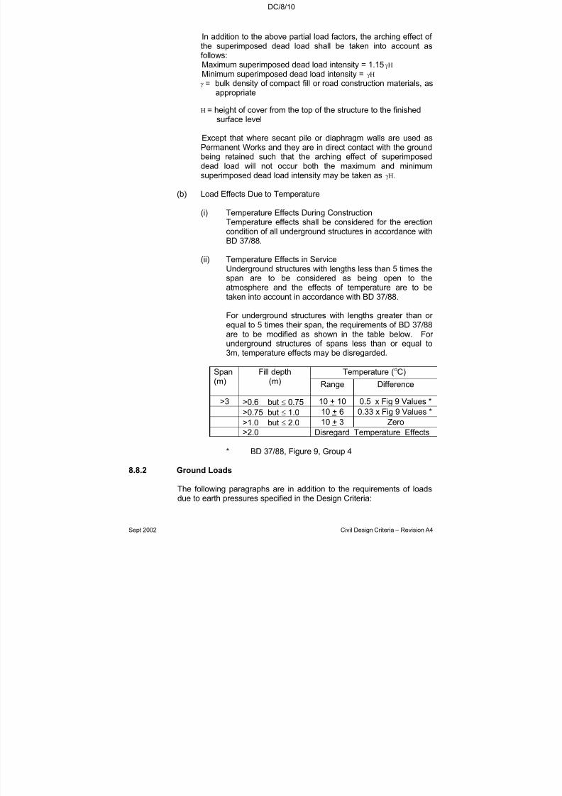
7/18/2019 LTA Civil_standards- Civil Design Criteria
http://slidepdf.com/reader/full/lta-civilstandards-civil-design-criteria 137/345
DC/8/10
Sept 2002 Civil Design Criteria – Revision A4
In addition to the above partial load factors, the arching effect of the superimposed dead load shall be taken into account asfollows:Maximum superimposed dead load intensity = 1.15γHMinimum superimposed dead load intensity = γHγ = bulk density of compact fill or road construction materials, as
appropriate
H = height of cover from the top of the structure to the finishedsurface level
Except that where secant pile or diaphragm walls are used asPermanent Works and they are in direct contact with the groundbeing retained such that the arching effect of superimposeddead load will not occur both the maximum and minimumsuperimposed dead load intensity may be taken as γH.
(b) Load Effects Due to Temperature
(i) Temperature Effects During ConstructionTemperature effects shall be considered for the erectioncondition of all underground structures in accordance withBD 37/88.
(ii) Temperature Effects in ServiceUnderground structures with lengths less than 5 times thespan are to be considered as being open to theatmosphere and the effects of temperature are to betaken into account in accordance with BD 37/88.
For underground structures with lengths greater than or equal to 5 times their span, the requirements of BD 37/88are to be modified as shown in the table below. For underground structures of spans less than or equal to3m, temperature effects may be disregarded.
Temperature (oC)Span(m)
Fill depth(m) Range Difference
>3 >0.6 but ≤ 0.75 10 + 10 0.5 x Fig 9 Values *
>0.75 but ≤ 1.0 10 + 6 0.33 x Fig 9 Values *>1.0 but ≤ 2.0 10 + 3 Zero
>2.0 Disregard Temperature Effects
* BD 37/88, Figure 9, Group 4
8.8.2 Ground Loads
The following paragraphs are in addition to the requirements of loadsdue to earth pressures specified in the Design Criteria:
7/18/2019 LTA Civil_standards- Civil Design Criteria
http://slidepdf.com/reader/full/lta-civilstandards-civil-design-criteria 138/345
DC/8/11
Sept 2002 Civil Design Criteria – Revision A4
(a) For the purpose of assessing long term ground pressures,underground structures shall be considered as being rigidstructures subjected to “at rest” earth pressures.
(b) In assessing ground pressures acting during construction it shallbe demonstrated that the pressures are compatible with theground movements predicted to occur.
(c) Design parameters for earth pressures are given in Chapter 5 of the Design Criteria.
(d) Where appropriate, loads due to swelling (heave) of the groundshall be considered.
8.8.3 Load Combinations
8.8.3.1 General
Underground structures shall be designed for the envelopes of thestress resultants (moment, shear, axial force etc) due to the variouscombinations of loadcases. For example in the case of a box section,maximum span moment in a perimeter wall element would occur due tomaximum lateral load on the wall taken co-existently with the minimumdownward load on the roof slab; whereas the maximum supportmoment at the junction between the roof slab and the adjacent wallwould be obtained by imposing maximum loads on both the slab andthe wall simultaneously. The minimum loads that could possibly occur during the construction and service life of the structure shall beassessed in evaluating the minimum design loads. The effects of
construction sequence including those due to the dewateringrequirements shall be considered.
Various examples of critical load combinations for the hull of underground structures are shown in Figures 8.8.3-A to 8.8.3-C. Atleast these general combinations shall be designed for at both ultimateand serviceability limit states. Nonetheless, the design shall ensurethat the most onerous combinations of load cases (whether from thoseshown or other more appropriate load cases) have been identified andthe structures designed accordingly.
For all serviceability limit state assessments (including those of crackwidth, deflection, settlement, and track movement) the design range of water table level (within which the serviceability criteria must be met)shall be not less than between, at its highest, design ground water levelas defined in chapter 5 and, at its lowest, a level of 5 metres belowdesign ground water level. In addition, in the case of track movementand the corresponding structural settlement and deflection (see chapter 6), the lowest level of the water table level range shall be the groundwater level at track laying as assessed by the designer based upon theanticipated construction programme, or a level of 5 metres belowdesign ground water level, whichever is lower.

7/18/2019 LTA Civil_standards- Civil Design Criteria
http://slidepdf.com/reader/full/lta-civilstandards-civil-design-criteria 139/345
DC/8/12
Sept 2002 Civil Design Criteria – Revision A4
For all ultimate limit states, the design range of water table level shallbe between “design flood level” as defined in chapter 12 and theunderside of lowest base slab of the structure under consideration. For the case of the water table at the underside of the lowest base slab, thegeotechnical Factors of Safety for DFEs specified in Chapter 6 may bereduced by 20%, provided that the structure is designed for theassociated settlement and differential settlement. The structural design
of DFEs shall strictly comply with the requirements of Chapter 6.
The various possible combinations of live load surcharge and/or knownfuture developments shall be considered in deriving the most onerousload combinations.
Separate load combinations shall be developed for the design of internal elements. Internal elements shall be designed for displacement compatibility with the hull elements under the loadcombinations used. (For example, where internal columns aresupported on base slabs which deflect relative to the side walls due to
external soil or hydrostatic pressure, this should be allowed for in thedesign of the internal elements).
8.8.3.2 Additional Requirements for Underground Structures designed to BS5400.
The various load combinations to be considered in design shall bethose as given in Table 1 of BD 37/88, except for hydrostatic pressureswhich, when present, shall be applicable to all the load combinations.
8.8.4 Unbalanced Loads
8.8.4.1 Underground structures shall be designed for unbalanced loads anddifferential settlements due to the future development(s) identified inthe Particular Specification.
8.8.4.2 In addition, but as a separate load combination, underground structuresshall be designed using the following approach to provide a degree of robustness against the effects of asymmetrical ground loading andunknown future developments:
(a) Apply the following unfactored loading to the structure to
produce the load combination shown in Figure 8.8.4-A:
(i) Out-of-balance loading of “at rest” and “active” earthpressure on opposite sides of the structure betweenground level and underside of base slab of structuretogether with a water table differential of 3m between thetwo sides; the values of “at rest” and “active” earthpressure coefficients shall be determined from Chapter 5.(It is to be assumed that the maximum or the minimumearth pressure can act on either side wall).
7/18/2019 LTA Civil_standards- Civil Design Criteria
http://slidepdf.com/reader/full/lta-civilstandards-civil-design-criteria 140/345
DC/8/13
Sept 2002 Civil Design Criteria – Revision A4
(ii) Surcharge at ground level to one side of the box (sameside as “at rest” pressure).
(iii) Surcharge above the box if this gives a more adverseeffect for the particular part of the cross-section under consideration.
(b) In applying these loads, the base of the structure shall beassumed to be rigidly restrained horizontally, and to berestrained vertically to correspond to the actual foundationconditions. It may be assumed that the unbalanced loading isalso resisted by a reactive pressure generated by themobilisation of the soil stiffness on the reacting side.
With the exception of those structures, or those parts of structures,which have the structural form of an open “U” with cantilever walls, thefollowing shall apply: if under the above unfactored loads the horizontalmovement of the top of the box exceeds 15mm, or the differential
settlement across the width of the structure exceeds 1:1000, thedifferential loading shall be reduced by increasing the lower earthpressure until both the horizontal movement and differential settlementare less than or equal to 15mm and 1:1000 respectively.
For those structures, or those parts of structures, which have thestructural form of an open “U” with cantilever walls, the following shallapply: if under the above unfactored loads the differential settlementacross the width of the structure exceeds 1:1000, the differentialloading shall be reduced by increasing the lower earth pressure untilthe differential settlement is less than or equal to 1:1000.
In either case, the out-of-balance loading shall be combined with other vertical loading conditions that may co-exist.
The structure under these loads with the appropriate load factors for dead load, live load, earth and water pressure shall meet the DesignCriteria at both the ultimate and serviceability states. For the ultimatelimit state, the load factors given in Clause 8.8.1 shall apply. For theserviceability limit state of cracking under this load combination, thecalculated maximum crack width due to flexure on both external andinternal faces of those members forming the hull of underground
structures shall not exceed 0.3 mm.
8.9 ANALYSIS
8.9.1 The structure shall be analysed for the loads and effects specifiedherein to obtain the most severe combinations and envelopes of stressresultants (moment, shear, axial force, etc.) on every componentmember.
7/18/2019 LTA Civil_standards- Civil Design Criteria
http://slidepdf.com/reader/full/lta-civilstandards-civil-design-criteria 141/345
DC/8/14
Sept 2002 Civil Design Criteria – Revision A4
The movements, both global and differential, of the structures shall bequantified from geotechnical analyses and considered in the design atall stages of construction and throughout the service life of thestructure. In assessing the movements of the structures, dueconsideration shall be given to the movement of the ground, includingsettlement or heave as appropriate.
Irregular or analytically complex parts of structure by virtue of their significant three-dimensional behaviour, which may not lendthemselves to two-dimensional plane strain analyses shall be clearlyidentified in the Design Statement and analysed by grid analysis, finiteelement plate analysis, or similar. Such parts may be areas whereirregular boundary conditions exist, where the action is notpredominantly one-way, where the out-of-plane action cannot beaccurately modelled using plane frames, or any combination of these.
As an example, floor areas adjacent to the end walls in the case of railway stations could fall under this category.
Other parts of structures with regular shapes (e.g. box) which are awayfrom zones of three-dimensional effects may be analysed as planeframes.
8.9.2 Longitudinal beam-on-elastic foundation and/or plane grid analysesshall be carried out to determine the effects of total and differentialmovements on the structure. The effects of the assumed sequence of construction of known future developments shall be analysed andallowed for.
Where abrupt changes in loading or depth of backfill occur over
continuous structures, for example at tunnel / station box junctions, thepossibility of local overstressing of the structure shall be considered.
In conducting such analyses ground water level corresponding to baseslab invert shall be considered.
8.9.3 Locked-in Stress Resultants (moment, shear, axial force, etc)
When the sequence of construction requires transfer of loads, such asearth pressure, on to a partially completed structure, additional locked-in stress resultants will be induced in the structure. The distribution of
stress resultants will therefore be different to that obtained from awished-in-place type analysis. Such locked-in stress resultants shall becalculated and necessary additional reinforcement added.Redistribution of stress resultants will not be permitted in allowing for locked-in stress resultants.

7/18/2019 LTA Civil_standards- Civil Design Criteria
http://slidepdf.com/reader/full/lta-civilstandards-civil-design-criteria 142/345
DC/8/15
Sept 2002 Civil Design Criteria – Revision A4
8.10 DETAILED DESIGN
8.10.1 Redistribution of Moments (only applicable for structures
designed to SS CP 65)
Redistribution of moments is applicable only for structures designed toSS CP 65 at the ultimate limit state. It is subject to the stipulation of
Clause 8.9.3 above. Clause 3.2.2 of Part 1 of SS CP 65 applies exceptthat redistribution is limited to 10% and the value given in condition 3shall read 90%.
8.10.2 Design Moments
In analysis of continuous and rigid frame members, distances to thegeometric centers of members shall be used for the determination of moments. Where members are integral with (i.e. monolithic with) their supports, the design support moment may be taken at the face of thesupport. Where members are not designed integrally with their
supports, the moments at supports shall be taken as the centre-linepeak moments but may be duly reduced to allow for the effects of thesupport widths. However this reduction shall not exceed 10% of thecentre-line peak moment.
Where haunches are provided on the compressive face, the portion of haunch defined by a slope of 1(perpendicular to the member axis) :3(parallel to the member axis) shall be considered effective for determining section capacities. To maximise the space available insidethe structure for services etc. square and rectangular haunches shallnot be used.
8.10.3 Bottom Loaded Structural Elements
Further to SS CP 65: Part 1 Clause 3.4.5.11, where a load is applied atthe bottom of any structural element (beam, slab etc) additionalreinforcement shall be provided to carry the full load to the far face of the section where it shall be positively anchored by steel plates or hooks.
8.10.4 Internal facing of Diaphragm and Secant Pile Walls
Irrespective of whether or not composite action is assumed, the internalfacing (see Clause 8.16.1(f)) of diaphragm walls, secant piled walls andthe like shall be designed for the full hydrostatic loads.
When composite action is assumed reinforcement ties anchored intothe remote faces of the two walls shall be provided to prevent interfaceseparation and slippage under full hydrostatic pressures. The amountof reinforcement ties required to prevent separation shall be additionalto the reinforcement ties required for composite action.It shall be noted that both in-situ facing and cavity wall constructionmay be necessary in some circumstances, see Clause 11.2.3.

7/18/2019 LTA Civil_standards- Civil Design Criteria
http://slidepdf.com/reader/full/lta-civilstandards-civil-design-criteria 143/345
DC/8/16
Sept 2002 Civil Design Criteria – Revision A4
8.10.5 Fixings for E&M Equipment
Fixings in the form of cast-in sockets or formed or drilled holes for expanding bolts or sockets shall be positioned and sized to suit therequirements of the System-wide Contractors.
The tolerance on fixing positions shall be ± 5mm with the spacing
between any two adjacent fixings not differing by more than 6mm fromthe intended value.
To warn against impending failure, fixings shall be installed deepenough to ensure that brittle failure of the base material or pullout doesnot occur before yield of the fixing.
8.10.6 Post Fixed ReinforcementTo satisfy ductility requirements of reinforced concrete design postfixed reinforcement shall be installed deep enough to ensure that brittlefailure of the base material does not occur before pullout or yield of the
reinforcement fixing, irrespective of the magnitude of load.
8.10.7 Connections between Bored Tunnels / Cut-and-Cover Structures
Where bored tunnels are connected to cut and cover structures, theconnection shall be designed so that completion of the joint is carriedout by the contractor for the cut and cover structure. Design of the jointshall consider the possibility of differential movement, during backfillingor subsequently. Unless it can be shown that differential movement of the bored tunnel and cut and cover structures will be sufficiently smallnot to cause overstressing with a rigid joint, the joint shall be designed
to permit an appropriate degree of articulation. Particular attentionshall be paid to the waterproofing detail, to ensure that thewatertightness of the joint is not in any way inferior to that of thestandard joint between precast tunnel segments.
8.10.8 Pile Foundations and Deep Foundation Elements
Refer to Chapters 6 and 9.
8.10.9 Torsion (only applicable for structures designed to SS CP 65)
Notwithstanding SS CP 65: Part 1 Clause 3.4.5.13 and subject to theprior acceptance of the Engineer, the torsional stiffness of a member may be ignored in the analysis and torsion disregarded in the design for that member only when each of the following requirements aresatisfied:
(a) It can be demonstrated that the torsional strength of the member is not required to achieve equilibrium of the structure.

7/18/2019 LTA Civil_standards- Civil Design Criteria
http://slidepdf.com/reader/full/lta-civilstandards-civil-design-criteria 144/345

7/18/2019 LTA Civil_standards- Civil Design Criteria
http://slidepdf.com/reader/full/lta-civilstandards-civil-design-criteria 145/345
DC/8/18
Sept 2002 Civil Design Criteria – Revision A4
8.11.3 Beams (only applicable for structures designed to BS 5400)
The area of nominal tension reinforcement shall not be less than 0.25%of bd when using grade 460 reinforcement where:
(a) b is the average breadth of the section excluding thecompression flange for T, I and box section; and
(b) d is the effective depth to tension reinforcement.
For beams where the depth of the side face exceeds 600mm,longitudinal reinforcement with the minimum area of at least 0.12% of bd shall be provided on each face with spacing not exceeding 300mmvertically and the diameter of the bars shall be not less than 16mm. b isthe average breadth of the web and d is the effective depth to tensionreinforcement.
The link requirement outlined in 8.11.2 above shall also be applicable to
compression reinforcement in beams. Where beams are designed toresist torsion, the spacing of links shall not exceed 200mm.
8.11.4 Corner Details
Corner joints of large structural members shall be carefully detailed,particularly in the case where moments tend to “open” them. Specialistliterature shall be consulted and the following minimum requirementsobserved:
(a) For corners subject to moments tending to “close” the corner,
the bend radius of the main tension bars shall be increased tocater for the high bearing stresses induced. For this purpose itshall be assumed that the bars remain fully stressed through thecorner detail. For heavily reinforced members a longitudinal bar within the bend should be provided or an orthogonal grid of tiesfor crack control as necessary.
(b) For corners subject to moments tending to “open” the corner,adequately anchored transverse ties to carry the diagonaltension required for joint equilibrium shall be provided when theamount of tension steel exceeds 1% in either of the adjoining
members.
8.11.5 Construction Joints
The design and detailing shall be such that the number of construction joints will be as few as practicable. The suggested location of construction joints shall be indicated on the design drawings.

7/18/2019 LTA Civil_standards- Civil Design Criteria
http://slidepdf.com/reader/full/lta-civilstandards-civil-design-criteria 146/345
DC/8/19
Sept 2002 Civil Design Criteria – Revision A4
8.11.6 Slab to Wall Connections
Particular attention shall be paid to the practicalities of the design anddetailing of the slab to wall connections and the means by which theintegrity of the construction joints at these connections will be assured.
Where possible, slab to wall connections, including slab connections to
embedded walls such as diaphragm walls etc, shall be designed anddetailed to be monolithic providing full continuity of bending moments,and reinforcement shall be provided (using couplers where necessary)to meet the requirements of the code.
Departures from monolithic connections shall only be considered withthe acceptance of the Engineer. In all cases, however, the detailingshall reflect the boundary conditions assumed in design and shall besuch as to ensure water-tightness and durability.
8.11.7 Detailing of Shear Links
Where shear links are provided, they shall enclose all tensionreinforcement.
8.12 CIVIL DEFENCE DESIGN (where applicable)
The requirements for Civil Defence design have a significant impact onthe detailing of reinforcement that must be addressed in the design anddrawings. For requirements of Civil Defence design see ContractDocument “Civil Defence Design Criteria”.
8.13 PROVISION FOR FUTURE DEVELOPMENT
The items in the following Clauses shall be addressed in the designand shall be shown clearly and comprehensively on drawings and insupporting narrative in the Development Interface Report.
8.13.1 Knockout Panels for Access to Future Developments
Where access is required to future developments, appropriate
provisions for the future openings (generally described as “knockoutpanels”) shall be made in the structure. In particular the analysis,design and detailing of the structure shall allow for the opening beingprovided in the future. In addition appropriate trimming reinforcementshall be provided. When such knock out panels are provided, they areto be designed to facilitate future removal as far as practical withoutcompromising the structural integrity or watertightness of the structurebefore and after the development is constructed. Where possiblethese panels shall be designed as precast concrete or steel structuressuch that they are easily demounted and removed without having to bebroken into parts. It is not necessary to make any special provision,
7/18/2019 LTA Civil_standards- Civil Design Criteria
http://slidepdf.com/reader/full/lta-civilstandards-civil-design-criteria 147/345
DC/8/20
Sept 2002 Civil Design Criteria – Revision A4
other than for structural integrity and serviceability, for future breakingout of openings through diaphragm walls, secant pile walls or similar works constructed from ground level, which are required to havecontinuous reinforcement to resist lateral ground loading.
8.13.2 Fire Separation for Railway Structures
A four-hour fire separation shall be provided between railway anddevelopment areas unless specified otherwise in the Land Transport
Authority’s Standard for Fire Safety in Rapid Transit Systems. Theminimum thickness of reinforced concrete walls or slabs separatingrailway and development areas shall be 200mm provided that the areaof steel relative to that of concrete exceeds 1%.
8.13.3 Future Development Loads, Structural Capacity and Settlement /
Deflection
In developing and completing the design, structural and foundationprovisions for support of the future development above and adjacent tothe underground structure shall be made.
Future development columns directly over the underground structureshall have their loads supported by the underground structure viacolumn stumps or a suitable transfer structure. Otherwise, the futuredevelopment columns shall have their loads supported by piledfoundations.
Unless indicated otherwise in the Particular Specification, cut off level
of all piles and column stumps shall be 2.5m below finished groundlevel. Pile/column stump reinforcement shall protrude from the cut off level for a lap length and be protected by grade C20 capping concrete.
Alternatively where cover is not available, suitably protectedreinforcement couplers may be used, in which case the cut off levelshall be 1m below finished ground level.
Where the future development façade fronts a road, all columnsprovided along the building façade shall be located immediately behindthe road reserve (making due allowance for finishes) such that no partof the future column infringes upon the road reserve. Similarly all
structural and foundation provisions for support of the columns shall belocated behind the road reserve line (making due allowance for construction tolerances) such that no part of the foundation supportinfringes upon the road reserve.
The minimum characteristic horizontal loads to be designed for at eachcolumn shall be the higher of any specified load and 1.25% of the totalcharacteristic dead load on the column. This load shall be assumed toact in any possible direction and therefore shall be designed for themost critical direction. The corresponding minimum characteristicmoments to be designed for at each column shall be the higher of any

7/18/2019 LTA Civil_standards- Civil Design Criteria
http://slidepdf.com/reader/full/lta-civilstandards-civil-design-criteria 148/345
DC/8/21
Sept 2002 Civil Design Criteria – Revision A4
specified moment, and the moments due to the horizontal load asdetermined from the above. The horizontal load shall be taken to beacting at the higher of the pile/column stump cut-off level or a level of 4metres above the top of roof slab, again acting in the direction givingthe worst effect.
Column loads from future developments (both characteristic and
ultimate) that are to be designed for and their final locations shall bereviewed as part of design development, and agreed with relevantauthorities, and shall be recorded on a detailed column loading plan, allto the acceptance of the Engineer.
The structural capacity and predicted settlement/deflection of piles andcolumn stumps at the cut off level corresponding to the appropriate limitstate shall be calculated and shown on pile/column stump capacityplans. The design shall demonstrate that the settlement limits specifiedin Chapter 6 will not be exceeded. Structural capacity shall bespecified in terms of maximum horizontal force, vertical force and
moment that can be applied at the cut off level of the pile or columnstump.
Unless indicated otherwise in the Particular Specification, undergroundstructures shall be designed for development loads together with fill(including water pressure) between the roof of the undergroundstructure and the development ground/base slab (no additionalsurcharge need be considered over the plan area of the development).
Unless indicated otherwise in the Particular Specification, where thefuture development includes basements to be excavated below existing
ground level, the underground structure shall also be designed for theabove mentioned loading without the basements. That is, developmentloads (minus basement loads) together with fill (including water pressure) between the roof of the underground structure and existingground level.
These design loads shall be developed onto a roof loading plan for theunderground structure.
8.13.4 Design Assumptions and Construction Constraints
An envisaged method and sequence of construction of the futuredevelopment shall be determined and considered in the design. In thisrespect, the construction method and sequence should be practicable,cost effective, safe and should cause no disruption to the operation of the railway. In determining an envisaged method items such as thoselisted in Clause 8.1.2(b) shall also be taken into account.
The envisaged monitoring plan (including the location, type and detailsof instrumentation, and the trigger levels, frequency and standard of monitoring) for the underground structure to ensure its structural

7/18/2019 LTA Civil_standards- Civil Design Criteria
http://slidepdf.com/reader/full/lta-civilstandards-civil-design-criteria 149/345
DC/8/22
Sept 2002 Civil Design Criteria – Revision A4
stability and integrity during construction of the future developmentshall also be considered in the design.
Provisions shall be made in the design to complement the assumptionsmade in the envisaged method and sequence of construction for thefuture development.
Where the future development will include basements, the design shalldetermine safe limits and methods of excavation, restrictions ondewatering, minimum strut loads and permitted strut movements thatmust be observed to ensure the stability of the underground structureand the safe operation of the railway during the construction of futuredevelopment, etc.
Any other restrictions to be placed on the future developer in order topreserve the stability and integrity of the station structure and the safeoperation of the railway during construction of the future developmentshall also be determined.
All restrictions to be placed on the future developer shall be practicableand not cause undue additional cost to the future developer.
The effect of the future development on the architecture and electricaland mechanical services shall also be investigated and all necessaryprovisions made in the design. This interface shall be co-ordinated withthe architect and System-wide Contractors.
8.14 FLOTATION
8.14.1 General
Underground Structures shall be checked for the possibility of flotationat all stages of the construction and throughout the service life of thestructure. In the permanent condition, ground water level shall beassumed to be at Design Flood Level as defined in Chapter 12.
Any loads from developments or from any other structure that would bebeneficial to stability against flotation shall not be considered in theflotation assessment.
Drainage culverts shall be checked for flotation assuming that weep-holes (if provided) are blocked.
8.14.2 Factors of Safety
Factors of safety to be adopted for the permanent condition shall bethose set out below.
The self-weight of the structure shall be divided by a partial safetyfactor of 1.10. For railways, first-stage concrete (if any) may be
7/18/2019 LTA Civil_standards- Civil Design Criteria
http://slidepdf.com/reader/full/lta-civilstandards-civil-design-criteria 150/345
DC/8/23
Sept 2002 Civil Design Criteria – Revision A4
considered as self-weight of the structure. Weight of partition walls,floor finishes, road surfacing, false ceiling, equipment and other superimposed dead load, etc. shall not be considered.
The weight of backfill material over the structure shall be divided by apartial safety factor of 1.3. Since the design water table is above thefinished ground level, the effective weight of the backfill shall be based
on the submerged density of the material. In the calculations backfillwithin the top 1.5 metres of the ground surface shall be ignored.
The partial factor for shear resistance of the soil shall be as definedbelow.
The overall factor of safety against flotation shall be not less than1.1, except that than when soil friction (as defined in Clause 8.14.3) isomitted the overall factor of safety against flotation shall be not lessthan 1.0.
8.14.3 Soil Friction
Frictional resistance between elements of the structure and thesurrounding soil shall only be taken into account where relevantempirical evidence is available to justify the value being used.
In evaluating the design frictional resistance to uplift between elementsof the structure and the surrounding ground, or lateral backfill as thecase may be, a partial safety factor of 2.0 on the design shear strengthof the ground or backfill shall be used. In addition to this safety factor,for cohesive soils, an adhesion factor shall be determined from suitable
published data (e.g. Tomlinson [2]), and for cohesionless soils earthpressure coefficients taking into account the effects of the following asappropriate:
(a) The shear strength of the backfill(b) The method of placing of backfill material(c) The temporary support system, either left in place or extracted(d) Grouting(e) The use of bentonite(f) The depth below ground surface(g) The waterproofing system for the structure.
With respect to item (g) above, where the critical shear interface isalong the waterproofing membrane no frictional resistance shall beused.
No shear resistance shall be allowed within 2 metres of the groundsurface.
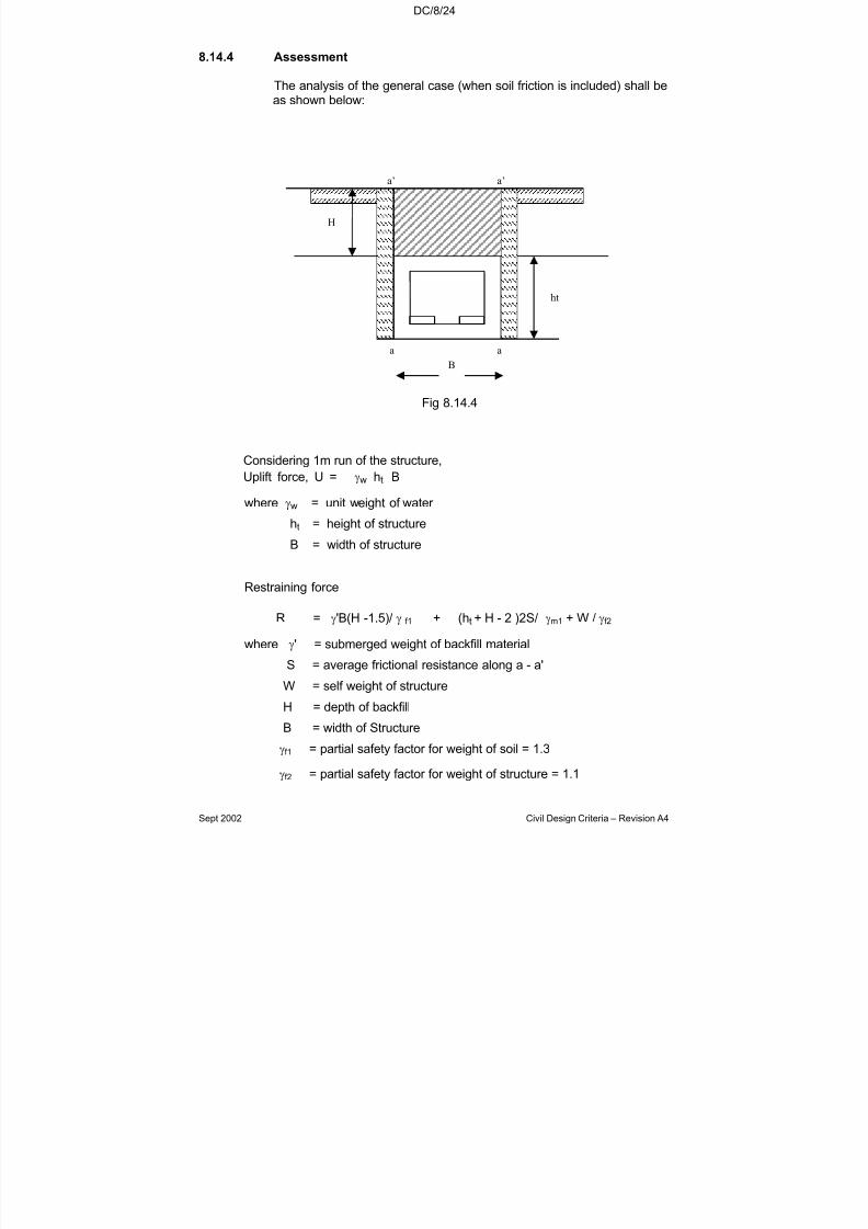
7/18/2019 LTA Civil_standards- Civil Design Criteria
http://slidepdf.com/reader/full/lta-civilstandards-civil-design-criteria 151/345
DC/8/24
Sept 2002 Civil Design Criteria – Revision A4
8.14.4 Assessment
The analysis of the general case (when soil friction is included) shall beas shown below:
Fig 8.14.4
Considering 1m run of the structure,
Uplift force, U = γw ht B
where γw = unit weight of water
ht = height of structure
B = width of structure
Restraining force
R = γ'B(H -1.5)/ γ f1 + (ht + H - 2 )2S/ γm1 + W / γf2
where γ' = submerged weight of backfill material
S = average frictional resistance along a - a'
W = self weight of structure
H = depth of backfill
B = width of Structure
γf1 = partial safety factor for weight of soil = 1.3
γf2 = partial safety factor for weight of structure = 1.1
a’a’
aa
B
H
ht

7/18/2019 LTA Civil_standards- Civil Design Criteria
http://slidepdf.com/reader/full/lta-civilstandards-civil-design-criteria 152/345
DC/8/25
Sept 2002 Civil Design Criteria – Revision A4
γm1 = partial safety factor for shear resistance = 2.0
R / U must be at least 1.1.
8.14.5 Measures to Counteract Flotation
Suitable measures to counteract flotation forces shall be incorporatedin the design. The measure(s) chosen shall suit the particular conditions and method of construction and may include:
(a) Toeing in of the base slab into the surrounding ground or fill.
(b) Increasing the dead weight of the structure by:
(i) Thickening of structural members.
(ii) Providing an extra thickness of concrete beneath thebase slab tied into the structural base slab.
(iii) Deepening diaphragm walls.
(c) The provision of tension piles, but steel tension piles are notacceptable.
It will not normally be acceptable to modify the vertical alignment of thetunnels solely to counteract the flotation forces. The use of groundanchors as a permanent measure to counteract flotation forces shallnot be permitted.
Where the base slab is toed into the surrounding ground or fill, theshear resistance may be obtained from the shear resistance of theground or fill as appropriate. The shear resistance of the ground or fillabove the toe shall be divided by a partial safety factor 2.0 and theadhesion factor shall not apply. The value of the weight of groundabove the toe shall be calculated as for the backfill material, unlessmass concrete is used. Where toes are provided, the minimum toeprojection shall be 0.5m.
The value of the weight of any additional thickness of concrete shalltake into account the increased volume of water displaced.
8.15 STABILITY OF THE EXCAVATION
The stability of the completed structure against failure due to baseheave under the structure shall be checked. In the following equationbased on the analysis by Bjerrum and Eide [3], a partial factor of safetyof 1.15 shall be applied to the disturbing pressure due to the weight of ground beside the structure, with the exception of soil type E
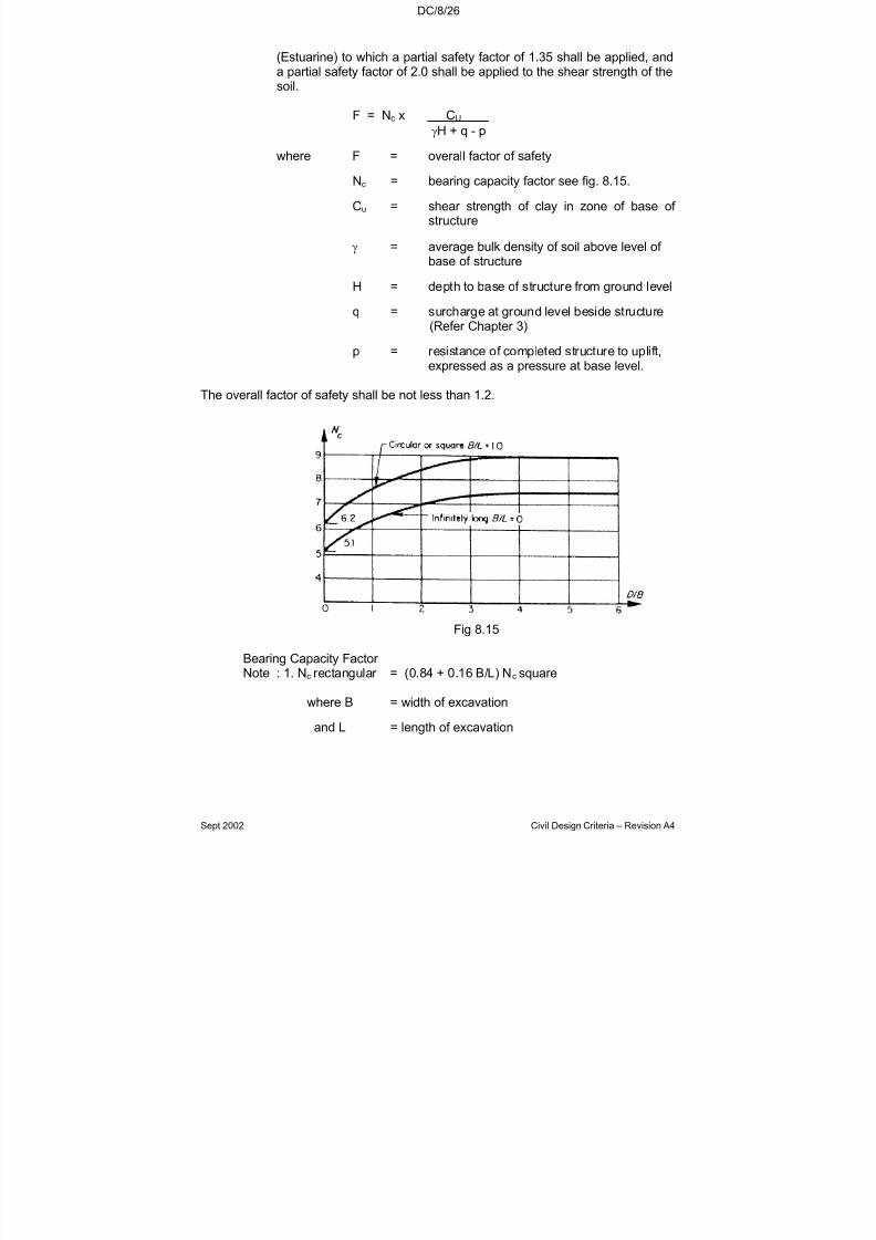
7/18/2019 LTA Civil_standards- Civil Design Criteria
http://slidepdf.com/reader/full/lta-civilstandards-civil-design-criteria 153/345
DC/8/26
Sept 2002 Civil Design Criteria – Revision A4
(Estuarine) to which a partial safety factor of 1.35 shall be applied, anda partial safety factor of 2.0 shall be applied to the shear strength of thesoil.
F = Nc x CU
γH + q - p
where F = overall factor of safety
Nc = bearing capacity factor see fig. 8.15.
Cu = shear strength of clay in zone of base of structure
γ = average bulk density of soil above level of base of structure
H = depth to base of structure from ground level
q = surcharge at ground level beside structure
(Refer Chapter 3)
p = resistance of completed structure to uplift,expressed as a pressure at base level.
The overall factor of safety shall be not less than 1.2.
Fig 8.15
Bearing Capacity Factor Note : 1. Nc rectangular = (0.84 + 0.16 B/L) Nc square
where B = width of excavation
and L = length of excavation
7/18/2019 LTA Civil_standards- Civil Design Criteria
http://slidepdf.com/reader/full/lta-civilstandards-civil-design-criteria 154/345
DC/8/27
Sept 2002 Civil Design Criteria – Revision A4
8.16 WATERPROOFING
8.16.1 Underground structures shall incorporate the following waterproofingmeasures:
(a) All construction joints in external slabs and walls shall beprovided with hydrophilic rubber strips or equivalent measures.
Lining walls cast against diaphragm walls, pile walls or similar shall be regarded as external walls.
(b) A positive waterproofing system (waterproofing admixtureand/or membrane) shall be provided to all base slabs.
(c) A membrane waterproofing system shall be provided above allunderground roof slabs, comprising:
(i) At least two layers of membrane fully bonded with abituminous based system to the concrete structure after application of an appropriate primer. Membranes shallbe of sufficient thickness and provided with additionalprotective layers as necessary to ensure that no damageoccurs. The membrane shall be properly sealed at
junctions with upstand structures.
(ii) An in-situ concrete protective slab.
Diaphragm walls or similar works installed for excavationsupport shall not be left continuously protruding above roof slablevels in such a manner as to allow sub-surface ponding of water. Top surface of the roof slabs shall be profiled to
maintain transverse falls from centre line outwards todiscourage any ponding of water.
(d) External faces of all perimeter walls to underground structuresconstructed in open excavations within stabilised side slopes or in excavations within sheet piling shall be protected by anapplied membrane system similar to, and continuous with, themembranes applied to the roof and base slabs. Protectivelayers shall be applied as appropriate to avoid damage.
(e) Diaphragm walls shall be provided with vertical waterbars at
panel joints. Provision shall be made for acrylic resin or similar injection at the panel joints over the full thickness of the baseslab and roof slab.
(f) Diaphragm and secant pile walls, and similar types of construction shall be faced with cast in-situ reinforced concreteirrespective of whatever else may be provided to enhancewater-tightness or dispose of any seepage.
(h) Joints between roof slabs, base slabs and diaphragm or secantpile walls shall be sealed using hydrophilic rubber and bentonite
7/18/2019 LTA Civil_standards- Civil Design Criteria
http://slidepdf.com/reader/full/lta-civilstandards-civil-design-criteria 155/345
DC/8/28
Sept 2002 Civil Design Criteria – Revision A4
in a suitable matrix, or equivalent means. At least two runs of sealing strip shall be provided along each joint
8.16.2 The selection of materials to be used shall be based on life cycle costassessment of feasible options in accordance with Clause 1.6.4.
8.16.3 The leakage rates for any completed portion of an underground
structure shall be zero.
8.17 DESIGN OF TEMPORARY WORKS
8.17.1 General Requirements
8.17.1.1 Temporary works shall be designed in accordance with the relevantSingapore and British Standards (see Chapter 1). In particular, thedesign of Earth Retaining Structures shall comply with BS 8002 (notCP4) in conjunction with BS 449 for steelwork and BS 8081 for groundanchors. No overstress, other than that allowed in BS 8002, shall be
used in the design. In accordance with BS 8002 Clause 4.5.2.2 thetemporary retaining works shall be designed to accommodate thepossible failure of an individual strut, tie rod or ground anchor using themodified material strengths specified. Temporary Works design maytake into account the limited duration over which the temporary worksare expected to function with respect to durability and loadingdependant on return period (e.g. wind loads). The calculations anddrawings shall make clear where provision for limited life has beentaken into account, particularly where this may have a significantinfluence on the stability of the temporary works.
8.17.1.2 Surcharge load as defined in Chapter 3 shall be used in the design of temporary works.
The design of temporary works shall take account of all the appliedexternal forces and imposed structural deformations, and, additionallyfor underground works, the effects of removal of load from the groundand the movement of the ground independent of the load.
8.17.1.3 Calculations shall be provided to show that the toe-in depth of thetemporary wall or permanent wall used also as a temporary structureprovides adequate passive reaction taking deflection into consideration,
and that the wall will not be overstressed, nor will it deflect excessivelyand will provide adequate protection against the ingress of groundwater into the excavation.
Temporary works design shall include, where appropriate, adequateprecautions against base heave in the soft clays during construction.The stability of the bottom of the excavation shall be checked inaccordance with the analysis of Bjerrum and Eide [3]. Surcharge loadshall be allowed for and applied at ground level to the groundsurrounding the excavation. Failures such as bottom heave, inwardyielding, piping or blows, etc. shall also be considered.
7/18/2019 LTA Civil_standards- Civil Design Criteria
http://slidepdf.com/reader/full/lta-civilstandards-civil-design-criteria 156/345
DC/8/29
Sept 2002 Civil Design Criteria – Revision A4
8.17.1.4 The design shall minimise reduction in piezometric pressures outsidethe excavation. The design shall include seepage analysis andassessments of settlements due to changes in piezometric pressures.
8.17.2 Design of Temporary Excavation Support
Excavations may be supported by diaphragm walls, secant piles or similar Works that may or may not later be incorporated into thepermanent structure. However, whether or not incorporated into thePermanent Works, the design of retaining walls shall include a proper step-by-step analysis incorporating progressive change in porewater pressures, boundary conditions and loading all as the excavationproceeds and as the excavation is subsequently backfilled, and whereappropriate reflecting incorporation of the wall into the permanentworks (refer Clause 1.3.3).
To minimise settlements, where possible earth retaining walls and
strutting arrangements shall be selected to ensure that equal loading isapplied at opposite ends of struts. In cases where the loading isunbalanced the design of the temporary wall and the strutting systemshall similarly include a step-by-step analysis addressing theunbalanced movement necessary to achieve strut loading equilibriumand compatibility of wall movements (accounting for axial shortening of struts. In such cases it is preferred that both (opposite) walls areanalysed in the one model.
Braced excavations shall be analysed by finite element or finitedifference methods in which the changes in ground stresses are
properly related to the deflections which occur in the structuralelements, by the use of appropriate stiffness and other parameters.Relevant empirical evidence from similar excavations must be referredto in support of the conclusions of the analyses. Simplified analyticalmodels and methods may be used to evaluate the variouspermutations of structure geometry and loading, provided that sufficientfinite element/difference analysis has initially been performed for calibration purposes.
Risk assessment reports for existing structures shall be properlyrelated to the conclusions of the excavation analyses.
8.17.3 Design for Removal of Temporary Works
Temporary Works shall be designed as far as possible to be removedwhen no longer required, and not left in the ground. Where TemporaryWorks are to be removed, suitable methods shall be employed tominimise the ground settlement resulting from extraction, for exampleinstallation of grout tubes along piles to facilitate continuous groutingduring their extraction.

7/18/2019 LTA Civil_standards- Civil Design Criteria
http://slidepdf.com/reader/full/lta-civilstandards-civil-design-criteria 157/345
DC/8/30
Sept 2002 Civil Design Criteria – Revision A4
All Temporary Works outside the limits of the following shall bedesigned for removal:
(a) For road projects, the smaller of the road reserve and an areabounded by a line 3m from the footprint of the Permanent Works
(b) For railway projects, the smaller of the Railway Area (as defined
in the Rapid Transit Systems Act) and an area bounded by a line3m from the footprint of the Permanent Works
Temporary Works within the above limits which are incapable of beingremoved or are not desirable to be removed for sound engineeringreasons shall be designed so that there will be no risk of groundsettlement or other deleterious effects as a consequence of decay of timber or other material. To provide a clear way for future utilities, allTemporary Works that are not to be removed shall be designed to bebroken out/cut off to a depth of 2 metres below the finished groundlevel unless shown otherwise on the Authority’s Drawings. This shall
also apply to all secant and diaphragm walls including guidewalls.
Details of the construction sequence assumed, identification of theTemporary Works that are not to be removed (if any) and provisionsmade in the design to satisfy the above requirements shall be detailedon the Temporary Works design drawings. The Temporary Works notbeing removed shall also be shown on the as-built drawings.
8.17.4 Use of Finite Element or Finite Difference Modelling Techniques
Refer to Chapter 6.
8.17.5 Minimum Unplanned Excavation
The design shall allow for minimum unplanned excavation inaccordance with BS 8002 Clause 3.2.2.2.
8.17.6 Temporary Ground Anchorages
8.17.6.1 General
The term ‘ground anchorage’ shall be as defined in BS 8081.
Any anchorage which has had an external load applied to it as part of the installation process shall be designed and constructed to bedestressed before it is buried or covered by any part of the permanentworks.
8.17.6.2 Design Requirements
The design of ground anchorages shall comply with BS 8081.
7/18/2019 LTA Civil_standards- Civil Design Criteria
http://slidepdf.com/reader/full/lta-civilstandards-civil-design-criteria 158/345
DC/8/31
Sept 2002 Civil Design Criteria – Revision A4
All anchorages which are installed either wholly or in part outside theRailway Area or Road Reserve shall be made of non-metallic materialor shall be designed to be removable.
8.17.6.3 Testing of Ground Anchorages
The following notes shall be shown on the Temporary Works design
drawings:
The testing of all anchorages shall consist of proving tests, on-sitesuitability tests and on-site acceptance tests. The method of testingshall be in accordance with the recommended procedures set out in BS8081.
Notwithstanding the requirements given in BS 8081, where anchorageshave failed such tests:
• For every anchorage that has failed, 2 replacement anchorages
shall be installed.
• For every anchorage that has failed, 2 more anchorages shall betested.
One test shall be carried out for each different stratum where theanchorages are installed.

7/18/2019 LTA Civil_standards- Civil Design Criteria
http://slidepdf.com/reader/full/lta-civilstandards-civil-design-criteria 159/345
DC/8/32
Sept 2002 Civil Design Criteria – Revision A4
* Adopt max WT at GL with surcharge, WT at Design Flood Level without surcharge∆
ULS combination for structures designed to BS 5400: load factors shall be obtained from
Design Criteria Clause 8.8.1.2
MAXIMUM VERTICAL & MAXIMUM HORIZONTAL LOAD
RHS SIMILAR(NOT SHOWNFOR BREVITY)
1.6(1)* + 1.4(2) + 1.4(3)* + 1.6(5)* + 1.4(6) + 1.4(7)* + 1.4(8)* + 1.4(9) + 1.4(10)
FIGURE 8.8.3-A: LOAD COMBINATION 1
ULS COMBINATION FOR STRUCTURES DESIGNED TO SS CP 65 ∆:
WT*
Z
GL
DESIGN FLOOD LEVEL*
(3) WATER PRESSURE*
(2) EARTH PRESSURE(γ’h)
(1) SURCHARGE*
8 WATER PRESSURE*
( 5 ) S U R C H A R G E *
( K o
S )
( 6 ) E A R T H P R E S S U R E
( K o
γ ’ Z )
( 7 ) W A T E
R P R E S S U R E
*
h
(10) INTERNAL DL
(11) INTERNAL LL
(9) HULL DL
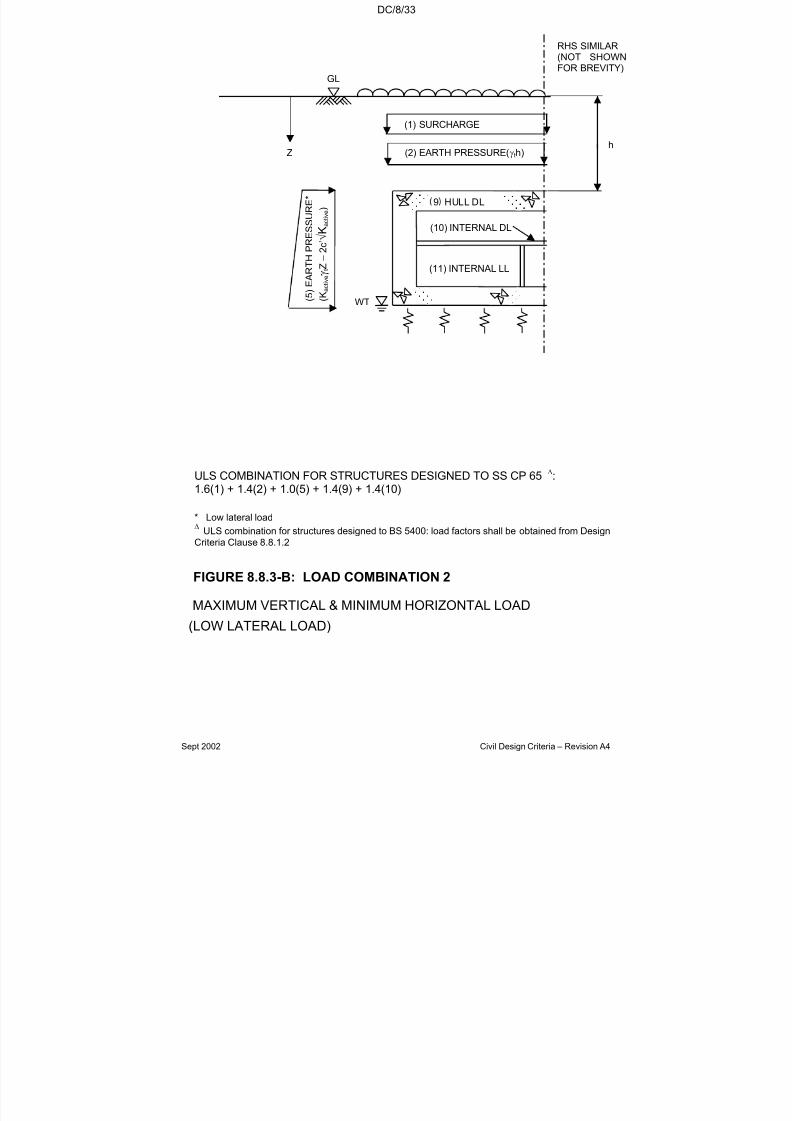
7/18/2019 LTA Civil_standards- Civil Design Criteria
http://slidepdf.com/reader/full/lta-civilstandards-civil-design-criteria 160/345

7/18/2019 LTA Civil_standards- Civil Design Criteria
http://slidepdf.com/reader/full/lta-civilstandards-civil-design-criteria 161/345
DC/8/34
Sept 2002 Civil Design Criteria – Revision A4
h
(3) WATER PRESSURE( wh)
(2)EARTH PRESSURE(γ’h)
(8) WATER PRESSURE (γwZ)
( 5 ) S U R C H A
R G E ( K
o S )
( 6 ) E A R T H P R E S S U R E
( K o
γ ’ Z )
( 7 ) W A T E R P R E S S U R E
( γ w
Z )
MINIMUM VERTICAL & MAXIMUM HORIZONTAL LOAD
FIGURE 8.8.3-C: LOAD COMBINATION 3
WT
Z
GL
RHS SIMILAR(NOT SHOWNFOR BREVITY)
(10) INTERNAL
(9) HULL DL
1.0(2) + 1.0(3) + 1.6(5) + 1.4(6) + 1.2(7) + 1.0(8) + 1.0(9) + 1.0(10)
∆ ULS combination for structures designed to BS 5400: load factors shall be obtained from
Design Criteria Clause 8.8.1.2
ULS COMBINATION FOR STRUCTURES DESIGNED TO SS CP 65 ∆:
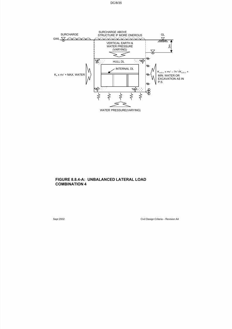
7/18/2019 LTA Civil_standards- Civil Design Criteria
http://slidepdf.com/reader/full/lta-civilstandards-civil-design-criteria 162/345
DC/8/35
Sept 2002 Civil Design Criteria – Revision A4
Kactive x σv’ – 2c’√Kactive +
MIN. WATER OREXCAVATION AS INP.S.
FIGURE 8.8.4-A: UNBALANCED LATERAL LOADCOMBINATION 4
GWL
Ko x σv’ + MAX. WATER
GLSURCHARGE
WATER PRESSURE(VARYING)
3 m
HULL DL
INTERNAL DL
VERTICAL EARTH &WATER PRESSURE
(VARYING)
SURCHARGE ABOVESTRUCTURE IF MORE ONEROUS

7/18/2019 LTA Civil_standards- Civil Design Criteria
http://slidepdf.com/reader/full/lta-civilstandards-civil-design-criteria 163/345
DC/8/36
Sept 2002 Civil Design Criteria – Revision A4
REFERENCES
1. Harrison T.A. - Early-age thermal crack control in concrete(CIRIA report 91).
2. Tomlinson M. J. - Pile Design and Construction Practice.
Viewpoint Publications.
3. Bjerrum L. and Eide O - Stability of strutted excavations in clay.Geotechnique 6. 1956.
7/18/2019 LTA Civil_standards- Civil Design Criteria
http://slidepdf.com/reader/full/lta-civilstandards-civil-design-criteria 164/345
DC/9/1
Sept 2002 Civil Design Criteria – Revision A4
CHAPTER 9
BRIDGES AND ABOVE-GROUND STRUCTURES
9.1 GENERAL
This chapter covers the design requirements for bridge structures andabove-ground structures. Bridge structures include road viaducts,flyovers, MRT and LRT viaducts, footbridges and pedestrian overheadbridges. Above-ground structures include all stations other thanunderground stations, bus shelters, covered linkways, and other similar building structures.
The structures shall generally be of reinforced concrete andprestressed concrete construction. Structural steelwork may beadopted for station roofs, bus shelters and covered linkways whereapplicable. The design of bridges shall utilise prestressed concrete
unless otherwise accepted by the Authority.
Reinforced-earth retaining structures shall not be used for bridgeabutment structures.
9.2 STANDARDS AND CODES OF PRACTICE
Bridge structures shall be designed to BS 5400 Part 4 and UnitedKingdom Highways Agency Departmental Standards (refer to DesignCriteria Clause 1.2.2). Other aboveground structures shall be designed
in accordance with SS CP 65 and BS 5950 as appropriate. Elementsof structures which support both bridges and above-ground structures(either directly or indirectly) shall be deemed to be bridge structuresand shall be designed accordingly.
All water retaining structures shall comply with SS CP 73 unlessotherwise varied by this specification
9.3 ANALYSIS
The structure shall be analysed for the loads and effects specified toobtain the most severe combination of forces on every componentmember. The method and sequence of construction shall be specifiedin the design and taken into account. Possible imperfections infabrication and erection shall be considered in the design and thestructurally acceptable margins of tolerance shall be clearly specifiedfor critical members and operations. The design shall be in accordancewith established good engineering practice and principles and inparticular shall satisfy the specified requirements.

7/18/2019 LTA Civil_standards- Civil Design Criteria
http://slidepdf.com/reader/full/lta-civilstandards-civil-design-criteria 165/345
DC/9/2
Sept 2002 Civil Design Criteria – Revision A4
The design of bridge structures shall satisfy appropriate vibrationserviceability requirements as specified in the relevant clauses of BD37/88 and BD 49/93.
9.4 LOADING
The following loads and effects shall be considered in the design of allstructures:
Dead load
Superimposed dead load
Live load
Wind load
Temperature effects
Restraints at bearings and supports
Effects of shrinkage and creep in concrete
Erection forces and effects
Differential settlement
Effects of bearing replacements
Collision loads
Earth pressures
Any other forces and effects arising out of the special nature of anystructure, for example, prestressed forces.
All design loads shall be in accordance with the loads specified inchapter 3 of the Design Criteria except temperature loads andaerodynamic effects specified in the following clauses.
9.4.1 Temperature loads
Temperature loads shall be considered in accordance with BD 37/88and the following:
(a) Temperature Range
For Singapore, the range of shade air temperature corresponding to a
return period of 120 years shall be taken as ±10°C from a mean
temperature of 27°C and for these shade air temperatures, the extreme
7/18/2019 LTA Civil_standards- Civil Design Criteria
http://slidepdf.com/reader/full/lta-civilstandards-civil-design-criteria 166/345
DC/9/3
Sept 2002 Civil Design Criteria – Revision A4
maximum and minimum mean temperature in the structure given inTable 1 shall be adopted. For a return period of 20 years the shade air
temperature shall be taken as 27°C ± 8°C and the correspondingbridge temperatures given in Table 1 shall be used.
(b) Temperature in Combination with Wind Force
Where forces due to change in temperature are to be considered incombination with maximum wind forces, the temperature range for all
types of structure shall be taken as 27°C ± 5°C.
(c) Temperature Gradient
The effects of local strains resulting from temperature gradients withinthe structure and parts of the structure shall be calculated from thevalues of maximum temperature differences given in Table 1 and Fig 1.The effects of temperature gradient need not be considered incombination with maximum wind force.
(d) Coefficient of Thermal Expansion
The coefficient of thermal expansion for 1.0°C shall be taken as
12x10−6 for steel and concrete.
(e) Temperatures during Erection
For the purpose of taking temperature effects into account at thedesign stage the temperatures given in Table 1 for a return period of 20years shall be used.
(f) Temperature Range for movement joint
The maximum and minimum mean temperature given in Table 1 for areturn period of 120 years are intended to be used in the considerationof main structural elements. Carriageway joints and similar equipmentcan be considered as having a useful life of approximately 20 years*,and hence the relevant figures given in Table 1 may be used.
*Designers must ensure that in adopting this relaxation there is nopossibility of excessive forces being transmitted to main structural
members should the reduced range of temperature effects beexceeded if the full thermal range occurs.
(g) Temperature Range for bridge bearing
Bridge bearings shall be designed for a temperature range of returnperiod 120 years.
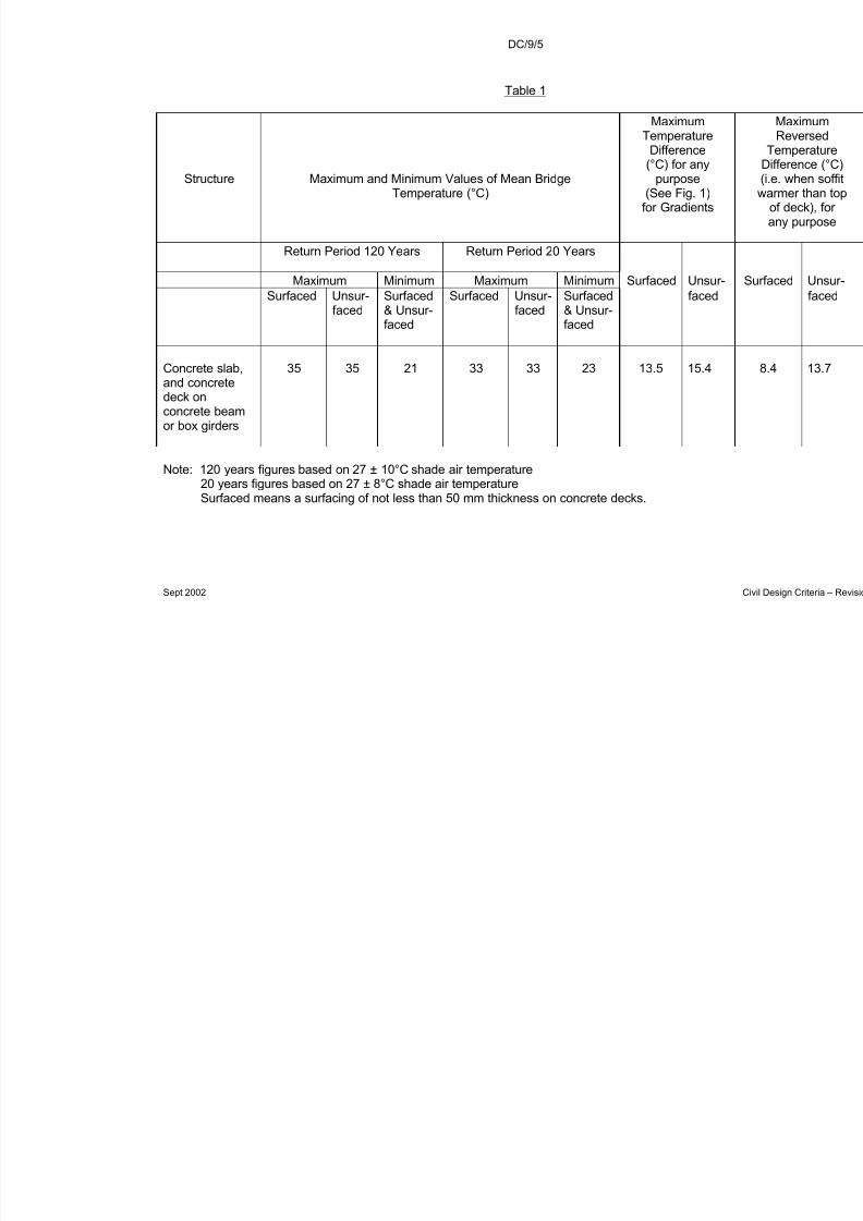
7/18/2019 LTA Civil_standards- Civil Design Criteria
http://slidepdf.com/reader/full/lta-civilstandards-civil-design-criteria 167/345
DC/9/5
Sept 2002
Table 1
Structure Maximum and Minimum Values of Mean BridgeTemperature (°C)
MaximumTemperature
Difference(°C) for any
purpose(See Fig. 1)
for Gradients
Return Period 120 Years Return Period 20 Years
Maximum Minimum Maximum Minimum Surfaced Uns
Surfaced Unsur-
faced
Surfaced
& Unsur-faced
Surfaced Unsur-
faced
Surfaced
& Unsur-faced
face
Concrete slab,and concretedeck onconcrete beamor box girders
35 35 21 33 33 23 13.5 15.4
Note: 120 years figures based on 27 ± 10°C shade air temperature20 years figures based on 27 ± 8°C shade air temperatureSurfaced means a surfacing of not less than 50 mm thickness on concrete decks.
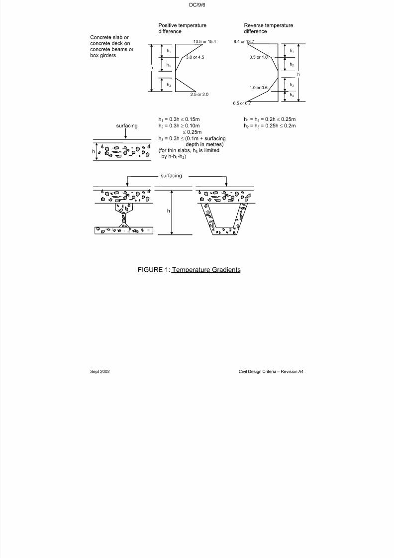
7/18/2019 LTA Civil_standards- Civil Design Criteria
http://slidepdf.com/reader/full/lta-civilstandards-civil-design-criteria 168/345
DC/9/6
Sept 2002 Civil Design Criteria – Revision A4
Positive temperature Reverse temperaturedifference difference
Concrete slab or concrete deck onconcrete beams or box girders
h1 = 0.3h ≤ 0.15m h1 = h4 = 0.2h ≤ 0.25m
surfacing h2 = 0.3h ≥ 0.10m h2 = h3 = 0.25h ≤ 0.2m
≤ 0.25m
h3 = 0.3h ≤ (0.1m + surfacing
depth in metres)(for thin slabs, h3 is limited
by h-h1-h2)
FIGURE 1: Temperature Gradients
13.5 or 15.4 8.4 or 13.7
6.5 or 6.7
h
surfacing
h
3.0 or 4.5 0.5 or 1.0
1.0 or 0.6
2.5 or 2.0
h1
h2
h3
h1
h2
h3
h4
h
h
7/18/2019 LTA Civil_standards- Civil Design Criteria
http://slidepdf.com/reader/full/lta-civilstandards-civil-design-criteria 169/345
DC/9/7
Sept 2002 Civil Design Criteria – Revision A4
9.4.2 Aerodynamic Effects
The design of structures, which may be susceptible to aerodynamiceffects, shall comply with BD 49/93. In addition, where appropriate,design criteria for such effects shall be specially established, andwhere necessary, the behaviour shall be proven to be acceptable bytesting.
9.5 DESIGN CONSIDERATIONS AND REQUIREMENTS
9.5.1 General
The following requirements shall be adhered to in the design:
(a) A minimum headroom clearance of 5.4 metres shall bemaintained across all roads for all structures.
The headroom clearance across Malayan Railway Land andDrainage Reserves etc. shall comply with the requirements of the respective authorities.
(b) A minimum 2 metres clear horizontal separation shall beprovided between the structures of adjacent bridge decksunless stated otherwise.
(c) Columns/Piers
The spacing of link and legs of link shall not exceed 300mm or
0.75 times the effective depth of the section whichever is lesser.
The links shall be of grade 460 steel and the minimum bar diameter shall be 10mm.
The design of columns and piers and the assumed constructionsequence shall be such that the sway at the top of the column-head and/or crosshead during erection does not exceed 10mm.
The longitudinal sway at the top of column-head and/or crosshead under the applied longitudinal loads (e.g. braking
loads) shall not exceed 10mm.
(d) Beams
The area of nominal tension reinforcement shall not be less than0.25% of bd when using grade 460 reinforcement where:
(i) b is the average breadth of the section excluding thecompression flange for T, I and box sections;

7/18/2019 LTA Civil_standards- Civil Design Criteria
http://slidepdf.com/reader/full/lta-civilstandards-civil-design-criteria 170/345
DC/9/8
Sept 2002 Civil Design Criteria – Revision A4
(ii) d is the effective depth to tension reinforcement for T andI sections.
For beams where the depth of the side face exceeds 600mm,longitudinal reinforcement with the minimum area of at least0.12% of bd shall be provided on each face with spacing notexceeding 300mm and the diameter of the bar not less than
16mm. b is the average breadth of the web and d is the effectivedepth to tension reinforcement.
The link requirement outlined in (c) above shall also beapplicable to beams. Where beams are designed to resisttorsion, the spacing of links shall not exceed 200mm.
(e) Access to void
Access to the void of box type sections shall be providedwherever possible. An easily removable access cover to the
void shall be provided in each span. Access to void shall also beprovided in each cell of a continuous box girder at diaphragmlocations to cater for future maintenance and inspection.
(f) Slab
The spacing of bars shall not exceed 200mm and the minimumdiameter of reinforcement bars shall be 13mm.
(g) Load Factors for Station Structures Supported by BridgeStructures
Where station structures are supported by bridge structures, indetermining the load effects of the station structures on thebridge structures, the load factors in BD37/88 for loadcombinations 1 to 5 shall apply.
9.5.2 Reinforced Concrete
The minimum grade of concrete shall be C40.
9.5.3 Prestressed Concrete
(a) General
The maximum and minimum grades of concrete shall be gradeC55 and C40 respectively. The key spanning members of thesuperstructure of bridges shall be designed as prestressedconcrete.
All assumptions made in the determination of the designprestress loads, e.g. vertical and horizontal curvature, frictionand wobble, shrinkage and creep of concrete, elastic
7/18/2019 LTA Civil_standards- Civil Design Criteria
http://slidepdf.com/reader/full/lta-civilstandards-civil-design-criteria 171/345
DC/9/9
Sept 2002 Civil Design Criteria – Revision A4
shortening, properties of concrete and prestressing steel, etc.shall be clearly stated in the calculations and on the drawings.
Prestressing anchorages shall be detailed such that they areeasily accessible for inspection and maintenance. The detailingshall also prevent the accumulation of water and dirt around theanchorage.
(b) Serviceability Limit State
(i) Modification to clauses 4.2.2(a) and (b) of BS5400 Pt.4Prestressed concrete elements of bridge structures shallbe designed as class 1 under load combination 1 andclass 2 under load combinations 2 to 5 respectively. For pedestrian overhead bridges and footbridges, live loadsshall be included in load combinations 1 to 5.
(ii) Prestressed concrete used as station structures that are
exposed to the weather shall be designed as class 1 toclause 4.3.4.3 of SS CP 65. Internal elements, which arefully protected from the weather, may be designed asclass 2.
(iii) Modification to clause 6.3.2 of BS5400 Pt.4:
Clause 6.3.2.2 (b) - Concrete compressive stress limitationsat transfer
The compressive stresses in the concrete at transfer shall not
exceed 0.5 f ci or ≤
0.4 f cu (whichever is less) where f ci is theconcrete strength at transfer and f cu is the characteristicstrength.
Clause 6.3.2.4 (a) (1) - Cracking under service loads for Class 1members
No tensile stress shall be allowed for Class 1 members, exceptas indicated in clause 6.3.2.4(b)(1). In the case of bridgestructures solely prestressed with pre-tensioned tendons, atensile stress of 1 N/mm2 is allowed at the simply supported
ends of spans under load combination 1; however, additionalreinforcement shall be provided and well distributed throughoutthe tensile zone of the section.
Clause 6.3.2.4 (a) (2) - Cracking under service loads for Class 2members
The tensile stresses shall not exceed the design flexural tensile
strength of the concrete, which shall be taken as 0.45√f cu for
pretensioned members, 0.36√f cu for post-tensioned members

7/18/2019 LTA Civil_standards- Civil Design Criteria
http://slidepdf.com/reader/full/lta-civilstandards-civil-design-criteria 172/345
DC/9/10
Sept 2002 Civil Design Criteria – Revision A4
and 0.36√f cu for members which are both pre- and post-tensioned.
Clause 6.3.2.4 (b)(2) - Cracking at transfer and duringconstruction
The flexural tensile stress in the concrete should not exceed the
following values (but see Clause 7.3.3 of BS 5400: Part 4 for joints in post-tensioned segmental construction);
0.45√f ci for pre-tensioned members, 0.36√f ci for post-tensioned
members and 0.36√f ci for members which are both pre- andpost-tensioned under all construction load cases, includingtransfer. Members with pre-tensioned tendons should havesome tendons or additional reinforcement well distributedthroughout the tensile zone of the section and members withpost-tensioned tendons should, if necessary, have additionalreinforcement located near the tension face of the member.
(iv) Modification to Clause 6.7.1 of BS5400: Pt.4 -MaximumInitial Prestress:
Immediately after anchoring, the force in the prestressingtendon shall not exceed 70% of the characteristic strength for both pre-and post-tensioning. The jacking force shall not exceed75% of the characteristic strength during stressing operationsunless written acceptance of the Engineer has been obtained.
9.5.4 Reduction or Isolation of Vibration
In the selection of the structural framework for railway stations, carefulconsideration shall be given to the isolation or reduction of vibrationtransmitted from bridge structures to the station structures. Completeisolation shall be adhered to if practical.
9.5.5 Design Surface Crack Width
For the serviceability limit state of cracking:
(a) Design surface crack width of reinforced concrete bridge
structures shall not exceed the values given in Table 1 of BS5400: Part 4 or 0.2mm whichever is the lesser:
(b) Design crack width of reinforced concrete station structuresexposed to weather shall not exceed 0.2mm. The minimumconditions of exposure as per SS CP 65 Part 1 Table 3.2 shallbe taken as severe for external elements of station structures,and as moderate only for those internal elements of stationstructures, which are completely sheltered from rain.
7/18/2019 LTA Civil_standards- Civil Design Criteria
http://slidepdf.com/reader/full/lta-civilstandards-civil-design-criteria 173/345
DC/9/11
Sept 2002 Civil Design Criteria – Revision A4
9.5.6 Member Shapes and Sizing
A prime objective of the design is that the appearance of the finishedstructures shall be aesthetically pleasing and shall enhance theenvironment in which it is located. Due attention shall be given at theconcept stage of the design to all aspects of the appearance of thestructure in order to ensure that the appearance of the final structure
as built is neither heavy nor bulky, but is rather slender and graceful,and in harmony with environment. The concept design shall besubmitted in order to demonstrate to the acceptance of the Engineer that this objective will be met, before proceeding to detailed design.
In sizing the structural members, the Contractor shall fulfill thefollowing conditions:(a) Change in sectional depth, (if necessary) shall be gradual. No
abrupt change in sectional depth shall be allowed for any part of the structure.
(b) A change of shape of section, other than that due to varyingdepth, is generally unacceptable. A uniform shape shall beadopted throughout the length of the structure to give a pleasingappearance.
(c) For road bridge structures with constant beam depth, the beamdepth shall not exceed 2.2m (inclusive of deck) for normalspans of up to 40m under normal circumstances. In exceptionalcases, where this beam depth has to be exceeded, theContractor shall obtain the written acceptance of the Engineer,prior to submission of tender.
(d) For road bridge structures with variable beam depth, the beamdepth shall be agreed with the Engineer.
(e) The column sizing shall be done such that it gives anappearance of a slender structure proportionate to thesuperstructure. “Wall” like columns are generally displeasing tothe eye and should be avoided.
9.5.7 Precast Segments
The design of the precast segments match cast with dry joints shall besuch that there is a minimum 2.0 N/mm2 compressive stress acrossthe whole section of the precast segment under all load combinations.
The design of the precast segment match cast with epoxied joints shallallow for a minimum 1.0 N/mm2 compressive stress across the wholesection of the precast segment under all load combinations except thataminimum of 1.5 N/mm2 compressive stress shall be required acrossthe insitu stitches of the precast segment under all load combinations.
7/18/2019 LTA Civil_standards- Civil Design Criteria
http://slidepdf.com/reader/full/lta-civilstandards-civil-design-criteria 174/345

7/18/2019 LTA Civil_standards- Civil Design Criteria
http://slidepdf.com/reader/full/lta-civilstandards-civil-design-criteria 175/345
DC/9/13
Sept 2002 Civil Design Criteria – Revision A4
a rigid structure to a flexible structure as specified in Chapter 6 of theDesign Criteria.
9.6 BEARINGS
9.6.1 General
With the exception of those used only for pedestrians, all bridges shalluse only confined elastomeric bearings (mechanical pot bearings). Themanufacture, installation and performance of the bearings shall strictlycomply with the M & W Specification Section 15. For bridges used onlyfor pedestrians, pot bearings are acceptable, but other bearing typesmay be proposed subject to the acceptance of the Engineer.
The design of the bridge shall as far as possible minimise the number of bearings so as to reduce future maintenance. Consideration shall begiven for the easy maintenance and replacement of bearings.
Bearings for railway bridges shall be designed to accommodate thederailment loads specified in clause 8.5 of BD 37/88. Thecorresponding viaduct rotation under derailment loads shall becontrolled to minimise damage to viaduct elements.
9.6.2 Bearing Replacement
Bearings shall be designed so that the deck can be jacked off thecolumn heads without the need for temporary works to accommodatebearing replacement. The bridge supports (columns, column heads
etc.) and the deck (diaphragms etc.) shall be designed accordingly toaccommodate this. The design shall ensure that sufficient space hasbeen allowed for the placement of jacks for future replacement of thebearings on the supporting structure without the necessity for erectionof temporary support. Drawings showing the details of thereplacement of bearings shall be produced as part of the designdrawings.
9.7 MOVEMENT JOINTS FOR DECKING SLABS
9.7.1 Definitions
a) The term “movement joint” covers all types of permanent jointor hinge throat which allows expansion, contraction or angular rotations to occur.
b) The term “fabricated movement joint” covers proprietarymanufactured assemblies designed to carry traffic smoothlyover movement joints and seal them against the ingress of water and debris.

7/18/2019 LTA Civil_standards- Civil Design Criteria
http://slidepdf.com/reader/full/lta-civilstandards-civil-design-criteria 176/345
DC/9/14
Sept 2002 Civil Design Criteria – Revision A4
c) The term “movement joint formed in place” covers themeasures taken in the course of construction to permit adjacentstructural members to move relative to each other withoutdamage.
9.7.2 General
Movement joints for road viaducts, flyovers, and bridge structures shallbe heavy-duty surface mounted mechanical system with bolts andreinforcement embedded in the bridge deck. They shall be providedalong the full width of the bridge deck including the parapets, strictly inaccordance with the manufacturer’s recommendations.
The design of the bridge shall minimise the number of movement jointson the deck as far as possible to reduce future maintenance.Nevertheless, movement joints with movement capacity greater than100mm shall not be used.
Movement joints in railway station shall be located so as to avoiddamage to the architectural finishes. They shall accommodateshrinkage, creep and thermal effects. They shall be designed to beeasily maintained and replaceable.
9.7.3 Movement Joints
The Contractor shall submit to the Engineer, for acceptance, details of the joints he proposes to use. When submitting the details of expansion joints, the size, length and spacing of the holding-down bolts
shall be given, together with calculations recording the movements for which the proposed joints have been designed, deriving the resultingloads generated by the joints in accommodating these movements,and demonstrating that the bridge structure is capable of withstandingthese movements and loadings. A detailed drawing clearly indicatingthe various dimensions and sections of the joints shall be submitted tothe Engineer for acceptance.
Movement joints shall be either completely sealed to prevent ingress of water and granular material, or alternatively, provision shall be madefor carrying away any water and granular material penetrating the joint.
Movement joints shall be designed to enable maintenance to becarried out with ease, and parts liable to wear shall be easilyreplaceable.
Any significant area of a movement joint exposed at road level shall besurface treated to prevent skidding.
Movement joints shall not unduly impair the riding quality of thesurrounding road surface for vehicular traffic, nor shall the passage of

7/18/2019 LTA Civil_standards- Civil Design Criteria
http://slidepdf.com/reader/full/lta-civilstandards-civil-design-criteria 177/345
DC/9/15
Sept 2002 Civil Design Criteria – Revision A4
vehicular traffic cause undue noise or vibration. The size of any opengap on the riding surface of the joint shall not exceed 50mm.Wherever it is appropriate, movement joints for structures shall bedesigned so that the passage of pedestrians and cyclists is notimpeded.
9.8 WATERPROOFING AND MECHANICAL IRRIGATION SYSTEM FORFLOWER TROUGH IN ROAD VIADUCTS AND PEDESTRIAN
OVERHEAD BRIDGES
A waterproofing agent shall be applied to the inner surface of theflower trough as specified in Chapter 13 of the M & W Specification.The waterproofing material shall be submitted for Engineer’sacceptance.
The design, supply and installation of the mechanical irrigation systemfor flower troughs in road viaducts and pedestrian overhead bridges
shall comply with the requirements of the National Parks Board. Thehydraulic calculations shall be submitted to the relevant authority for approval.
9.9 PARAPET SYSTEM ON VEHICULAR BRIDGES AND PEDESTRIAN
OVERHEAD BRIDGES
9.9.1 General
The design of parapet systems for bridges shall satisfy the
requirements of the British Standard Code of Practice BS 6779: Part 1to 3, BD 52/93 and the details shown on the Authority’s Drawings.
Dimensions shown on the Authority’s Drawings shall take precedenceover those specified in the BS 6779: Part 1 to 3 and BD 52/93.
The design of bridge parapet systems shall generally conform to theBS 6779: Part 1 to 3 and BD 52/93 with the following exceptions:
a) Of the six groups of bridge parapets outlined in BD 52/93, onlythree groups of parapets, namely Groups P1, P4 and P6 shall
be used as follows:
Group P1 - With the exception of bridges over high-risklocations such as MRT and railway lines, group P1vehicle parapets shall be used for all road bridges.
Group P4 - Pedestrian parapets in vehicular bridges andpedestrian overhead bridges where there is nochance of being hit by errant vehicles.
7/18/2019 LTA Civil_standards- Civil Design Criteria
http://slidepdf.com/reader/full/lta-civilstandards-civil-design-criteria 178/345
DC/9/16
Sept 2002 Civil Design Criteria – Revision A4
Group P6 - High containment parapets for bridges carryingroads over high-risk locations such as MRT andrailway lines.
b) Only 2-rail aluminium alloy railings mounted on a concreteparapet for Group P1 vehicle parapet and a full height concreteparapet for Group P6 high containment parapet shall be used.
c) Parapet railings including posts shall be of aluminium alloy for group P1. Parapet railings including posts shall be of aluminiumalloy or stainless steel for group P4. All fixing bolts shall be of high-grade stainless steel metal with minimum yield strength of 450 N/mm2.
d) Group P1 vehicle parapets and Group P6 high containmentparapets shall have a minimum height of 1.5m above theadjacent paved surface.
e) The width of the adjoining paved surface between the trafficface of the parapet and the edge of the carriagewayhardshoulder or verge shall be 300mm for arterial roads and600mm for semi-expressways and expressways. A 75mmsplayed kerb shall be provided behind the edge of hardshoulder.The adjoining paved surface shall fall towards the top of thekerb.
f) For the purposes of calculating the vehicular impact loading asspecified in Clause 7.1 of the BS 6779:Part 3, the effectivelongitudinal member for the concrete panel alone shall be taken
as 1 irrespective of the height of the panel for Group P1parapets.
9.9.2 Additional Design Requirements on Vehicular Bridge Parapets
To prevent vehicles on the bridge approaches from striking the end of a vehicular bridge parapet, safety fences shall be provided.
When the safety fence is not connected to the parapet, it should bearranged to overlap the end of the parapet by not less than 300mm onthe traffic side.
Where there is a risk of the back of the fence being struck by a vehicleleaving the opposing carriageway, the fence shall have a rail on eachside of the posts.
The supports for gantries, directional and information signs etc. shallbe integrated with the bridge parapet. The shape of supports mustblend in with the profile of the bridge and shall be subject to theapproval of the Engineer.

7/18/2019 LTA Civil_standards- Civil Design Criteria
http://slidepdf.com/reader/full/lta-civilstandards-civil-design-criteria 179/345
DC/9/17
Sept 2002 Civil Design Criteria – Revision A4
9.10 THERMAL RAIL FORCES
Provision shall be made for horizontal transverse and longitudinalforces due to temperature variation in the rail on railway bridges. Theforces shall be applied in a horizontal plane at the top of the low rail asfollows:
(1) Transverse Force: The transverse force (T) per linear metre of structure per rail shall be determined by the following formula:
T= 535/R (KN)
Where R is the radius of rail curvature in metre.
(2) Longitudinal Force: A longitudinal force of 180 kN per rail shallbe applied to the first 3 columns or piers adjoining any abutmentor cross-over structure.
9.11 RAILWAY DECK FURNITURE, DRAINAGE AND WATERPROOFING
The railway deck furniture, drainage and waterproofing system shall bedesigned for all effects and requirements of the railway including25mm vertical lift for bearing replacement as specified in M & WSpecification Section 15. The extra 10mm vertical lift is in addition to15mm limiting vertical lift for railway bridge beams as specified in M &W Specification Section 15 is the tolerance required for bearingreplacement.
9.12 ELECTRICAL AND MECHANICAL REQUIREMENTS
Electrical and Mechanical (E&M) requirements must be considered inthe development of all structural designs. Such consideration shouldinclude the following:
(a) The incorporation of stray current corrosion control systems for railway bridges by provision of a continuous conductor for straycurrents to return to the substations in order to reduce the
possibility of stray direct currents entering the viaduct structure.
(b) The incorporation of an adequate water drainage system for allstructures.
(c) Reinforcement in the plinth and deck designed to avoidinterference with attenuation of the signalling circuits of railwayviaducts.
7/18/2019 LTA Civil_standards- Civil Design Criteria
http://slidepdf.com/reader/full/lta-civilstandards-civil-design-criteria 180/345
DC/9/18
Sept 2002 Civil Design Criteria – Revision A4
(d) Special care shall be taken over the location of gullies at pointsand crossing areas of railway bridge structures.
E&M requirements are liable to change as the design of various E&Mcontracts are developed. The design shall be co-ordinated with theE&M Contractors and shall incorporate their final requirements, andshow them on final design and working drawings.
All E&M details shall be subject to the approval of the Authority’s E&MDepartment.
7/18/2019 LTA Civil_standards- Civil Design Criteria
http://slidepdf.com/reader/full/lta-civilstandards-civil-design-criteria 181/345

7/18/2019 LTA Civil_standards- Civil Design Criteria
http://slidepdf.com/reader/full/lta-civilstandards-civil-design-criteria 182/345
DC/10/2
Sept 2002 Civil Design Criteria – Revision A4
10.3 ROAD GEOMETRY
The geometric design of road shall be as follows:-
10.3.1 Horizontal Alignment
10.3.1.1 Main Carriageway
Arterial RoadExpressway Major Minor
(a) Design Speed,(km/h)
90 *1
80 *270 60
(b) Desirable MinimumRadius, (m)
355 (for 90 km/h)
265 (for 80 km/h)
200 140
(c) Absolute Minimum
Radius, (m)
335 (for 90 km/h)
250 (for 80 km/h)
190 135
(d) Desirable MaximumSuperelevation
5% 5% 5%
(e) Absolute MaximumSuperelevation
Notes:
6% 6% 6%
*1apply to at-grade and elevated structures
*2apply to tunnel, underpass and depressed section
10.3.1.2 Interchange’s Ramp & Loop,Turning Roadway/Slip Road
Expressway toExpressway
Others
(a) Minimum Design Speed,(km/h)
60 50
(b) Minimum Radius, (m) 135 90
(c) Absolute MaximumSuperelevation
6% 6%

7/18/2019 LTA Civil_standards- Civil Design Criteria
http://slidepdf.com/reader/full/lta-civilstandards-civil-design-criteria 183/345
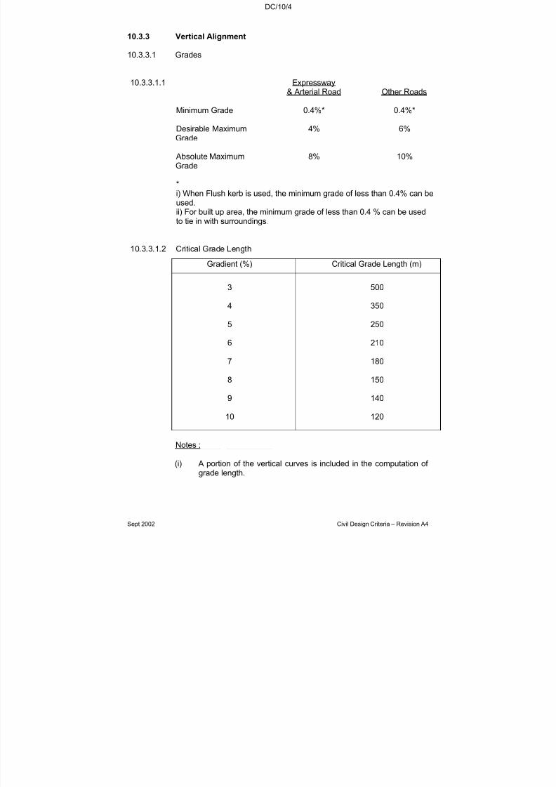
7/18/2019 LTA Civil_standards- Civil Design Criteria
http://slidepdf.com/reader/full/lta-civilstandards-civil-design-criteria 184/345
DC/10/4
Sept 2002 Civil Design Criteria – Revision A4
10.3.3 Vertical Alignment
10.3.3.1 Grades
10.3.3.1.1 Expressway& Arterial Road Other Roads
Minimum Grade 0.4%* 0.4%*
Desirable MaximumGrade
4% 6%
Absolute MaximumGrade
8% 10%
*i) When Flush kerb is used, the minimum grade of less than 0.4% can be
used.ii) For built up area, the minimum grade of less than 0.4 % can be usedto tie in with surroundings.
10.3.3.1.2 Critical Grade Length
Gradient (%) Critical Grade Length (m)
3 500
4 350
5 250
6 210
7 180
8 150
9 140
10 120
Notes :
(i) A portion of the vertical curves is included in the computation of grade length.
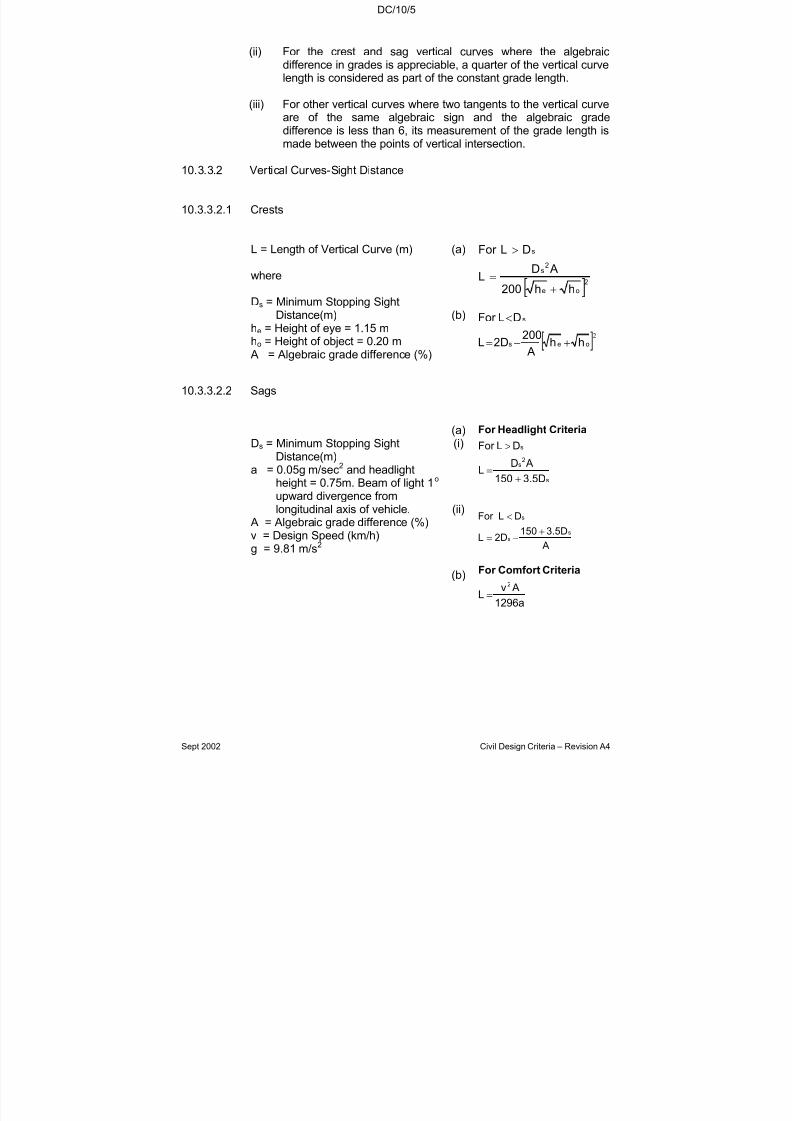
7/18/2019 LTA Civil_standards- Civil Design Criteria
http://slidepdf.com/reader/full/lta-civilstandards-civil-design-criteria 185/345
DC/10/5
Sept 2002 Civil Design Criteria – Revision A4
(ii) For the crest and sag vertical curves where the algebraicdifference in grades is appreciable, a quarter of the vertical curvelength is considered as part of the constant grade length.
(iii) For other vertical curves where two tangents to the vertical curveare of the same algebraic sign and the algebraic gradedifference is less than 6, its measurement of the grade length is
made between the points of vertical intersection.
10.3.3.2 Vertical Curves-Sight Distance
10.3.3.2.1 Crests
L = Length of Vertical Curve (m)
where
Ds = Minimum Stopping SightDistance(m)
he = Height of eye = 1.15 mho = Height of object = 0.20 m
A = Algebraic grade difference (%)
(a)
(b)[ ]
2
oe
2s
s
hh200
ADL
DLFor
+
=
>
[ ]2oes
s
hh A
200 2DL
DL For
+−=
<
10.3.3.2.2 Sags
Ds = Minimum Stopping SightDistance(m)
a = 0.05g m/sec2
and headlightheight = 0.75m. Beam of light 1o
upward divergence fromlongitudinal axis of vehicle.
A = Algebraic grade difference (%)v = Design Speed (km/h)g = 9.81 m/s2
(a)(i)
(ii)
(b)
s
2s
s
3.5D150
ADL
DLFor
+
=
>
CriteriaHeadlightFor
A
3.5D1502DL
DL For
ss
s
+−=
<
1296a
AvL
2
=
CriteriaComfortFor

7/18/2019 LTA Civil_standards- Civil Design Criteria
http://slidepdf.com/reader/full/lta-civilstandards-civil-design-criteria 186/345
DC/10/6
Sept 2002 Civil Design Criteria – Revision A4
10.3.4 Vertical Curves
Vertical curves are provided whenever there is a change in grade. Thesymmetrical simple parabolic curves are preferred for vertical curves asthey give a constant rate of change in grade throughout the curve. Thelength of the vertical curve must also provide for sufficient visibility andcomfort requirements.
10.3.5 Compound Curves
Wherever possible, compound curve shall be avoided in favour of asimple long curve. If it is not possible, the radius of the flatter curveshall not be greater than 50% of the sharper curve.
10.3.6 Reverse Curves and Broken-Back Curves
10.3.6.1 A reverse curve consists of two curves of opposite hand with acommon tangent point. Reverse curves using transition curves are
acceptable. However, reverse curves using plain circular curves shallbe avoided unless large radii as specified in Clause 10.3.10.1 are used.Where it is unavoidable to have two circular curves of opposite handclose together, they shall be separated by a tangent of sufficient lengthfor the development of the superelevation. The minimum lengthrequired for the development of superelevation is specified in Clause10.3.10.3.
10.3.6.2 Broken-back curves consists of two curves of the same hand joinedtogether by a short stretch of tangent. Where possible, broken-backcurves shall be replaced by a single curve or a compound curve if it is
not feasible. The length in metres of the tangent shall not be less than 3times the design speed in km/h.
10.3.7 Corner Radius
The corner radii provided at an intersection have a considerable effecton the operation and safety of the intersection. In residential areaswhere the volumes of buses and trucks are low or negligible, theminimum radius of 6m is usually sufficient. For driveways leading toresidential houses, the radius may be reduced to 3m if theencroachment made by the turning passenger car does not affect the
through traffic significantly. At busy intersections with substantialvolumes of heavy vehicles, a turning radius of more than 12m shall beprovided. Provision of larger radius would minimise the need for theheavy vehicles to swing out of the lane to make a turn.
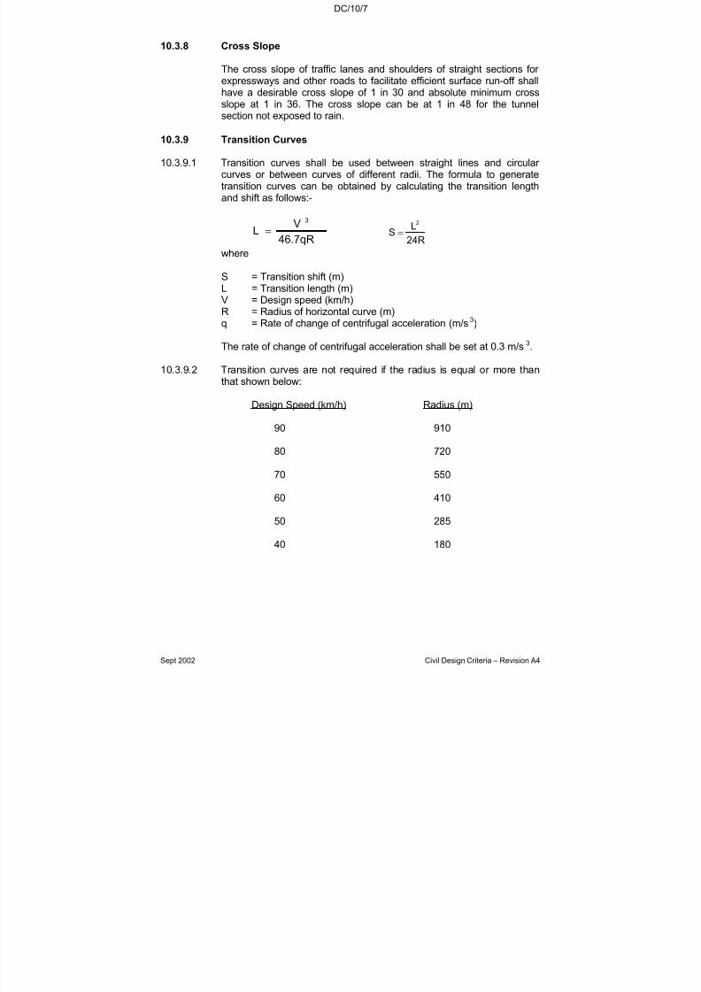
7/18/2019 LTA Civil_standards- Civil Design Criteria
http://slidepdf.com/reader/full/lta-civilstandards-civil-design-criteria 187/345
DC/10/7
Sept 2002 Civil Design Criteria – Revision A4
10.3.8 Cross Slope
The cross slope of traffic lanes and shoulders of straight sections for expressways and other roads to facilitate efficient surface run-off shallhave a desirable cross slope of 1 in 30 and absolute minimum crossslope at 1 in 36. The cross slope can be at 1 in 48 for the tunnelsection not exposed to rain.
10.3.9 Transition Curves
10.3.9.1 Transition curves shall be used between straight lines and circular curves or between curves of different radii. The formula to generatetransition curves can be obtained by calculating the transition lengthand shift as follows:-
46.7qR
VL
3
= 24R
LS
2
=
where
S = Transition shift (m)L = Transition length (m)V = Design speed (km/h)R = Radius of horizontal curve (m)q = Rate of change of centrifugal acceleration (m/s3)
The rate of change of centrifugal acceleration shall be set at 0.3 m/s3.
10.3.9.2 Transition curves are not required if the radius is equal or more than
that shown below:
Design Speed (km/h) Radius (m)
90 910
80 720
70 550
60 410
50 285
40 180
7/18/2019 LTA Civil_standards- Civil Design Criteria
http://slidepdf.com/reader/full/lta-civilstandards-civil-design-criteria 188/345
DC/10/8
Sept 2002 Civil Design Criteria – Revision A4
10.3.10 Superelevation
10.3.10.1 The desirable superelevation can be derived from the followingequation:
127R
Vf e
2
=+
where
e = SuperelevationV = Design Speed (km/h)f = Coefficient of Friction Factor R = Radius of horizontal curve (m)
Design Speed, V
(km/h)
50 60 70 80 90
Coefficient of Friction Factor, f
0.16 0.15 0.14 0.14 0.13
Note: In cases where negative superelevation or positivesuperelevation lower than the normal cross slope is derived, thedesirable superelevation shall be pegged at the cross slope asspecified in Clause 10.3.8 with the fall made to slope towards the inner radius of the carriageway.
10.3.10.2 For curves of large radii, superelevation shall not be required. For
curve radii smaller than those specified below, the adverse cross slopeor camber shall be eliminated.Eliminate AdverseCross Slope if Radius (m)
Design Speed (km/h) is Less Than
90 2300
80 1800
70 1400
60 1000
50 700
40 500
10.3.10.3 Where transition curves are provided, superelevation or removal of adverse cross slope shall be effected along the length of the curve. For simple circular curve, about 3
2 of the superelevation shall be
introduced on the tangent approach and the remainder on the curve.
7/18/2019 LTA Civil_standards- Civil Design Criteria
http://slidepdf.com/reader/full/lta-civilstandards-civil-design-criteria 189/345
DC/10/9
Sept 2002 Civil Design Criteria – Revision A4
10.3.10.4 For rotation of pavement to attain superelevation, the development of the minimum length of superelevation shall satisfy the larger value of the two formulae:
(a)0.09
VeeL
21
1
−= and (b) W100eeL xx212 −=
where L1 , L2 = Superelevation Development Length(m)
Ie1 – e2I = Cross Slope or Superelevation atends of the development length(m/m) (e.g. 1/36 = 0.0278)
V = Design Speed (km/h)
W = Maximum width of pavement from
axis of rotation to edge of runninglane (m)
L1 is related to the rate of rotation and L2 is the relation changein grade between both edges of a pavement during developmentof superelevation and is kept below 1%.
10.3.11 Combined Vertical and Horizontal Alignment
In order to avoid undesirable effect of poor combination of vertical andhorizontal curves together or separately, the following principles shall
be observed wherever possible:
(a) The point of tangency for vertical and horizontal curves shall bemade to coincide.
(b) When condition (a) above cannot be met, it is desirable that thevertical curve shall be completely within the horizontal curve andthe mid-points are common. If the mid-points are unable tocoincide, at least a major portion of the vertical curve shall beinside the horizontal curve and the separation of mid-points of both curves shall be less than 0.25 times the length of the
horizontal curve.
(c) Both horizontal and vertical curves shall be kept as long aspossible and where both are present, they shall not beconsidered separately.

7/18/2019 LTA Civil_standards- Civil Design Criteria
http://slidepdf.com/reader/full/lta-civilstandards-civil-design-criteria 190/345
DC/10/10
Sept 2002 Civil Design Criteria – Revision A4
10.3.12 Lane Width
10.3.12.1 Main Carriageway
The basic elements to be considered in deciding the lane width are thewidth of design vehicles, the lateral clearance to roadside objects andthe design speed. The normal lane width for a major road is 3.4m.
Restricted lateral clearance due to roadside kerb and lighting columnshas the effect of reducing the lane capacity as the driver tends to shyaway from side clearance. It is desirable to add 0.3m to the kerb lanesto cater for this side friction. At intersections, additional lanes may berequired for turning movements and the junction may need to bewidened. In such situation, the lane width may be reduced to 3m.
Recommended desirable lane widths are as follows:
Road Type Inner Lane(Non-kerb side )
Outermost Lane(Kerb-side)
Expressway 3.7m 3.7m
Others 3.4m 3.7m
10.3.12.2 Turning Lane
The right-turn lane at the intersection is to provide storage space for turning vehicles so as not impede the main traffic flow. The width of storage lane for right turning traffic shall be at least 3m with a minimum
1.2m wide divider separating the lane from the opposing traffic flow.The storage lane shall be 70m long or sufficient to store the likelynumber of vehicles, whichever is the greater, at any interval waiting tocomplete the turn. A minimum of 30m taper is required for thistransition.
10.3.12.3 Turning Roadway
The width of the turning roadway to be provided would depend on theradius of curvature and the design vehicle under consideration. Theminimum width of a single-lane roadway shall be 5.5m to allow for the
passing of a properly parked stalled vehicle. For two-lane turningroadway, a width of 7.4m would normally suffice. However, for a singleand two-lane road where high volume of heavy vehicles is expected,the pavement width must be designed to allow for passing of a properlyparked stalled vehicle of the same size.
10.3.13 Traffic Island
The desirable minimum size of a physical traffic island shall be 10m2
toenable the island to be clearly seen. The dimension of the traffic islandshall be at least 3m for the throat width and 5m for the side width. In no
7/18/2019 LTA Civil_standards- Civil Design Criteria
http://slidepdf.com/reader/full/lta-civilstandards-civil-design-criteria 191/345
DC/10/11
Sept 2002 Civil Design Criteria – Revision A4
case, shall the island be less than 5m2. However, where there is a highconcentration of pedestrian movement at that location, the traffic islandshall be increased accordingly to accommodate the requirement.Where a channelising island has an area of less than 5m2, it shall notbe a physical island but a paint-marked island.
10.3.14 Road Cross-Section Element
10.3.14.1 The details of the road cross-section elements such as lane widths,centre median width, paved shoulder, sidetables, drains andlandscaping, etc. shall be in accordance to the Authority’s Drawingsand the Standard Details of Road Elements.
10.3.14.2 Paved shoulder shall be provided for all expressways as specified inthe Authority’s Drawings and the Standard Details of Road Elements.For a two-lane and three-lane expressway on structures (elevated, at-grade, tunnel, depressed road), the shoulder width shall be 2.75m and2.5m respectively next to the slow lane and 0.9 m shoulder width next
to the fast lane.
10.3.14.3 Sidetables for services, drains and landscaping shall be providedoutside the shoulder of the expressway or the carriageways of other categories of roads as specified in the Drawings. The sidetables shallbe turfed and sloped as shown in the Drawings. For roads other thanthe expressway or ramps and loops, unless otherwise specified, drainsshall be slabbed over to double-up as footways. Where kerbs areprovided along the edge of carriageway, UPVC pipe with drop inletchambers at 6m interval shall be provided to drain the surface water tothe roadside drain. However, at the low point of a sag curve, the
spacing of the drop inlet chamber shall be at 3m interval for a distanceof 30m measured between the points 15m from either side of thelowest point.
10.3.14.4 For new roads, no split levels for the centre median shall be allowedunless otherwise specified by the Authority.
10.3.15 Exits and Entries at Interchanges
10.3.15.1 Exits and entries at interchanges shall be designed for safety andefficient operation. At these points, suitable length of acceleration and
deceleration lanes shall be provided along the expressway. ‘Taper-type’speed change lanes shall be used. Taper length for one-laneacceleration/deceleration lane shown in the Standard Details of RoadElements shall be used.
10.3.15.2 Minimum distance between successive exits/entrances measured fromnose to nose along an expressway shall be as follows:
(a) Between successive - 550macceleration lanes
7/18/2019 LTA Civil_standards- Civil Design Criteria
http://slidepdf.com/reader/full/lta-civilstandards-civil-design-criteria 192/345
DC/10/12
Sept 2002 Civil Design Criteria – Revision A4
(b) Between successive - 410mdeceleration lanes
(c) Between acceleration - 550mand deceleration lanes
(d) Between deceleration - 50m
and acceleration lanes
10.3.15.3 The instances given in Clause 10.3.15.2 shall also be checked toensure that the minimum length for speed change and weaving traffic,where applicable, are satisfied.
10.3.15.4 The above requirements shall also be applicable to other roads wherethe exit and entry are on bridge structure, viaduct, depressed road androad tunnel/underpass.
10.3.15.5 Exits at Interchange
Expressway Other Roads
Minimum length for the visibilityof off-ramps includes nose areameasured from start of off-ramp taper
400m 150m
10.4 VEHICULAR IMPACT GUARDRAIL
10.4.1 Vehicular impact guardrails shall be provided along the edges of the
expressway as shown in the Standard Details of Road Elements.
10.4.2 For other roads, the vehicular impact guardrail shall be provided asfollows:
(a) Fill slopes Where there is a difference in level betweenthe top of the slope and the toe of embankment of more than 1.5m and less than10 metres from the top of the slope to edge of carriageway.
(b) Curves On the outer curve of carriageway where thedesirable minimum or minimum radius of thecarriageway as stipulated in Clause 10.3.1 isused.
(c) Grades On both sides of curves where downhill gradeis greater than 5%.
7/18/2019 LTA Civil_standards- Civil Design Criteria
http://slidepdf.com/reader/full/lta-civilstandards-civil-design-criteria 193/345
DC/10/13
Sept 2002 Civil Design Criteria – Revision A4
(d) Bridgeapproaches,other hazardsand importantinstallation
At approaches to bridges and parapet walls,other hazards and important installations suchas gantry sign supports, bridge piers/columns,pedestrian overhead bridge, etc. which is lessthan 4.5m from the edge of carriageway.
(e) Open drain Internal width exceeding 3m and is less than
10m from edge of carriageway.
Note: In addition to the compliance with the above requirements, thedesign shall also take into consideration the need to provide adequateprotection at areas where the safety concerns of pedestrians, motoristsand buildings are envisaged.
10.5 CLEARANCE TO STRUCTURE
10.5.1 For at-grade, minimum lateral clearance from edge of road pavement
to structures and the vertical clearance are specified below:
Minimum Lateral Clearance
Type of structure/obstructionExpressway Other Roads
3.0m 3.0ma) Pedestrian overhead bridge (column,staircase, landing, etc.)
1.2m at centre
median
1.2m at centre median
b) OG boxes, lamp posts, etc. 1.8m 0.6m
Other than those specified in a) & b). 6.0m 6.5m
10.5.2 For elevated structure, minimum lateral clearance between edge of elevated structures and obstruction shall be 2 metres.
10.5.3 For Tunnel/Underpass/Depressed Road, minimum lateral clearance
between inner wall and edge of road pavement for extreme left laneand extreme right lane shall be 1.8 metres and 1.3 metres respectively.
10.5.4 Minimum vertical clearance from pavement to structures is 5.4m for expressway and other roads.

7/18/2019 LTA Civil_standards- Civil Design Criteria
http://slidepdf.com/reader/full/lta-civilstandards-civil-design-criteria 194/345
DC/10/14
Sept 2002 Civil Design Criteria – Revision A4
10.6 KERBS
Standard kerb sections as shown in the Standard Details of RoadElements shall be used for the design. Kerbs formed by kerb extrusionmachine are preferred.
10.7 WALL OPENING/VEHICULAR BREAKDOWN LAY-BY/EMERGENCYSTAIRCASES
10.7.1 For long tunnel and viaduct, the minimum number of cross passages tofacilitate traffic diversion during emergency, vehicular breakdown lay-byand emergency staircase for pedestrian safe access to the groundshall be provided at a regular interval as shown below.
Maximum interval (m)L= Single-cell tunnellength (m)
L= Twin-cell tunnellength (m)
L= Viaduct length (m)Provision
L ≥ 800 800>L ≥
200L ≥ 800 2400>L ≥
1200L ≥
2400
Cross-passage for vehicular turning withminimum 12m width
- - 400 - 1200
Cross-passage for pedestrian with
minimum 1.1 m width- 100 100 - -
Pedestrianemergency staircasewith minimum 1.1 m
width
400 - 400 - -
Vehicular breakdownlay-by with minimum
size of 22m by 3mwidth with 18m tapersif shoulder width is
less than 2.0m.
400 - 400 600 600
Notes:
(i) Vehicular cross-passage, vehicular breakdown lay-by andemergency staircase shall be located at the same chainagewherever possible.
(ii) Wherever possible, the vehicular cross-passage shall be locatednear the off-ramp on viaduct or tunnel to facilitate the efficiencyof traffic diversion during emergency situation.
(iii) The length of viaduct or tunnel shall be defined as the totallength along one direction of the carriageway between theupstream and downstream physical nosings where the viaductor tunnel meets the at-grade road.
(iv) In addition to the compliance with the above requirements, thedesign shall also take into consideration the sight distance
7/18/2019 LTA Civil_standards- Civil Design Criteria
http://slidepdf.com/reader/full/lta-civilstandards-civil-design-criteria 195/345
DC/10/15
Sept 2002 Civil Design Criteria – Revision A4
requirements, operational need, slopes and other factors thatmay affect the functioning of the provision.
10.8 ROAD MARKING AND SIGNAGE
10.8.1 Carriageway Markings
10.8.1.1 Carriageway markings shall be visible on day, night and raining days.
10.8.1.2 The width of longitudinal lines shall be 100mm except when the linesare used to divide a carriageway for dual traffic flows, then its widthshall be 150mm wide. The longitudinal roadline markings that are usedin Singapore are shown in the Standard Details of Road Elements.
10.8.1.3 Transverse lines shall be used at intersections. At uncontrolled junctions, a single transverse white line shall be used to supplementany traffic sign. The details are shown in the Standard Details of Road
Elements.
10.8.1.4 Painted symbols shall be used to guide traffic into proper trafficstreams:
These symbols are:
a) Arrows
The arrows are standardized as illustrated in the StandardDetails of Road Elements. They are to be aligned in the centre of
traffic lanes.
At signalised intersections, arrows shall be laid about 15mbefore the stop-line and also at regular intervals of 15 to 30msufficiently far in advance of the intersection to enable drivers toselect appropriate lanes on approaching the intersection.
b) Chevron Markings
The types of white chevron markings shown in the StandardDetails of Road Elements shall be painted ahead of the nose of
traffic channelising islands or at the nose at exit ramps toindicate the divergence of the traffic lane. They shall also beused after channelising traffic island at the confluence of merging traffic or at the entry ramp to the expressway.Chevrons shall have arms at as close to 450 to the direction of traffic flow as possible with their apex pointing to theapproaching traffic.
10.8.1.5 Written messages on road pavements if used, shall consist of not morethan three words for any one message. These words shall read awayfrom the approaching driver with spacing of one and one-half times the
7/18/2019 LTA Civil_standards- Civil Design Criteria
http://slidepdf.com/reader/full/lta-civilstandards-civil-design-criteria 196/345
DC/10/16
Sept 2002 Civil Design Criteria – Revision A4
letter height. Alphabets shall be elongated, the horizontal strokes shallbe doubled in width and the diagonal strokes increased to one and one-half times the vertical strokes. Only upper case letters shall be used.Standard messages used are STOP, HALT, SLOW, RIGHT TURNONLY, LEFT TURN ONLY, BUS STOP, TAXI ONLY, etc.
Recommend letter heights are given in the Standard Details of Road
Elements.
10.8.2 Road Signs
10.8.2.1 Traffic signs shall fulfil the following requirements:
a) Be sufficiently striking to enable road users to see, read,understand and take appropriate action with safety.
b) Be visible at all times of day, night and raining days.
c) Be located so as to provide road users with sufficient time totake the necessary action safely and without the road users’attention being unduly diverted from the road situation.
10.8.2.2 The signs shall be classified according to its use:
(a) Regulatory Sign: imposes legal restrictions applicable toparticular locations which are usually unenforceable in theabsence of such signs.
(b) Warning Signs: calls attention to hazardous conditions that
otherwise would not be immediately apparent.
(c) Information Signs: includes route directional and informationsign.
10.8.2.3 The Contractor shall refer to the Highway Code of Singapore for Regulatory and Warning signs.
10.8.2.4 Directional Signs shall comprise the following:
a) Advance Directional Signs inform road users of the routes ahead
before they reach an interchange or road intersection. AdvanceDirectional Signs are repeated along expressways.
b) Directional Signs give route information at a road intersection or an interchange.
The colour code for the Directional Signs shall be as specified inthe Standard Details of Road Elements and Clause 10.8 of thischapter.

7/18/2019 LTA Civil_standards- Civil Design Criteria
http://slidepdf.com/reader/full/lta-civilstandards-civil-design-criteria 197/345
DC/10/17
Sept 2002 Civil Design Criteria – Revision A4
10.8.2.5 “Stack-type” of Advance Direction Signs shall be used for theexpressway and other roads. A minimum of three signs shall be usedalong each expressway approach to an interchange or roadintersection. The first sign shall be located 600m before an interchangeor intersection. The second sign shall be located 300m from the nosingof the exit of the interchange or road intersection and the third signlocated at the nosing. For other roads, the first sign shall be at 150m
from the nosing and the second sign at the nosing.
10.8.2.6 The letter type used is similar to the “Transport Heavy” type used in theUnited Kingdom. These letters are shown in the Standard Details of Road Elements drawings. The sizes to be used for the differentcategory of roads are identified by the x-height of the letter.
10.8.2.7 All Advance Direction and Direction Signs shall comply with Clause10.8.
10.9 INFORMATION SIGNS
10.9.1 Introduction
10.9.1.1 All information signs are designed and installed in accordance with thegeneral guidelines laid down in this clause. This clause outlined thegeneral principles to be observed, the types of information signsincluding their functions, colour codes and siting distances, for allcategories of roads in Singapore.
10.9.1.2 This clause documents in greater details of the actual design of
information signs. Its emphasis will be to recommend suitabledimensions for important factors such as letter and word spacings,arrows, their arrangement within a given sign and the provision of jointsfor a given size of sign.
10.9.2 Design Considerations
10.9.2.1 In designing information signs, the principal considerations include theletter type adopted, sign legibility and the number of joints for a givensize of sign.
10.9.2.2 Letter Type
10.9.2.2.1 Only one type of letter is used in all the information signs. The letter type we have adopted is the rounded block script. This is relativelymore intelligible than serif scripts or pure block letters. All wordsforming the legend on a sign are depicted by an upper-case letter,followed by lower-case letters. This form of representation is better than the use of entirely upper-case letters as they can be recognisedmore quickly from a distance. However, all upper-case letters are alsoused to form a legend in a sign such as street name and short form of all expressway ie PIE, ECP, CTS, BKE, etc.
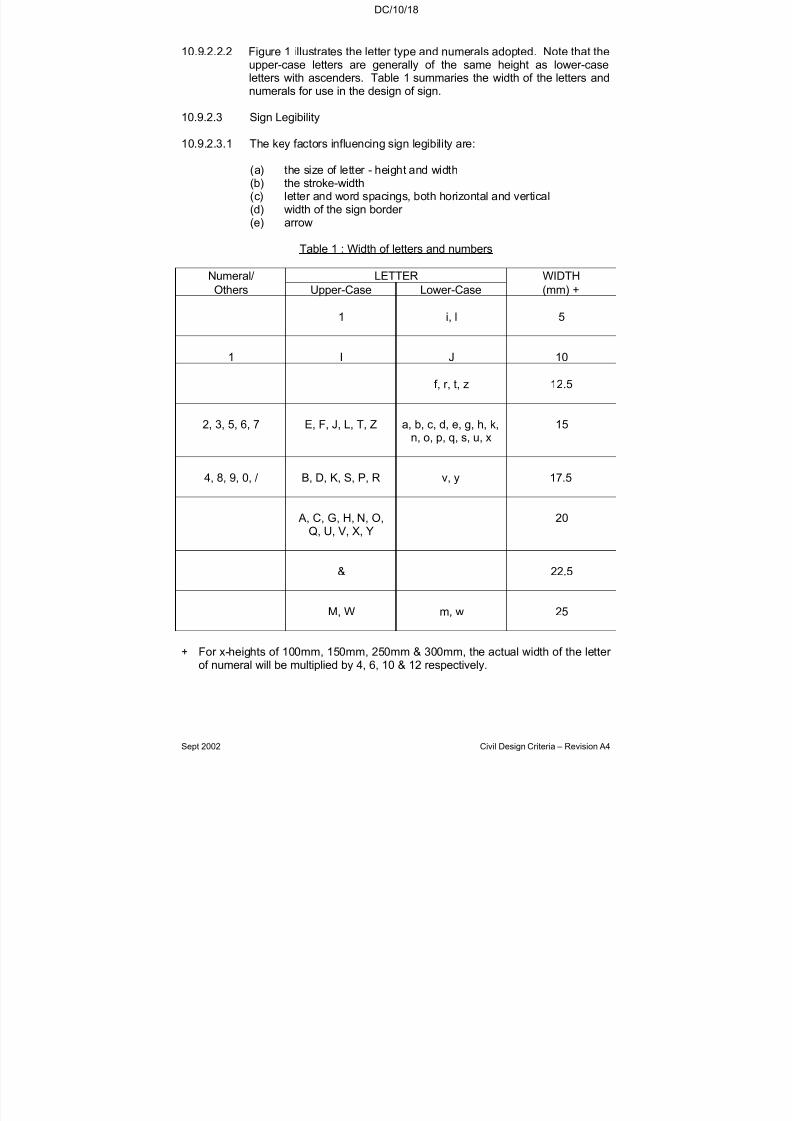
7/18/2019 LTA Civil_standards- Civil Design Criteria
http://slidepdf.com/reader/full/lta-civilstandards-civil-design-criteria 198/345
DC/10/18
Sept 2002 Civil Design Criteria – Revision A4
10.9.2.2.2 Figure 1 illustrates the letter type and numerals adopted. Note that theupper-case letters are generally of the same height as lower-caseletters with ascenders. Table 1 summaries the width of the letters andnumerals for use in the design of sign.
10.9.2.3 Sign Legibility
10.9.2.3.1 The key factors influencing sign legibility are:
(a) the size of letter - height and width(b) the stroke-width(c) letter and word spacings, both horizontal and vertical(d) width of the sign border (e) arrow
Table 1 : Width of letters and numbers
Numeral/ LETTER WIDTH
Others Upper-Case Lower-Case (mm) +
1 i, l 5
1 I J 10
f, r, t, z 12.5
2, 3, 5, 6, 7 E, F, J, L, T, Z a, b, c, d, e, g, h, k,
n, o, p, q, s, u, x
15
4, 8, 9, 0, / B, D, K, S, P, R v, y 17.5
A, C, G, H, N, O,Q, U, V, X, Y
20
& 22.5
M, W m, w 25
+ For x-heights of 100mm, 150mm, 250mm & 300mm, the actual width of the letter of numeral will be multiplied by 4, 6, 10 & 12 respectively.

7/18/2019 LTA Civil_standards- Civil Design Criteria
http://slidepdf.com/reader/full/lta-civilstandards-civil-design-criteria 199/345
DC/10/19
Sept 2002 Civil Design Criteria – Revision A4
10.9.2.3.2 Letter Size
The smaller the letter size, the longer the time required to decipher themessage. The driver is thus forced to avert his eyes from the road for alonger period of time than is desired for safe driving. Hence a valuecalled the “x-height” is specified for the lower-case letters and it isdependent on the category of road on which the sign is installed and
also on the type of Information Signs (i.e. Advanced Directional Signs,Directional Signs, Facility Signs, other Information Signs). The x-heights are 150mm for arterial roads and 100mm for other InformationSigns. The x-height for signs at expressway is 250mm so as toimprove the legibility of signs at expressway. The x-height for gantrysign at expressway will be 300mm. Numerals, however, would be of the same height as the upper-case letters. Upper-case letters are 1.4times the x-height.
In addition, the letter size of confirmatory sign is to be the same as thaton advance directional signs for a given type of road.
10.9.2.3.3 Stroke Width
Stroke width affects legibility of letters. For example, thicker strokewidths require greater spacing between letters because the eye tendsto fuse together individual letters. Normal ratios for height to strokewidth for UK signs range from 5:1 to 9:1. In Singapore, the height tostroke-width ratio for upper-case letters is 7:1 for all alphabets, exceptfor letter Q. For lower-case letters, the range is from 5:1 to 9:1corresponding to x-heights of 100mm, 150mm and 250mm, the stroke-widths are 20mm, 30mm, 50mm and 60mm respectively.
10.9.2.3.4 Letter and Word Spacings
(a) Letter Spacing
Spacing between letters and words is a critical aspect in signdesign, especially so for reflectorised information signs. Itdetermines the maximum legibility distance and allows themessage to be evenly balanced giving the sign panel a pleasingappearance. The following guidelines in Tables 2, 3 and 4 arethe recommended spacing between letters. The recommended
guidelines for spacing between numerals is shown in Table 5.
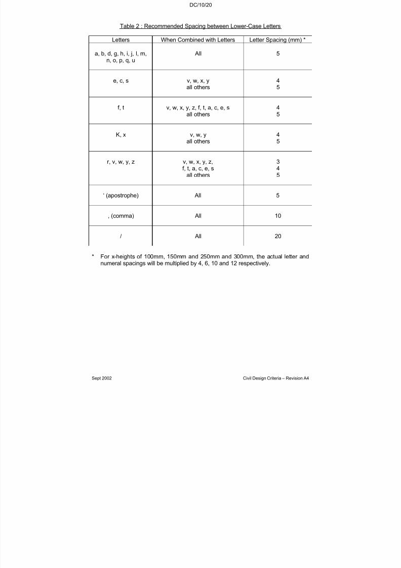
7/18/2019 LTA Civil_standards- Civil Design Criteria
http://slidepdf.com/reader/full/lta-civilstandards-civil-design-criteria 200/345
DC/10/20
Sept 2002 Civil Design Criteria – Revision A4
Table 2 : Recommended Spacing between Lower-Case Letters
Letters When Combined with Letters Letter Spacing (mm) *
a, b, d, g, h, i, j, l, m,n, o, p, q, u
All 5
e, c, s v, w, x, yall others
45
f, t v, w, x, y, z, f, t, a, c, e, sall others
45
K, x v, w, yall others
45
r, v, w, y, z v, w, x, y, z,f, t, a, c, e, s
all others
345
‘ (apostrophe) All 5
, (comma) All 10
/ All 20
* For x-heights of 100mm, 150mm and 250mm and 300mm, the actual letter andnumeral spacings will be multiplied by 4, 6, 10 and 12 respectively.

7/18/2019 LTA Civil_standards- Civil Design Criteria
http://slidepdf.com/reader/full/lta-civilstandards-civil-design-criteria 201/345
DC/10/21
Sept 2002 Civil Design Criteria – Revision A4
Table 3 : Recommended Spacing between Initial Capital and Lower-Case Letters
InitialWhen Combined WithLower-Case Letters
Letter Spacing *(mm)
A, C, E v, wf, t, x, y
all others
34
5
B, D, G, H, I, J, M, N, O,Q, R, S, U
f, t, v, w, x, yall others
45
F, K, P, T, V, W, X, Y, Z v, w, x, yall others
34
L f, t, v, w, x, yall others
34
‘ (apostrophe) All 5
, (comma) All 10
/ All 20
* For x-heights of 100mm, 150mm, 250mm and 300mm, the actual letter and numeral spacings will be multiplied by 4,6,10 and 12 respectively.
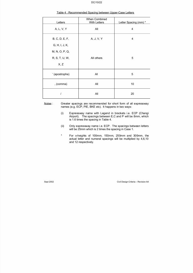
7/18/2019 LTA Civil_standards- Civil Design Criteria
http://slidepdf.com/reader/full/lta-civilstandards-civil-design-criteria 202/345
DC/10/22
Sept 2002 Civil Design Criteria – Revision A4
Table 4 : Recommended Spacing between Upper-Case Letters
LettersWhen Combined
With Letters Letter Spacing (mm) *
A, L, V, Y All 4
B, C, D, E, F,
G, H, I, J, K,
M, N, O, P, Q,
R, S, T, U, W,
X, Z
A, J, V, Y
All others
4
5
‘ (apostrophe) All 5
, (comma) All 10
/ All 20
Notes : Greater spacings are recommended for short form of all expressway
names (e.g. ECP, PIE, BKE etc). It happens in two ways:
(i) Expressway name with Legend in brackets i.e. ECP (Changi Airport). The spacings between E,C and P will be 8mm, whichis 1.6 times the spacing in Table 4.
(ii) Only expressway name i.e. ECP. The spacings between letterswill be 25mm which is 2 times the spacing in Case 1.
* For x-heights of 100mm, 150mm, 250mm and 300mm, theactual letter and numeral spacings will be multiplied by 4,6,10
and 12 respectively.
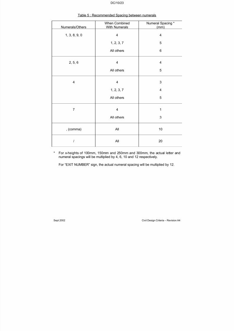
7/18/2019 LTA Civil_standards- Civil Design Criteria
http://slidepdf.com/reader/full/lta-civilstandards-civil-design-criteria 203/345
DC/10/23
Sept 2002 Civil Design Criteria – Revision A4
Table 5 : Recommended Spacing between numerals
Numerals/OthersWhen CombinedWith Numerals
Numeral Spacing *(mm)
1, 3, 8, 9, 0 4
1, 2, 3, 7
All others
4
5
6
2, 5, 6 4
All others
4
5
4 4
1, 2, 3, 7
All others
3
4
5
7 4
All others
1
3
, (comma) All 10
/ All 20
* For x-heights of 100mm, 150mm and 250mm and 300mm, the actual letter andnumeral spacings will be multiplied by 4, 6, 10 and 12 respectively.
For “EXIT NUMBER” sign, the actual numeral spacing will be multiplied by 12.
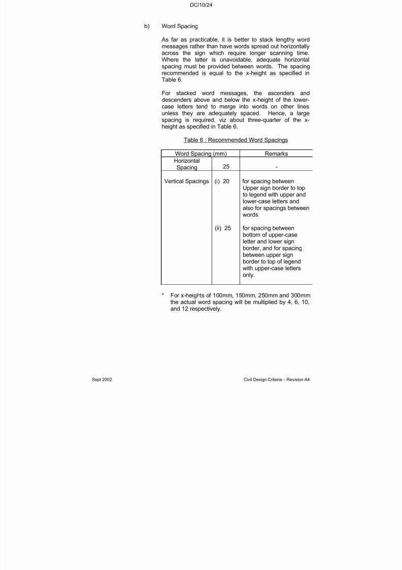
7/18/2019 LTA Civil_standards- Civil Design Criteria
http://slidepdf.com/reader/full/lta-civilstandards-civil-design-criteria 204/345
DC/10/24
Sept 2002 Civil Design Criteria – Revision A4
b) Word Spacing
As far as practicable, it is better to stack lengthy wordmessages rather than have words spread out horizontallyacross the sign which require longer scanning time.Where the latter is unavoidable, adequate horizontalspacing must be provided between words. The spacing
recommended is equal to the x-height as specified inTable 6.
For stacked word messages, the ascenders anddescenders above and below the x-height of the lower-case letters tend to merge into words on other linesunless they are adequately spaced. Hence, a largespacing is required, viz about three-quarter of the x-height as specified in Table 6.
Table 6 : Recommended Word Spacings
Word Spacing (mm) Remarks
HorizontalSpacing 25 -
Vertical Spacings (i) 20 for spacing betweenUpper sign border to topto legend with upper andlower-case letters andalso for spacings betweenwords.
(ii) 25 for spacing betweenbottom of upper-caseletter and lower signborder, and for spacingbetween upper signborder to top of legendwith upper-case lettersonly.
* For x-heights of 100mm, 150mm, 250mm and 300mmthe actual word spacing will be multiplied by 4, 6, 10,and 12 respectively.
7/18/2019 LTA Civil_standards- Civil Design Criteria
http://slidepdf.com/reader/full/lta-civilstandards-civil-design-criteria 205/345
DC/10/25
Sept 2002 Civil Design Criteria – Revision A4
10.9.2.3.5 Width of Sign Borders
The width of sign borders is recommended to be 4mm. This will bemultiplied by 4, 6, 10 and 12 depending on the x-height used.
10.9.2.3.6 Arrows
(a) Arrows are used on information signs to indicate clearly thedirection towards designated routes or destinations shown onthe sign panel. For adequate legibility, the barb width of thearrow should generally be at least equal to the height of thelargest letter on the sign.
(b) Figures 2a and 2b shows the dimensions of the type of arrowused on stack-type messages and rectangular information signs.For x-heights of 100mm, 150mm, 250mm and 300mm the actualarrow size should be multiplied by 4, 6, 10 & 12 respectively.When used as a sloping arrow to indicate turn-offs, the arrow
should be inclined at 55o
to the horizontal as demonstrated inFigure 2b.
(c) An illustration of the recommended layout for a stack-typemessage is shown in Figure 3. It shows the spacing of thearrow within the frame when there is only one row of word(s).
(d) Arrows are also used on flag-type information signs. Their recommended layout and dimensions are shown in Figure 4.Note that the angle subtended by the arrow barb is 120
o.
(e) On gantry signs where it is desired to indicate a lane to befollowed for lane control purposes, the arrow shall be placed onthe sign to point downward towards the centre of that lane. Thearrow type used for this purpose is shown in Figure 5.
10.9.2.4 Sign Jointings & Corners of the Sign-Board
The number of joints in a sign should be kept to a minimum for ease of erection, economic and aesthetic reasons. This will also preventmanufacturers from using scrapped pieces of metal to produce thesign. However, the maximum size of a aluminium plate that can be
taken by the machine is 1.2m by 1.8m. This will govern the minimumnumber of joints for a given size of sign. The drawings submitted to themanufacturer will delineate the positions of the minimum number of
joints consistent with a given size of sign and stipulate that no other joints are to be allowed. In particular, for signs with dimensions smaller than 1.2m by 1.8m, no joints will be permitted in the aluminium plateand the reflective sheeting. The corners of all the sign board shall berounded to a radius of 45mm.

7/18/2019 LTA Civil_standards- Civil Design Criteria
http://slidepdf.com/reader/full/lta-civilstandards-civil-design-criteria 206/345
DC/10/26
Sept 2002 Civil Design Criteria – Revision A4
10.9.2.5 Number of Legends
Preferably, only three legends are to be used, but there shoulddefinitely be not more than four legends on the directional signs.
10.9.2.6 Colour Codes
The existing colour codes are to be retained. However, theexpressway symbol will appear together with the yellow legends,whenever these are shown on the directional sign.
Table 7 : Colour Code
Colour Code
Lettering Arrow& Border Background Remarks
A Yellow Green a) Directional signs(leading to
destinations alongexpressways).
b) Expressway NameSigns.
c) Expressway 1/2kilometer posts.
B White Green a) Directional signs(leading todestinations outside
the expressways).
C Black White a) Facility signs.b) Street Name Signs
D White Blue a) Other informationsigns.
10.9.2.7 Expressway Symbol
(a) Expressway symbol is to be used together with the yellowlegends. The following table shows the size of symbol to beused under different situations. The dimensions of the symbolsdo not include the width of the border which is 10mm for all of them:

7/18/2019 LTA Civil_standards- Civil Design Criteria
http://slidepdf.com/reader/full/lta-civilstandards-civil-design-criteria 207/345
DC/10/27
Sept 2002 Civil Design Criteria – Revision A4
Table 8 : Expressway Symbols
Type of Road or Sign One Legend (mm) Two Legends (mm)
Arterial 280 x 250 385 x 350
Expressway 385 x 350 560 x 500
Gantry 560 x 500 728 x 650
(b) The different sizes of Expressway symbol can be obtained bymultiplying the width and height of the smallest symbol in Figure6 by the following factors.
Table 9 : Multiplying factors for expressway symbols
Size of ExpresswaySymbol (mm) Width Factor Length Factor
385 x 350 1.375(x 280)
1.40(x 250)
560 x 500 2.00 2.00
728 x 650 2.60 2.60
Table 10 : Enlargement Factors For Different Signs
AdvancedDirectional
Signs
DirectionalSigns
Facility &Information
Signs
GantrySigns
Expressway 10 (250) 10 (250) 10 (250) 12 (300)
Major Arterials& Collectors
6 (150) 6 (150) 6 *(150) 12 #(300)10 (250)
Minor Roads 4 (100) 4 (100) 4 (100) 12 #(300)10 (250)

7/18/2019 LTA Civil_standards- Civil Design Criteria
http://slidepdf.com/reader/full/lta-civilstandards-civil-design-criteria 208/345
DC/10/28
Sept 2002 Civil Design Criteria – Revision A4
Notes:
(i) * Factor 6 is used if the sign is mounted with one or moredirectional signs on the frame. If on its own, factor 4 isrecommended.
(ii). ( ) Figures in bracket are the x-heights of the actual sizes of
characters.
(iii) # Factor 12 is preferred if space on the gantry sign permits.
10.9.2.8 Expressway numbering system and the arrangement of signs
(a) The expressway number is the same as the number of thekilometre post closest to the expressway exit with the necessarysuffix letter “A” or “B” to denote exits to different directions. Theexit number for each exit is repeated two times; one of them is
on the intermediate sign at the nose. Figure 7 and Figure 8illustrates the arrangement of the signs.
(b) For “EXIT NUMBER” sign (e.g Figures 9 and 10), the height of the word “EXIT” is 210 mm and that of the number/alphabet is420mm having a multiplying factor of 6 and 12 respectively toletters & numerals shown in Figure 1. Table 5 should bereferred to for spacing between numerals.
(c) Note that the spacing between the word “EXIT” and the“number” is 200mm. The horizontal spacings on both sides to
sign borders are 220mm and the vertical spacings are 150mmfor both top and bottom to the sign border. Above arrangementshould be used for all “EXIT NUMBER” sign. Wider horizontalspacing is used at the intermediate sign between “EXIT” and the“number” which is 300mm (Figure 11).
10.9.3 Siting of Signs
On expressways, the intermediate directional sign with exit number andadvance directional sign are to be located respectively at 300m and600m away from the chevron marking of the traffic island separating
through and diverging or turning traffic. The exit distance sign(incorporated at directional signs) shown in Figure 12 and the exitdistance sign (attached to directional sign) shown in Figure 13 are to beused. One advance directional sign is located 150m before theintersection would suffice for major arterial roads, an extra advancedirectional sign sited at 300m before the intersection is accepted. Theconfirmatory sign for both major arterial roads and expressways shouldbe located at the nose of the traffic island separating through andturning traffic.

7/18/2019 LTA Civil_standards- Civil Design Criteria
http://slidepdf.com/reader/full/lta-civilstandards-civil-design-criteria 209/345
DC/10/29
Sept 2002 Civil Design Criteria – Revision A4
10.9.4 Materials for Sign
Aluminium sheeting of thickness No. 14SWG is to be used inmanufacturing the signs. Diamond grade reflective sheetings are usedfor background, letters, arrows, borders and expressway symbol.
10.9.5 Sign Support
10.9.5.1 Details of support for directional and informatory signs are shown inStandard Details of Road Elements.
10.9.5.2 Manufacturers are required to engraved/etched the “date of manufacture” (ie Nov/97 or 11/97) at the back of the sign plate.
10.9.6 Blockage of Signs by trees
On expressways, trees within 75m in front of the advance directionalsign are to be replaced by low shrubs or hedges. On major arterial
roads, the corresponding distance is 45m.
10.9.7 Other Examples
Other examples showing typical arrangements of directional sign areillustrated in Figures 14, 15, 16, 17, 18, 19, 20, 21, 22, and 23.
10.10 SITING OF INFORMATION SIGNS
10.10.1 Advance Directional and Directional signs shall generally be sited on
the driver’s off-side. Minimum lateral clearance distances from theedge of the road kerb to any part of the sign are 500mm where raisedkerbs are used and 750 mm where flush kerbs with hard shoulders areused.
10.10.2 Directional signs shall be appropriately sited to clearly point to the routedisplayed by the signs. Similar requirements for lateral clearance asthose for the Advance Directional Signs shall be observed. Care shallbe exercised not to locate signs as to adversely affect the drivers’visibility.
10.10.3 To avoid direct reflection from headlamp beams, signs shall be sited at950 away from the line of a straight carriageway. For left hand bends,the 950 angle shall be measured from a line joining the sign to a pointat the edge of the carriageway and 180m before the sign.
10.10.4 The design of the signs shall also include the design of posts andbraces necessary to support the signs. Authority’s Standard Details of Road Elements may be used as a guide. 3M High Intensity GradeReflective Film, or approved equivalents, on 14G aluminium sheetingshall be used. This backing aluminium sheeting shall be in one pieceas far as practicable. Any joints in the backing plate shall have the

7/18/2019 LTA Civil_standards- Civil Design Criteria
http://slidepdf.com/reader/full/lta-civilstandards-civil-design-criteria 210/345
DC/10/30
Sept 2002 Civil Design Criteria – Revision A4
prior written approval of the Engineer. Where rivets are used in thefabrication of these signs, they shall be of the countersunk type andshall leave no discernible marking on the reflective surface of the sign.

7/18/2019 LTA Civil_standards- Civil Design Criteria
http://slidepdf.com/reader/full/lta-civilstandards-civil-design-criteria 211/345
DC/10/31
Sept 2002 Civil Design Criteria – Revision A4
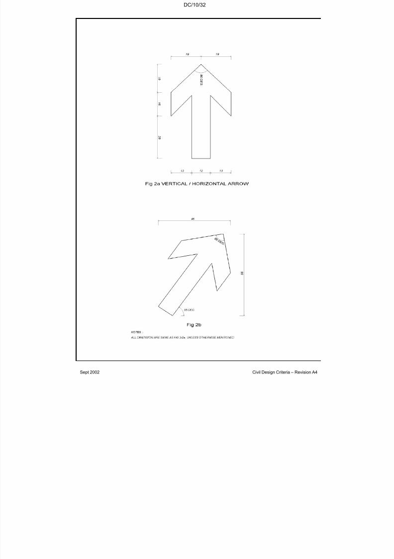
7/18/2019 LTA Civil_standards- Civil Design Criteria
http://slidepdf.com/reader/full/lta-civilstandards-civil-design-criteria 212/345
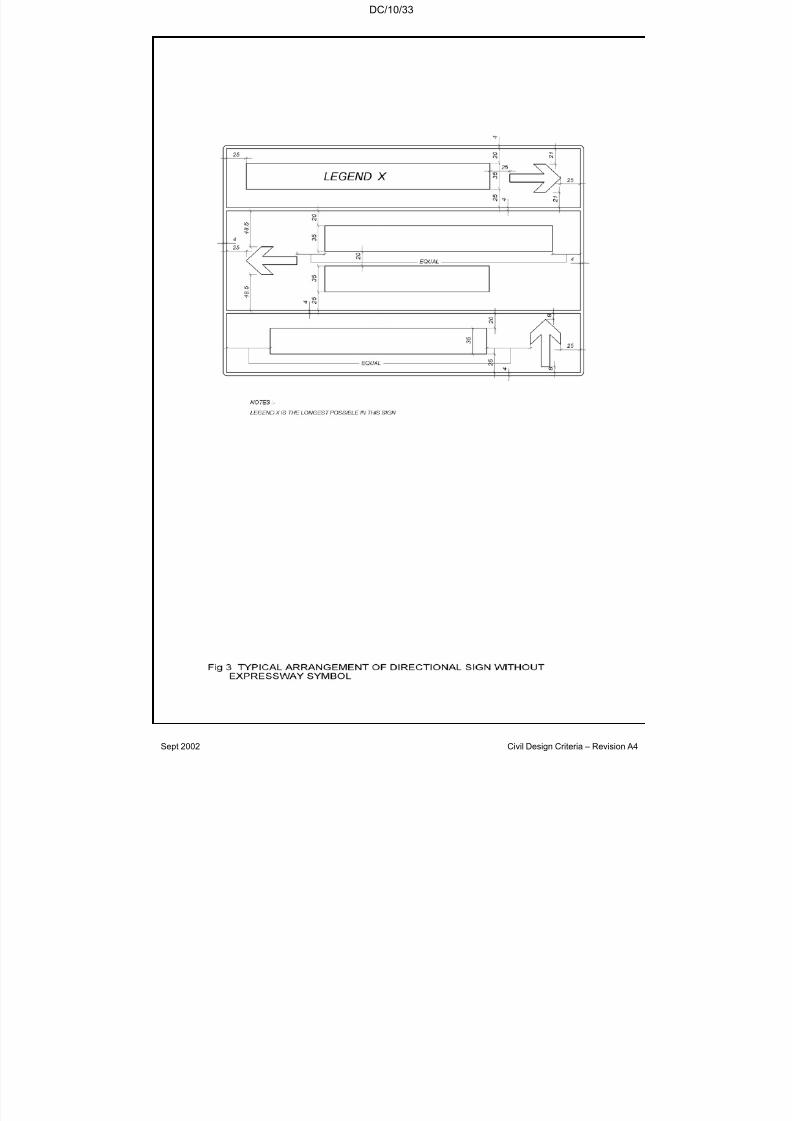
7/18/2019 LTA Civil_standards- Civil Design Criteria
http://slidepdf.com/reader/full/lta-civilstandards-civil-design-criteria 213/345
DC/10/33
Sept 2002 Civil Design Criteria – Revision A4

7/18/2019 LTA Civil_standards- Civil Design Criteria
http://slidepdf.com/reader/full/lta-civilstandards-civil-design-criteria 214/345
DC/10/34
Sept 2002 Civil Design Criteria – Revision A4
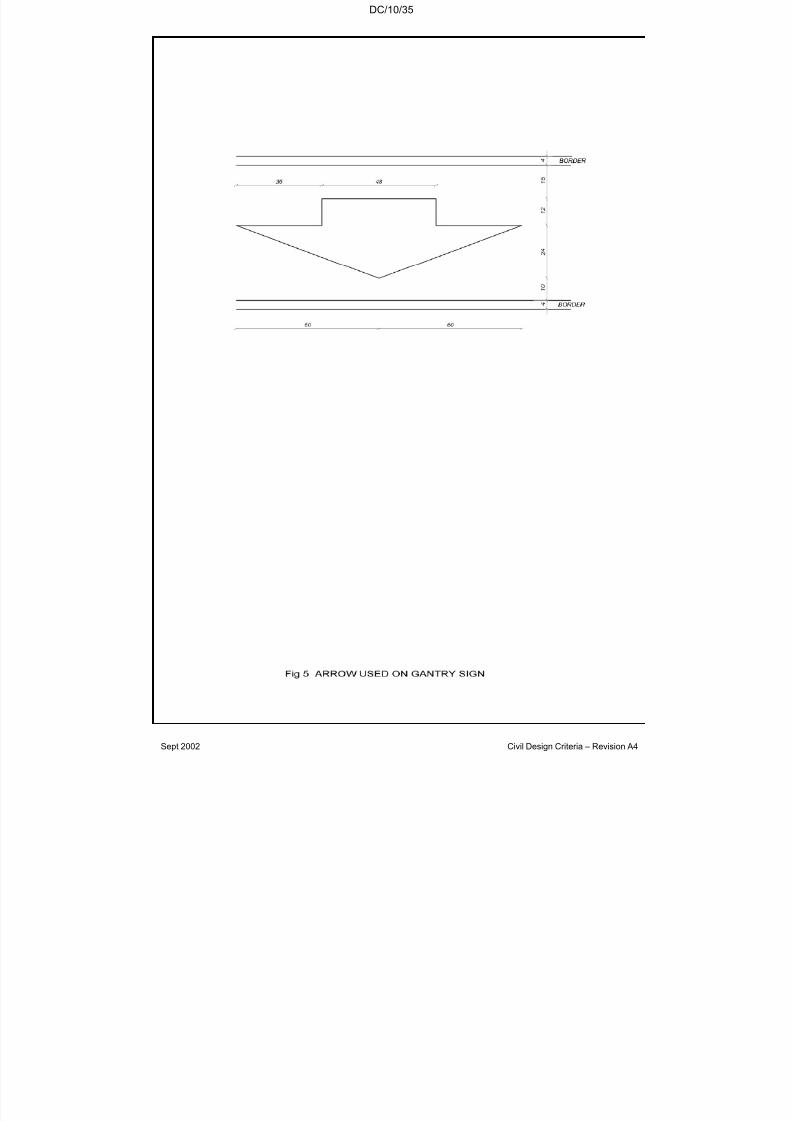
7/18/2019 LTA Civil_standards- Civil Design Criteria
http://slidepdf.com/reader/full/lta-civilstandards-civil-design-criteria 215/345
DC/10/35
Sept 2002 Civil Design Criteria – Revision A4

7/18/2019 LTA Civil_standards- Civil Design Criteria
http://slidepdf.com/reader/full/lta-civilstandards-civil-design-criteria 216/345
DC/10/36
Sept 2002 Civil Design Criteria – Revision A4
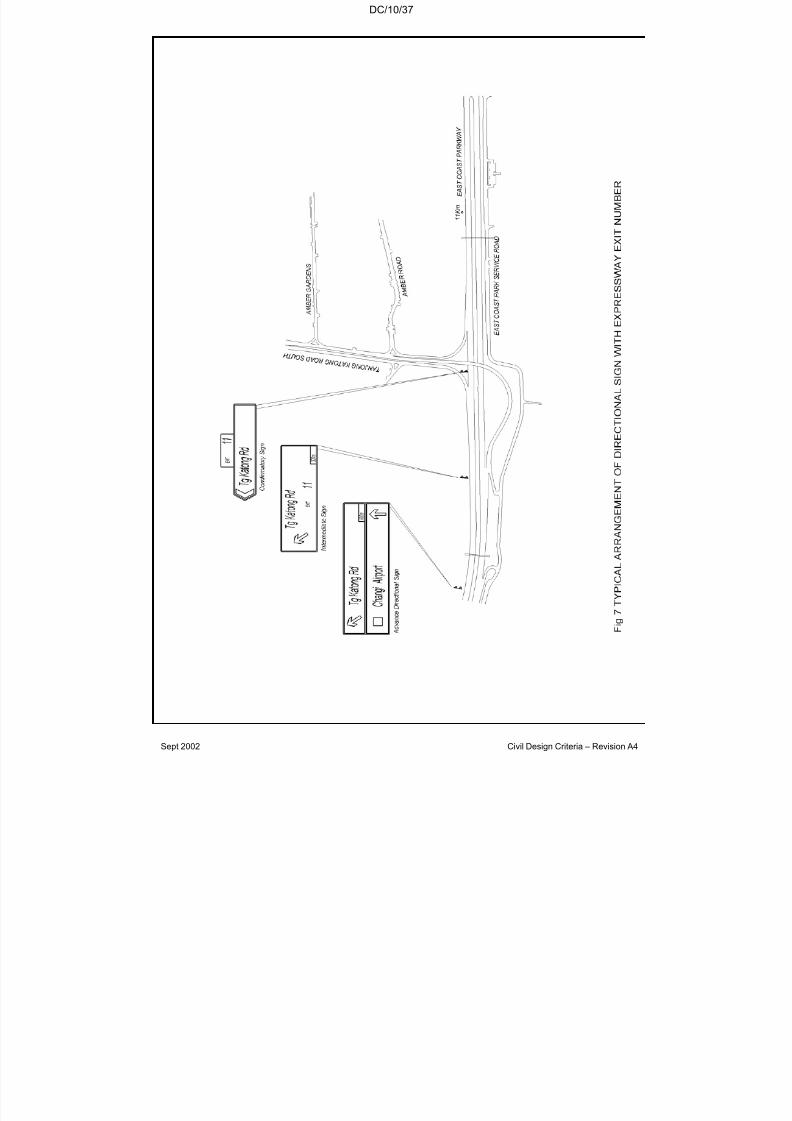
7/18/2019 LTA Civil_standards- Civil Design Criteria
http://slidepdf.com/reader/full/lta-civilstandards-civil-design-criteria 217/345
DC/10/37
Sept 2002 Civil Design Criteria – Revision A4
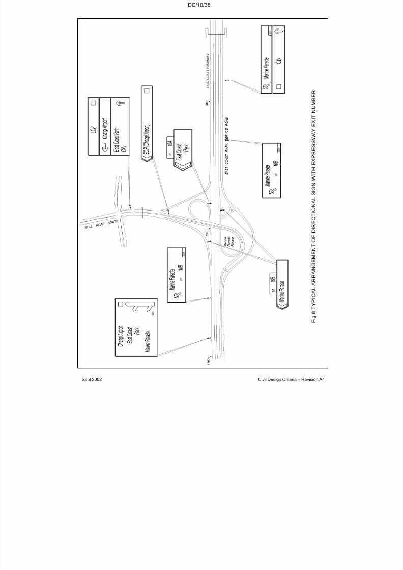
7/18/2019 LTA Civil_standards- Civil Design Criteria
http://slidepdf.com/reader/full/lta-civilstandards-civil-design-criteria 218/345
DC/10/38
Sept 2002 Civil Design Criteria – Revision A4

7/18/2019 LTA Civil_standards- Civil Design Criteria
http://slidepdf.com/reader/full/lta-civilstandards-civil-design-criteria 219/345
DC/10/39
Sept 2002 Civil Design Criteria – Revision A4
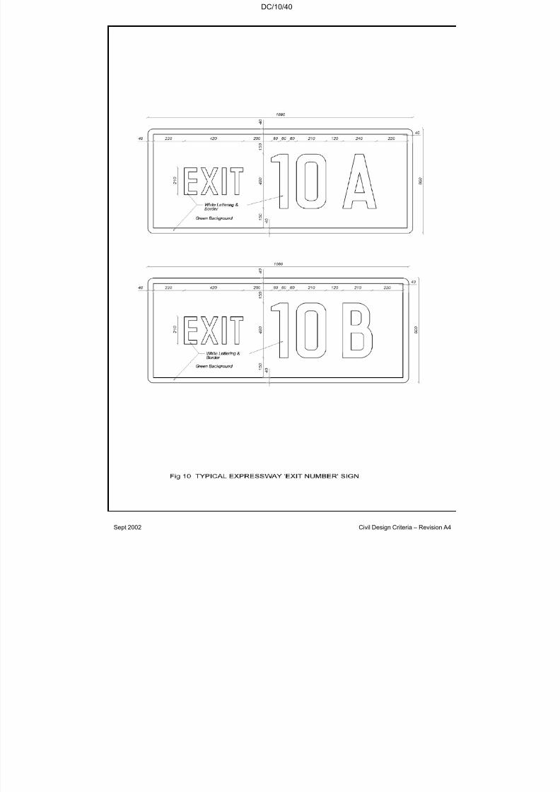
7/18/2019 LTA Civil_standards- Civil Design Criteria
http://slidepdf.com/reader/full/lta-civilstandards-civil-design-criteria 220/345
DC/10/40
Sept 2002 Civil Design Criteria – Revision A4

7/18/2019 LTA Civil_standards- Civil Design Criteria
http://slidepdf.com/reader/full/lta-civilstandards-civil-design-criteria 221/345
DC/10/41
Sept 2002 Civil Design Criteria – Revision A4
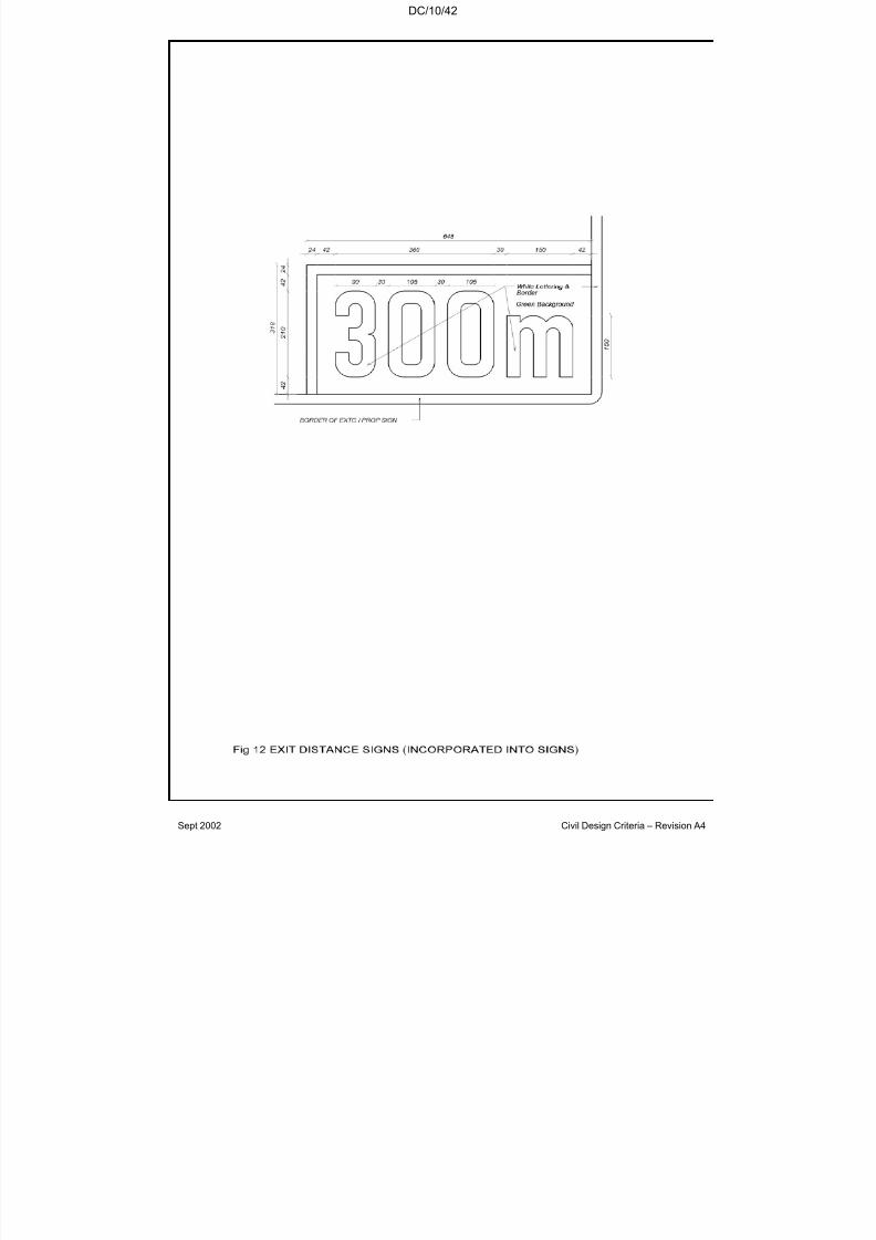
7/18/2019 LTA Civil_standards- Civil Design Criteria
http://slidepdf.com/reader/full/lta-civilstandards-civil-design-criteria 222/345
DC/10/42
Sept 2002 Civil Design Criteria – Revision A4

7/18/2019 LTA Civil_standards- Civil Design Criteria
http://slidepdf.com/reader/full/lta-civilstandards-civil-design-criteria 223/345
DC/10/43
Sept 2002 Civil Design Criteria – Revision A4

7/18/2019 LTA Civil_standards- Civil Design Criteria
http://slidepdf.com/reader/full/lta-civilstandards-civil-design-criteria 224/345
DC/10/44
Sept 2002 Civil Design Criteria – Revision A4

7/18/2019 LTA Civil_standards- Civil Design Criteria
http://slidepdf.com/reader/full/lta-civilstandards-civil-design-criteria 225/345
DC/10/45
Sept 2002 Civil Design Criteria – Revision A4

7/18/2019 LTA Civil_standards- Civil Design Criteria
http://slidepdf.com/reader/full/lta-civilstandards-civil-design-criteria 226/345
DC/10/46
Sept 2002 Civil Design Criteria – Revision A4
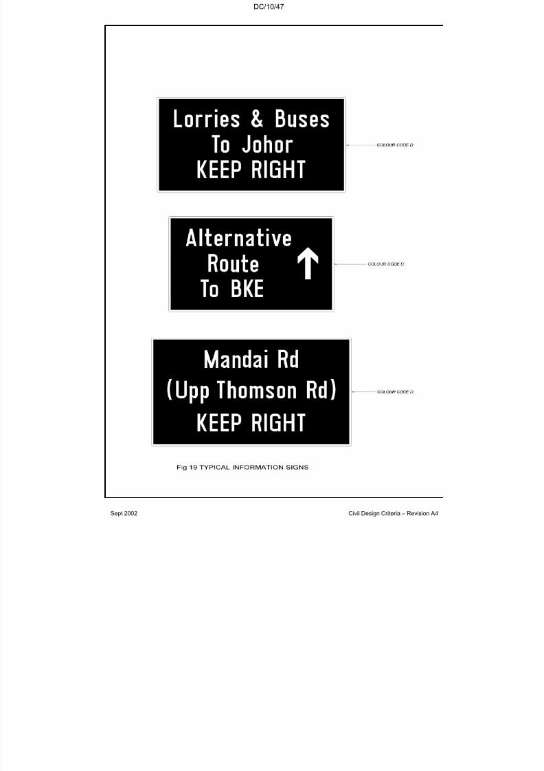
7/18/2019 LTA Civil_standards- Civil Design Criteria
http://slidepdf.com/reader/full/lta-civilstandards-civil-design-criteria 227/345
DC/10/47
Sept 2002 Civil Design Criteria – Revision A4

7/18/2019 LTA Civil_standards- Civil Design Criteria
http://slidepdf.com/reader/full/lta-civilstandards-civil-design-criteria 228/345
DC/10/48
Sept 2002 Civil Design Criteria – Revision A4

7/18/2019 LTA Civil_standards- Civil Design Criteria
http://slidepdf.com/reader/full/lta-civilstandards-civil-design-criteria 229/345
DC/10/49
Sept 2002 Civil Design Criteria – Revision A4
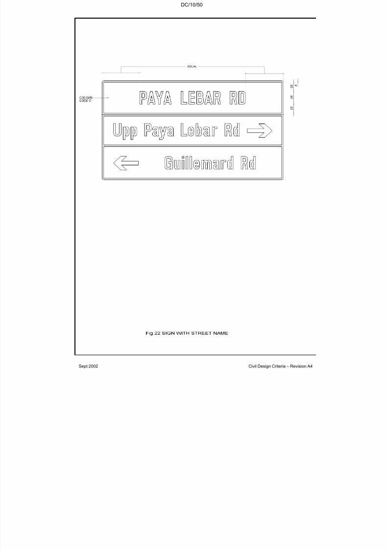
7/18/2019 LTA Civil_standards- Civil Design Criteria
http://slidepdf.com/reader/full/lta-civilstandards-civil-design-criteria 230/345
DC/10/50
Sept 2002 Civil Design Criteria – Revision A4

7/18/2019 LTA Civil_standards- Civil Design Criteria
http://slidepdf.com/reader/full/lta-civilstandards-civil-design-criteria 231/345
DC/10/51
Sept 2002 Civil Design Criteria – Revision A4
7/18/2019 LTA Civil_standards- Civil Design Criteria
http://slidepdf.com/reader/full/lta-civilstandards-civil-design-criteria 232/345
DC/11/1
Sept 2002 Civil Design Criteria – Revision A4
CHAPTER 11
STATION AND TUNNEL SERVICES FOR RAIL PROJECTS
11.1 GENERAL REQUIREMENTS
11.1.1 Standard Codes and Regulations
The design of Station and Tunnel Services for Rail Projects shall begoverned by all latest applicable local codes, regulations, standardsand requirements issued by all the local Authorities and StatutoryBoards including but not limited to: -
(1) Fire Safety Bureau (FSB)
(2) Public Utilities Board (PUB)
(3) Land Transport Authority (LTA)
(4) Ministry of the Environment (ENV)
(5) Singapore Productivity and Standards Board (PSB)
11.1.2 Approvals
The Contractor shall be responsible for the submission of BuildingPlans and other details to the relevant government authorities andStatutory Boards and for obtaining the full clearance for the variousservices systems.
11.1.3 Routing of Pipework and Services
Pipework shall comply with the requirements for Water and Electricalequipment in Chapter 13. Pipework, services and fittings shall berouted so as to accommodate future maintenance. As far aspracticable, they shall not be located above escalators or voids.
11.2 DRAINAGE
11.2.1 General
11.2.1.1 All internal surfaces of structures shall be positively drained viachannels, drains etc., either by gravity to existing storm water drainageor to wet sumps from where water shall be pumped to the storm water drainage, all to the approval of the appropriate Authorities and StatutoryBoards and to the acceptance of the Engineer.

7/18/2019 LTA Civil_standards- Civil Design Criteria
http://slidepdf.com/reader/full/lta-civilstandards-civil-design-criteria 233/345
DC/11/2
Sept 2002 Civil Design Criteria – Revision A4
11.2.1.2 Separate drainage systems shall be provided for each of the following:
1) TUNNEL DRAINAGE.
This system shall deal with water originating from:
• ground water seepage
• tunnel condensation
• tunnel washing
• testing and emptying of the fire mains
• condensate from train air-conditioning
• rain water blown into the tunnel or brought into tunnel by wetrolling stock.
2) STATION DRAINAGE.
This system shall deal with water originating from:
• groundwater seepage
• tunnel condensation
• tunnel washing
• testing and emptying of the fire mains
• condensate from train air-conditioning
• condensate from ECS associated plants
• water tank overflow and drainage
• all clean water in the station
• all clean water brought into station
(3) STORM W ATER DRAINAGE.
This system shall deal with all rainwater falling on the station roofs andexternal areas to be directed into the existing storm water drainagesystem.
11.2.2 Tunnel Drainage
11.2.2.1 Seepage
Drainage design shall be based on permitted seepage values given inSection 7.5.3. All water shall be directed so that the rails and rail fixingsremain dry.
7/18/2019 LTA Civil_standards- Civil Design Criteria
http://slidepdf.com/reader/full/lta-civilstandards-civil-design-criteria 234/345
DC/11/3
Sept 2002 Civil Design Criteria – Revision A4
11.2.2.2 Tunnel Washing
The design shall allow for tunnel washing during the 6 hour period from0000hrs to 0600hrs. The maximum storage capacity of the TrackCleaning Vehicle is 18,000 litres. The maximum discharge rate will be10,800 litres/hr and shall be allowed for in the design of any tunnelpump sump.
11.2.2.3 Fire Main
The volume of water discharged during testing and emptying of the firemain shall be determined in co-ordination with the System-wideContractor and allowed for in the design of the tunnel pump sump.
11.2.2.4 Condensate From Train Air-Conditioning
Condensate from moving trains may be assumed to be evaporated.
11.2.2.5 Tunnel Pump Sump
11.2.2.5.1 Location
A pump sump shall be located at every low point within each runningtunnel. If the pump sump location coincides with a cross passage, thenonly one pump sump shall be provided and it shall be located in thecross passage.
11.2.2.5.2 Details
Provisions and layout of the pump sump shall follow that for the stationas described in Section 11.2.4.
The discharge pipes from the tunnel sump pumps shall be routeddirectly to the surface drains via the nearest station, vent shaft, escapeshaft or service shaft/duct. The water shall not be discharged toanother drainage pumping system within the Works. Swan necks shallbe provided at the appropriate locations. Flap valves shall be providedat the discharge ends. Discharge pipe shall have a minimum diameter of 100mm. Velocity of water in discharge pipes shall be between 1m/sand 2.4m/s to ensure self cleansing and prevent scouring.
Tunnel drainage sumps shall be monitored at the nearest station.
11.2.2.5.3 Design and Construction
The design of the tunnel sumps and the pumps shall be in accordancewith Section 11.2.5.
The structural design of sumps shall comply to requirements inChapters 7 & 8 with the sumps regarded as an underground structure.
7/18/2019 LTA Civil_standards- Civil Design Criteria
http://slidepdf.com/reader/full/lta-civilstandards-civil-design-criteria 235/345
DC/11/4
Sept 2002 Civil Design Criteria – Revision A4
11.2.3 Station Drainage
General requirements are summarised in Table 11.1. All outlets shallbe discharged to the drainage system unless stated otherwise in thespecifications. The Drainage System shall incorporate theserequirements and shall be designed in accordance with Section 11.2.5.Design of Station Drainage systems shall comply with all requirements
that may be imposed by the Central Building Plan Unit of the Ministry of Environment.
TABLE 11.1
DRAINAGE SYSTEM PROVISION IN STATIONS
Room/Area Requirement Remarks
1. Seepage channel Floor wastesat 10m max.interval
See Section 11.2.3.1.
2. Escalator pit One floor waste per pit See Section 11.2.3.2.
3. Vent Shaft/Duct Floor waste See Section 11.2.3.3.
4. Underplatform Areas
Channels, floor wastes See Section 11.2.3.5
5. All ECS associatedPlant Rooms
One floor waste Adjacent to AHU for condensation water. SeeSection 11.2.3.6.
6. Lift pit Floor waste See Section 11.2.3.7
7. Entrance stair Floor waste per entrance See Section 11.2.3.88. Cable Trench,
Valve Chamber &Maintenance Pits*
Floor waste See Section 11.2.3.9
9. All water tank/pumproom
One sump with floor waste
For draining of tank water and overflow. See Section11.2.3.4
10. Adjacent tohosereels
One floor waste For accidental spillage of water or fire fighting water.Drainage via seepage
channel outlets is notallowed.
11. All enclosedstaircases (atlowest landing)
One floor waste For accidental spillage of water or fire fighting water.
7/18/2019 LTA Civil_standards- Civil Design Criteria
http://slidepdf.com/reader/full/lta-civilstandards-civil-design-criteria 236/345
DC/11/5
Sept 2002 Civil Design Criteria – Revision A4
TABLE 11.1 (Cont’d)
DRAINAGE SYSTEM PROVISION IN STATIONS
Room/Area Requirement Remarks
12. Elevated and exposed
platforms (elevatedstation)
Two parallel channels run
along the track directionfor each platform, withappropriate connection tothe drainage system.
For rain water blown onto
the platform plus washingwater.
13. Planter in station (a) Floor waste Hydroponic plantingdischarge via a silt trap.
(b) Surface drain For ordinary planter.
* These are civil defence facilities in CD stations.
11.2.3.1 Seepage
11.2.3.1.1 Seepage drainage channels shall be provided at the floor level alongthe internal sides of all earth-backed external walls. A drainage channelof 100 mm diameter shall be formed and laid to fall to not less than 1 in200. Discharge outlets (floor drain/trap) of not less than 100 mmdiameter shall be situated at not more than 10m centres.
11.2.3.1.2 Seepage drainage channels shall be lined with a suitable waterproofingmembrane. Drainage channels, weepholes and outlets shall not passthrough fire rated compartment wall.
11.2.3.1.3 Seepage drainage channels in floor finishes shall be at least 35 mmdeep. A cavity of limited height shall be constructed to contain thedrainage at the bottom of the wall if sufficient depth is not available inany floor finish.
11.2.3.1.4 Cavity Walls
11.2.3.1.4.1 For the purpose of establishing cavity wall requirements arecategorised as described below, and as listed in Table 11.2. For anyrooms not listed therein, proposals shall be submitted and agreed withthe Engineer. Where required in any given rooms/areas, cavity walls
need be provided only along the external walls.
(1) Category I
Generally, these are rooms/areas containing sensitive E&M equipmentrequiring extra protection from damp and moisture. Full height cavitywalls shall be provided.
In addition, in rooms/areas that are accessible to the public, full heightcavity walls shall also be provided to protect the architectural finishesfrom seepage water.
7/18/2019 LTA Civil_standards- Civil Design Criteria
http://slidepdf.com/reader/full/lta-civilstandards-civil-design-criteria 237/345
DC/11/6
Sept 2002 Civil Design Criteria – Revision A4
(2) Category II
These are rooms/areas without an immediate need for cavity walls butwhich requires provision for installation of such walls in the future.
Ample space shall be provided in these rooms/areas for future cavitywall construction and the sizing of the rooms shall take this intoaccount. All services/equipment mounted onto the earth backed wall in
such rooms/areas shall be designed such that it can be easily removedand mounted onto a cavity wall should the need arise. Ceiling servicesshall also be such that it will not obstruct the future construction of thecavity wall.
(3) Category III
Cavity wall is not required.
11.2.3.1.4.2 Full height cavity walls shall be constructed as an inner lining with aseepage drainage channel confined to inside the cavity. Access panels
of minimum 600 mm x 600 mm size placed at intervals not exceeding12 metres shall be provided on the cavity walls to permit inspection andmaintenance of the drainage system.
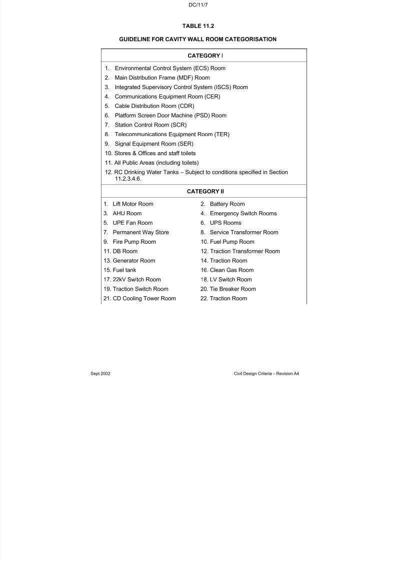
7/18/2019 LTA Civil_standards- Civil Design Criteria
http://slidepdf.com/reader/full/lta-civilstandards-civil-design-criteria 238/345
DC/11/7
Sept 2002 Civil Design Criteria – Revision A4
TABLE 11.2
GUIDELINE FOR CAVITY WALL ROOM CATEGORISATION
CATEGORY I
1. Environmental Control System (ECS) Room
2. Main Distribution Frame (MDF) Room
3. Integrated Supervisory Control System (ISCS) Room
4. Communications Equipment Room (CER)
5. Cable Distribution Room (CDR)
6. Platform Screen Door Machine (PSD) Room
7. Station Control Room (SCR)
8. Telecommunications Equipment Room (TER)
9. Signal Equipment Room (SER)10. Stores & Offices and staff toilets
11. All Public Areas (including toilets)
12. RC Drinking Water Tanks – Subject to conditions specified in Section11.2.3.4.6.
CATEGORY II
1. Lift Motor Room 2. Battery Room
3. AHU Room 4. Emergency Switch Rooms
5. UPE Fan Room 6. UPS Rooms
7. Permanent Way Store 8. Service Transformer Room
9. Fire Pump Room 10. Fuel Pump Room
11. DB Room 12. Traction Transformer Room
13. Generator Room 14. Traction Room
15. Fuel tank 16. Clean Gas Room
17. 22kV Switch Room 18. LV Switch Room
19. Traction Switch Room 20. Tie Breaker Room21. CD Cooling Tower Room 22. Traction Room
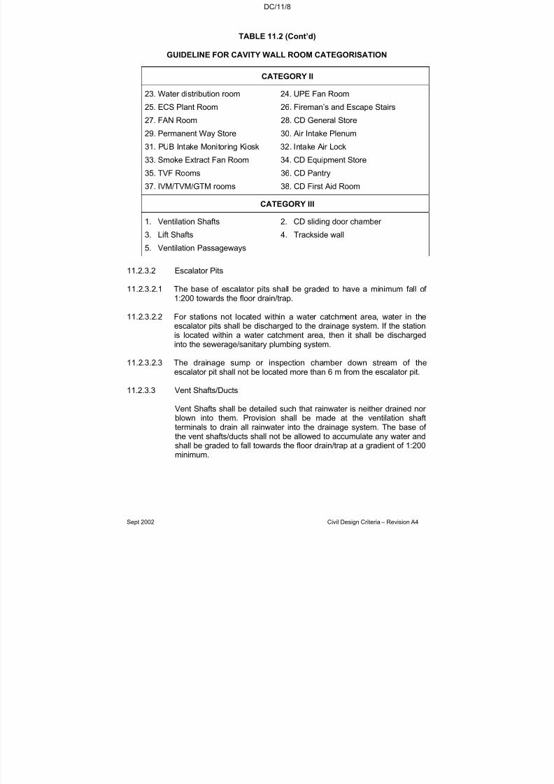
7/18/2019 LTA Civil_standards- Civil Design Criteria
http://slidepdf.com/reader/full/lta-civilstandards-civil-design-criteria 239/345
DC/11/8
Sept 2002 Civil Design Criteria – Revision A4
TABLE 11.2 (Cont’d)
GUIDELINE FOR CAVITY WALL ROOM CATEGORISATION
CATEGORY II
23. Water distribution room 24. UPE Fan Room
25. ECS Plant Room 26. Fireman’s and Escape Stairs
27. FAN Room 28. CD General Store
29. Permanent Way Store 30. Air Intake Plenum
31. PUB Intake Monitoring Kiosk 32. Intake Air Lock
33. Smoke Extract Fan Room 34. CD Equipment Store
35. TVF Rooms 36. CD Pantry
37. IVM/TVM/GTM rooms 38. CD First Aid Room
CATEGORY III
1. Ventilation Shafts 2. CD sliding door chamber
3. Lift Shafts 4. Trackside wall
5. Ventilation Passageways
11.2.3.2 Escalator Pits
11.2.3.2.1 The base of escalator pits shall be graded to have a minimum fall of 1:200 towards the floor drain/trap.
11.2.3.2.2 For stations not located within a water catchment area, water in theescalator pits shall be discharged to the drainage system. If the stationis located within a water catchment area, then it shall be dischargedinto the sewerage/sanitary plumbing system.
11.2.3.2.3 The drainage sump or inspection chamber down stream of theescalator pit shall not be located more than 6 m from the escalator pit.
11.2.3.3 Vent Shafts/Ducts
Vent Shafts shall be detailed such that rainwater is neither drained nor blown into them. Provision shall be made at the ventilation shaftterminals to drain all rainwater into the drainage system. The base of the vent shafts/ducts shall not be allowed to accumulate any water andshall be graded to fall towards the floor drain/trap at a gradient of 1:200minimum.

7/18/2019 LTA Civil_standards- Civil Design Criteria
http://slidepdf.com/reader/full/lta-civilstandards-civil-design-criteria 240/345
DC/11/9
Sept 2002 Civil Design Criteria – Revision A4
11.2.3.4 Water Storage Tanks
11.2.3.4.1 The storage capacity of a water tank is the volume of water that can bedrawn by the water booster/transfer pumps. Water tanks shall bedesigned to minimise dead water volume.
11.2.3.4.2 The inlet and outlet pipes of the tank shall be located to avoid
stagnation of water in the tank.
11.2.3.4.3 The base of the water tank shall have a minimum fall of 1:200 towardsa 200mm minimum diameter drain-off pipe with puddle flange. Thisshall be installed at the base of the water storage tank to drain thewater storage tank completely.
11.2.3.4.4 Overflow pipes for water storage tanks of RC construction shall also beprovided with puddle flanges in accordance with PUB (Water Dept)’srequirements.
11.2.3.4.5 Overflow and drain-off water from storage water tanks shall not bedischarged into the seepage channels directly. They shall bedischarged directly to either a drainage sump or a pump sump.
11.2.3.4.6 R.C. Drinking Water Tanks
RC water tanks for drinking water shall not be in direct contact with soil.No part of the earth-backed RC wall/slab shall form the drinking water tank unless the concrete is designed and constructed in accordancewith the relevant recommendations in SS CP 73. Where this is notpossible, a cavity of minimum 100 mm with seepage channels shall be
provided between the water tank and the earth-backed wall/slab toprevent contamination from any source. Floor drain/trap for theseepage channel shall not exceed 10m intervals. Sufficient provisionsfor future maintenance of the seepage channel and floor drain/trapshall also be provided. RC Water Tanks shall designed in accordancewith SS CP 73 and shall allow for the overflow/outlet pipe beingblocked.
11.2.3.5 Underplatform Areas
Drainage channels of minimum width 100mm shall be provided in the
underplatform areas with a minimum gradient of 1:200. Dischargeoutlets (floor drain/trap) of not less than 100 mm diameter shall besituated at not more than 10m centres. The floor finish of theunderplatform areas shall be made to fall towards these channels.
11.2.3.6 Condensate Drainage
11.2.3.6.1 Drainage is required for condensate water from all ECS associatedsystems (e.g., AHU Plant Room, ECS Plant Room etc.) including air conditioning from trains, ancillary and commercial areas. All

7/18/2019 LTA Civil_standards- Civil Design Criteria
http://slidepdf.com/reader/full/lta-civilstandards-civil-design-criteria 241/345
DC/11/10
Sept 2002 Civil Design Criteria – Revision A4
condensate water shall discharge to the drainage system unless statedotherwise in Section 11.3.
11.2.3.6.2 The location of the condensate points and volume of discharge shall bedetermined through co-ordination with the system-wide contractor.Floor trap being provided shall not be used for discharging water usedfor the cleaning of ECS equipment.
11.2.3.6.3 Any exposed condensate drain/pipe (including floor trap) beneath thesuspended floor slab shall be insulated to prevent condensation.
11.2.3.7 Lift Pit
The base of lift pit shall be graded to have a minimum fall of 1:200towards the floor drain/trap.
11.2.3.8 Entrances
A cut off drain shall be provided across each entrance, at the top of thestairway and escalator. The collected water shall be discharged to thenearest surface drain. The structural recess for the cut off drain shallbe 240mm wide with a minimum depth of 200mm deep, covered with astainless steel grating. A catch pit shall be provided at the drain outlet,or as close thereto as can be arranged, to prevent debris from enteringthe drainage run. Where pipes pass through the joints between thestation structure and the entrance, they shall be detailed toaccommodate all movements.
The minimum platform level and crest protection level for all entrances,
exits, linkages etc. shall be in accordance with PUB’s latestrequirements.
11.2.3.9 Cable Trenches, Valve Chambers and Maintenance Pits
The top of the cable trenches, valve chambers and maintenance pitsshall be made to fall away to prevent water from flowing inside. Thefloors of cable trenches, valve chambers and maintenance pits shall begraded to have a minimum gradient of 1:200 towards the floor drain/trap.
11.2.3.10 Movement Joints
Structural movement joints are highly susceptible to water leakage andadequate provisions for the collection and discharge of all water leakage shall be provided.
11.2.3.11 Dry Sump
A dry sump is a drainage sump without any outlet. Dry sumps shall notbe provided unless accepted by the Engineer.

7/18/2019 LTA Civil_standards- Civil Design Criteria
http://slidepdf.com/reader/full/lta-civilstandards-civil-design-criteria 242/345

7/18/2019 LTA Civil_standards- Civil Design Criteria
http://slidepdf.com/reader/full/lta-civilstandards-civil-design-criteria 243/345
DC/11/12
Sept 2002 Civil Design Criteria – Revision A4
11.2.4.2.5 For each sump pump, a control panel shall be placed at a convenient,easily accessible location and shall be constructed with a waterproof type enclosure.
11.2.4.2.6 A stainless steel screen shall be provided in the pump sump of everydrainage sump immediately upstream of the pump sump. The locationof the screen shall be such that a maintenance worker standing at the
access cover level can easily clear all debris trapped.
11.2.4.2.7 The discharge pipes from the sump pumps shall be routed directly tothe surface drains via the nearest and shortest route (e.g., vent shaft,service shaft/duct, entrance etc.). The water shall not be discharged toanother drainage pumping system within the Works. Swan necks shallbe provided at the appropriate locations. Flap valves shall be providedat the discharge ends. Discharge pipe shall have a minimum diameter of 100mm.
11.2.4.2.8 The pump sumps shall be waterproofed using an accepted
waterproofing admixture or alternatively, using an accepted liquidmembrane applied on the interior surfaces of the sump walls.
11.2.5 Sump and Pump Design Directives
11.2.5.1 Pump Design
11.2.5.1.1 A minimum of two pumps shall be provided for each pump sump. Eachpump shall be capable of handling the full discharge requirements (theduty pump) with the second pump being a stand-by (the stand-bypump). Where three pumps are employed, two would be duty pumps
and one would be stand-by.
11.2.5.1.2 The design of the system shall be such that the number of starts/stopsfor each pump shall be limited to not more than 10 per hour. However,the motor starter shall be sized to 15 starts/stops per hour.
11.2.5.1.3 Controls shall be provided such that there is an automatic change over of duty and standby pumps during each cycle of operation. This is toenable even distribution of wear and tear of the pumps.
11.2.5.1.4 Total Inflow
11.2.5.1.4.1 The total inflow, Qin for each sump shall be calculated using thefollowing:
OverflowTank Drainage Main FireWashing Tunnel Max xCondensateSeepageQin ,,2)( ++=
Design Pump Capacity, Qp shall be a minimum of in P QQ 2= .
However, the design pump capacity shall also ensure that the velocity,V of water in the discharge pipes is between 1.0m/s and 2.4m/s (except
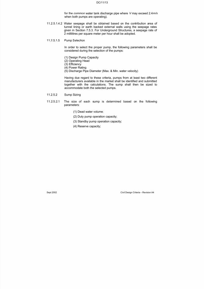
7/18/2019 LTA Civil_standards- Civil Design Criteria
http://slidepdf.com/reader/full/lta-civilstandards-civil-design-criteria 244/345
DC/11/13
Sept 2002 Civil Design Criteria – Revision A4
for the common water tank discharge pipe where V may exceed 2.4m/s
when both pumps are operating).
11.2.5.1.4.2 Water seepage shall be obtained based on the contribution area of tunnel lining or earth backed external walls using the seepage ratesgiven in Section 7.5.3. For Underground Structures, a seepage rate of 2 millilitres per square meter per hour shall be adopted.
11.2.5.1.5 Pump Selection
In order to select the proper pump, the following parameters shall beconsidered during the selection of the pumps:
(1) Design Pump Capacity(2) Operating Head(3) Efficiency(4) Power Rating(5) Discharge Pipe Diameter (Max. & Min. water velocity)
Having due regard to these criteria, pumps from at least two differentmanufacturers available in the market shall be identified and submittedtogether with the calculations. The sump shall then be sized toaccommodate both the selected pumps.
11.2.5.2 Sump Sizing
11.2.5.2.1 The size of each sump is determined based on the followingparameters:
(1) Dead water volume;(2) Duty pump operation capacity;
(3) Standby pump operation capacity;
(4) Reserve capacity;

7/18/2019 LTA Civil_standards- Civil Design Criteria
http://slidepdf.com/reader/full/lta-civilstandards-civil-design-criteria 245/345
DC/11/14
Sept 2002 Civil Design Criteria – Revision A4
11.2.5.2.2 The typical operating water levels of a 2 pump sump shall be as shownin Figure 11.1 below.
11.2.5.2.3 Dead Water Volume
Dead water volume is measured from the Sump Base Level to the AllPump Stop Level and shall be minimised by haunching the base of thesump.
11.2.5.2.4 Duty Pump Operation Storage Capacity
The Duty Pump Operation Storage Capacity is measured from the AllPump Stop Level to the Duty Pump Start Level. The volume shall be
computed from:
4
xT QV select
D =
where Qselect is the higher flow capacity of the selected pumps (seeabove).
T is the time between 2 sequential starts (i.e., one complete start-stopcycle) and is computed from:
T( ) Hour per StopsStart of No −
=
.3600 seconds
Total No. of Starts/Stops per Hour shall not exceed 10 and the levelbetween the All Pump Stop Level to the Duty Pump Start Level shallnot be less than 100mm.
Sump Base Level
All Pump Stop Level
Duty Pump Start Level
All Pump Start Level
Alarm Level
Lowest Inlet Pipe Level
Top of Sump
Reserve Capacity, VR
Dead Water Volume
Duty Pump operation
storage capacity, VD
Standby Pump operation
storage capacity, VS
100mm
DR ≥ 100mm
DD ≥ 100mm
100mm ≤ DS ≤ 200mm
Fig. 11.1: Pump Operating Levels for Sump Sizing
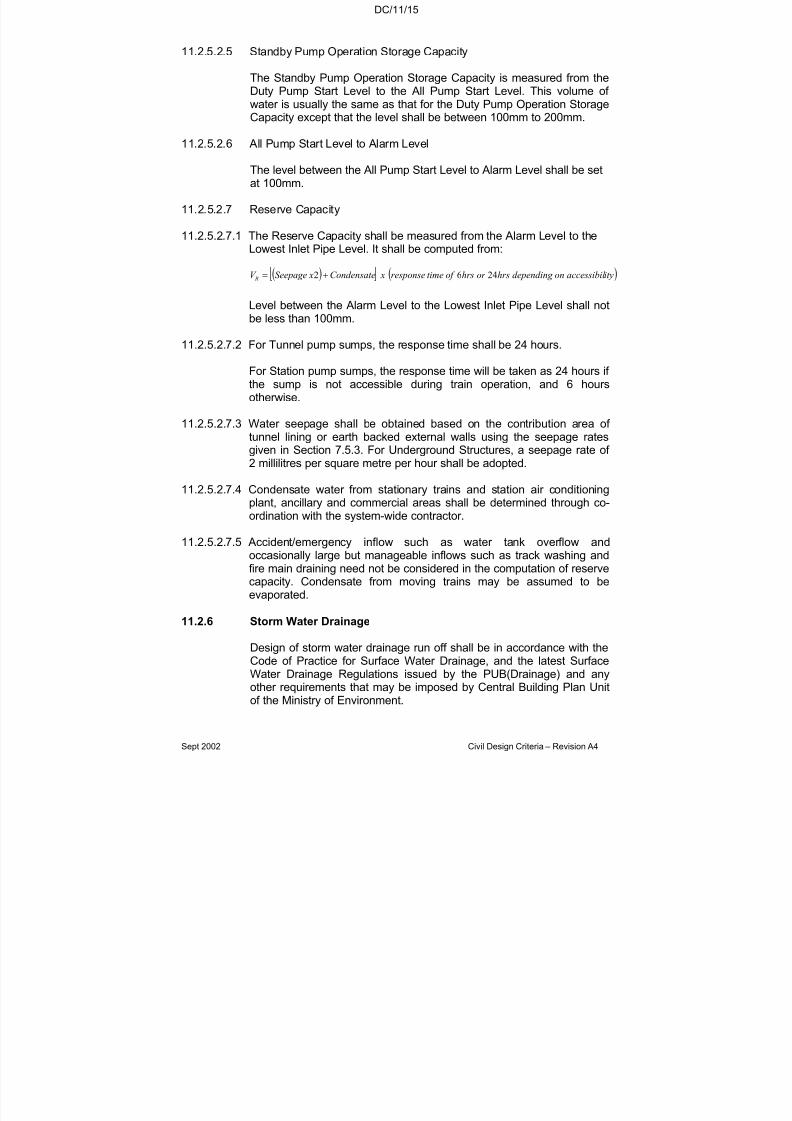
7/18/2019 LTA Civil_standards- Civil Design Criteria
http://slidepdf.com/reader/full/lta-civilstandards-civil-design-criteria 246/345
DC/11/15
Sept 2002 Civil Design Criteria – Revision A4
11.2.5.2.5 Standby Pump Operation Storage Capacity
The Standby Pump Operation Storage Capacity is measured from theDuty Pump Start Level to the All Pump Start Level. This volume of water is usually the same as that for the Duty Pump Operation StorageCapacity except that the level shall be between 100mm to 200mm.
11.2.5.2.6 All Pump Start Level to Alarm Level
The level between the All Pump Start Level to Alarm Level shall be setat 100mm.
11.2.5.2.7 Reserve Capacity
11.2.5.2.7.1 The Reserve Capacity shall be measured from the Alarm Level to theLowest Inlet Pipe Level. It shall be computed from:
( ) ( )ityaccessibil ondepending hrsor hrsof timeresponse xCondensate xSeepageV R 2462 +=
Level between the Alarm Level to the Lowest Inlet Pipe Level shall notbe less than 100mm.
11.2.5.2.7.2 For Tunnel pump sumps, the response time shall be 24 hours.
For Station pump sumps, the response time will be taken as 24 hours if the sump is not accessible during train operation, and 6 hoursotherwise.
11.2.5.2.7.3 Water seepage shall be obtained based on the contribution area of
tunnel lining or earth backed external walls using the seepage ratesgiven in Section 7.5.3. For Underground Structures, a seepage rate of 2 millilitres per square metre per hour shall be adopted.
11.2.5.2.7.4 Condensate water from stationary trains and station air conditioningplant, ancillary and commercial areas shall be determined through co-ordination with the system-wide contractor.
11.2.5.2.7.5 Accident/emergency inflow such as water tank overflow andoccasionally large but manageable inflows such as track washing andfire main draining need not be considered in the computation of reserve
capacity. Condensate from moving trains may be assumed to beevaporated.
11.2.6 Storm Water Drainage
Design of storm water drainage run off shall be in accordance with theCode of Practice for Surface Water Drainage, and the latest SurfaceWater Drainage Regulations issued by the PUB(Drainage) and anyother requirements that may be imposed by Central Building Plan Unitof the Ministry of Environment.
7/18/2019 LTA Civil_standards- Civil Design Criteria
http://slidepdf.com/reader/full/lta-civilstandards-civil-design-criteria 247/345
DC/11/16
Sept 2002 Civil Design Criteria – Revision A4
11.2.6.1 Rainfall and Run Off
The Rational Formula shall be used for determining surface water runoff. The coefficient of run off for cutting slopes and track area shall betaken as 1.0. The design shall be based on a storm of 200 years returnperiod.
Run-off from neighbouring lot or adjacent land if affected shall bediverted by new drains constructed to the approval of PUB(Drainage).
11.2.6.2 Roof Drainage
11.2.6.2.1 Roof drainage shall be designed and constructed to dissipate water from the roof by the most effective and direct route possible to thesurface drains. Design of roof drainage shall be in accordance with allthe latest PUB regulations and with the latest edition of SS CP26 Codeof Practice for Drainage of Roofs. Rainwater outside the station shallnot be drained into the Station/Tunnel pumped drainage system.
11.2.6.2.2 Rainwater pipes and outlets provided to any flat roof shall ensure thatthe build up of water during a flash storm does not exceed 30 mm.
11.2.6.2.3 Rainwater pipes shall be of sufficient bore, and in long lengths witheasy bends to ensure that a back up of water does not occur. Theoutlets to flat roofs shall be filled with dome grating or equivalent (PUBapproved type) to prevent dirt, leaves or any foreign substance fromblocking the down pipe.
11.2.6.2.4 Notwithstanding the above, flat roofs shall be provided with overflow
facilities.
11.2.6.2.5 Wherever pitched roofs form part of the structure, adequate overhangof the roof shall be provided to prevent rainwater water falling ontopeople who are liable to stand or walk beside the building and therainwater must be drained to the surface drainage system. Sufficientsurface water drains shall be provided on the ground level to collect allwater from the roof and prevent ponding of water. Roof gutters shall beavoided as far as possible. Where it cannot be avoided, then gutters of sufficient capacity to collect rainwater from the roof without spillageshall be provided across the edge of the roof. Roof gutters shall be
coated with an approved waterproofing membrane with minimum tenyears warranty and roof outlets shall be properly dressed and sealedwith a suitable membrane at the junction with the roof. Overflow pipesshall be provided at the ends of the gutters.
11.2.6.2.6 Rainwater downpipes shall be positioned at suitable distances to collectand discharge water to the stormwater drainage system. All gutters,outlets and downpipes shall be positioned outside buildings as far aspossible so that if any leak occurs, no damage to sensitive equipment,or other inconvenience, can arise. Rainwater downpipes shall be fittedwith screw-on rodding eyes at the base of the stack.
7/18/2019 LTA Civil_standards- Civil Design Criteria
http://slidepdf.com/reader/full/lta-civilstandards-civil-design-criteria 248/345
DC/11/17
Sept 2002 Civil Design Criteria – Revision A4
11.2.6.3 Paved Areas
All paved areas around the station shall be sloped to provide effectivesurface run-off. The slope shall be directed away from stationentrances. Adequate cut off drains shall be provided and directed intothe existing storm water drainage system.
Where perimeter drains and a surface structure are provided the drainshall be integral with the main structure to avoid differential settlementproblems.
11.3 SEWERAGE & SANITARY PLUMBING
11.3.1 General
General requirements are summarised in Table 11.3. The sewerage
and sanitary system shall incorporate these requirements and shall bedesigned in accordance with Section 11.3.3. Design of sewerage andsanitary system shall also comply with all requirements that may beimposed by the Central Building Plan Unit of the Ministry of Environment.
11.3.2 Design Code
The design of sewerage drainage system shall be in accordance withthe latest PUB Sewerage Department Code of Practice on SanitaryPlumbing and Drainage System, Sanitary Plumbing and Drainage
System Regulations, Sewerage Procedures and RequirementsHandbook by PUB, the Code of Practice on Sanitary Facilities andFittings for Public Toilets and the Code of practice on Pollution Control.
TABLE 11.3
SEWERAGE SYSTEM PROVISION IN STATIONS
Room/Area Requirement Remarks
1 Escalator pit One floor trap per pit. See Section 11.2.3.2.

7/18/2019 LTA Civil_standards- Civil Design Criteria
http://slidepdf.com/reader/full/lta-civilstandards-civil-design-criteria 249/345
DC/11/18
Sept 2002 Civil Design Criteria – Revision A4
TABLE 11.3 (Cont’d)
SEWERAGE SYSTEM PROVISION IN STATIONS
Room/Area Requirement Remarks
2 All ECS associatedPlant Rooms
Minimum of two floor traps per plant room.
Actual number depends onequipment layout androom size.
Floor traps to be locatedadjacent to taps beingprovided for the cleaning of ECS equipment. A 1X1 mkerbed, floor basin to beprovided where necessary.
3 AHU for Generator room
One floor trap For collecting of washingwater during cleaning of cooling coils.
4 Cooling towers /
exhaust plenum
One floor trap plus
service channel if necessary
For bleed off, overflow and
cleaning evaporation water.
5 Sprinkler water tank/pump room
One floor trap withkerb all around.
For washing water duringcleaning of equipment
6 Fuel Tank/Pump room One grease trap For washing water
7 Domestic water tank/pump room
One floor trap withkerb all around.
For washing water duringcleaning of equipment
8 Cooling water tank/pump room
One floor trap withkerb all around.
For washing water duringcleaning of equipment
9 Ancillary rooms,station control roomand commercial areas(shops, kiosks etc.)
Floor traps wherenecessary
Preferred location for floor traps would be the corridor areas.
10 Cleaner room One floor trap For washing water.
11 Refuse store One floor trap For washing water.
12 Bin point / Bin centre(outdoor)
Gully trap For washing water.
7/18/2019 LTA Civil_standards- Civil Design Criteria
http://slidepdf.com/reader/full/lta-civilstandards-civil-design-criteria 250/345
DC/11/19
Sept 2002 Civil Design Criteria – Revision A4
TABLE 11.3 (Cont’d)
SEWERAGE SYSTEM PROVISION IN STATIONS
Room/Area Requirement Remarks
13 Staff room Floor trap For wash basin.
14 Staff and public toilet Floor trap For washing water.
15 Within WC cubical Floor drain/trap Follow PUB guideline.
16 *Kitchen in CD station 3 floor traps One floor trap adjacent toeach sink unit and RC washbasin. Additional floor trapadjacent to pressure cookers.
17 *Sanitary room Floor trap Waste water.
18 *Dry toilet areas Sealed floor traps. For waste from wash basin.The floor traps shall becovered with floor accessplates during peace time.Location and spacing shall beas per BCA guidelines.
* These are civil defence facilities in CD stations. These facilities will only be usedduring CD operations.
11.3.3 Design Directives
11.3.3.1 Sewerage and Sanitary Plumbing System shall be constructed usingapproved materials, laid to fall in accordance with PUB’s requirements.Waste traps shall be of a deep seal anti-syphonic type. Waste pipesshall discharge into open trapped gullies with back inlets, connected tomanholes constructed of high quality impervious materials properlyformed to withstand contamination from mild acid. Allowance shall bemade for the proper venting and rodding of the sewerage system.
11.3.3.2 The manhole covers within the station shall be medium duty doubleseal, double cover, screw down recessed type to accommodate a
finished floor. Where there is vehicular traffic, manhole covers shall beheavy duty and made of cast iron.
11.3.3.3 Wherever possible sewage shall be gravity fed into the main seweragenetwork.
11.3.3.4 The pipe work where fixed to walls or under slabs shall be secured withbrackets and hangers capable of supporting the fully loaded pipes.

7/18/2019 LTA Civil_standards- Civil Design Criteria
http://slidepdf.com/reader/full/lta-civilstandards-civil-design-criteria 251/345
DC/11/20
Sept 2002 Civil Design Criteria – Revision A4
11.3.3.5 On vertical stacks and on all branch connections rodding eyes shall befitted to bends not exceeding 135
oor at connections between pipes of
different material.
11.3.3.6 All pipes shall be properly caulked and sealed at the joints and shall beto the PUB’s approval.
11.3.3.7 The PUB approved type of autosensing/electronic sensor flush valvesshall be provided for water closets and urinals at public toilets and staff toilets. Where water pressure is inadequate for the operation of theseflush valves, water tanks with booster pumps shall be provided.Sufficient and adequate power supply shall be available to operatethese flush valves.
11.3.3.8 Penetrations through beams, slabs or any structural members for wastepipes shall be avoided as far as possible.
11.3.3.9 Floor traps/wastes shall be placed with consideration to water
areas/points for which the provision is made. Floor traps shall not beobstructed or covered in any manner to hinder access to maintenancepersonnel.
11.3.3.10 The floor of all ECS associated plant rooms (e.g., ECS Plant Room, AHU Plant Room etc.) shall be waterproofed using an accepted liquidapplied membrane.
11.3.4 Sewage Pump Sumps
The design of sewage pump sumps shall be similar to that of the
drainage pump sumps except that they collect and dispose wastewater.
11.3.5 Sewage Ejector
11.3.5.1 Sewage ejectors shall be provided at the base level of undergroundstations for the collection and disposal of sewage from staff toilets,crew toilets, public toilets and waste water from plant rooms/areas. Allsewage and wastewater from ground level or above shall be directlydisposed into the main sewerage network by gravity as far as possible.
11.3.5.2 At least two sewage ejector/sewage pumping systems, preferably ateach end of the station shall be provided for all underground stations.Each station shall not have more than three sewage ejector/sewagepumping systems.
11.3.5.3 For CD Stations, no ejector/sewage pumping system shall be designedto serve only CD facilities. Facilities that operate only during CD Mode(e.g., dry toilet) will result in low usage of the ejector/sewage pumpsand increase maintenance burden in the future. Hence, anyejector/sewage pumping system shall be designed for either peacetime facilities or for both CD and peacetime facilities.
7/18/2019 LTA Civil_standards- Civil Design Criteria
http://slidepdf.com/reader/full/lta-civilstandards-civil-design-criteria 252/345
DC/11/21
Sept 2002 Civil Design Criteria – Revision A4
11.3.5.4 Ejectors shall be positioned in rooms specifically designated for thispurpose and with direct access facilities for maintenance. A minimum of two pumps shall be provided for each ejector system. Ejector roomsshall be a minimum size of 3mx3m to comply with PUB’s requirement.
11.3.5.5 Access opening shall be provided directly above the ejector tanks andpumps for easy removal/replacement. Access openings shall be fitted
with aluminium chequered covers and provided with aluminium alloyaccess ladders with extensible handhold up to 1150mm above accesscover level. Ladder requirements are described in Section 11.5.
11.3.5.6 Lifting facilities (e.g., overhead runway beam, eye bolt etc.) andequipment shall be provided to enable easy lifting of the ejector tanks/pumps. Adequate removable chain blocks shall be provided.Sufficient clearance all around the sewage ejector shall be provided for ease of maintenance.
11.3.5.7 Containment of over spillage of sewage from ejector tank shall be
considered. A sewage sump pump shall be provided in every ejector room and connected to the ejector pumping main.
11.3.5.8 For both ejector and sewage pumps, the minimum and maximum flowvelocities allowed in the discharge pipe shall be 1.0m/s and 2.4m/srespectively. This is to ensure self cleansing velocity and to preventscouring of pipes. For each ejector/sewage pumping system, thepumps shall be designed for 3 times the peak sewage/wastewater inflow generated.
11.3.5.9 Discharge pipework of minimum 100mm diameter shall consist of
check valve of single flap type and a gate valve. They shall be locatedabove the ejector tanks such that they are accessible without the needto enter the ejector sump and after removal of the access cover.
11.4 WATER SERVICES
11.4.1 General
11.4.1.1 The design of water supply to stations shall comply with the latestSingapore Standard CP 48 for Water Services and Public Utilities
(water supply) Regulations. The Contractor shall be responsible for thesubmission of water reticulation system for PUB approval. TheContractor shall incorporate appropriate water conservation measuresgiven in SS CP 48 in the design.
11.4.1.2 Underground piping shall be laid at such a depth that it is unlikely to bedamaged by traffic loads and vibration. Where piping has to be laid inany ground liable to subsidence then special consideration shall begiven to the type of piping to be used and the type of joint to beadopted in order to minimise risk of damage due to settlement. Where
7/18/2019 LTA Civil_standards- Civil Design Criteria
http://slidepdf.com/reader/full/lta-civilstandards-civil-design-criteria 253/345
DC/11/22
Sept 2002 Civil Design Criteria – Revision A4
piping has to be laid across recently disturbed ground, continuouslongitudinal support shall be provided.
11.4.1.3 Choice of materials for water reticulation system within the station shallconform to the latest list of approved water pipe fittings, water storagetanks and other water service appurtenances issued by the Water Department (PUB) and where specified in the M&W Specification.
11.4.1.4 Provision shall be made at every bend, branch and dead end in a mainto resist the hydraulic thrust.
11.4.1.5 Chambers to house PUB’s water meters shall be provided inaccordance with CP 48 standard detail. The chamber shall be providedabove ground level. Wherever possible, a separate chamber to housethe double check valve assembly for the fire fighting line shall beprovided and located below ground level if it is technically feasible witha drainage facility to prevent flooding of the underground chamber.Location of the water meter chamber shall be easily accessible and
unobstructed, and shall be approximately 1m from the site boundary.
11.4.1.6 Common water distribution pipes shall not be routed in tenantable area.
11.4.1.7 All valves and taps must be accessible for service and maintenance.Where valves or taps are installed above the ceiling or behind walls(seepage walls etc.) appropriate access panels must be provided in theceilings or walls for maintenance and repair of the valves and taps.Control valves shall be provided at strategic and easy access location.
Adequate brackets supports must be provided to the supply pipe in thevicinity of the bends.
11.4.1.8 Water supply to the stations falls into the following categories:
(a) a potable water system
(b) a water system for fire fighting
(c) a Civil Defence (CD) water supply where applicable
(d) a cooling water make-up system for ECS
(e) a water supply system for plant and equipment operation
(f) a water supply system for trains/plant/machinery/
equipment washing(g) a water system for irrigation
11.4.2 Water Supply System
11.4.2.1 Drinking water tank/pump room shall not be located next to an ejector room or toilet or any potentially polluted area.
The areas/rooms in stations that require water supply provisions aregiven in Table 11.4.

7/18/2019 LTA Civil_standards- Civil Design Criteria
http://slidepdf.com/reader/full/lta-civilstandards-civil-design-criteria 254/345
DC/11/23
Sept 2002 Civil Design Criteria – Revision A4
TABLE 11.4
WATER SUPPLY PROVISION IN STATION
Room/Area Requirements Remarks
1. Sprinkler Water tank/Pump room
One tap For washing purpose.
2. Cleaner Room One tap with sink
3. Refuse Store One tap
4. Bin Point/Bin Centre One tap
5. Staff Room One tap with sink
6. Toilets Taps as necessary Taps in WC cubicles withsquatting pans to meet PUBrequirements.
7. Planter in Stations Taps as necessary Liase with PUB/Nparks/ENV tomeet their specificrequirements, if any.
8. Kitchen in CDStation
As per CDrequirements
9. Sanitary Control
Room
As per CD
requirements
10. All ECS associatedPlant Rooms
Three taps - Near condensing unit.- Near AHU.- Near filter.
11. Fuel Tank/PumpRoom
One tap with sink
12. Ejector Room One tap
13. Drainage PumpRoom
One tap
14. Domestic Water Tank/Pump Room
One tap For washing purpose.
15. Cooling Tower Room/Area
One tap For washing purpose.
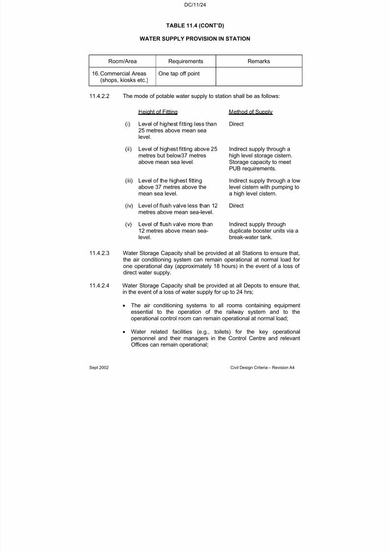
7/18/2019 LTA Civil_standards- Civil Design Criteria
http://slidepdf.com/reader/full/lta-civilstandards-civil-design-criteria 255/345
DC/11/24
Sept 2002 Civil Design Criteria – Revision A4
TABLE 11.4 (CONT’D)
WATER SUPPLY PROVISION IN STATION
Room/Area Requirements Remarks
16. Commercial Areas(shops, kiosks etc.)
One tap off point
11.4.2.2 The mode of potable water supply to station shall be as follows:
Height of Fitting Method of Supply
(i) Level of highest fitting less than25 metres above mean sealevel.
Direct
(ii) Level of highest fitting above 25metres but below37 metresabove mean sea level.
Indirect supply through ahigh level storage cistern.Storage capacity to meetPUB requirements.
(iii) Level of the highest fittingabove 37 metres above themean sea level.
Indirect supply through a lowlevel cistern with pumping toa high level cistern.
(iv) Level of flush valve less than 12
metres above mean sea-level.
Direct
(v) Level of flush valve more than12 metres above mean sea-level.
Indirect supply throughduplicate booster units via abreak-water tank.
11.4.2.3 Water Storage Capacity shall be provided at all Stations to ensure that,the air conditioning system can remain operational at normal load for one operational day (approximately 18 hours) in the event of a loss of direct water supply.
11.4.2.4 Water Storage Capacity shall be provided at all Depots to ensure that,in the event of a loss of water supply for up to 24 hrs;
• The air conditioning systems to all rooms containing equipmentessential to the operation of the railway system and to theoperational control room can remain operational at normal load;
• Water related facilities (e.g., toilets) for the key operationalpersonnel and their managers in the Control Centre and relevantOffices can remain operational;
7/18/2019 LTA Civil_standards- Civil Design Criteria
http://slidepdf.com/reader/full/lta-civilstandards-civil-design-criteria 256/345
DC/11/25
Sept 2002 Civil Design Criteria – Revision A4
• Any other facilities essential to the operation of the depot canremain operational.
The water supply to these facilities shall be a separate supply through adedicated storage tank, so that “ramping down” of other non essentialfacilities will not be taken from this supply.
11.4.2.5 Water booster system shall be provided with back-up power supply or be connected to the Uninterrupted Power Supply system of thestation/depot such that in event of power failure, should the stations,depot and trains remain operational, the water booster system shallalso remain operational.
11.4.3 Water System for Fire Fighting
If a fire engine access road is provided, every part of the fire engineaccess road shall be within an unobstructed distance of 50m from ahydrant. Where a public hydrant is not available, private hydrant(s) fed
after the water meter shall be provided in accordance with SS CP29and PUB Regulations.
In all cases, a 100 mm X 150 mm branch line tee-off after the water meter shall be laid to supply water directly to the sprinkler water tank.
Fire hydrants shall be supplied and installed by the Contractor.
11.4.4 Civil Defence (CD) Water System
Where such a system is required, it shall be designed in accordance
with CD requirements.
11.5 ACCESS LADDERS
11.5.1 General
Access ladders shall be provided n the following instances.
(a) Access to equipment where regular maintenance works isrequired.
(b) Escape or emergency exit purposes.
(c) Any other situations where it is essential to provide one.(e.g., underplatform voids in stations, air shafts etc.)
7/18/2019 LTA Civil_standards- Civil Design Criteria
http://slidepdf.com/reader/full/lta-civilstandards-civil-design-criteria 257/345
DC/11/26
Sept 2002 Civil Design Criteria – Revision A4
11.5.2 Design
The design shall conform to BS 5395: Part 3. All fixings to the structureshall be designed in accordance with Chapter 8. The minimum boltdiameter shall be M12.
Extendable type handrails shall be provided where it is not practical to
extend side strings above the landing level to form handrails (for example sump pits in cross passages where pedestrian access isrequired over the sump pit). They shall be provided at each string andshall be capable of being temporarily extended to provide temporaryhandrails.
11.5.3 Material
The material shall be stainless steel or aluminium. Where steel tubingis used, the thickness shall not be less than 4.0 mm.
7/18/2019 LTA Civil_standards- Civil Design Criteria
http://slidepdf.com/reader/full/lta-civilstandards-civil-design-criteria 258/345
DC/12/1
Sept 2002 Civil Design Criteria – Revision A4
CHAPTER 12
EXTERNAL WORKS
12.1 LAND BOUNDARIES
12.1.1 In determining the design of the Works, the designer shall take intoaccount the land available to the Authority and the need to optimiseland use. Existing land boundaries shall be observed to avoid adverseencroachment to adjacent properties.
12.1.2 Where land will be sterilised for the exclusive use of a railway system,such land shall be alienated to the Authority under lease. This land willbe used for such facilities as :
a. Elevated Stationsb. Depots
c. Substation and Relay Stationsd. At-Grade Sections of Railwaye. Railway Approach Structures
Elsewhere, the Authority holds easements for tunnels, viaducts, andcommuter subways. Underground Railway stations are held under “subterranean title”, with the station’s related structures protrudingabove ground, such as escape shafts, ventilation shafts, and entrancesare held under easement.
12.1.3 For road design, the designer shall take into account that the roads are
only built on State Land. Such State Land shall include those parcelsof private land which have been identified to be acquired for the roadproject as well as those which had been set aside for road purposes asstipulated under a related planning condition.
12.1.4 In addition to the use of State Land, the Streets Work Act allows for thepermanent placement of road tunnels and viaduct columns supportingelevated roads on private land.
12.1.5 The layout of the Works shall take into account proposed and existingland boundaries to make full utilisation of available land. Excision of
land parcels leading to creation of remnant unusable plots shall beavoided.
12.1.6 All facilities (for example lighting posts, handrails, ICs, utility servicemeters, etc.) that serve the Works shall be sited within the alienatedland boundary. No such facilities or the building structures shallencroach into adjacent plots. For railway works, commuter facilitiessuch as footpaths and other road-related structures are excluded fromthis requirement.

7/18/2019 LTA Civil_standards- Civil Design Criteria
http://slidepdf.com/reader/full/lta-civilstandards-civil-design-criteria 259/345
DC/12/2
Sept 2002 Civil Design Criteria – Revision A4
12.1.7 All site layout plans, including those of working sites and casting yardsshall show existing cadastral information, Road Reserves Lines,Railway Protection Zones and Drainage Reserves. The designer isadvised that this information available from government agencies is of lower accuracy and only locally consistent when compared to theprecise survey controls established for the construction of a railwayproject. Due allowance in the form of specific field surveys to resolve
critical differences shall be made in site layout design.
12.2 FLOOD PROTECTION
12.2.1 The Design Flood Level (or minimum platform level) shall be derivedfrom the highest flood levels as recorded by the PUB (Drainage).Design Flood level shall be taken as 1m above the highest recordedflood level at each location unless advised otherwise by PUB(Drainage).
12.2.2 For areas with no flood record, Design Flood Level shall generally be1m above the existing ground or road level. However PUB (Drainage)may accept a lower level based on topographic considerations.
12.2.3 All entrances, vent shafts openings, tunnel portals and other openingsinto underground railway structures and all road thresholds andperimeters to depressed carriageways, underpasses and road tunnelsshall be built above the Design Flood Level. Where drainage or sewerage pipes discharge from the underground structure into thesurface system, swan necks shall be provided at a level above theDesign Flood Level. If gravity drainage provisions are made, the
drainage exit points shall be above the Design Flood Level to preventany back flow of water into the sub-surface structures during floods.
12.2.4 Where entrances, vent shafts, tunnel portals or other openings intounderground railway structures are located on a raised platform, thethreshold level of the opening shall be at least 150mm higher (crestprotection) than the platform level to prevent local flash floodingentering the underground structures. At entrances, this requirementshall be met by sloping the surface away from the threshold and not bya step.
12.2.5 Any development with underground links to the underground facilitiesshall also comply with the above requirements.
12.2.6 All arrangements for flood protection shall meet the requirements of PUB Drainage Department.
12.3 PAVED AREAS
12.3.1 Paved areas around structures shall be designed to withstand theloads likely to be experienced during delivery and removal of
7/18/2019 LTA Civil_standards- Civil Design Criteria
http://slidepdf.com/reader/full/lta-civilstandards-civil-design-criteria 260/345
DC/12/3
Sept 2002 Civil Design Criteria – Revision A4
equipment. Where fire engine access is required, it shall be metalledor paved to withstand the weight of a 20 tonne fire engine or asspecified by Fire Service Bureau. Besides, such access roads must beable to accommodate the entry and manoeuvring of fire engines andfire service appliances.
12.3.2 Movement joints shall be provided at not more than 8.5m spacing and
designed to prevent cracking of finishes.
Movement joints shall be provided at the interface of non-suspendedand suspended areas. Differential settlements at these joints shall besuch that the difference in level between the areas will not be a hazardto persons using the areas and in no case shall the differentialsettlements exceed 6 mm.
12.3.3 Maximum allowable settlement in the pavement structure around thestation shall not exceed 20 mm. The differential settlement betweenany two adjacent points within a panel shall not exceed 1 : 1000
subject to a maximum of 15 mm. The differential settlement betweenany two adjacent panels shall not exceed 6 mm. All external pavingshall be designed to drain off surface water efficiently to preventponding of water.
12.4 IRRIGATION SYSTEMS AND LANDSCAPING
Irrigation systems, landscaping and irrigation of land through viaductdischarge shall comply with the requirements of the National ParksBoard, and all other relevant government bodies. Each irrigation
system shall be proven to be workable by means of a trial of adequatetime period.
12.5 HANDRAILS AND RAILINGS
12.5.1 Handrails shall be designed for loadings in accordance to therequirements of Chapter 3 of this Specification.
12.5.2 Handrails are required where there is a sudden drop inground/pavement levels.
12,5,3 Standard safety railing shall be provided for all open drains more than1m deep. The railings shall be erected, galvanised and painted inaccordance with the latest standard galvanised safety railings specifiedin the Code of Practice on Surface Water Drainage.
12.5.4 Where railings are required in areas outside the station premises for public safety, they shall be provided in accordance with the latest LTAStandard Railings Details.
7/18/2019 LTA Civil_standards- Civil Design Criteria
http://slidepdf.com/reader/full/lta-civilstandards-civil-design-criteria 261/345
DC/12/4
Sept 2002 Civil Design Criteria – Revision A4
12.6 FENCING AND PROTECTION AGAINST UNAUTHORISED ACCESS
12.6.1 The sites listed under (b), (c), and (d) in Clause 12.1.2 shall be fencedin accordance with existing Building Regulations.
12.6.2 For railway approach structures, appropriate measures shall beincorporated in the design to make it impossible for the public to access
the railway tracks.
7/18/2019 LTA Civil_standards- Civil Design Criteria
http://slidepdf.com/reader/full/lta-civilstandards-civil-design-criteria 262/345
DC/13/1
Sept 2002 Civil Design Criteria – Revision A4
CHAPTER 13
E&M INTERFACE
13.1 GENERAL
This chapter covers particular E&M requirements that are to beincorporated into the C&S design.
13.2 ELECTRICAL SUBSTATION
Electrical substations are required within the stations and as independentstructures within the depot.
13.2.1 Cable Chamber
13.2.1.1 A cable chamber shall be provided beneath the full area of the electrical
equipment rooms. The chamber shall be a through void as far aspracticable and treated as one fire compartment. The cable chamber shall have a height of at least 1700 mm.
13.2.1.2 The cable chamber should be dry and free of water. Cable entry into thecable chamber through external ducts shall be sealed by means of amultiple cable transit (MCT). The cable chamber shall be waterproofed.
13.2.1.3 The cable chamber floor shall slope towards one end and floor wastesshall be provided for draining of any water present in the cable chamber and connected to the surface water drainage system.
13.2.1.4 Where it is not possible to construct main access door(s) to the cablechamber at least two manholes of 750 mm x 750 mm size shall beprovided. These manholes shall be complete with a galvanised steelladder complete with hand-rungs. The manhole cover shall be lightenough for one man to handle and designed to withstand 5 kN/m2 liveload. These manholes shall be located at the two ends of the equipmentroom, flush to the floor, free from any obstruction and away from theescape route.
13.2.2 Others
13.2.2.1 Fixed pulling points (eyebolts) of appropriate tonnage shall be providedin the transformer rooms for installation and withdrawal of thetransformers. The eyebolts must be recessed to the wall or floor. Thosein the floor shall be provided with a cover and fitted flush to the floor
7/18/2019 LTA Civil_standards- Civil Design Criteria
http://slidepdf.com/reader/full/lta-civilstandards-civil-design-criteria 263/345
DC/13/2
Sept 2002 Civil Design Criteria – Revision A4
surface. Each eyebolt shall be tested to 1.5 times safe working loadand certified by a Mechanical Professional Engineer.
13.3 PLATFORM TOUCH VOLTAGE PROTECTION
13.3.1 General
13.3.1.1 The Contractor shall design and detail an effective platform insulationsystem to prevent passengers on the platform from possible electricshocks caused by touch voltage when boarding/alighting or touching thetrain or when touching the Platform Screen Doors (PSDs).
13.3.1.2 A “protection zone” (as defined below) by the platform edge areasadjacent to the tracks shall be electrically isolated (for example, from thestation structure/electrical earth, or from traction earth, etc.) Allappurtenances and the finishes to all structures (including floors, wallsand columns) that fall within the protection zone shall be electricallyisolated from earth, or provided with a suitable insulated coating, to avoid
harmful touch potentials..
13.3.1.3 The extent of the protection zone shall be :
• vertically, between the top of platform structural slab level and aminimum 2.5 metres above platform finished floor level.
• transversely, from the platform edge to to a minimum distance of 1.8metres into the platform from any part of the inner face of the platformscreen doors (PSDs) assembly, and from any metallic clad platformedge column,
• longitudinally, for the full length of the platform, and into the “buffet”
areas beyond to encompass anywhere that is within 1.8 metres of thePSD assembly end returns or within 1.8 metres of a train whenstopped at the station at its most adverse allowable stoppingtolerance (refer to signalling designer).
13.1.4 The finishes to the platform between the platform edge and the remoteside of the protection zone shall be fully electrically insulated from thestructural slab below, and from all adjacent finishes and/or structures atthe boundaries of the protection zone.
13.1.5 All cladding, including vitreous enamel, on walls or columns shall use
electrically insulated fixings. Skirtings around walls or columns that fallwithin the protection zone shall also be isolated.
7/18/2019 LTA Civil_standards- Civil Design Criteria
http://slidepdf.com/reader/full/lta-civilstandards-civil-design-criteria 264/345
DC/13/3
Sept 2002 Civil Design Criteria – Revision A4
13.1.6 Insulated breaks in the finishes shall be provided at the boundaries of theprotection zone to ensure that the isolated areas are not earthed to thenon-isolated areas.
13.1.7 Metallic handrails that run along the platform edge in the buffet areasand which fall within the protection zone shall have an insulated finish.
13.3.2 Minimum Insulation Level
13.3.2.1 Notwithstanding 13.3.1 above, the minimum insulation levels shall be:-
a) A minimum platform floor to earth resistance of 10,000 and 35,000ohm over a 300 x 300 mm area at 250V DC under damp and dryconditions respectively.
b) A metallic finishes (e.g. handrails, metallic cladding, etc.) to earthresistance of 50,000 ohm at 500V DC under damp condition.
13.3.3 Insulation Details
No embedded conduit, trunking or service pipe shall be allowed to run inor through the insulated areas.
No metal dividing strip shall be allowed on the platform finishes withininsulated areas.
Expansion joints on platform shall be kept to a minimum. Expansion joints shall not allow passage of water or moisture.
13.4 WATER AND ELECTRICAL EQUIPMENT
13.4.1 General Protection
13.4.1.1 No water pipe whether gravity fed or under mains pressure shall belocated within electrical rooms (substations, switch rooms, signal rooms,battery rooms, CER, etc) or associated cable chambers. Suchprohibited pipes include but are not limited to : -
i) Rain water down pipes;
ii) Sewerage & sanitary plumbing pipes including local penetrationsthrough ceiling slab;
iii) PUB water mains supply;iv) Internal water services plumbing reticulation;v) Sprinkler and dry riser mains;vi) Drainage pipework.

7/18/2019 LTA Civil_standards- Civil Design Criteria
http://slidepdf.com/reader/full/lta-civilstandards-civil-design-criteria 265/345

7/18/2019 LTA Civil_standards- Civil Design Criteria
http://slidepdf.com/reader/full/lta-civilstandards-civil-design-criteria 266/345
DC/13/5
Sept 2002 Civil Design Criteria – Revision A4
provision of demountable louvres, panels, etc. For Civil Defencestations, staging may be necessary in the bomb pits to facilitate themovement of equipment. Such staging should be designed to support astatic load of 20 tonnes, or such higher load as may be required by theSystemwide Contractors. For delivery from tunnels, floor accesshatches above the trainway with lifting beams shall be provided. Thelifting beam capacity shall be the subject of co-ordination between Civil
Contractor and Systemwide Contractor.
13.5.4 Fixed lifting points (eyebolts) shall be provided for installation andreplacement of major pieces of equipment. The minimum requirementsare :-
• For traction substation transformers
of the structure(s) above the transformer, located in front of theintended location of the transformer;- 3 nos. 5 tonne safe working load capacity lifting points
recessed in floor for pulling
• For service substation transformers
- 1 no. 5 tonne safe working load capacity lifting point in soffit of the structure(s) above the transformer, located in front of theintended location of the transformer;
• For escalators
- 8 nos. 5 tonne safe working load capacity lifting points for each
escalator in the soffit of the structure(s) above the escalator
• For lifts
-1 no. 2 tonne safe working load capacity lifting points for eachlift at each lift shaft and each lift motor room
In all cases, location and safe working load shall be co-ordinated with theSystemwide Contractor.
13.6 ELECTRICITY SUPPLY TO CIVIL EQUIPMENT
13.6.1 Various pieces of equipment supplied by the Civil Contractor will requirean electrical supply to operate. The design shall be co-ordinated with theE&M Contractor regarding the location, power requirements, cable

7/18/2019 LTA Civil_standards- Civil Design Criteria
http://slidepdf.com/reader/full/lta-civilstandards-civil-design-criteria 267/345
DC/13/6
Sept 2002 Civil Design Criteria – Revision A4
routing, termination and connection for power supply to all suchequipment.
13.6.2 The equipment supplied by the Civil Contractor requiring power supplyincludes (but may not be limited to) :-
Drainage Pumps
Sewerage EjectorsMotors for Sliding DoorsU.V FiltersHand DryersToilet SensorsMotorised Roller Shutters
Automatic Station Entrance Doors
13.6.3 The design shall allow for a 400/230V supply with a ±10% voltage and
±2% frequency variance at the normal and emergency main low voltagedistribution boards. The design shall be co-ordinated with the Electrical
Services (including UPS) Contractor(s) with respect to the voltage dropbetween the main LV boards and the input terminals of their equipment,to ensure that the equipment will operate over the full range of supplyconditions identified above. The design shall incorporate starting in- rushcurrent reduction equipment where necessary to ensure the tolerancesas “seen” by the equipment are not exceeded.
13.7 EARTHING SYSTEM
13.7.1 General
a) The basic design for the earthing system is indicated on the Authority’s Earthing System Interface Drawing.
b) The Civil Contractor shall carry out individual soil resistivity testat each end of the station prior to construction of the stationbase slab.
The soil resistivity test shall use the Wenner 4-pin method andthe results submitted by the Civil Contractor shall be endorsedby a Registered Electrical Professional Engineer (PE). The CivilContractor shall select a minimum of 2 test locations for eachstation subject to the approval of the Engineer. Five sets of
tests shall be conducted at each location; each set at pinspacing of 2m, 4m, 6m, 8m and 10m respectively.
c) The design, installation and testing of the earthing system shallbe in accordance with SS CP16. As per SS CP16, Section 8,
7/18/2019 LTA Civil_standards- Civil Design Criteria
http://slidepdf.com/reader/full/lta-civilstandards-civil-design-criteria 268/345
DC/13/7
Sept 2002 Civil Design Criteria – Revision A4
the passing criteria for earthing resistance shall be not more
than 1Ω.
d) The Civil Contractor shall prepare the necessary detailed designcalculations, working drawings and test procedures and submitto the Engineer for approval.
13.7.2 Earthing Mat Design Requirements
a) The earthing mat shall be designed to limit the couplingbetween the lightning and the power system earth mat to 110Vwhen a discharge of 100KA from a lightning strike occurs. Thecoupling device connecting the lightning and power systemearthing mats shall be under the scope of the Civil Contractor.The Civil Contractor shall co-ordinate with the Electrical ServicesContractor to ensure that the design meets the specificationrequirements.
13.7.3 Installation and Execution
a) The ringed earthing mat shall comprise earth rods inclusive of 95mm2 bare stranded copper wire laid 300mm below basementslab/ground level. The earth rod shall be made up of twolengths of 1.8m, 16mm diameter copper clad steel rods coupledtogether with silicon aluminium bronze coupling and copper wire
joints are by exothermic weld and must be inspected by theEngineer before backfilling.
b) Earth riser cables 185mm2 cross linked polyethylene (XLPE)
shall be brought from the earth mat up through the basementfloor or wall to each of the equipment rooms and two nos 95mminsulated earth cables from the earthing mat to the two testlocations located aboveground at station air shafts, as shown onAuthority’s Drawing.
c) At each riser cable entry through the basement floor or wall, atinned copper water-stop sleeve shall be provided to prevent theingress of water. The sleeve shall be coated with epoxy resin.
d) The Civil Contractor shall co-ordinate with the Power Supply
Equipment and Cabling Contractor for termination of the earthriser cables onto the main earth bars in accordance with the
Authority’s Earth System Interface Drawing.
7/18/2019 LTA Civil_standards- Civil Design Criteria
http://slidepdf.com/reader/full/lta-civilstandards-civil-design-criteria 269/345
DC/13/8
Sept 2002 Civil Design Criteria – Revision A4
e) The copper electrodes at the earth inspection chamber atground level shall have a label “Electrical Earth - Do NotRemove”.
13.7.4 Testing
a) Upon completion of the earthing mat, a preliminary test shall be
carried out by Contractor’s Electrical PE using earth meggerstested by the Singapore Productivity and Standards Board(PSB).
b) The Civil Contractor shall ensure that the soil resistivity testequipment is calibrated by the Singapore Productivity andStandards Board (PSB) or an accredited laboratory beforecarrying out soil resistivity measurements.
c) Interface co-ordination with Power Supply Equipment & CablingContractor and Electrical Services Contractor’s PE is required
for joint witnessing of all earthing tests.
d) The Civil Contractor shall carry out the following earthing mattests:
i) Individual earthing mat test at each end of stationii) Combined earthing mat testiii) Continuity test after earth risers are terminated on earth
bars, andiv) Final earthing mat test as below
e) The Contractors shall submit plots of each resistance curvetogether with all test results to the Engineer for approval.
f) Four weeks prior to 22 kV power-on of MRT station power supplies, the Contractor’s Electrical PE shall carry out a finalearth test. It is essential that all inspection chambers beproperly completed before the final earth test.
g) The Civil Contractor’s Electrical PE must submit 6 originalcopies of endorsed earthing certificate (Declaration of theEarthing System), test report/results, earthing mat design
calculations and as-built drawings to the Engineer prior to thecommissioning of station power supplies.
7/18/2019 LTA Civil_standards- Civil Design Criteria
http://slidepdf.com/reader/full/lta-civilstandards-civil-design-criteria 270/345
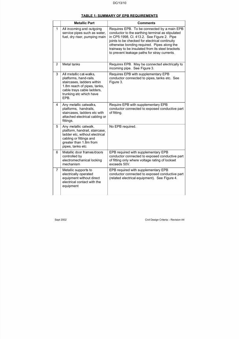
7/18/2019 LTA Civil_standards- Civil Design Criteria
http://slidepdf.com/reader/full/lta-civilstandards-civil-design-criteria 271/345
DC/13/10
Sept 2002 Civil Design Criteria – Revision A4
TABLE 1: SUMMARY OF EPB REQUIREMENTS
Metallic Part Comments
1 All incoming and outgoingservice pipes such as water,fuel, dry riser, pumping main
Requires EPB. To be connected by a main EPBconductor to the earthing terminal as stipulatedin CP5:1998, Cl. 413.2. See Figure 2. Pipe
joints to be checked for electrical continuity
otherwise bonding required. Pipes along thetrainway to be insulated from its steel bracketsto prevent leakage paths for stray currents.
2 Metal tanks Requires EPB. May be connected electrically toincoming pipe. See Figure 3.
3 All metallic cat-walks,platforms, hand-rails,staircases, ladders within1.8m reach of pipes, tanks,cable trays cable ladders,trunking etc which haveEPB.
Requires EPB with supplementary EPBconductor connected to pipes, tanks etc. SeeFigure 3.
4 Any metallic catwalks,platforms, handrails,staircases, ladders etc withattached electrical cabling or fittings.
Require EPB with supplementary EPBconductor connected to exposed conductive partof fitting.
5 Any metallic catwalk,
platform, handrail, staircase,ladder etc, without electricalcabling or fittings andgreater than 1.8m frompipes, tanks etc.
No EPB required.
6 Metallic door frames/doorscontrolled byelectromechanical lockingmechanism
EPB required with supplementary EPBconductor connected to exposed conductive partof fitting only where voltage rating of locksetexceeds 50V.
7 Metallic supports toelectrically operatedequipment without directelectrical contact with theequipment
EPB required with supplementary EPBconductor connected to exposed conductive part(related electrical equipment). See Figure 4.

7/18/2019 LTA Civil_standards- Civil Design Criteria
http://slidepdf.com/reader/full/lta-civilstandards-civil-design-criteria 272/345
DC/13/11
Sept 2002 Civil Design Criteria – Revision A4
TABLE 1: SUMMARY OF EPB REQUIREMENTS (CONT’D)
Metallic Part Comments
8 Electrically operated roller shutters
EPB required with supplementary EPBconductor connected to exposed conductive part(casing of roller shutter motor).
9 Metallic wall cladding(excluding VE)
EPB limited to panels and frameworkcomponents containing, or immediately adjacentto, electrical socket outlet or other sources of electricity. Supplementary EPB conductor connected to exposed conductive part of fitting.See Figure 5. No EPB required for VEpanelling. Details of wall cladding to beexamined to ensure electrical continuitythroughout.
10 Common trunking providedby Civil Contractor
EPB required with supplementary EPBconductor connected to nearest main EPBconductor.
11 Raised floor system EPB required with supplementary EPBconductor connected to nearest earthed part(e.g., cable tray). Details of floor system to beexamined to ensure electrical continuitybetween panels and between panels andsupports.
12 Electrical facilities in toiletsand shower rooms (e.g.hand-dryer, water heater,extract fan etc)
No EPB required.
13 Ceiling system No EPB required.
14 Blast doors No EPB required.
15 Exposed metallic parts of building structure, including
roof trusses.
EPB required (as Cl 413,2 of CP5). To beconnected to earthing terminal. However for
roof trusses, may be connected to lightningconductor earth and no further EPB is required.Electrical continuity of structure to be checked.
16 Steel support beam to PSD No EPB required.
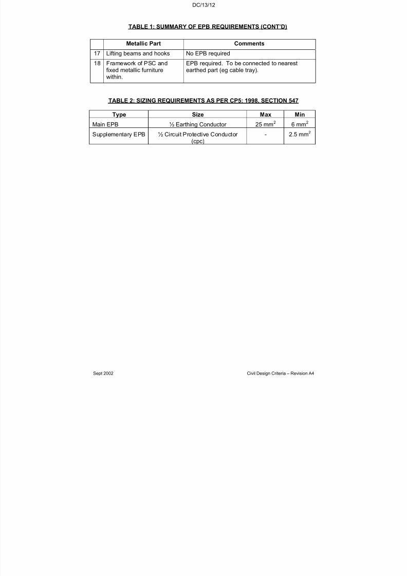
7/18/2019 LTA Civil_standards- Civil Design Criteria
http://slidepdf.com/reader/full/lta-civilstandards-civil-design-criteria 273/345
DC/13/12
Sept 2002 Civil Design Criteria – Revision A4
TABLE 1: SUMMARY OF EPB REQUIREMENTS (CONT’D)
Metallic Part Comments
17 Lifting beams and hooks No EPB required
18 Framework of PSC andfixed metallic furniture
within.
EPB required. To be connected to nearestearthed part (eg cable tray).
TABLE 2: SIZING REQUIREMENTS AS PER CP5: 1998, SECTION 547
Type Size Max Min
Main EPB ½ Earthing Conductor 25 mm2 6 mm2
Supplementary EPB ½ Circuit Protective Conductor (cpc)
- 2.5 mm2

7/18/2019 LTA Civil_standards- Civil Design Criteria
http://slidepdf.com/reader/full/lta-civilstandards-civil-design-criteria 274/345

7/18/2019 LTA Civil_standards- Civil Design Criteria
http://slidepdf.com/reader/full/lta-civilstandards-civil-design-criteria 275/345
DC/14/2
Sept 2002 Civil Design Criteria – Revision A4
14.1.3 Operating Modes
14.1.3.1 It is expected that the system will normally be running in open mode(drainage circuit not connected). When monitoring shows that straycurrents are excessive and remedial measures are unsuccessful,drainage mode will be employed.
14.1.3.2 The drainage mode will be set in operation by the Railway Operator byclosing the isolator in the drainage panel in the relevant tractionsubstation. Drainage mode will also be selected for testing.
14.2 SYSTEM REQUIREMENTS
14.2.1 Trackwork
14.2.1.1 The size of the running rails shall be UIC 60 to reduce voltage drop inthe running rails, which in turn will reduce leakage of stray current.
14.2.1.2 The minimum track to structure earth resistance under dry and dampconditions shall be 10 ohm-km before any equipment/cables areconnected. This is to be achieved by the following methods asappropriate:
(1) Insulating pad beneath rails(2) Insulation of rail fastenings(3) Insulating pad beneath base plate(4) Insulation system at level crossings and similar locations
14.2.1.3 The bottom face of running rails shall be at least 50 mm above the in-situ track concrete or ballast.
14.2.1.4 Guard rails on viaduct tracks shall be fixed on insulated fastenings.Guard rails shall be insulated from the running rails and include 20mmair gaps every 18 metres approximately.
14.2.1.5 Permanent IRJs shall be provided at locations close to tractionsubstations to segregate sections of track into electrically independentlengths.
14.2.2 Elevated MRT Stations and Viaducts (Fig. 14.1)
14.2.2.1 The control of leakage at source shall be by insulation of the runningrails as described in Clause 14.2.1 above.
14.2.2.2 Protection of viaducts against stray current corrosion shall also beprovided by a high electrical resistant waterproof membrane above thestructural concrete and below the ballast. The membrane shall beprotected by a concrete screed.
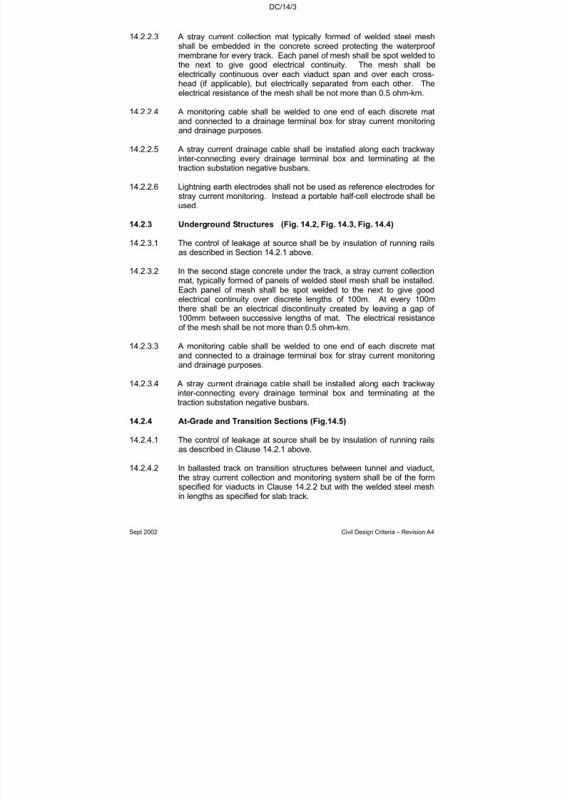
7/18/2019 LTA Civil_standards- Civil Design Criteria
http://slidepdf.com/reader/full/lta-civilstandards-civil-design-criteria 276/345
DC/14/3
Sept 2002 Civil Design Criteria – Revision A4
14.2.2.3 A stray current collection mat typically formed of welded steel meshshall be embedded in the concrete screed protecting the waterproof membrane for every track. Each panel of mesh shall be spot welded tothe next to give good electrical continuity. The mesh shall beelectrically continuous over each viaduct span and over each cross-head (if applicable), but electrically separated from each other. Theelectrical resistance of the mesh shall be not more than 0.5 ohm-km.
14.2.2.4 A monitoring cable shall be welded to one end of each discrete matand connected to a drainage terminal box for stray current monitoringand drainage purposes.
14.2.2.5 A stray current drainage cable shall be installed along each trackwayinter-connecting every drainage terminal box and terminating at thetraction substation negative busbars.
14.2.2.6 Lightning earth electrodes shall not be used as reference electrodes for stray current monitoring. Instead a portable half-cell electrode shall be
used.
14.2.3 Underground Structures (Fig. 14.2, Fig. 14.3, Fig. 14.4)
14.2.3.1 The control of leakage at source shall be by insulation of running railsas described in Section 14.2.1 above.
14.2.3.2 In the second stage concrete under the track, a stray current collectionmat, typically formed of panels of welded steel mesh shall be installed.Each panel of mesh shall be spot welded to the next to give goodelectrical continuity over discrete lengths of 100m. At every 100m
there shall be an electrical discontinuity created by leaving a gap of 100mm between successive lengths of mat. The electrical resistanceof the mesh shall be not more than 0.5 ohm-km.
14.2.3.3 A monitoring cable shall be welded to one end of each discrete matand connected to a drainage terminal box for stray current monitoringand drainage purposes.
14.2.3.4 A stray current drainage cable shall be installed along each trackwayinter-connecting every drainage terminal box and terminating at thetraction substation negative busbars.
14.2.4 At-Grade and Transition Sections (Fig.14.5)
14.2.4.1 The control of leakage at source shall be by insulation of running railsas described in Clause 14.2.1 above.
14.2.4.2 In ballasted track on transition structures between tunnel and viaduct,the stray current collection and monitoring system shall be of the formspecified for viaducts in Clause 14.2.2 but with the welded steel meshin lengths as specified for slab track.
7/18/2019 LTA Civil_standards- Civil Design Criteria
http://slidepdf.com/reader/full/lta-civilstandards-civil-design-criteria 277/345
DC/14/4
Sept 2002 Civil Design Criteria – Revision A4
14.2.4.3 For concreted track on transition structures between tunnel andviaduct, the stray current collection and monitoring system shall be of the form specified for underground structures in Clause 14.2.3.
14.2.4.4 No stray current drainage or monitoring provisions beyond thatdescribed Clause 14.2.1 is required for ballasted at-grade sections of railway.
14.2.4.5 No utility pipe or service shall be located under the at-grade sections of railway.
14.2.5 Depots
14.2.5.1 The control of leakage at source shall be by insulation of running railsas described in Section 14.2.1 above as far as practicable.
14.2.5.2 The depot area should be electrically isolated from the main line byusing permanent Insulated Rail Joints (IRJs) at appropriate locations.
Remote control facilities should be provided to enable each IRJ to bebypassed to allow transfer of traction power to or from the depot in theevent of substation power failure.
14.2.5.3 No monitoring or drainage system is required in the depot track areabeyond that specified above.
14.3 SYSTEM COMPONENTS
14.3.1 Cabling
14.3.1.1 For underground stations and tunnels, low smoke, halogen free, fireretardant type cables with armouring shall be provided.
14.3.1.2 For above ground station and viaducts, fire retardant type cables witharmouring shall be provided.
14.3.1.3 All cables shall have an insulation level of DC 2000 V and be singlecore, multi-stranded copper conductor and XLPE insulated .
14.3.1.4 Cable sizes shall be as follows:
(a) Monitoring cable (from mesh to terminal box) – 35mm
2
copper (b) Drainage cable (inter-connecting terminal boxes) – 185mm2
copper
14.3.1.5 The location of the drainage cable shall be co-ordinated with theelectrical services contractor.

7/18/2019 LTA Civil_standards- Civil Design Criteria
http://slidepdf.com/reader/full/lta-civilstandards-civil-design-criteria 278/345

7/18/2019 LTA Civil_standards- Civil Design Criteria
http://slidepdf.com/reader/full/lta-civilstandards-civil-design-criteria 279/345
DC/14/6
Sept 2002 Civil Design Criteria – Revision A4
14.4.2 Installations
14.4.2.1 Electrical insulation from the transit or depot structure is required for the following installations located along the trainway.
(a) Signalling equipment and/or their supports(b) Platform Screen Doors
(c) Blue light station support frames and siding telephone supportframes
(d) Metal pipes(e) Lightning protection system to viaducts(f) Earthing cables(g) Sectionalising switches, high-speed circuit breakers and their
supports(h) Control boxes, test boxes, junction boxes etc and/or their supports.
14.4.3 Elevated Stations and Viaducts
14.4.3.1 The waterproofing and insulation membrane between ballast andstructure concrete on the viaducts shall be a bonded system with
minimum electrical resistivity of 1 x 10¹¹ ohm-cm and thickness not less
than 2 mm.
14.4.3.2 Anchor bolts for viaduct bearings shall be isolated from the steelreinforcement in viaducts beams and cross-heads.
14.4.3.3 Any metallic handrail, fascia units, walkway and the like along theviaduct shall be electrically insulated from the steel reinforcement in
viaduct beams and cross-heads.
14.4.3.4 Steel reinforcement and anchor bolts in concrete precast units used asfascia or similar shall not be in contact with the steel reinforcement of the viaduct beams.
14.4.3.5 The material of rainwater downpipes in columns shall be non-conductive.
14.4.3.6 Lightning down conductor strip shall be fixed with proprietary insulatorsto avoid electrical contact with steel reinforcement in cross-heads and
columns.
14.4.3.7 An effective water drainage system shall be designed to preventponding of rainwater.
14.4.5 Underground Structures and Tunnels
14.4.5.1 Proper detailing shall be provided to prevent ponding of seepage water around track fastenings.

7/18/2019 LTA Civil_standards- Civil Design Criteria
http://slidepdf.com/reader/full/lta-civilstandards-civil-design-criteria 280/345
DC/14/7
Sept 2002 Civil Design Criteria – Revision A4
14.4.5.2 Handrails, walkways and other continuous metallic elements along thetrainway shall be electrically insulated from the structure.
14.4.5.3 Tunnel segments shall be electrically separated from each other acrossall circumferential joints.
14.4.5.4 All non-railway metallic service pipes passing through or embedded
within the MRT structure shall be insulated from the structure by aplastic sleeve.
14.5 SYSTEM TESTING AND MONITORING(refer to Fig. 14.6 to Fig. 14.9 and Appendix 2)
14.5.1 Track to Structure Earth and Water Earth Resistance
14.5.1.1 The track resistance against current leakage shall be measured withrespect to:
(1) structure earth by means of the terminals from the stray currentcorrosion control steel mesh.
(2) water earth by means of the earth connection in the substation.
14.5.1.2 The track to structural earth resistance measurements shall be taken atthe following two stages:
(1) For newly laid track before any power and signalling tracksideequipment and cabling are connected.
(2) For integrated track system when power and signallingtrackside equipment and cabling are connected.
14.5.1.3 As far as possible, different track support system shall be separatedelectrically for testing and monitoring:
(1) Main line shall be separated from the depot tracks.
(2) Tracks on viaducts shall be separated from those on at-gradesections, transition sections or inside tunnels.
14.5.2 Stray Voltage Level Monitoring
14.5.2.1 The stray voltage level monitoring shall involve measuring the steelmesh potential with respect to a portable half-cell electrode.
14.5.3 Substation Drainage Current Measurements
14.5.3.1 Provision shall be made to facilitate the following measurements:
(a) Traction current at output of rectifier
7/18/2019 LTA Civil_standards- Civil Design Criteria
http://slidepdf.com/reader/full/lta-civilstandards-civil-design-criteria 281/345
DC/14/8
Sept 2002 Civil Design Criteria – Revision A4
(b) Negative busbar to earth voltage
(c) Drainage current distribution and total drainagecurrent.
14.5.3.2 These measurements will be taken at traction substations to check the
system balance and to provide a basis for comparison of potentials.
14.5.4 Other Tests
14.5.4.1 In addition to the above, the following tests shall be performed:
(a) Track to steel mesh resistance measurements
(b) Electrical continuity test of steel mesh
(c) Commissioning tests for reference electrodes
(d) Insulation test for insulated installations.
14.5 5 Test Procedures
14.5.5.1 The types, methods and procedures of all tests and measurementsincluding the format for recording the test results shall be submitted tothe Engineer for acceptance.
14.5.5.2 Effective fault finding methods shall be incorporated and the technicalspecifications of instruments and equipment used to locate stray
current leakage paths shall be specified.
14.5.5.3 All rail potential measurements as well as all traction and drainagecurrent measurements shall be taken over a 24-hour period during trialrunning to enable both the traction peaks and non-traction naturalpotential to be observed and recorded.
14.5.5.4 All test instruments and measurement charts are to be provided by thecommissioning party.
14.5.5.5 Upon completion of a commissioning test, a Test Inspection Certificate
shall be endorsed and submitted by the Registered ProfessionalEngineer of the relevant contractor to the Engineer for acceptance.
14.5.5.6 All test programmes shall, unless otherwise specified, be submitted tothe Engineer at least four weeks before the tests start.
7/18/2019 LTA Civil_standards- Civil Design Criteria
http://slidepdf.com/reader/full/lta-civilstandards-civil-design-criteria 282/345
DC/14/9
Sept 2002
Appendix 1 : Stray Current Corrosion Control Requirements - Installation
Serialno.
Items Undergroundtunnel and station
Viaduct/ AtGrade
Dep
1 Welded steel mesh to be installed under the track. Externalconnecting terminals to be provided. a a NA
2 Monitoring cable from steel mesh reinforcement to the drainageterminal boxes to be provided. (see Fig. 14.6 and Fig.14.10) a a NA
3 Drainage terminal boxes and drainage cables interconnectingdrainage terminal boxes to be installed along tunnel wall or viaducts.(see Fig. 14.6)
a a NA
4 Drainage cable from appropriate drainage terminals inside drainageterminal boxes to the drainage panel in the traction substation (seeFig. 14.6)
a a NA
5 Installation of stray current drainage units and all associatedaccessories at traction substations. a a NA
6 Installation of cable bracket/ tray to hold main drainage cable. a a NA
7 Reference electrodes a (at stations only) NA NA
8 Provision of insulating sleeves for all non-railway metallic servicepipes passing through the railway structure a a a
9 Running rails to be insulated by the following methods asappropriate:a) Insulating pad beneath railsb) Insulation of rail fasteningsc) Insulation beneath base plated) At level crossings and similar locations
a a a

7/18/2019 LTA Civil_standards- Civil Design Criteria
http://slidepdf.com/reader/full/lta-civilstandards-civil-design-criteria 283/345
DC/14/10
Sept 2002
Serialno.
Items Underground tunneland station
Viaduct/ AtGrade
Dep
10 Bottom face of running rail shall be at least 50mm above the in-situtrack concrete or ballast. a a a
11 Depot electrically isolated from the main line system by using:
a) permanent IRJs (Insulated rail joints) at appropriate locationson reception tracks
b) third rail sectionalising adjacent to IRJs for segregation
c) third rail and running rail sectionalising switches andassociated works with remote control facilities.
NA NA a
12 Lightning down conductor strip to be fixed with proprietaryinsulator. NA a NA
13 Insulation of the following installation from the transit structure or depot structure:
a) Signalling equipment and/or their supports
b) Platform screen doors
c) Blue light station and siding telephone supports
d) Dry riser pipe
e) Pumping mains, drainage pipes, and other piped servicesprovided by the civil contractor
f) Earthing cables
g) Sectionalising switches, circuit breakers, control/ test/ junctionboxes, etc
a
a
a
a
a
a
a
a
NA
a
a
a
a
a
a
NA
a
a
a
a
a

7/18/2019 LTA Civil_standards- Civil Design Criteria
http://slidepdf.com/reader/full/lta-civilstandards-civil-design-criteria 284/345
DC/14/11
Sept 2002
Appendix 2 : Stray Current Corrosion Control Requirements – Testing and Commissioning
Serialno.
Commissioning Tests Commissioning Test tobe carried out by *
1 Commissioning test for reference electrodes C At stations only
2 Electrical continuity test of welded reinforcement mesh
(Electrical resistance shall not be more than 0.5 Ω-km)
TW Measurements
3 Track to structure earth resistance measurements
(Pass Criterion shall not be less than 10 Ω-km)
TW Measurementsbefore the insta
(Refer to TableRequirements Specification)
4 Track to structure earth resistance measurements for integrated tracksystem
(Pass Criterion shall not be less than 7.5 Ω-km)
TW
PS, SE
Measurementsequipment andTW shall be res
(Refer to TableRequirements Specification)
PS, SE shall comeasurements
PS, SE shall becleaning, discocables for TW t
5 Test on all insulation under Appendix 1, Item 13 C, TW, SE, ES, PS Individual contrrecords to confadequate insul

7/18/2019 LTA Civil_standards- Civil Design Criteria
http://slidepdf.com/reader/full/lta-civilstandards-civil-design-criteria 285/345
DC/14/12
Sept 2002
Serialno.
Commissioning Tests Commissioning Test tobe carried out by *
6 Stray current measurement in traction substation:
a) traction current at output of rectifier b) negative busbar to earth voltage (rail potential)c) drainage current
TW, PS24-hr measurePS is to assist
7 Stray voltage level measurement with respect to reference electrodes/half cell electrodes for steel mesh (via monitoring cable)
TW 24-hr measureMeasurement rExtent of testin
* Key to Appendix 1 and 2:
NA = Not ApplicableC = Civil contractor TW = Trackwork contractor SE = Signalling Equipment and Platform Screen Door contractor PS = Power Supply Equipment and Cabling contractor ES = Electrical Services contractor MS = Mechanical Services contractor CS = Communication System contractor
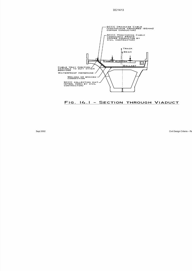
7/18/2019 LTA Civil_standards- Civil Design Criteria
http://slidepdf.com/reader/full/lta-civilstandards-civil-design-criteria 286/345
DC/14/13
Sept 2002
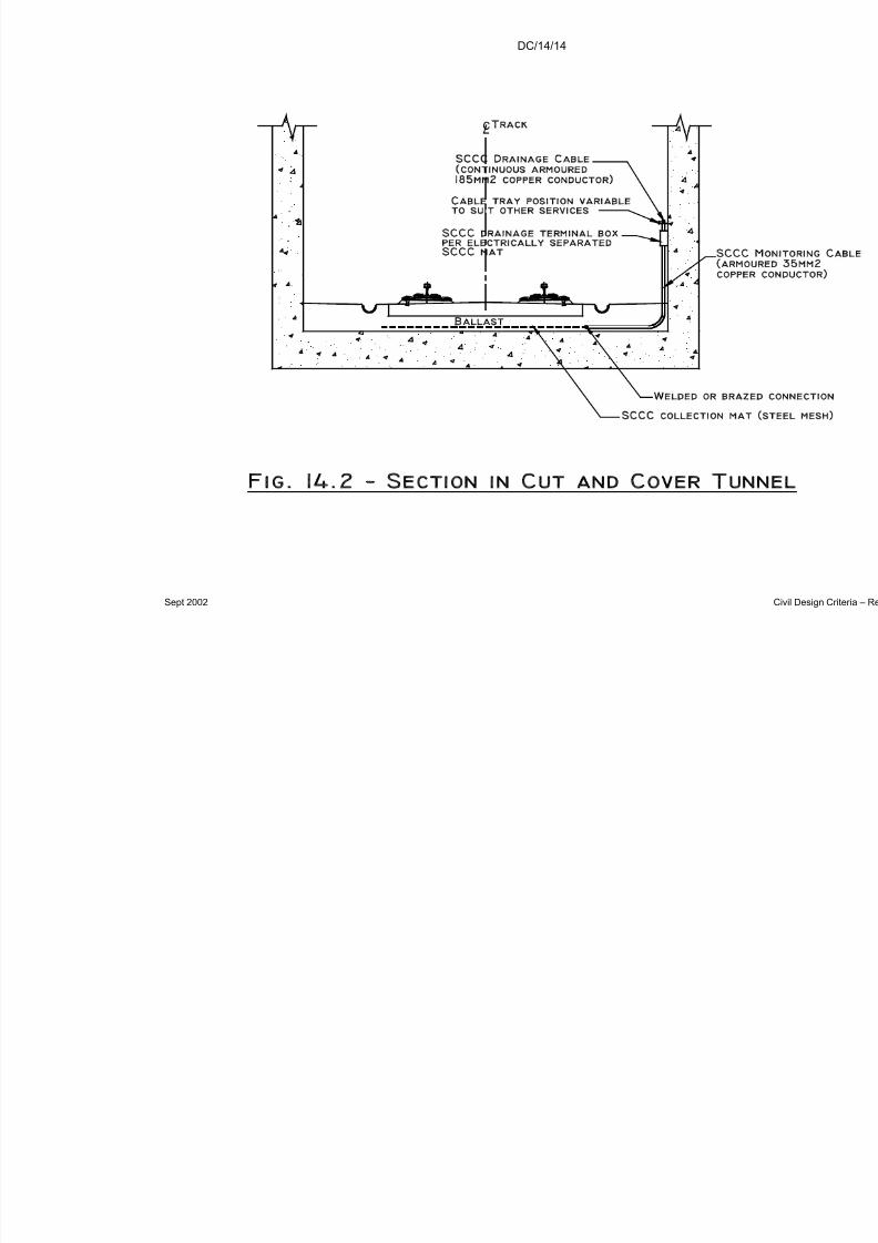
7/18/2019 LTA Civil_standards- Civil Design Criteria
http://slidepdf.com/reader/full/lta-civilstandards-civil-design-criteria 287/345

7/18/2019 LTA Civil_standards- Civil Design Criteria
http://slidepdf.com/reader/full/lta-civilstandards-civil-design-criteria 288/345
DC/14/15
Sept 2002

7/18/2019 LTA Civil_standards- Civil Design Criteria
http://slidepdf.com/reader/full/lta-civilstandards-civil-design-criteria 289/345
DC/14/16
Sept 2002
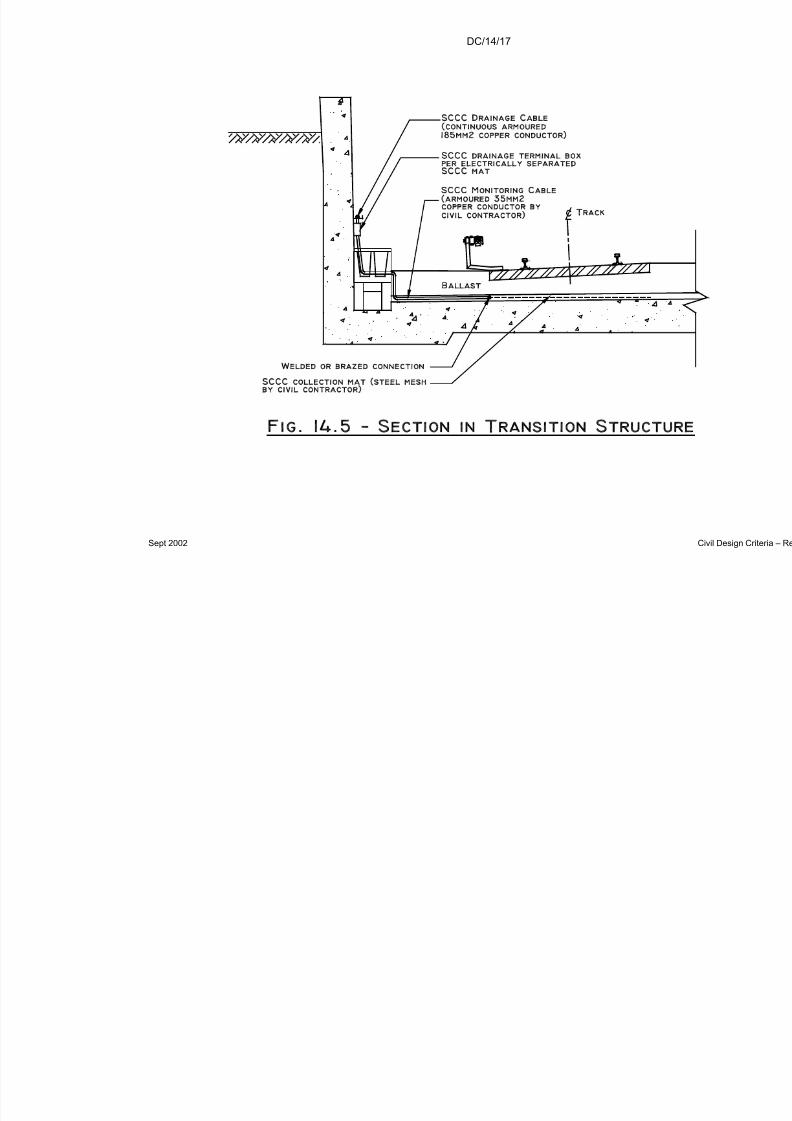
7/18/2019 LTA Civil_standards- Civil Design Criteria
http://slidepdf.com/reader/full/lta-civilstandards-civil-design-criteria 290/345
DC/14/17
Sept 2002
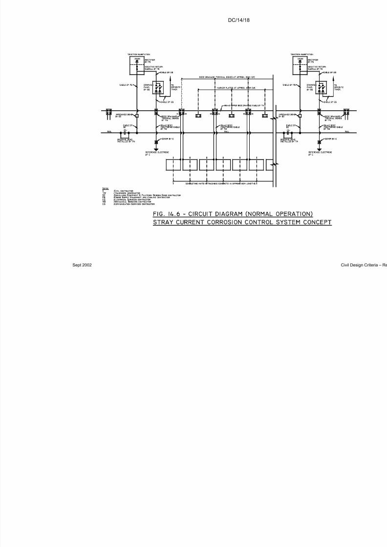
7/18/2019 LTA Civil_standards- Civil Design Criteria
http://slidepdf.com/reader/full/lta-civilstandards-civil-design-criteria 291/345
DC/14/18
Sept 2002
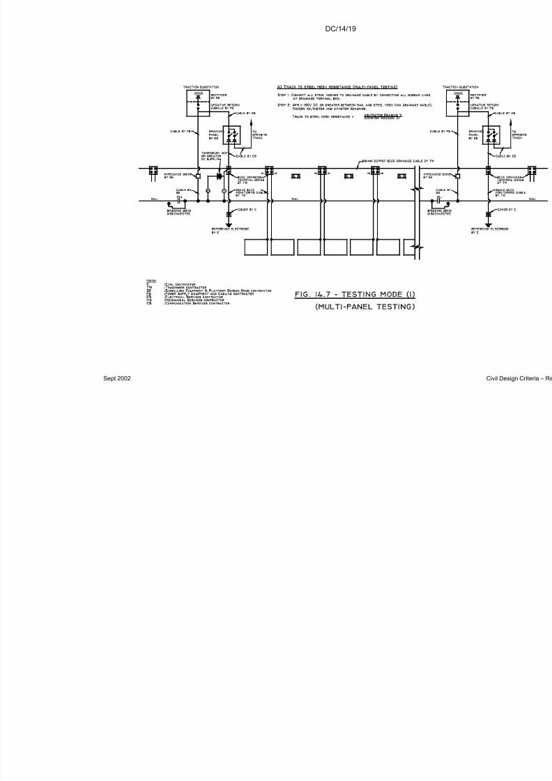
7/18/2019 LTA Civil_standards- Civil Design Criteria
http://slidepdf.com/reader/full/lta-civilstandards-civil-design-criteria 292/345
DC/14/19
Sept 2002

7/18/2019 LTA Civil_standards- Civil Design Criteria
http://slidepdf.com/reader/full/lta-civilstandards-civil-design-criteria 293/345
DC/14/20
Sept 2002

7/18/2019 LTA Civil_standards- Civil Design Criteria
http://slidepdf.com/reader/full/lta-civilstandards-civil-design-criteria 294/345
DC/14/21
Sept 2002
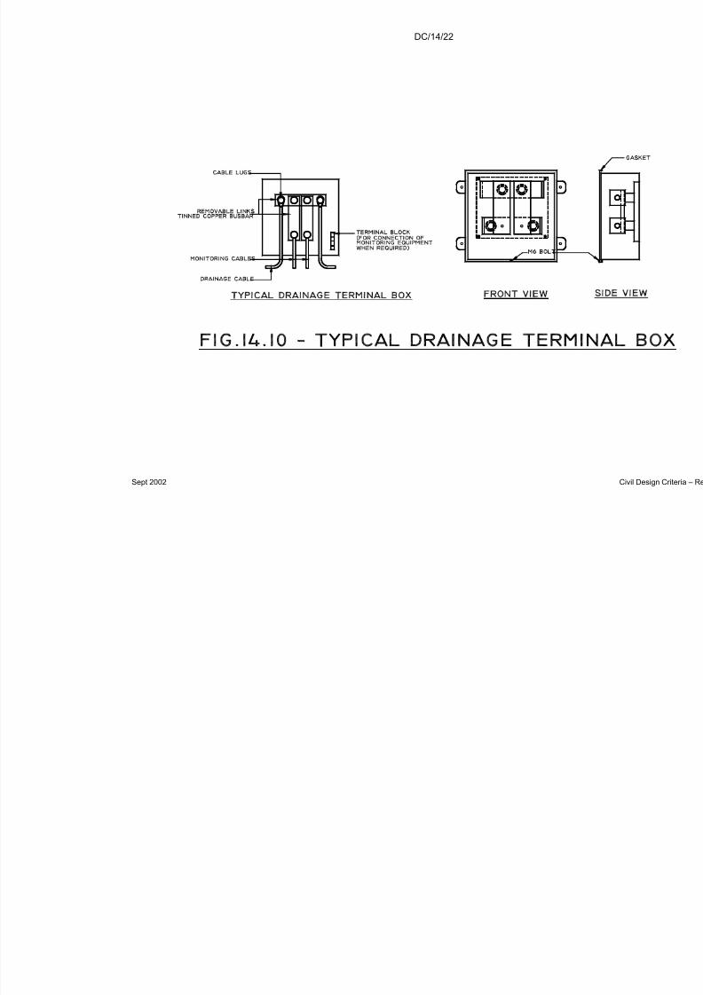
7/18/2019 LTA Civil_standards- Civil Design Criteria
http://slidepdf.com/reader/full/lta-civilstandards-civil-design-criteria 295/345
DC/14/22
Sept 2002

7/18/2019 LTA Civil_standards- Civil Design Criteria
http://slidepdf.com/reader/full/lta-civilstandards-civil-design-criteria 296/345
DC/15/1
Sept 2002 Civil Design Criteria – Revision A4
CHAPTER 15
NOT USED

7/18/2019 LTA Civil_standards- Civil Design Criteria
http://slidepdf.com/reader/full/lta-civilstandards-civil-design-criteria 297/345
DC/16/1
Sept 2002 Civil Design Criteria – Revision A4
CHAPTER 16
NOT USED

7/18/2019 LTA Civil_standards- Civil Design Criteria
http://slidepdf.com/reader/full/lta-civilstandards-civil-design-criteria 298/345
DC/17/1
Sept 2002 Civil Design Criteria – Revision A4
CHAPTER 17
NOT USED

7/18/2019 LTA Civil_standards- Civil Design Criteria
http://slidepdf.com/reader/full/lta-civilstandards-civil-design-criteria 299/345
DC/18/1
Sept 2002 Civil Design Criteria – Revision A4
CHAPTER 18
AUTOMATIC AND MANUAL IRRIGATION SYSTEM
18.1 REGULATIONS, CODES AND STANDARDS
The design, manufacture, supply, installation, testing andcommissioning of Automatic and Manual Irrigation Systems shall begoverned by all applicable local codes of practice, regulations,standards and requirements issued by all local government andstatutory authorities, agencies and service providers which shallinclude but not limited to the following:-
(a) Building Control Authority BCA(b) Ministry of the Environment ENV(c) Productivity and Standards Board PSB(d) PowerGrid Pte Ltd PowerGrid
(e) National Parks Board Nparks
18.2 AUTOMATIC IRRIGATION SYSTEM DESCRIPTION
The Automatic Irrigation System applies to viaduct and vehicular underpass.
The system is designed to provide irrigation on every planted strip.Pond water is transferred from mobile water tankers to theunderground storage tank by means of a coupling inlet and then used
for irrigation via pumpsets and a common main reticulation pipework.
18.3 DESIGN CRITERIA
18.3.1 The systems shall normally operate automatically without the need for manual intervention. Provisions shall however be made for manual andsemi-automatic operation mode. In addition, the systems shall haveprovision for remote monitoring of vital status.
18.3.2 Sprinkler and stream bubblers shall be provided.
18.3.3 The systems shall be provided to irrigate the landscape areas within thesite. The irrigation for the site comprises more than one independentsystems. Each system shall be functionally complete but not to be limitedto pumpsets, control valves, primary water filter, irrigation controller,pipework, etc. The design shall be developed in accordance with thefollowing parameters:
7/18/2019 LTA Civil_standards- Civil Design Criteria
http://slidepdf.com/reader/full/lta-civilstandards-civil-design-criteria 300/345
DC/18/2
Sept 2002 Civil Design Criteria – Revision A4
(a) Source of water : Raw Pond water transported by mobilewater wagon with a capacity 9000 litres.
(b) Sunken storagetank
: A sunken concrete storage tank with 3 daysstorage capacity for raw pond water shall beprovided by Builders. The tank shall bedesigned to house submersible pumpsets
with associated valves, fittings etc.
(c) Water demand : 5 litres per sq. m per day
(d) Watering cycle : Once per day (excluding rainy days)
(e) Watering time : Between 5 to 10 minutes per lot of sprinklers.
(f) Flow velocity : Flow along pipe shall be between 1 m/s to 3m/s
(g) No. of lots of sprinklers
: Each lot shall comprise sprinklers withapproximate equal flow rates and meetingthe power supply provided for the system.
(h) Position of Pipe : Pipes shall be positioned aesthetically, if necessary hidden in risers, and acceptableto the SO. Where possible, laying of pipeacross road shall be avoided.
(i) Power supply : An OG box, 3 phase/400 Volt
18.4 MICROPROCESSOR BASED IRRIGATION CONTROLLER
Microprocessor-based irrigation controller shall be provided to performall the operational control, status and fault indications. Details shall besubmitted for acceptance to National Parks Board and the Authority.
18.5 RAIN SHUT-DOWN
The control system shall provide for shut-down of the entire or part of theirrigation system if sufficient rainfall have occurred resulting in no irrigationrequired. Rainwater sensors/switches detecting rainfall shall be placed instrategic locations. Provision to override the rain shutdown signal shallalso be provided. The irrigation schedule shall resume after the "rain-shutdown" signals are cancelled. Provision for lamp indicator for "Rain-shutdown" ON/OFF status shall be provided in the control panel.

7/18/2019 LTA Civil_standards- Civil Design Criteria
http://slidepdf.com/reader/full/lta-civilstandards-civil-design-criteria 301/345
7/18/2019 LTA Civil_standards- Civil Design Criteria
http://slidepdf.com/reader/full/lta-civilstandards-civil-design-criteria 302/345
DC/18/4
Sept 2002 Civil Design Criteria – Revision A4
determined level. The light should automatically go off when the water level drops below this level.
18.9 SPRINKLER HEAD AND STREAM BUBBLER
18.9.1 The sprinkler head shall be used in the automatic irrigation of landscaping
areas as required by National Parks Board. It shall produce a fine sprayof water of even distribution over the entire area of coverage. Lowprecipitation irrigation sprinklers are preferred. Each pop-up body shallhave a captioned filter screen and a wiper seal.
18.9.2 The stream bubbler shall be used in manual and automatic irrigation of landscaping areas and flower troughs (except for pedestrian overheadbridges) as required by National Parks Board.
18.9.3 The sprinkler head and stream bubbler shall be constructed of UV-resistant plastic and corrosion resistant stainless steel parts of 304 or
316.
18.9.4 The bubblers shall provide consistent and precise flow rate compensatesfor pressure variation caused by terrain elevation or friction loss.
18.9.5 The operation of the sprinklers and the stream bubblers shall be vibrationfree and shall not produce any back splash.
18.10 PIPES AND FITTINGS
a) The main underground pipeline shall be heavy duty UPVC type.The lateral underground pipe shall be high density Polyethene type.For exposed areas, external piping using hot-dipped galvanised pipeshall be used.
b) Galvanised steel pipe sleeves shall be provided where pipes passthrough walls or run under road. There shall be a minimum of 20mmtotal space clearance between pipe outside diameter (OD) andsleeve inside diameter (ID). The space caulked with a soft non-setting waterproof mastic compound to give airtight seal.
c) Ductile iron pipes shall be used at the pump discharge to the mainvalve chamber before the main pipeline connection.
18.11 MANUAL IRRIGATION SYSTEM DESCRIPTION
18.11.1 The manual irrigation system applies to road bridge and pedestrianoverhead bridge.
18.11.2 The manual irrigation system shall be designed to carry water from thebase of the bridge to the planter troughs.

7/18/2019 LTA Civil_standards- Civil Design Criteria
http://slidepdf.com/reader/full/lta-civilstandards-civil-design-criteria 303/345
DC/18/5
Sept 2002 Civil Design Criteria – Revision A4
18.11.3 Water is distributed evenly to each planter trough
18.11.4 The water pipe shall be fixed to the inner wall of the trough that abut theplatform and above the soil level.
18.12 DESIGN CRITERIA
18.12.1 Pedestrian Overhead Bridge (POB)
a) One coupling inlet of diameter 25mm shall be provided at 1mground level for connection by the National Parks water tanker.The inlet shall be easily and safely accessible by the tanker.
b) The water pipe shall be made of stainless steel with 5mmdiameter holes provided at 200mm centre to centre along thebottom of the pipe.
18.12.2 Road Bridge
a) A coupling inlet shall be provided on both side of the trough at 1mabove ground level.
b) The water shall be distributed by suitably sized stream bubblersevenly spaced along the stainless steel pipe.
18.13 PIPES AND FITTINGS
18.13.1 Stainless Steel Pipes and Fittings
Stainless steel pipes and fittings shall conform to BS4127: Part 2 .
18.13.2 Pipe Supports
a) All steel hangers, supports, anchors, bolts, nuts, washers shall behot-dipped galvanised.
b) Supports shall be provided at spacing not exceeding the valuesspecified in the table below unless otherwise indicated:-
MATERIAL OF PIPE DIAMETER OF
PIPE IN MM
MAX. SPACING OF SUPPORTS
HORZ. RUN IN M OR VERT. RUN IN M
Stainless Steel Pipe 20 - 25 2.5
32 - 50 3.5

7/18/2019 LTA Civil_standards- Civil Design Criteria
http://slidepdf.com/reader/full/lta-civilstandards-civil-design-criteria 304/345
DC/18/6
Sept 2002 Civil Design Criteria – Revision A4
18.13.3 Pipe Sleeves
a) Galvanised steel pipe sleeves shall be provided where pipes passthrough walls or run under road. There shall be a minimum of 20mm total space clearance between pipe outside diameter (OD)and sleeve inside diameter (ID). The space caulked with a softnon-setting waterproof mastic compound to give airtight seal.
b) Puddle flanges cast in wall shall be used when water-tightness isrequirement.
18.14 PIPE INSTALLATION
18.14.1 All pipes shall be rigidly anchored and supported with hangers andsupports. Each length of pipe and each fitting shall be thoroughly cleanedout before installing.
18.14.2 Pipework shall be provided with sufficient flexible coupling for all forcesand movements in the completed system and shall provide sufficientdetachable couplings for complete and easy dismantling duringmaintenance, and assembly during construction.
18.14.3 Any open ended pipe or pipe connection left overnight or for anyconsiderable period shall be protected from the entry of dirt, sand, etc bythe fixing of approved plastic or galvanised iron sheet cap securely held.
18.14.4 All exposed pipework shall be installed so that sufficient clearance is leftbetween the outside of the pipe and the nearest wall, and approximately
75mm from ceiling or slab. Pipe joints or fittings will not be permittedwithin the thickness of walls, floors any partitions or below a beam.
18.14.5 Pipework shall be installed with correct falls gradient to ensure adequatedraining.
18.14.6 A gasket, conforming to ANSI B16.21 and ASTM D2000, shall beinstalled between clamp and pipe or dissimilar materials.
18.14.7 All pipe works shall be bonded to the lightning protection system.
18.15 OTHER ACCESSORIES
18.15.1 Primary Filters
The water filters shall be used when sprinklers and bubblers are used.The filters shall be corrosion – proof with filter housing made of stainless316. It shall be easily access and clean by flushing with water.

7/18/2019 LTA Civil_standards- Civil Design Criteria
http://slidepdf.com/reader/full/lta-civilstandards-civil-design-criteria 305/345
DC/19/1
Sept 2002 Civil Design Criteria – Revision A4
CHAPTER 19
INSTRUMENTATION
19.1 INTRODUCTION
This Chapter covers the Authority’s requirements for the design andselection of instrumentation for the monitoring of movements, stresses,strains, piezometric pressures and vibrations due to excavations andtunnelling, and of the permanent works.
The Building Control Authority and other regulatory bodies also requirethe installation and monitoring of instruments for excavations,tunnelling, piling and other construction work. Compliance with thisChapter may not be sufficient to fully satisfy these regulatory bodies.The Contractor shall install both the instrumentation required under thissection and any additional instrumentation required to satisfy the
regulatory bodies.
19.2 INSTRUMENTATION REQUIREMENTS
The instrumentation shall be designed and selected to:
a) Verify the assumptions made in the design.b) Provide confirmation of the predicted behaviour of the support
system during excavation or tunnelling.c) Assess the effects of the work on buildings, utilities and other
structures.d) Provide sufficient information to determine how and why thework is affecting buildings, structures and utilities.
e) Provide a record of performance.f) Enable construction to be carried out safely and soundly at
every stage.g) Where required, enable appropriate contingency measures to be
implemented in time.
In order to meet these requirements the instrumentation, design shallinclude the minimum monitoring specified herein plus such additional
instrumentation as is necessary to meet the requirements given above.
19.3 MONITORING PLANS AND RELATED DOCUMENTS
The Contractor shall prepare and maintain a Monitoring Plancomprising but not limited to the following:

7/18/2019 LTA Civil_standards- Civil Design Criteria
http://slidepdf.com/reader/full/lta-civilstandards-civil-design-criteria 306/345
DC/19/2
Sept 2002 Civil Design Criteria – Revision A4
19.3.1 Monitoring Drawings
Monitoring drawings shall be prepared at a scale not greater than1:500 clearly indicating the location and installation height/depth of allinstrumentation. All instruments shall be clearly identified in a uniquealpha-numeric sequence using the instrumentation nomenclature asdefined for use in the LTA’s Geotechnical Data Base. Each drawing
shall show all of the instrumentation to be installed within the areacovered by the drawing. At contract boundaries, the instrumentation tobe installed by the adjacent contractor shall be shown.
Where multi-sensor instruments are used the Contractor shall clearlyidentify the reduced level and/or direction of each individual sensor,such information is to be provided either on the drawings or in separatetables.
Where buildings, structures or services subject to special protectionmeasures are encountered the Contractor shall prepare a detailed
drawing of each individual building, structure or service indicating theexact location of all monitoring points, including the reduced level of theproposed instrument. Sections shall also be prepared identifying clearlythe extent of any existing features, cracks etc, requiring monitoring.Where possible the structural layout of the building shall also beindicted on these drawings.
All drawings for buildings, structures or services subject to specialprotection measures shall be prepared at a scale not greater that 1:50except where prior approval has been granted by the Authority.
19.3.2 Instrumentation Tables
Instrumentation tables shall be prepared which should include, but notbe limited to, the following information for each instrument:
• Instrument type
• Unique instrument number
• Sensor number
• Proposed Easting
• Proposed Northing
• Proposed Reduced Level of all sensors
• Proposed reading frequency during key stages of the works• Review levels for all sensors (see Clause 19.8)
19.3.3 Instrumentation Specifications
The design shall include the preparation of InstrumentationSpecifications including: installation procedures, fixing methods, groutmixes, protection measures and such other details that are necessaryto ensure that the instrumentation is capable of meeting the requiredaccuracy.
7/18/2019 LTA Civil_standards- Civil Design Criteria
http://slidepdf.com/reader/full/lta-civilstandards-civil-design-criteria 307/345
DC/19/3
Sept 2002 Civil Design Criteria – Revision A4
19.4 MINIMUM MONITORING
All excavations in excess of 4.5m deep (from commencing level) and alltunnels shall include a minimum level of monitoring, as specified below.
The monitoring shall extend along the full length of the work, and for at
least 50m beyond the contract boundaries.
19.4.1 Minimum Monitoring for Excavations
All excavations shall include Type A, B and C monitoring arrays, asshown in Figures 19.3 and 19.5, on the following basis:
a) One Type A, B or C array for every 25m of perimeter wall or slope.
b) An average of one Type B or C array for every 100m of perimeter wall or slope.
c) An average of one Type C array for every 500m of perimeter wall or slope.
The distances (quoted above) used to assess the number of monitoringarrays shall be taken as the plan distance around the perimeter of theexcavation measured at the top of the slope or retaining wall. Thenumber of arrays required shall be rounded to the nearest wholenumber. If an excavation is being carried out in a number of adjacentsections or cells, then the perimeter shall be taken as the distancearound all of the adjacent sections or cells, ignoring intermediate crosswalls.
The designer shall locate the Type B and C arrays in areas of particular concern, taking into account the nature and sequence of construction,the presence of adjacent buildings and the assessed groundconditions. The Types B and C arrays are not required to be evenlyspaced.
Where there is any portion of the Works which:
• is over 150m in length (measured along the centre line of the tracks),continuous, and
• there are no buildings or utilities within the monitoring zone
then the minimum number of monitoring arrays required over thatportion of the Works can be reduced by reducing the requirement for Type B and C arrays to one half of that defined above, and, for unsupported excavations only, the Type A arrays can be omitted.
19.4.2 Minimum Monitoring for Tunnels
Type D, E and F arrays shall be provided for tunnelling (including pipe jacking), as shown in Figures 19.6 and 19.7, on the following basis:

7/18/2019 LTA Civil_standards- Civil Design Criteria
http://slidepdf.com/reader/full/lta-civilstandards-civil-design-criteria 308/345
DC/19/4
Sept 2002 Civil Design Criteria – Revision A4
a) One of Type D, E or F every 25m of twin tunnel.b) One of Type E or F for every 200m of twin tunnel, on average.c) One of Type F for every 1000m of twin tunnel, where the tunnels
have an excavated diameter in excess of 3m.
Type F arrays need not be provided where the tunnels have anexcavated diameter equal to or less than 3m.
The distance shall be measured along the centre line of the tunnelsand shall be based on the total length of tunnelling required under thecontract. The number of arrays required shall be rounded to thenearest whole number.
Where single or multiple tunnels are constructed, the number of arraysshall be the same as if twin tunnels were being constructed. However,the number of monitoring instruments in each array shall be changed(reduced for single tunnels, increased for multiple parallel tunnels) toprovide the same level of monitoring for each of the tunnels as for the
twin tunnels.
The designer shall locate the Type E and F arrays in areas of particular concern, taking into account the nature and sequence of construction,the presence of adjacent buildings and the assessed groundconditions. Type E and F arrays should be particularly located in areaswhere it is expected that the tunnel will encounter soils of the KallangFormation. The Types E and F arrays are not required to be evenlyspaced.
Where there is any portion of the works which:
• is over 150m in length (measured along the centre line of thetracks), continuous, andthere are no buildings or utilities within the monitoring zonethen the minimum number of monitoring arrays required over thatportion of the works can be reduced to one half of that definedabove.
19.4.3 Minimum Monitoring of Struts and Ground Anchors
At least 15% of all struts and ground anchors shall be monitored for load using strain gauges and/or load cells. At least 25% of the struts
and anchors monitored using strain gauges shall also be monitoredusing load cells. Where strain gauges are used, a minimum of 2 straingauges coupled with temperature monitoring shall be installed at eachmonitoring location, as shown in Figure 19.4.
As far as possible, the strut and anchor monitoring locations should beselected so that:
• every strut/anchor level at the selected locations is monitored;and
• the strut/anchor monitoring location coincides with a Type B or Cmonitoring array.
7/18/2019 LTA Civil_standards- Civil Design Criteria
http://slidepdf.com/reader/full/lta-civilstandards-civil-design-criteria 309/345
DC/19/5
Sept 2002 Civil Design Criteria – Revision A4
19.4.4 Minimum Monitoring of Buildings and Structures
All corners of buildings and structures, where any part of thereof fallswithin the monitoring zones defined in Figure 19.1, shall be monitoredby precise levelling.
Tensile strains shall be monitored by extensometers or by opticalsurvey for all buildings with predicted tensile strain greater than 0.1%and for any building subject to protection measures.
Crack monitoring shall be carried out for existing cracks and newcracks occurring during the works, and on movement joints.
19.4.5 Minimum Monitoring of Utilities
All gas, water and sewer pipes within the monitoring zone defined inFigure 19.2 shall be monitored with settlement points placed onto or
just above the utility, at intervals of not less than 25m. Typically,utilities that are less than 4m below ground level should be monitoredwith points on the utility, while utilities more than 4m below ground levelcan be monitored with points placed 2m above the utility. Joints inelectrical cables with voltage higher than 22kV and in fibre opticalsystems shall be monitored for movement across the joint.
19.4.6 Minimum Monitoring for Areas of Ground Treatment
A grid of surface points to monitor heave or settlement shall beestablished over any area of ground treatment. The spacing between
points in both directions shall not be more than 5m. This grid shallextend at least 10m beyond the edges of the ground treatment zone.
19.4.7 Minimum Monitoring for Tunnelling Under Buildings
Where any part of the tunnel is directly below any part of a building, thefollowing shall be implemented as a minimum:
a) A comprehensively monitored test zone shall be set up withinthe area 50m before the tunnel reaches the building. The testzone is required to confirm that the tunnelling is being carried
out in such a way that the settlements are less than or equal tothat expected from the design. The zone shall include at leasttwo type E arrays.
b) The building shall be considered as a structure subject toprotective works and instrumented on that basis.
c) While the instruments in the test zone and on the building arewithin 25m (in plan) of the location of the face of the tunnel, theyshall be read and the information assessed by the Contractor atleast once per ring of advance or once per three hours,whichever is more frequent.
7/18/2019 LTA Civil_standards- Civil Design Criteria
http://slidepdf.com/reader/full/lta-civilstandards-civil-design-criteria 310/345
DC/19/6
Sept 2002 Civil Design Criteria – Revision A4
d) There shall be a direct communication channel between thetunnel and the engineer assessing the results of the monitoring.
19.4.8 Minimum Monitoring for Buildings Subject to Protective Measures
Where a building or structure is subject to protective works, the buildingor structure shall be monitored using electrolevel beam systems, with a
back up system of precise levelling pins at both ends of each beam.
19.4.9 Minimum Vibration Monitoring
Vibration monitoring shall be carried out on all buildings adjacent topiling works.
Vibration monitoring shall be carried out where the construction activityinvolves processes which are likely to result in significant vibrations (for example: blasting) and where the vibration could adversely affectadjacent buildings, structures, utilities or equipment.
Some buildings, structures, utilities or equipment are particularlysensitive to vibration (for example: laboratories, hospitals). Vibrationmonitoring shall be carried out continuously where any constructionactivity is carried out near to sensitive buildings, structures, utilities or equipment, and the existing MRT system.
19.5 ADDITIONAL MONITORING
19.5.1 The design shall include additional instrumentation to augment the
minimum instrumentation specified above. The full instrumentationscheme (i.e., the minimum plus the additional) shall be sufficient tocomply with the instrumentation requirements given in 19.2 above.
19.6 READING FREQUENCY FOR MONITORING INSTRUMENTS
19.6.1 The design shall include tables giving reading frequencies for allinstruments. The frequency of reading the instruments may be varied,depending on the type of instrument and the relationship between theinstrument and areas of current activity. Criteria for increasing the
frequency of reading shall also be given.
19.6.2 Critical instrumentation shall be connected to data logging equipmentand the data shall be continuously accessible on computers in theEngineer’s site office. The data loggers, computers, cabling or other links and the necessary software to view the data in the Engineer’soffice shall form part of the instrumentation system to be provided by theContractor .

7/18/2019 LTA Civil_standards- Civil Design Criteria
http://slidepdf.com/reader/full/lta-civilstandards-civil-design-criteria 311/345
DC/19/7
Sept 2002 Civil Design Criteria – Revision A4
The following shall be considered as ‘critical’ instrumentation:
a) All strut and anchor monitoring instruments.b) All monitoring instruments on, or adjacent to, buildings subject to
protection measures.c) Piezometers installed to monitor the effects of bored tunnelling,
and where the tip of the piezometer is in soils of the Kallang or
Tekong formation.d) Pressure cells, strain gauges or other instrumentation installed
to confirm the design loads in tunnel linings or treated ground.e) Monitoring of joints in cables with voltage higher than 22kVa and
joints in fibre optic cables.f) Vibration monitoring where any construction activity is carried
out near to sensitive buildings, structures, utilities or equipment.g) Any other instrumentation where continuous monitoring is
necessary to ensure the safety of the works and of adjacentbuildings, structures and utilities, and of all personnel includingthe workforce.
19.7 ACCURACY AND RANGE OF MONITORING INSTRUMENTS
19.7.1 The accuracy and reading range of all of the monitoring instrumentsshall be specified as part of the design.
19.7.2 All readout units and survey equipment used for monitoring shall becapable of storing the data digitally, and have the facility to be directlyconnected to a computer for the downloading of the data.
19.7.3 The depth of inclinometers shall extend beyond the influence zone of
the tunnels and excavations being monitored. As a minimum,inclinometers shall be taken down to at least:
a) 2m into hard stratum; or b) 3m below the toe level of the retaining wall (for excavations) or
3m below invert level (for tunnels) whichever is deeper.
19.7.4 Instruments shall not be of the electrical resistance transducer typeexcept as agreed with the Engineer.
19.7.5 Piezometers shall not be of the pneumatic type except as agreed with
the Engineer.
19.7.6 Where Vibrating Wire Piezometers are specified in this Chapter, theContractor may propose to the Engineer to substitute CasagrandePiezometers. Acceptance of Casagrande Piezometers will be subjectto the Contractor demonstrating that the Casagrande Piezometers aresufficiently responsive to changes in piezometric pressure in thesurrounding ground to provide representative readings.
19.7.7 Ground settlement points shall be installed so that the movement of theground can be measured. Where points have to be installed in areas

7/18/2019 LTA Civil_standards- Civil Design Criteria
http://slidepdf.com/reader/full/lta-civilstandards-civil-design-criteria 312/345
DC/19/8
Sept 2002 Civil Design Criteria – Revision A4
with road slabs, pavements or other surface structures, then theground settlement point shall be anchored into the ground below theslab, pavement or structure. Sleeves shall be provided through theroad, pavement or structure so that the measured settlement is notaffected by the presence of the slab, pavement or structure.
19.7.8 The design shall include protection for all instruments, to ensure that
they are suitably protected against accidental damage, vandalism, andadverse climatic conditions.
19.8 REVIEW LEVELS
19.8.1 Prior to the start of construction, the Contractor shall assign reviewlevels to every instrument installed or to be installed at the site. Thereshall be three types of review level: trigger, design and allowable.
19.8.2 The design level is defined as the highest or lowest (as appropriate)
reading anticipated based on the design.
19.8.3 The trigger level is a reading at a predetermined level prior to thedesign level (for example, 70% of the expected maximum strut load,settlement or lateral deflection).
19.8.4 The allowable level is defined as the maximum or minimum (asappropriate) reading consistent with the requirements of the Contract.
19.8.5 In some cases the design and allowable levels may coincide.
19.8.6 The values for the review levels shall be proposed by the Contractor for the acceptance of the Engineer, and shall form part of the design.
19.8.7 Where appropriate, review levels shall be set for both positive andnegative readings, i.e., for ground movement points, three reviewlevels shall be set for settlement and three for heave.
19.8.8 During construction, the Contractor may propose changes to the valuesselected as review levels. Changes to review levels will have to be
justified on the basis of observed performance, and shall be submittedfor the acceptance of the Engineer.

7/18/2019 LTA Civil_standards- Civil Design Criteria
http://slidepdf.com/reader/full/lta-civilstandards-civil-design-criteria 313/345
DC/19/9
Sept 2002 Civil Design Criteria – Revision A4
List of Figures:
19.1. Minimum Zones of building and structure monitoring19.2. Minimum Zones of utility monitoring19.3. Routine monitoring arrays for supported excavations
19.4. Arrangement of strain gauges for struts, bar anchors and nails19.5. Routine monitoring arrays for unsupported (open) excavations19.6. Routine monitoring arrays for tunnels not in Kallang or Tekong Formation soils19.7. Routine monitoring arrays for tunnels where part or all of the face is in Kallang
or Tekong Formation soils

7/18/2019 LTA Civil_standards- Civil Design Criteria
http://slidepdf.com/reader/full/lta-civilstandards-civil-design-criteria 314/345
DC/19/10
Sept 2002 Civil Design Criteria – Revision A4
Minimum zones of Building andStructure Monitoring
1. Excavations
2a. Tunnels where base of Kallangformation is above Tunnel crown
2b. Tunnels where part or all of the faceis in soils of the Kallang Formation
2D or 2H whichever is greater
=
Ground level
Base of KallangFormation
D H Base of excavation
1.5Z 1.5Z
Tunnel axislevel
Z
Figure 19.1
1.5 Z or 7.5D whichever is greater
=
D
Z
Tunnelaxis level
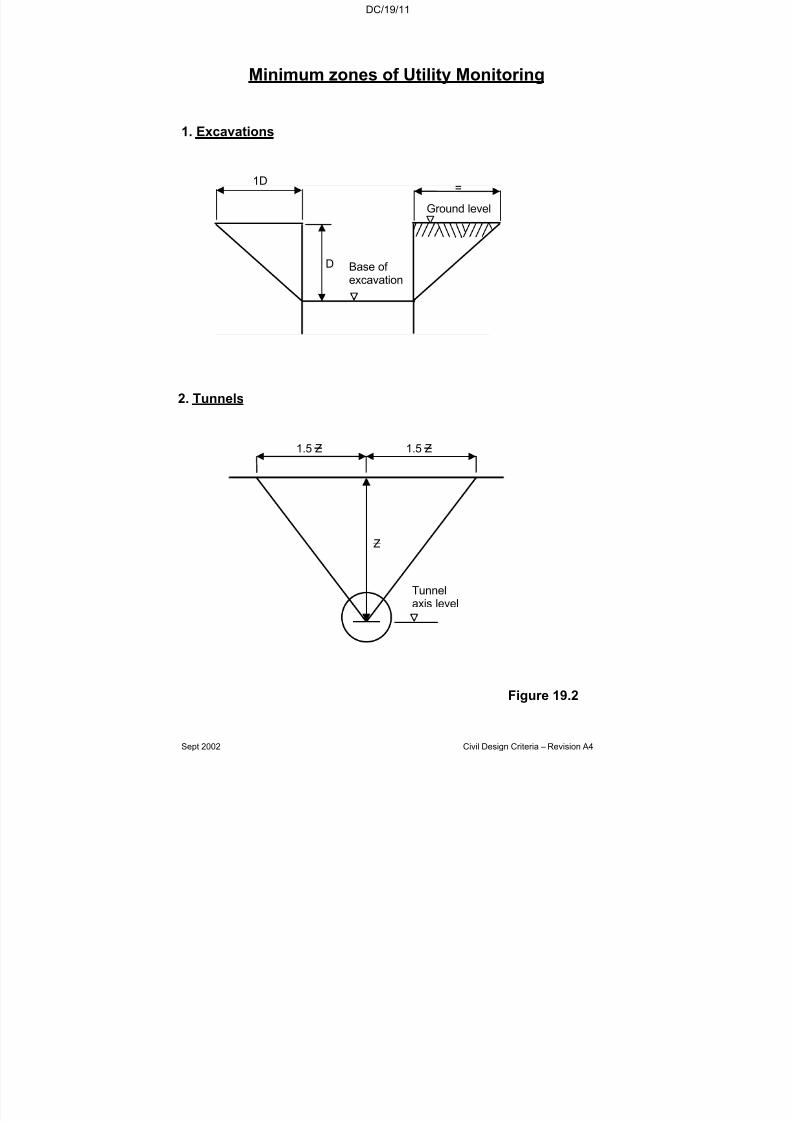
7/18/2019 LTA Civil_standards- Civil Design Criteria
http://slidepdf.com/reader/full/lta-civilstandards-civil-design-criteria 315/345
DC/19/11
Sept 2002 Civil Design Criteria – Revision A4
Minimum zones of Utility Monitoring
1. Excavations
1D=
Ground level
D Base of excavation
Z
Tunnelaxis level
1.5 Z 1.5 Z
2. Tunnels
Figure 19.2
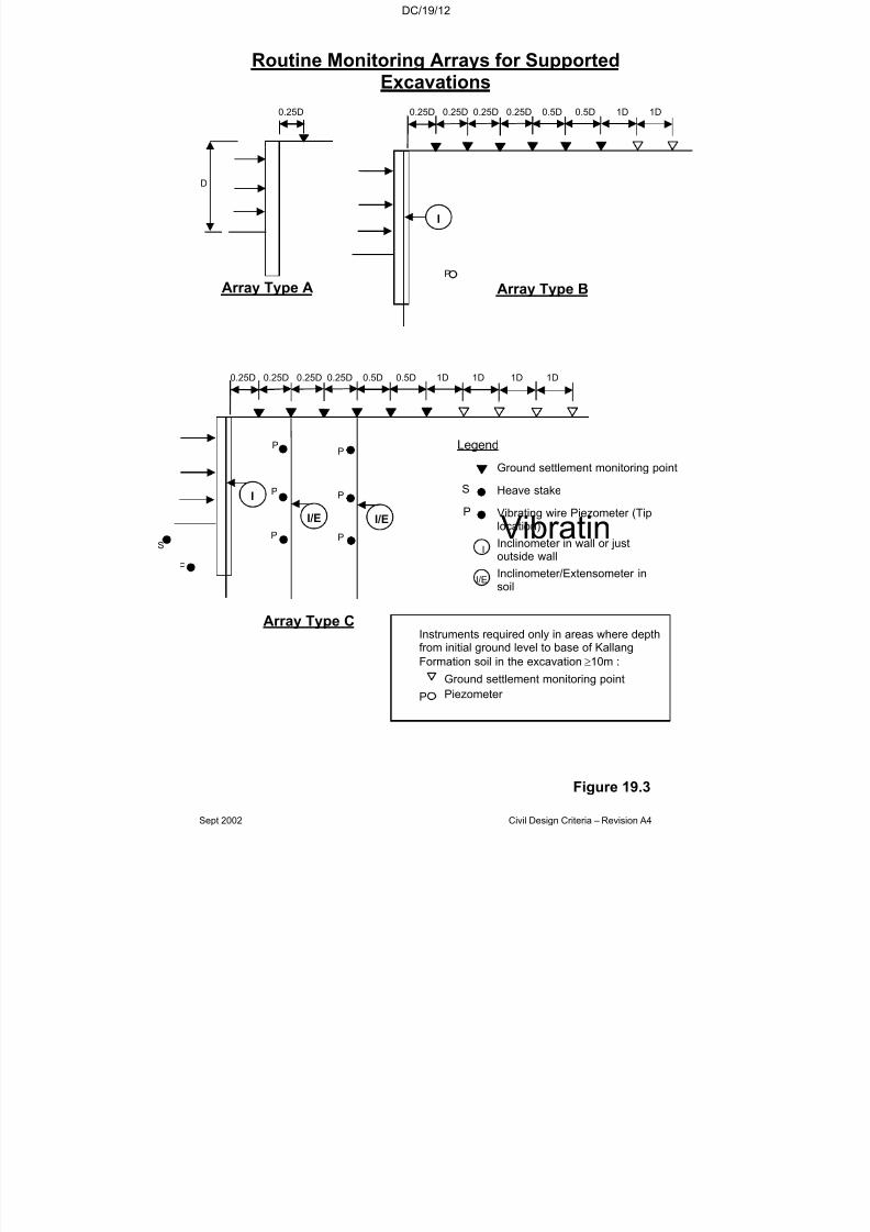
7/18/2019 LTA Civil_standards- Civil Design Criteria
http://slidepdf.com/reader/full/lta-civilstandards-civil-design-criteria 316/345
DC/19/12
Sept 2002 Civil Design Criteria – Revision A4
Routine Monitoring Arrays for SupportedExcavations
0.25D 0.25D 0.25D 0.25D 0.5D 0.5D 1D 1D
I
P
Array Type B
S
0.25D 0.25D 0.25D 0.25D 0.5D 0.5D 1D 1D 1D 1D
IP
I/E
P
P
P
P
P
I/E
Array Type C
D
0.25D
Array Type A
Legend
Figure 19.3
Instruments required only in areas where depthfrom initial ground level to base of Kallang
Formation soil in the excavation ≥10m :
Ground settlement monitoring point
P Piezometer
Heave stake
VibratinP
S
I/E
I
Vibrating wire Piezometer (Tiplocation)
Ground settlement monitoring point
Inclinometer in wall or justoutside wall
Inclinometer/Extensometer insoil
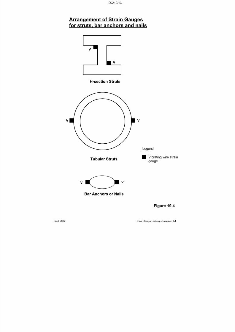
7/18/2019 LTA Civil_standards- Civil Design Criteria
http://slidepdf.com/reader/full/lta-civilstandards-civil-design-criteria 317/345
DC/19/13
Sept 2002 Civil Design Criteria – Revision A4
V
V
H-section Struts
VV
Tubular Struts
Arrangement of Strain Gaugesfor struts, bar anchors and nails
Bar Anchors or Nails
VV
Vibrating wire straingauge
Legend
Figure 19.4
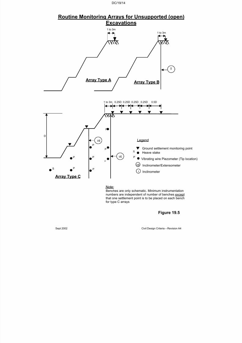
7/18/2019 LTA Civil_standards- Civil Design Criteria
http://slidepdf.com/reader/full/lta-civilstandards-civil-design-criteria 318/345
DC/19/14
Sept 2002 Civil Design Criteria – Revision A4
Routine Monitoring Arrays for Unsupported (open)Excavations
Note:Benches are only schematic. Minimum instrumentationnumbers are independent of number of benches exceptthat one settlement point is to be placed on each benchfor type C arrays
P
D
Array Type C
1 to 3m 0.25D 0.25D 0.25D 0.25D 0.5D
S
P
P P
P
P
P
I/E
I/EVibrating wire Piezometer (Tip location)
Legend
Ground settlement monitoring point
Heave stake
P
S
I/E
I
Array Type A
1 to 3m
Figure 19.5
Array Type B
1 to 3m
I
Inclinometer/Extensometer
Inclinometer
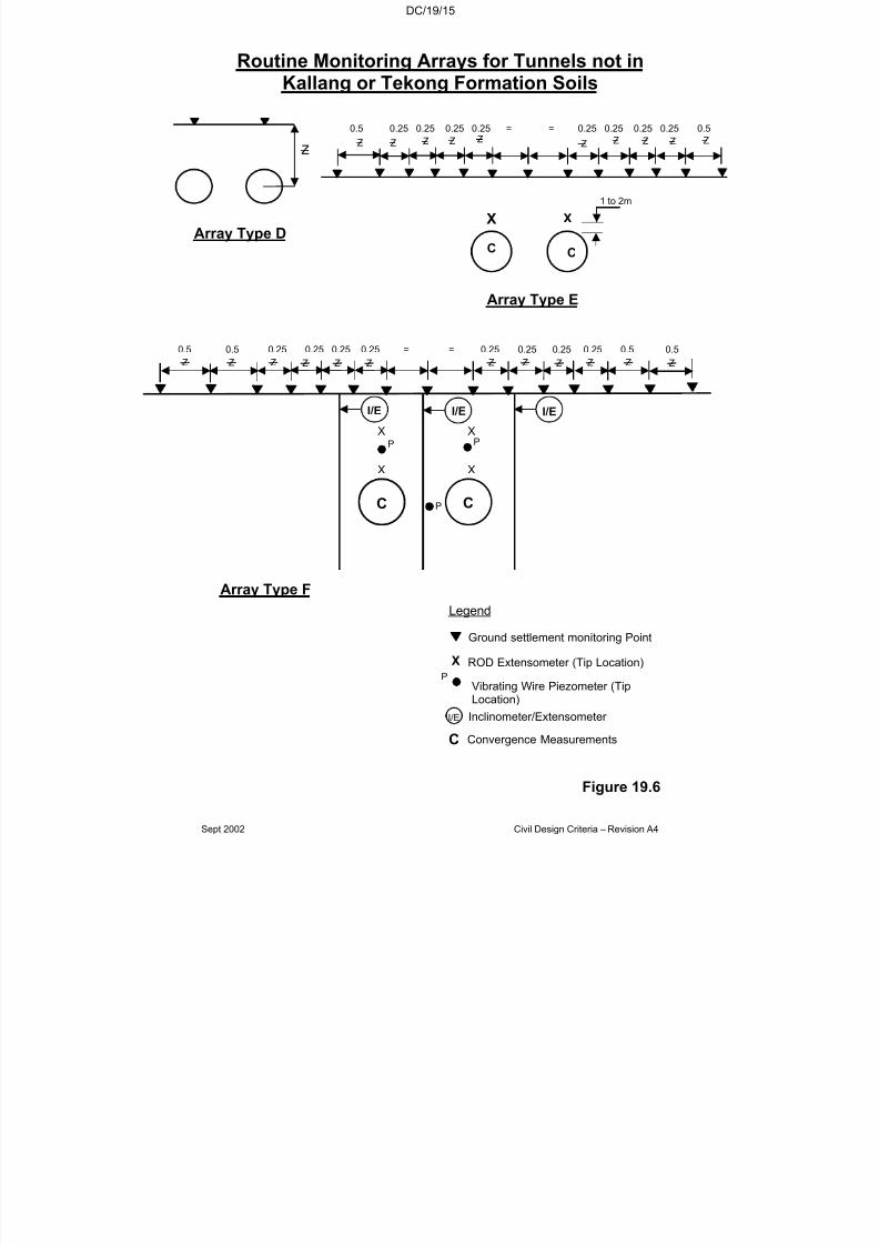
7/18/2019 LTA Civil_standards- Civil Design Criteria
http://slidepdf.com/reader/full/lta-civilstandards-civil-design-criteria 319/345
DC/19/15
Sept 2002 Civil Design Criteria – Revision A4
Routine Monitoring Arrays for Tunnels not inKallang or Tekong Formation Soils
Z
Array Type D
Figure 19.6
Array Type F
C C
0.5 0.5 0.25 0.25 0.25 0.25 = = 0.25 0.25 0.25 0.25 0.5 0.5
I/E I/E I/E
P
P
X XP
X X
Z Z Z Z Z Z Z Z Z Z Z Z
0.5 0.25 0.25 0.25 0.25 = = 0.25 0.25 0.25 0.25 0.5
Array Type E
C C
X X
1 to 2m
Z Z Z Z Z Z Z Z ZZ
ROD Extensometer (Tip Location)
Ground settlement monitoring Point
Legend
Inclinometer/Extensometer
P
X
I/E
C
Vibrating Wire Piezometer (TipLocation)
Convergence Measurements

7/18/2019 LTA Civil_standards- Civil Design Criteria
http://slidepdf.com/reader/full/lta-civilstandards-civil-design-criteria 320/345
DC/19/16
Sept 2002 Civil Design Criteria – Revision A4
Routine Monitoring Arrays for Tunnelswhere any part of the face is in Kallang
or Tekong Formation Soils
Ground settlement monitoring Point
ROD Extensometer (Tip Location)
Legend
Inclinometer/Extensometer
Convergence Measurements
P
X
I/E
C
Array Type F
C C
0.5 0.5 0.25 0.25 0.25 0.25 = = 0.25 0.25 0.25 0.25 0.5 0.5
I/E I/E I/E
P PP
P
P PX
PX
P
P
PX
PX
P
P
P PP
X X
Z Z Z Z Z Z Z Z Z Z Z Z
C C
X X
0.5 0.25 0.25 0.25 0.25 = = 0.25 0.25 0.25 0.25 0.5
1 to 2m
Array Type E
Z Z Z Z Z Z Z Z Z Z
Figure 19.7
Array Type D
Z
Vibrating Wire Piezometer (TipLocation)

7/18/2019 LTA Civil_standards- Civil Design Criteria
http://slidepdf.com/reader/full/lta-civilstandards-civil-design-criteria 321/345
DC/20/1
Sept 2002 Civil Design Criteria – Revision A4
CHAPTER 20
ASSESSMENT OF DAMAGE TO BUILDINGS AND UTILITIES
20.1 GENERAL
The Contractor shall design both temporary and permanent works toensure that ground movements are kept to an absolute minimum. Inaddition, he must recognise the use of proven construction techniquesand good workmanship are essential in restricting ground loss.
Bored tunnels shall be constructed with every effort made to quicklyand adequately support the ground, and to minimise the inflow of water. In squeezing ground, care shall be exercised to ensure thatover-excavation does not take place.
Support systems for excavations shall be selected, where possible, to
avoid exposing ground at the sides of the excavation. Where gaps inthe retaining system are unavoidable, the ground shall be groutedusing at least two rows of injection points.
Construction shall be undertaken with due regard to the settlementsassociated with the particular method chosen. In particular, thefollowing shall be avoided where possible:-
(a) Groundwater lowering by pumping.(b) Groundwater lowering by pervious temporary linings or support
systems.
(c) Use of non-recoverable timber ground supports.
20.2 PREDICTION OF SETTLEMENTS
The Contractor shall predict the settlements due to the Works asdescribed below:
20.2.1 Ground Movements due to Bored Tunnelling
Bored tunnelling work will generally produce a settlement trough which
Peck and O’Reilly and New have related to a Gaussian distributioncurve. These curves are applicable for tunnels where there is no major loss of ground at the face and where there is little or no consolidationsettlement. The Contractor shall use such curves to predict the effect of tunnelling upon adjacent structures.
For a single tunnel, surface settlement, Sv, shall be determined from therelationships:
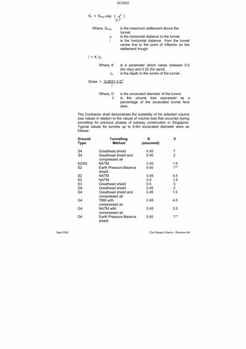
7/18/2019 LTA Civil_standards- Civil Design Criteria
http://slidepdf.com/reader/full/lta-civilstandards-civil-design-criteria 322/345
DC/20/2
Sept 2002 Civil Design Criteria – Revision A4
Sv = Smax exp [ -y2
]2 i2
Where, Smax is the maximum settlement above thetunnel.
y is the horizontal distance to the tunnel.i is the horizontal distance from the tunnel
centre line to the point of inflexion on thesettlement trough.
i = K zo
Where, K is a parameter which varies between 0.5(for clay) and 0.25 (for sand).
zo is the depth to the centre of the tunnel.
Smax = 0.0031 V D2
i
Where, D is the excavated diameter of the tunnel.V is the volume loss expressed as a
percentage of the excavated tunnel facearea.
The Contractor shall demonstrate the suitability of his selected volumeloss values in relation to the values of volume loss that occurred duringtunnelling for previous phases of subway construction in Singapore.Typical values for tunnels up to 6.6m excavated diameter were asfollows:
Ground Tunnelling K VType Method (assumed)
S4 Greathead shield 0.45 7S4 Greathead shield and 0.45 2
compressed air S2/S4 NATM 0.45 1.5S2 Earth Pressure Balance 0.45 1**
shield.S2 NATM 0.45 0.5
S3 NATM 0.5 1.5S3 Greathead shield 0.5 5G4 Greathead shield 0.45 2G4 Greathead shield and 0.45 1.5
compressed air G4 TBM with 0.45 4.5
compressed air G4 NATM with 0.45 3.5
compressed air G4 Earth Pressure Balance 0.45 1**
shield.
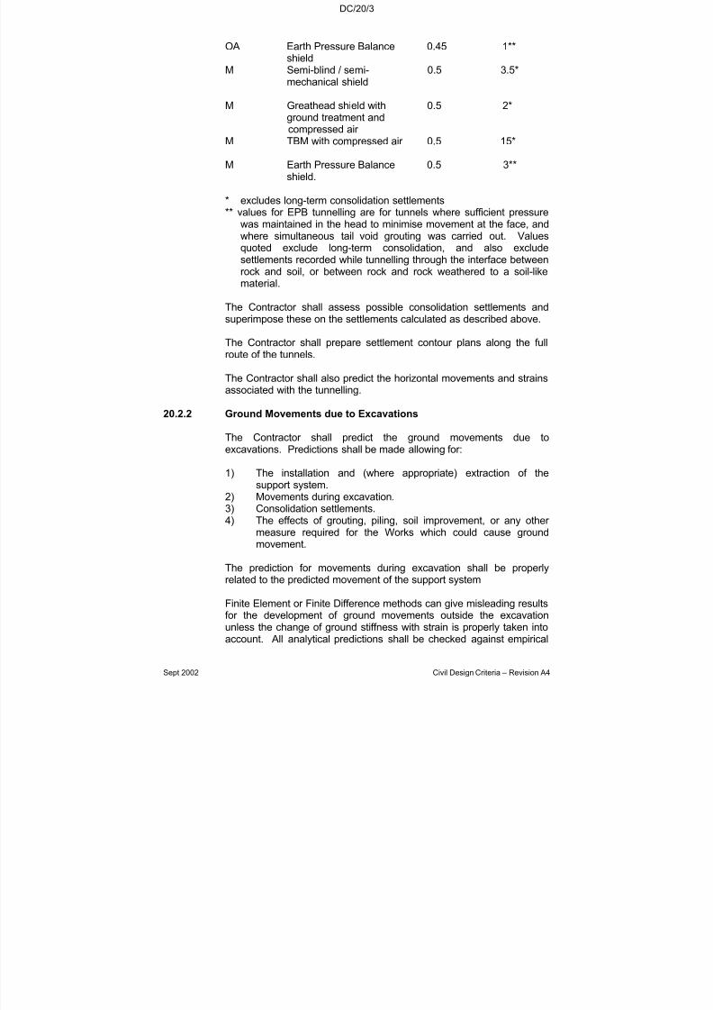
7/18/2019 LTA Civil_standards- Civil Design Criteria
http://slidepdf.com/reader/full/lta-civilstandards-civil-design-criteria 323/345
DC/20/3
Sept 2002 Civil Design Criteria – Revision A4
OA Earth Pressure Balance 0.45 1**shield
M Semi-blind / semi- 0.5 3.5*mechanical shield
M Greathead shield with 0.5 2*ground treatment and
compressed air M TBM with compressed air 0.5 15*
M Earth Pressure Balance 0.5 3**shield.
* excludes long-term consolidation settlements** values for EPB tunnelling are for tunnels where sufficient pressure
was maintained in the head to minimise movement at the face, andwhere simultaneous tail void grouting was carried out. Valuesquoted exclude long-term consolidation, and also exclude
settlements recorded while tunnelling through the interface betweenrock and soil, or between rock and rock weathered to a soil-likematerial.
The Contractor shall assess possible consolidation settlements andsuperimpose these on the settlements calculated as described above.
The Contractor shall prepare settlement contour plans along the fullroute of the tunnels.
The Contractor shall also predict the horizontal movements and strains
associated with the tunnelling.
20.2.2 Ground Movements due to Excavations
The Contractor shall predict the ground movements due toexcavations. Predictions shall be made allowing for:
1) The installation and (where appropriate) extraction of thesupport system.
2) Movements during excavation.3) Consolidation settlements.
4) The effects of grouting, piling, soil improvement, or any other measure required for the Works which could cause groundmovement.
The prediction for movements during excavation shall be properlyrelated to the predicted movement of the support system
Finite Element or Finite Difference methods can give misleading resultsfor the development of ground movements outside the excavationunless the change of ground stiffness with strain is properly taken intoaccount. All analytical predictions shall be checked against empirical
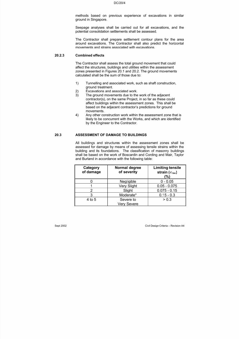
7/18/2019 LTA Civil_standards- Civil Design Criteria
http://slidepdf.com/reader/full/lta-civilstandards-civil-design-criteria 324/345
DC/20/4
Sept 2002 Civil Design Criteria – Revision A4
methods based on previous experience of excavations in similar ground in Singapore.
Seepage analyses shall be carried out for all excavations, and thepotential consolidation settlements shall be assessed.
The Contractor shall prepare settlement contour plans for the area
around excavations. The Contractor shall also predict the horizontalmovements and strains associated with excavations.
20.2.3 Combined effects
The Contractor shall assess the total ground movement that couldaffect the structures, buildings and utilities within the assessmentzones presented in Figures 20.1 and 20.2. The ground movementscalculated shall be the sum of those due to:
1) Tunnelling and associated work, such as shaft construction,
ground treatment.2) Excavations and associated work.3) The ground movements due to the work of the adjacent
contractor(s), on the same Project, in so far as these couldaffect buildings within the assessment zones. This shall bebased on the adjacent contractor’s predictions for groundmovements.
4) Any other construction work within the assessment zone that islikely to be concurrent with the Works, and which are identifiedby the Engineer to the Contractor.
20.3 ASSESSMENT OF DAMAGE TO BUILDINGS
All buildings and structures within the assessment zones shall beassessed for damage by means of assessing tensile strains within thebuilding and its foundations. The classification of masonry buildingsshall be based on the work of Boscardin and Cording and Mair, Taylor and Burland in accordance with the following table:
Categoryof damage
Normal degreeof severity
Limiting tensile
strain (∈lim)
(%)0 Negligible 0 - 0.05
1 Very Slight 0.05 - 0.075
2 Slight 0.075 - 0.15
3 Moderate* 0.15 - 0.3
4 to 5 Severe toVery Severe
> 0.3

7/18/2019 LTA Civil_standards- Civil Design Criteria
http://slidepdf.com/reader/full/lta-civilstandards-civil-design-criteria 325/345
DC/20/5
Sept 2002 Civil Design Criteria – Revision A4
The description of the damage associated by the degrees of severity isgiven in Appendix 1. The Contractor shall determine a similar andcompatible association for framed and other structures.
Due account shall be taken of any stiffness in the buildings to resistground deformations.
Generally, the staged assessment approach outlined in Mair, Taylor and Burland shall be used. However, it is quite common for buildingsin Singapore to be constructed or renovated such that they have mixedfoundations. These buildings can be particularly sensitive tosettlement. For any building or structure that is identified as being onmixed foundations, the contractor shall carry out a detailed evaluation,taking into account the nature of the building/structure and thefoundations.
The Contractor shall summarise his assessment for every buildingwithin the assessment zone, using the layout shown in Figure 20.3.
20.4 ASSESSMENT OF DAMAGE TO UTILITIES
The Contractor shall carry out a damage assessment for every utilitywithin the Utility Assessment Zone. The contractor shall establish, withthe relevant utility agency, allowable values for settlement,deformation, joint rotation, joint slip, or such other criteria as are agreedwith the utility agency. The allowable values shall ensure that the utilitycan be kept fully functional throughout the Works, and that it will not besuffer significant loss of durability. Where necessary, the Contractor
shall carry out trial pits to confirm the nature of the utility and jointspacing.
Particular attention shall be given to the junction of pipes and spurs off the pipe, as outlined by Attewell, Yates and Selby. For cast iron pipesthe methodology of Bracegirdle, Mair, Nyren and Taylor shall befollowed.
The Contractor shall summarise his assessment for every utility withinthe assessment zone. The summary shall include details of the type of utility, nature, joint type and spacing, and the allowable and predicted
values for settlement, deformation, joint rotation, joint slip, or suchother criteria as are agreed with the utility agency. As far as possiblethis information shall be tabulated.
20.5 PROTECTIVE WORKS
The Contractor shall design and install protective works to all buildingswhere the predicted degree of severity of settlement damage is“moderate” or above, with the aim to restrict damage to the “slight”category or below. Where a building has historical or other
7/18/2019 LTA Civil_standards- Civil Design Criteria
http://slidepdf.com/reader/full/lta-civilstandards-civil-design-criteria 326/345
DC/20/6
Sept 2002 Civil Design Criteria – Revision A4
significance, as stated in the Particular Specification, protective worksshall be designed and installed if the predicted damage is in the “slight”category or above,with the aim of restricting damage to the “very slight”category. The above requirement shall not apply to buildings that arederelict or awaiting demolition.
Protective works shall be in the form of underpinning, ground
improvements, compaction or compensation grouting, jacking or building strengthening or some combination of these or such other means as the Contractor shall select to the acceptance of the Engineer.Care shall be taken to ensure that the selected method of protectiondoes not do more harm to the building than the original settlements.
Where any of the predicted values for a utility exceeds the allowablevalue, the Contractor shall design and implement protective measures.Protective works shall be in the form of excavation and support,underpinning, ground improvements, compaction or compensationgrouting, jacking or such other means as the Contractor shall select to
the acceptance of the Engineer.
If a building, structure or utility is likely to be affected by groundmovements due to the work of two or more contractors, andunacceptable damage is predicted, then the Contractor shallcoordinate with the other contractor(s) and agree appropriate protectivemeasures.
References
Peck RB. Deep excavation and tunnelling in soft ground. State of the Art Report. 7thInternational Conference on Soil Mechanics and Foundation Engineering, MexicoCity 1969.
Terzaghi K. Rock tunnelling with steel supports, Section 1, Commercial Shearingand Stamping Co. 1946.
Proctor & White. Rock tunnelling with steel supports. Commercial Shearing andStamping Co. 1946.
O’Reilly MP and New BM. Settlements above tunnels in the United Kingdom - their
magnitude and prediction. Tunnelling ‘82, London. 1992.
New BM and O’Reilly.Tunnelling induced ground movements: predicting MP.their magnitude and effect. 4th Int. Conf. on Ground Movements and Structures. Cardiff.1991.
Boscardin MD and Cording EG. Building response to excavation-induced andsettlement. Journal Geotechnical Engineering, ASCE, vol 115. 1989.

7/18/2019 LTA Civil_standards- Civil Design Criteria
http://slidepdf.com/reader/full/lta-civilstandards-civil-design-criteria 327/345
DC/20/7
Sept 2002 Civil Design Criteria – Revision A4
Mair RJ, Taylor RN and Burland JB. Prediction of ground movements andassessment of risk of building damage due to bored tunnelling. Int. Symp. onGeotechnical Aspects of Underground Construction in Soft Ground, London, 1996.
Burland JB, Broms B and De Mello VFB. Behaviour of Foundations and Structures.State of the Art Report, Session 2, Proc. 9th Int. Conf. of Soil Mechanics andFoundation Engineering, Tokyo 1977.
Attewell, Yeates and Selby. Soil movements induced by tunnelling and their effectson pipelines and structures. Blackie and Sons, London. 1996.
Bracegirdle, A. Mair, R.J., Nyren, R.J. and Taylor, R.N. A simple methodology for evaluating the potential damage to buried cast iron pipes from ground movementarising from tunnelling. . Int. Symp. on Geotechnical Aspects of UndergroundConstruction in Soft Ground, London, 1996.
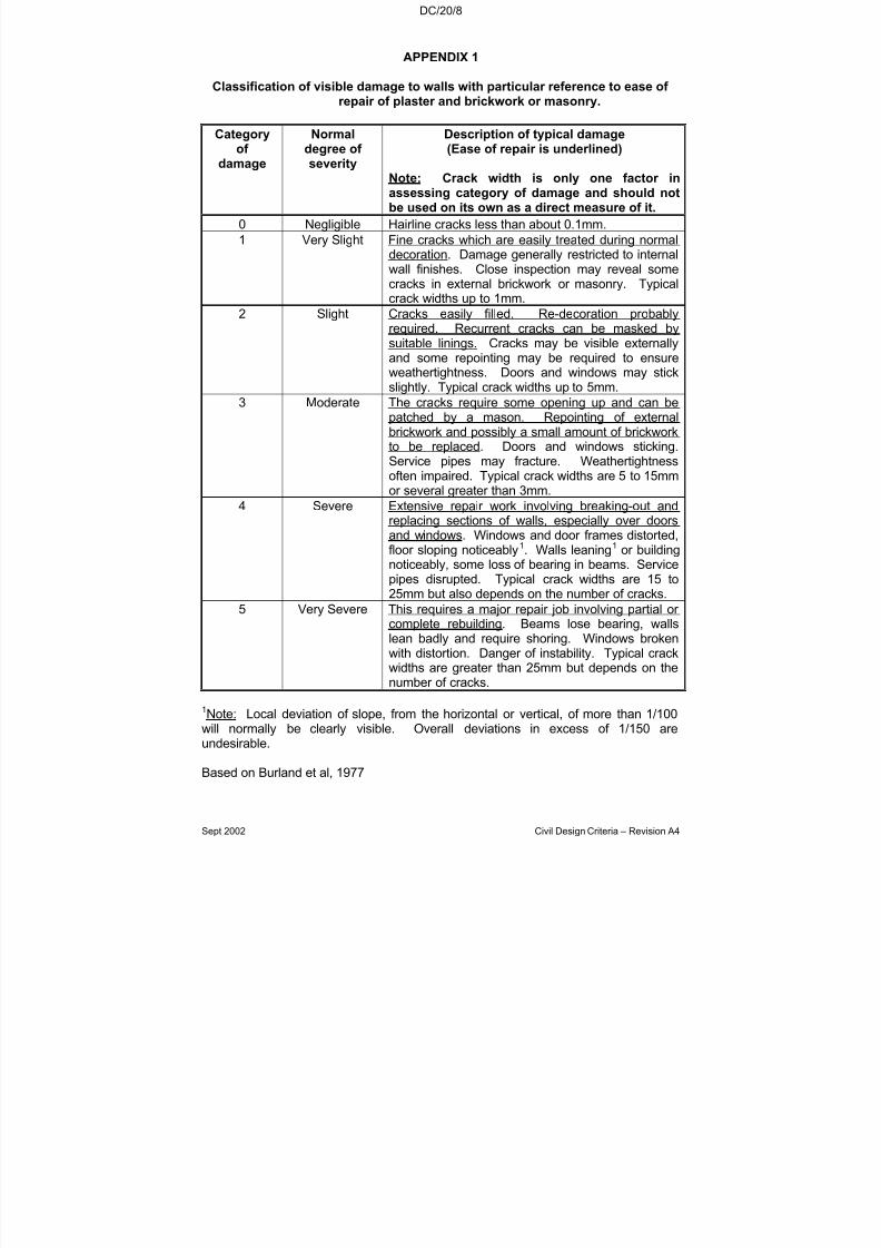
7/18/2019 LTA Civil_standards- Civil Design Criteria
http://slidepdf.com/reader/full/lta-civilstandards-civil-design-criteria 328/345
DC/20/8
Sept 2002 Civil Design Criteria – Revision A4
APPENDIX 1
Classification of visible damage to walls with particular reference to ease of repair of plaster and brickwork or masonry.
Categoryof
damage
Normaldegree of
severity
Description of typical damage(Ease of repair is underlined)
Note: Crack width is only one factor inassessing category of damage and should notbe used on its own as a direct measure of it.
0 Negligible Hairline cracks less than about 0.1mm.
1 Very Slight Fine cracks which are easily treated during normaldecoration. Damage generally restricted to internalwall finishes. Close inspection may reveal somecracks in external brickwork or masonry. Typicalcrack widths up to 1mm.
2 Slight Cracks easily filled. Re-decoration probably
required. Recurrent cracks can be masked bysuitable linings. Cracks may be visible externallyand some repointing may be required to ensureweathertightness. Doors and windows may stickslightly. Typical crack widths up to 5mm.
3 Moderate The cracks require some opening up and can bepatched by a mason. Repointing of externalbrickwork and possibly a small amount of brickworkto be replaced. Doors and windows sticking.Service pipes may fracture. Weathertightnessoften impaired. Typical crack widths are 5 to 15mm
or several greater than 3mm.4 Severe Extensive repair work involving breaking-out and
replacing sections of walls, especially over doorsand windows. Windows and door frames distorted,floor sloping noticeably1. Walls leaning1 or buildingnoticeably, some loss of bearing in beams. Servicepipes disrupted. Typical crack widths are 15 to25mm but also depends on the number of cracks.
5 Very Severe This requires a major repair job involving partial or complete rebuilding. Beams lose bearing, wallslean badly and require shoring. Windows broken
with distortion. Danger of instability. Typical crackwidths are greater than 25mm but depends on thenumber of cracks.
1Note: Local deviation of slope, from the horizontal or vertical, of more than 1/100will normally be clearly visible. Overall deviations in excess of 1/150 areundesirable.
Based on Burland et al, 1977
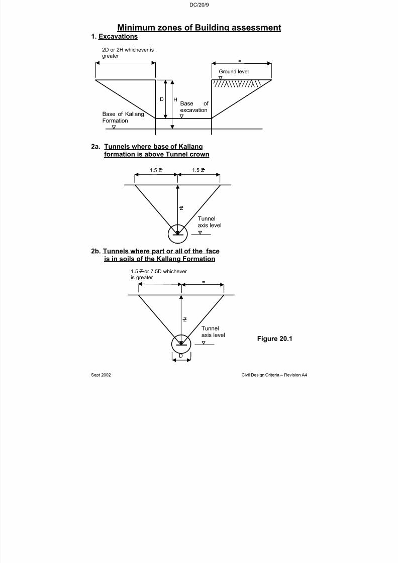
7/18/2019 LTA Civil_standards- Civil Design Criteria
http://slidepdf.com/reader/full/lta-civilstandards-civil-design-criteria 329/345
DC/20/9
Sept 2002 Civil Design Criteria – Revision A4
Minimum zones of Building assessment1. Excavations
2a. Tunnels where base of Kallangformation is above Tunnel crown
2b. Tunnels where part or all of the faceis in soils of the Kallang Formation
Figure 20.1
2D or 2H whichever isgreater
=
Ground level
Base of KallangFormation
D HBase of excavation
1.5 Z or 7.5D whichever is greater
=
D
Z
Tunnelaxis level
1.5 Z 1.5 Z
Tunnelaxis level
Z

7/18/2019 LTA Civil_standards- Civil Design Criteria
http://slidepdf.com/reader/full/lta-civilstandards-civil-design-criteria 330/345

7/18/2019 LTA Civil_standards- Civil Design Criteria
http://slidepdf.com/reader/full/lta-civilstandards-civil-design-criteria 331/345
7/18/2019 LTA Civil_standards- Civil Design Criteria
http://slidepdf.com/reader/full/lta-civilstandards-civil-design-criteria 332/345
DC/21/1
Sept 2002 Civil Design Criteria – Revision A4
CHAPTER 21
LIGHTING SYSTEM
21.1 PUBLIC STREET LIGHTING
21.1.1 General
The design of lighting shall be based on the latest edition of the followingpublications:
(a) BS 5489 (British Standard)
(b) CIE 115-1995(Technical Report of Commission Internationale deL’Eclairage)
Road surface shall be taken as Class R3 road (Asphalt CIE R3). The
design shall also comply with the applicable Codes, Regulations,Standards and relevant Authorities.
21.1.2 Luminaires Requirements
The luminaires shall be semi-cutoff or cutoff type complete with integralcontrol gears suitable for use with high pressure sodium vapour lamps ona supply voltage of 230 volts + 6%, 50 Hz. It shall have a clear acrylicbowl with integral control for use with 70W, 150W, 250W and 400Wtubular high pressure sodium vapour (SON/T) lamps. The mountingheights can be ranged from 6 to 14 metres depending on the actual
requirements. Each lantern shall be adjustable for at least full cut-off andsemi cut-off light distribution as per CIE (International Commission onIllumination) definitions. All components such as lampholder, ballast,igniter and capacitor shall comply with and be tested to the requirementsof the relevant Singapore or equivalent standards.
Attachment of a lantern to its side entry bracket arm shall be by means of clamps and designed to accommodate bracket arm tube diameters of 40to 80 mm. The length of penetration of a side entry bracket arm shall be atleast 100mm. The mounting arrangement and wind resistant area of aluminaire shall be such as to withstand a wind-speed of 100 km per hour
with a factor of safety of 5.
All fixings which carry the weight of the luminaire and the internalaccessories shall be provided with suitable locking devices to prevent thedislodgement of any part of the luminaire by vibration either in service or during maintenance.

7/18/2019 LTA Civil_standards- Civil Design Criteria
http://slidepdf.com/reader/full/lta-civilstandards-civil-design-criteria 333/345
DC/21/2
Sept 2002 Civil Design Criteria – Revision A4
21.1.3 Works in Conjunction with Lighting
Mounting details including all data, calculations, imposed loads and forcesand dimensional drawings for the foundations required (piling if necessary) for the poles shall be endorsed by a registered ProfessionalEngineer. The soil bearing capacity at the site shall be ascertained so thatthe foundations can be correctly designed. Base plates, holding-down
bolts etc. shall be provided for the installation of street lighting. Heavy-duty UPVC pipes Class B with pull-wire shall be provided for theunderground cables.
All outgoing undergound cables from street lighting control box shall besupplied and laid by LTA. Co-ordination and interfacing of incomingsupply cabling work to street lighting control box with PowerGrid Ltd shallbe carried out by the developer.
21.2 VEHICULAR UNDERPASS LIGHTING
21.2.1 General
The vehicular underpass lighting system shall consist of continuous line of luminaires with fluorescent lamps, running along the carriagewaysmounted on the tunnel ceiling. This arrangement will provide acontinuous line of light for visual guidance for daytime and nightimeoperation.
Road surface shall be taken as Class R3 road (Asphalt CIE R3).Uniformity in the underpass shall not be less than 0.8. Indirect
contribution from wall and roof of the tunnel shall be neglected and shallnot be considered in the design. The uniformity is defined as the ratio of minimum illuminance to the designed avergae illuminance.
The design of lighting shall be based on the latest edition of the followingpublications:
(a) BS 5489 (British Standard)
(b) CIE 115-1995 (Technical Report of Commission Internationale deL’Eclairage)
The design shall also comply with the applicable Codes, Regulations,Standards and relevant Authorities
Control circuit shall be included with the lighting sub-circuits for night timedimming of the fluorescent luminaires shall be provided. The dimmingmodules shall be provided with electronic ballasts in the luminaire.Dimming of the fluorescent luminaires shall be continuous.
Under Night Stage lighting switching, the total luminaires output shall bereduced to 50% of the daytime value.

7/18/2019 LTA Civil_standards- Civil Design Criteria
http://slidepdf.com/reader/full/lta-civilstandards-civil-design-criteria 334/345
DC/21/3
Sept 2002 Civil Design Criteria – Revision A4
A ripple controller shall be installed to switch the lights at night. The ripplecontrol receiver shall collect and transmit the signals to activate thelighting contactor which will in turn enable the switching facilities.
21.2.2 Emergency Lighting
In the event of power failure, the vehicular lighting system shall bemaintained for 1 hour by means of individual emergency battery packs.The battery packs shall be designed to comply with the latest edition of CP 19.
21.2.3 Luminaires Requirements
All luminaires complete with all accessories shall be of a type speciallydesigned for use in vehicular underpass. Luminaires shall comply with BS4533 and IEC Degrees of Protection IP 65 including requirements in
jetproofing, thermal testing and dustproofing. Housing shall be painted by
an electrostatic process. The gear trays and other fixing inside theluminaire shall be of non-corrodible material. Underpass lighting fittingsshall be fixed by means of accepted non-ferrous metal fasteners.
All steel parts and surfaces shall be hot dipped galvanised to withstandcorrosive atmosphere according to BS 729..
All underpass lighting sub-circuits shall consist of fire resistant, low smoke,halogen free armoured cables. Engraved cable ferrules shall be fixed tothe end of each cable at the distribution board outgoing terminal blocks toidentify each subcircuits shall be provided.
For luminaires fed from normal mains supply, a metal clad corrosion proof junction box shall be provided at the first lighting fitting connected to thesubcircuit for tee-off cable connection. All cable entries to the junctionboxes shall be terminated with weatherproof type cable glands, sealedagainst water ingress by the provision of non-setting sealing compound andwith cable shroud after cable connection. Cables shall be supported incable trays or cable ducts throughout and by cable ladder wherenecessary.
Brass earthing bushes shall be provided in each junction box for bonding of
copper sheaths or armour. Copper earthing conductor shall be used toensure earth continuity.
Design calculations to justify on the adequacy of the support system withdetails of all equipment and cables total weight in worst case shall beendorsed by a professionally-qualified, registered engineer.

7/18/2019 LTA Civil_standards- Civil Design Criteria
http://slidepdf.com/reader/full/lta-civilstandards-civil-design-criteria 335/345
DC/21/4
Sept 2002 Civil Design Criteria – Revision A4
21.3 TUNNEL LIGHTING
21.3.1 General
The design of lighting shall be based on the latest edition of the followingpublications:
(a) Road lighting Part 7 Code of Practice for the lighting of tunnelsand underpasses – BS 5489 : Part 7 (British Standard)
(b) Guide for the lighting of road tunnels and underpasses – CIE 115-1995 (Technical Report of Commission Internationale deL’Eclairage)
(c) Permanent International Associations of Roads Congresses –Report to 18th, 19th and 20th Congresses on Road Tunnels –1987, 1991 and 1995
21.3.2 Design Parameters
Acceptable daytime design practice requires that the tunnel lightingsystem be divided into several zones to allow a motorist’s eyes to adaptprogressively to the passage from bright daylight to the darker interior.These zones are defined as follows:
(a) Threshold Zone – The first section inward from the portal, whichmust have the highest luminance to avoid an abrupt decreasefrom exterior daylight.
(b) Transition Zone – A gradual or stepped reduction of luminancefrom the higher level in the threshold zone to the lower level in theinterior zone.
(c) Exit Zone – The last section of the tunnel which has a higher luminance than the interior zone to adapt the motorist’s eyes backto exterior daytime.
The design of the lighting levels in each zone shall follow acceptedpractice and shall be based on the daytime luminance of the approachroad before a tunnel portal, referred to as the access zone and the design
speed. In general, the recommendations of the latest edition of BS 5489Part 7 shall be used for detail design work. The following parameters areto be considered in the design:
(a) Design speed : The design speed used in the lightingcalculations shall be subject to theapproval of the Authority.
(b) Stopping sightdistance
: The stopping sight distance shall bebased on the recommendations of CIE115:1995.
7/18/2019 LTA Civil_standards- Civil Design Criteria
http://slidepdf.com/reader/full/lta-civilstandards-civil-design-criteria 336/345
DC/21/5
Sept 2002 Civil Design Criteria – Revision A4
(c) The accesszone luminance(L20)
: The access zone luminance shall bebased on recommendations in Table 5.1CIE 115:1995 and subject to siteinvestigations.
(d) Ratio of
threshold zoneluminance (Lth)to access zoneluminance (L20)
: Table 2 of BS 5489 : Part 7
(e) Luminance of threshold zoneduring daylight(Lth)
: The luminance of threshold zone duringdaylight shall be based on therecommendations of CIE 115:1995.
(f) Length of
threshold zone
: BS 5489 : Part 7
(g) Luminancedecreasebetweensuccessivezones
: Not greater than 3:1(As required by Clause 8(f) in BS 5489 :Part 7)
(h) Length andluminance of transition zones
: The luminance reduction curve shownon Figure 3 in BS 5489 : Part 7 shall beused in detail design.
(i) Average interior zone luminance(Lin):
DaytimeNighttime
::
Not less than 6 cd/m2
Half of daytime level
(j) Uniformity:
Overalluniformity of
traffic lanes andshoulder (UO)Longitudinaluniformity alongtraffic lanes (UL)
:
:
0.4
0.5
(k) Exit zoneluminanceduring daylight
: BS 5489 : Part 7

7/18/2019 LTA Civil_standards- Civil Design Criteria
http://slidepdf.com/reader/full/lta-civilstandards-civil-design-criteria 337/345
DC/21/6
Sept 2002 Civil Design Criteria – Revision A4
(l) Switchingcontrol
: Luminance meters shall be provided atentrance portals to adjust the entrancezone lighting level in accordance withthe actual access zone luminance
The design shall consider the optimisation of lamplife and maintenance.
21.3.3 Glare Control
Glare control as Threshold Increment (TI) set out within BS 5489 Part 1and 2 shall be considered within the design and selection of luminaire andtype of light source. The TI within the tunnel shall not exceed 15 %.
21.3.4 Emergency Lighting
In the event of power failure, the tunnel lighting system shall bemaintained for 1 hour by means of individual emergency battery packs.The battery packs shall be designed to comply with the latest edition of
CP 19. An adequately sized standby generator shall also be provided tosupport the tunnel lighting system in the event of a power failure.

7/18/2019 LTA Civil_standards- Civil Design Criteria
http://slidepdf.com/reader/full/lta-civilstandards-civil-design-criteria 338/345
DC/AP/1
Sept 2002 Civil Design Criteria – Revision A4
APPENDIX A
DESIGN CHECK LIST
The Contractor shall ensure that his design as shown on all Drawings and Contract
documents is complete.
The check list as shown on the following pages are compiled from obvious omissionsin previous MRT phases. The list is not meant to be exhaustive and it is theContractor’s duty to ensure that he has a complete design for construction.

7/18/2019 LTA Civil_standards- Civil Design Criteria
http://slidepdf.com/reader/full/lta-civilstandards-civil-design-criteria 339/345
DC/AP/2
Sept 2002 Civil Design Criteria – Revision A4
A STATIONS - GENERAL
1. Access catladder - Provide approved standardised catladders tounderplatform voids, vent shafts, hatches, cable towers, E&M equipment, etc.
2. Platform endstairs - Provide safe platform endstairs for use duringemergency situation, i.e adequate width, preferably 900 mm, but not lessthan 600 mm, and bottom riser not more than 170 mm.
3. Floor hatch cover - All floor hatch cover should be flush with the floor andprotected against damage by heavy E & M equipment movement.
4. Maintenance Platform - Provide adequate platform with railings/catladdersfor maintenance access to E&M equipment, louvres, valves, water tanks,switches, etc at high level.
5. Platform end walkways - E&M equipment mounted on the walls should notcause the platform end walkways to have inadequate width for emergencyegress.
6. Escalators - The railing balustrade design should tie in with the escalator toprevent children from falling.
Slope surface between two escalators need some means to deter people fromsliding down.
Provide deterrent triangles at beams/slabs that are near the escalators edge.
The gap between the escalator handrail and adjacent handrail should be atleast 80 mm apart.
Provide safety switch at roller shutter gate entrance so that the escalators willonly move when the shutter gate is fully opened.
7. Channel Gratings - provide gratings over channels/drains where access isneeded.
8. Taps and Drain Pipes - All discharge points to water taps and aircon drain
pipes shall be directly over or near floor traps.
No water tap is allowed to be installed inside the distribution board room or inother rooms where there are electrical accessories. It should be located atleast 2 m away.
9. PUB valve chambers - All PUB incoming valve chambers are to be designedwith drainage provision and meter reading facility.

7/18/2019 LTA Civil_standards- Civil Design Criteria
http://slidepdf.com/reader/full/lta-civilstandards-civil-design-criteria 340/345
7/18/2019 LTA Civil_standards- Civil Design Criteria
http://slidepdf.com/reader/full/lta-civilstandards-civil-design-criteria 341/345
DC/AP/4
Sept 2002 Civil Design Criteria – Revision A4
B UNDERGROUND STATIONS
1. Buffet Area Railings - Provide handrailings on buffet area outside the tractionsubstation to 5 m from the station screen door end return.
2. Halon Cylinder Storage - Provide proper fire-rated enclosure for haloncylinder storage.
3. Doors with direct access to track - Provide safety bar and warning sign for doors that provide direct access to trackside from station rooms.
4. CD airfilters - CD station airfilters in rooms should not obstruct the opening of the door access.
5. Cooling tower rooms - Design for adequate drainage facilities to preventflooding of rooms due to backflow of water from cooling tower.
7/18/2019 LTA Civil_standards- Civil Design Criteria
http://slidepdf.com/reader/full/lta-civilstandards-civil-design-criteria 342/345
7/18/2019 LTA Civil_standards- Civil Design Criteria
http://slidepdf.com/reader/full/lta-civilstandards-civil-design-criteria 343/345
7/18/2019 LTA Civil_standards- Civil Design Criteria
http://slidepdf.com/reader/full/lta-civilstandards-civil-design-criteria 344/345
DC/AP/7
Sept 2002 Civil Design Criteria – Revision A4
E TUNNELS
1. Sump Pump Control Panel - Provide proper access to tunnel sump pumpcontrol panels.
2. Blast Door roller housing - Provide ramps to blast door roller housing whichis above the track level.
3. Tunnel Booster Fans - provide collapse frame and maintenance accessplatform to the tunnel booster fan units.
4. Floating Slab Track - gap between floating slab track and tunnel wall to bebackfilled.
5. Trackside Drain - trackside drain near platform steps to be covered withgratings.
7/18/2019 LTA Civil_standards- Civil Design Criteria
http://slidepdf.com/reader/full/lta-civilstandards-civil-design-criteria 345/345
DC/AP/8
F VIADUCTS
1. Low viaduct parapet on non-walkway side - Provide additional railings on thelow parapet wall where there is no third rail to act as deterrent for staff safety.
2. Viaduct near station end stairs - 3 m of handrailing to be provided on parapetleading to emergency access from track to end stairs.
3. Bearings - Are they all accessible for future maintenance and replacement?
Check at non-standard location such as cross over beams, at station etc.
4. Drainage system for viaduct - Is the system designed for movements of viaduct beams?
5. Walkways - Should have no dead ends.
6. Railings - To be provided near station at places where detrained passenger is likely to make use of for escape.
7. Vandals - Are there adequate barriers at at-grade section to prevent vandalsfrom getting onto viaducts?


