Hindawi Publishing CorporationEURASIP Journal on Wireless Communications and NetworkingVolume 2009, Article ID 989062, 13 pagesdoi:10.1155/2009/989062
Research ArticleLTE Adaptation for Mobile Broadband Satellite Networks
Francesco Bastia, Cecilia Bersani, Enzo Alberto Candreva, Stefano Cioni,
Giovanni Emanuele Corazza, Massimo Neri, Claudio Palestini, Marco Papaleo,
Stefano Rosati, and Alessandro Vanelli-Coralli
ARCES, University of Bologna, Via V. To ff ano, 2/2, 40125 Bologna, Italy
Correspondence should be addressed to Stefano Cioni, [email protected]
Received 31 January 2009; Revised 29 May 2009; Accepted 30 July 2009
Recommended by Constantinos B. Papadias
One of the key factors for the successful deployment of mobile satellite systems in 4G networks is the maximization of thetechnology commonalities with the terrestrial systems. An eff ective way of achieving this objective consists in considering theterrestrial radio interface as the baseline for the satellite radio interface. Since the 3GPP Long Term Evolution (LTE) standardwill be one of the main players in the 4G scenario, along with other emerging technologies, such as mobile WiMAX; this paperanalyzes the possible applicability of the 3GPP LTE interface to satellite transmission, presenting several enabling techniques forthis adaptation. In particular, we propose the introduction of an inter-TTI interleaving technique that exploits the existing H-ARQfacilities provided by the LTE physical layer, the use of PAPR reduction techniques to increase the resilience of the OFDM waveformto non linear distortion, and the design of the sequences for Random Access, taking into account the requirements deriving fromthe large round trip times. The outcomes of this analysis show that, with the required proposed enablers, it is possible to reuse theexisting terrestrial air interface to transmit over the satellite link.
Integrated terrestrial and satellite communication system isa paradigm that has been addressed for many years and thatis at the fore front of the research and development activity within the satellite community. The recent development of the DVB-SH standard [1] for mobile broadcasting demon-
stratesthat virtuoussynergies can be introduced when terres-trial networks are complemented with a satellite componentable to extend their service and coverage capabilities. Akey aspect for the successful integration of the satellite andterrestrial components is the maximization of technologicalcommonalities aimed at the exploitation of the economy of scale that derives from the vast market basis achievable by the integrated system. In order to replicate in 4G networksthe success of the integrated mobile broadcasting systems,many initiatives are being carried out [2, 3] for the designof a satellite air interface that maximizes the commonalitieswith the 4G terrestrial air interface. These initiatives aimat introducing only those modifications that are strictly
needed to deal with the satellite channel peculiarities,such, for example, nonlinear distortion introduced by theon-board power amplifiers, long round-trip propagationtimes, and reduced time diversity, while keeping everythingelse untouched. Specifically, it is important to highlightthe diff erent mobile channel propagation models betweenterrestrial and satellite environments. In fact, in terrestrial
deployments, channel fades are typically both time andfrequency selective, and are counteracted by the use of opportunistic scheduling solutions, which select for eachuser the time slots and the frequency bands where goodchannel conditions are experienced. On the other hand,satellite links are characterized by large round trip delay,which hinders the timeliness of thechannel quality indicatorsand sounding signals, continuously exchanged between usersand terrestrial base stations. Further, satellite channel fadesare typically frequency-flat, due to the almost Line-of-Sight(LOS) nature of propagation in open area environments,thus alternative solutions have to be designed in order toincrease the satellite link reliability.
2 EURASIP Journal on Wireless Communications and Networking
In this framework, this paper investigates the adaptability of the 3GPP Long Term Evolution (LTE) standard [4] to thesatellite scenarios. The 3GPP LTE standard is in fact gainingmomentum and it is easily predictable to be one of themain players in the 4G scenario, along with other emergingtechnologies such as mobile WiMAX [5]. Thanks to this
analysis, we propose the introduction of few technology enablers that allow the LTE air interface to be used on asatellite channel. In particular, we propose the following:
(i) an inter-TTI (Transmission Time Interval) inter-leaving technique that is able to break the channelcorrelation in slowly varying channels by exploitingthe existing H-ARQ facilities provided by the LTEphysical layer;
(ii) the introduction of PAPR reduction techniques toincrease the resilience of the OFDM waveform tononlinear distortions;
(iii) a specific design of the sequences for the randomaccess scheme, taking into account the requirementsderiving from large satellite round trip times.
In addition, with the aim of further enhancing the robustnessto long channel fades, an Upper-Layer (UL) Forward ErrorCorrection (FEC) technique is also proposed and comparedwith the inter-TTI technique.
According to market and business analysis [6], twoapplication scenarios are considered: mobile broadcastingusing linguistic beams with national coverage and two-way communications using multispot coverage with frequency reuse. Clearly, the service typologies paired with these twoapplication scenarios have diff erent requirements in terms of data rates, tolerable latency, and QoS. This has been taken
into account into the air interface analysis.
2. GPP LTE: Main Features
The 3GPP LTE air interface is shortly summarized to ensureself-containment and to provide the perspective for theintroduction of advanced solutions for the adaptation tosatellite links, as described in Section 3.
The FEC technique adopted by LTE for processingthe information data is a Turbo scheme using ParallelConcatenated Convolutional Code (PCCC) [7]. Two 8-stateconstituent encoders are foreseen and the resulting codingrate is 1/3. The LTE technical specifications provide severalvalues for the input block size
K TCto the Turbo encoder,
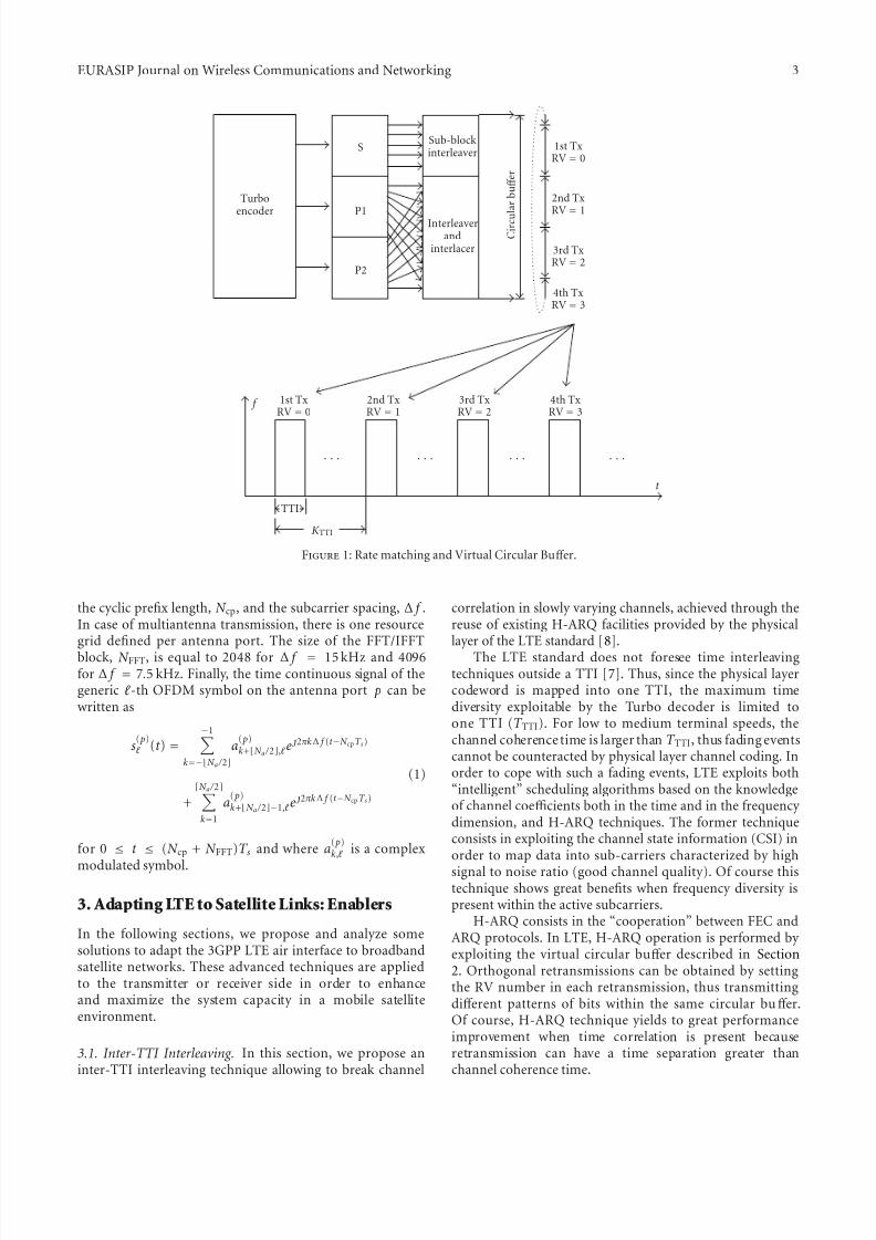
varying form K TC = 40 up to K TC = 6144. After channelencoding, the Circular Buff er (CB) and Rate Matching (RM)block allows to interleave, collect and select the three inputstreams coming from the Turbo encoder (systematic bits,parity sequence from encoder-1 and encoder-2), as depictedin Figure 1. The three input streams are processed with thefollowing steps.
(1) Each of the three streams is interleaved separately by a sub-block interleaver.
(2) The interleaved systematic bits are written into thebuff er in sequence, with the first bit of the interleavedsystematic bit stream at the beginning of the buff er.
(3) The interleaved P1 and P2 streams are interlacedbit by bit. The interleaved and interlaced parity bitstreams are written into the buff er in sequence, withthe first bit of the stream next to the last bit of theinterleaved systematic bit stream.
(4) Eight diff erent Redundancy Versions (RVs) are
defined, each of which specifies a starting bit index inthe buff er. The transmitter reads a block of coded bitsfrom the buff er, starting from the bit index specifiedby a chosen RV. For a desired code rate of operation,the number of coded bits N data to be selected fortransmission is calculated and passed to the RMblock as an input. If the end of the buff er is reachedand more coded bits are needed for transmission,the transmitter wraps around and continues at thebeginning of the buff er, hence the term of “circularbuff er.” Therefore, puncturing, and repetition can beachieved using a single method.
The CB has an advantage in flexibility (in code ratesachieved) and also granularity (in stream sizes). In LTE, theencoded and interleaved bits after the RM block are mappedinto OFDM symbols. The time unit for arranging the ratematched bits is the Transmission Time Interval (TTI).
Throughout all LTE specifications, the size of variousfields in the time domain is expressed as a number of timeunits, T s = 1 / (15000 × 2048) seconds. Both downlink anduplink transmissions are organized into radio frames withduration T f = 307200T s = 10 ms. In the following, theType-1 frame structure, applicable to both FDD and TDDinterface, is considered. Each radio frame consists of 20 slotsof length T slot = 15360T s = 0.5 ms, numbered from 0 to 19.A sub-frame is defined as two consecutive slots, where sub-
frame i consists of slots 2i and 2i + 1. A TTI corresponds toone sub-frame.
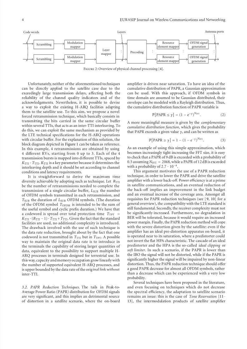
In general, the baseband signal representing a downlinkphysical channel is built through the following steps:
(i) scrambling of coded bits in each of the code words tobe transmitted on a physical channel;
(ii) modulation of scrambled bits to generate complex-valued modulation symbols;
(iii) mapping of the complex-valued modulation symbolsonto one or several transmission layers;
(iv) pre-coding of the complex-valued modulation sym-
bols on each layer for transmission on the antennaports;
(v) mapping of complex-valued modulation symbols foreach antenna port to resource elements;
(vi) generation of complex-valued time-domain OFDMsignal for each antenna port.
These operations are depicted and summarized in Figure 2.The details and implementation aspects of each block canbe extracted from [4]. The transmitted signal in each slot ismapped onto a resource grid of N a active subcarriers (fre-quency domain) and N symb OFDM symbols (time domain).The number of OFDM symbols in a slot, N symb, depends on
EURASIP Journal on Wireless Communications and Networking 3
Sub-blockinterleaver
Interleaverand
interlacer
1st TxRV = 0
2nd TxRV = 1
3rd TxRV = 2
4th TxRV = 3
C i r c u
l a r
b u ff e r
Turbo
encoder
S
P1
P2
1st TxRV = 0
2nd TxRV = 1
3rd TxRV = 2
4th TxRV = 3
t
f
K TTI
TTI
· · · · · · · · · · · ·
Figure 1: Rate matching and Virtual Circular Buff er.
the cyclic prefix length, N cp, and the subcarrier spacing, Δ f .In case of multiantenna transmission, there is one resourcegrid defined per antenna port. The size of the FFT/IFFTblock, N FFT, is equal to 2048 for Δ f = 15 kHz and 4096for Δ f = 7.5 kHz. Finally, the time continuous signal of thegeneric -th OFDM symbol on the antenna port p can bewritten as
s( p) (t ) =
−1k=−N a / 2
a( p)k+N a / 2, e
j2πkΔ f (t −N cpT s)
+N a / 2k=1
a( p)k+N a / 2−1, e
j2πkΔ f (t −N cpT s)
(1)
for 0 ≤ t ≤ (N cp + N FFT)T s and where a( p)k, is a complex
modulated symbol.
3. Adapting LTE to Satellite Links: Enablers
In the following sections, we propose and analyze somesolutions to adapt the 3GPP LTE air interface to broadbandsatellite networks. These advanced techniques are appliedto the transmitter or receiver side in order to enhanceand maximize the system capacity in a mobile satelliteenvironment.
3.1. Inter-TTI Interleaving. In this section, we propose aninter-TTI interleaving technique allowing to break channel
correlation in slowly varying channels, achieved through thereuse of existing H-ARQ facilities provided by the physicallayer of the LTE standard [8].
The LTE standard does not foresee time interleavingtechniques outside a TTI [7]. Thus, since the physical layercodeword is mapped into one TTI, the maximum timediversity exploitable by the Turbo decoder is limited toone TTI (T TTI). For low to medium terminal speeds, thechannel coherence time is larger than T TTI, thus fading eventscannot be counteracted by physical layer channel coding. Inorder to cope with such a fading events, LTE exploits both“intelligent” scheduling algorithms based on the knowledgeof channel coefficients both in the time and in the frequency dimension, and H-ARQ techniques. The former techniqueconsists in exploiting the channel state information (CSI) inorder to map data into sub-carriers characterized by high
signal to noise ratio (good channel quality). Of course thistechnique shows great benefits when frequency diversity ispresent within the active subcarriers.
H-ARQ consists in the “cooperation” between FEC andARQ protocols. In LTE, H-ARQ operation is performed by exploiting the virtual circular buff er described in Section2. Orthogonal retransmissions can be obtained by settingthe RV number in each retransmission, thus transmittingdiff erent patterns of bits within the same circular buff er.Of course, H-ARQ technique yields to great performanceimprovement when time correlation is present becauseretransmission can have a time separation greater thanchannel coherence time.
4 EURASIP Journal on Wireless Communications and Networking
OFDM signal
generationResource
element mapper
Precoding
Layers Antenna portsCode words
Scrambling
Scrambling
Layermapper
Modulation
mapper
Modulation
mapper
Resource
element mapper
OFDM signal
generation
Figure 2: Overview of physical channel processing [4].
Unfortunately, neither of the aforementioned techniquescan be directly applied to the satellite case due to theexceedingly large transmission delays, aff ecting both thereliability of the channel quality indicators and of theacknowledgements. Nevertheless, it is possible to devisea way to exploit the existing H-ARQ facilities adaptingthem to the satellite use. To this aim, we propose a novelforced retransmission technique, which basically consists in
transmitting the bits carried in the same circular buff
erwithin several TTIs, that acts as an inter-TTI interleaving. Todo this, we can exploit the same mechanism as provided by the LTE technical specifications for the H-ARQ operationswith circular buff er. For the explanation of this solution, theblock diagram depicted in Figure 1 can be taken as reference.In this example, 4 retransmissions are obtained by using4 diff erent RVs, starting from 0 up to 3. Each of the 4transmission bursts is mapped into diff erent TTIs, spaced by K TTI · T TTI. K TTI is a key parameter because it determines theinterleaving depth and it should be set according to channelconditions and latency requirements.
It is straightforward to derive the maximum time
diversity achievable by adopting such as technique. Let RTTIbe the number of retransmissions needed to complete thetransmission of a single circular buff er, LSUB the numberof OFDM symbols transmitted in each retransmission, andT SUB the duration of LSUB OFDM symbols. (The durationof the OFDM symbol T OFDM is intended to be the sum of the useful symbol and cyclic prefix duration.) We have thata codeword is spread over total protection time T TPT =
K TTI · (RTTI −1) ·T TTI +T TTI. Given the fact that the standardfacilities are used, no additional complexity is introduced.The drawback involved with the use of such technique isthe data rate reduction, brought about by the fact that onecodeword is not transmitted in T TTI but in T TPT. A possibleway to maintain the original data rate is to introduce inthe terminals the capability of storing larger quantities of data, equivalent to the possibility to support multiple H-ARQ processes in terminals designed for terrestrial use. Inthis way, capacity andmemory occupation grow linearly withthe number of supported equivalent H-ARQ processes, andis upper bounded by the data rate of the original link withoutinter-TTI.
3.2. PAPR Reduction Techniques. The tails in Peak-to-Average Power Ratio (PAPR) distribution for OFDM signalsare very significant, and this implies an detrimental sourceof distortion in a satellite scenario, where the on-board
amplifier is driven near saturation. To have an idea of thecumulative distribution of PAPR, a Gaussian approximationcan be used. With this approach, if OFDM symbols intime domain are assumed to be Gaussian distributed, theirenvelope can be modeled with a Rayleigh distribution. Thus,the cumulative distribution function of PAPR variable is
PPAPR ≤ γ
= (1 − e−γ)
N FFT . (2)
A more meaningful measure is given by the complementary cumulative distribution function, which gives the probability that PAPR exceeds a given value γ, and can be written as
PPAPR ≥ γ
= 1 − (1 − e−γ)
N FFT . (3)
As an example of using this simple approximation, whichbecomes increasingly tight increasing the FFT size, it is easy to check that a PAPR of 9 dB is exceeded with a probability of 0.5 assuming N FFT = 2048, while a PAPR of 12 dB is exceededwith a probability of 2.7 · 10−4.
This argument motivates the use of a PAPR reductiontechnique, in order to lower the PAPR and drive the satelliteamplifier with a lower back-off . Power efficiency is at a primein satellite communications, and an eventual reduction of the back-off implies an improvement in the link budgetand an eventual increase of the coverage area. Amongst allrequisites for PAPR reduction techniques (see [9, 10] for ageneral overview), the compatibility with the LTE standard isstill fundamental. Secondly, the receiver complexity must notbe significantly increased. Furthermore, no degradation inBER will be tolerated, because it would require an increasedpower margin. Finally, the PAPR reduction method will copewith the severe distortion given by the satellite: even if theamplifier has an ideal pre-distortion apparatus on-board, itis operated near to its saturation, where a predistorter couldnot invert the flat HPA characteristic. The cascade of an ideal
predistorter and the HPA is the so-called ideal clipping orsoft limiter . In such a scenario, if the PAPR is lower thanthe IBO the signal will not be distorted, while if the PAPR issignificantly higher the signal will be impaired by non-lineardistortion. Thus, the PAPR reduction technique should off era good PAPR decrease for almost all OFDM symbols, ratherthan a decrease which can be experienced with a very lowprobability.
Several techniques have been proposed in the literature,and even focusing on techniques which do not decreasethe spectral efficiency, the adaptation to satellite scenarioremains an issue: this is the case of Tone Reservation [11–13], the intermodulation products of satellite amplifier
EURASIP Journal on Wireless Communications and Networking 5
prevent using this technique, while it is very popular inthe wired scenario and when the amplifier is closer to itslinear region. The Selected Mapping technique [14, 15],although easy and elegant, needs a side information at thereceiver. The side information can be avoided, at expenseof a significant computational complexity increase at the
receiver. Companding techniques (see [10] and referencestherein) off er a dramatic reduction in PAPR and do notrequire complex processing. On the other hand, there is anoise enhancement, which turns out to be an importantsource of degradation at the very low SNRs used in satellitecommunications.
The Active Constellation Extension (ACE) technique [16]fulfills those requirements, moreover the power increasedue to PAPR reduction is exploited efficiently, obtaining anadditional margin against noise. The ACE approach is basedon the possibility to dynamically extend the position of someconstellation points in order to reduce the peaks of the timedomain signal (due to a constructive sum of a subset of the frequency domain data) without increasing Error Rate:the points are distanced from the borders of their Voronoiregions. The extension is performed iteratively, according tothe following procedure.
(1) Start with the frequency domain representation of aOFDM symbol.
(2) Convert into the time-domain signal, and clip allsamples exceeding a given magnitude V clip. If nosample is clipped, then exit.
(3) Reconvert into the frequency domain representationand restore all constellation points which have beenmoved towards the borders of their Voronoi regions.
(4) Go back to 2 until a fixed number of iteration isreached.
This algorithm is applied to data carriers only, excludingthus pilots, preamble/signalling and guard bands. In theperformance evaluation of the algorithm, the amplitudeclipping value is expressed in term of the correspondingPAPR, which is called PAPR-Target in the following.
The most critical point of this method is the choice of theclipping level V clip: a large value for V clip (which correspondstoan high PAPR-Target ) will yield a negligible power increaseand a poor convergence, since signal is unlikely to be clipped.On the opposite extreme, a very low clipping level will yield
again a poor convergence and a negligible power increase.In fact, considering the above algorithm, almost all pointswill be moved by clipping in step-2 and then restored by theconstellation constraint enforcing in step-3. A compromisevalue, which will lead to a PAPR around 5 or 6 dB is advisable, yielding a good convergence and a slight energy increase,due to the eff ectiveness of the extension procedure. Althoughthere are other ACE strategies [16], the solution presentedhere is attractive because it can be easily implemented bothin hardware and software, as reported in [17].
3.3. Random Access Signal Detection. The Random AccessChannel (RACH) is a contention-based channel for initial
uplink transmission, that is, from mobile user to base station.While the Physical RACH (PRACH) procedures as definedin the 3G systems are mainly used to register the terminalafter power-on to the network, in 4G networks, PRACH is incharge of dealing with new purposes and constraints. In anOFDM based system, in fact, orthogonal messages have to be
sent, thus the major challenge in such a system is to maintainuplink orthogonality among users. Hence both frequency and time synchronization of the transmitted signals fromthe users are needed. A downlink broadcast signal can besent to the users in order to allow a preliminary timing andfrequency estimation by the mobile users, and, accordingly a timing and frequency adjustment in the return link. Theremaining frequency misalignment is due to Doppler eff ectsand cannot be estimated nor compensated. On the otherhand, the fine timing estimation has to be performed by the base station when the signals coming from users aredetected. Thus, the main goal of PRACH is to obtain finetime synchronization by informing the mobile users howto compensate for the round trip delay. After a successfulrandom access procedure, in fact, the base station and themobile user should be synchronized within a fraction of theuplink cyclic prefix. In this way, the subsequent uplink signalscould be correctly decoded and would not interfere withother users connected to the network.
PRACH procedure in 4G systems consists in the trans-mission of a set of preambles, one for mobile user, inorder to allocate diff erent resources to diff erent users. Inorder to reduce collision probability, in the LTE standard,Zadoff -Chu (ZC) sequences [18], known also as a ConstantAmplitude Zero Autocorrelation (CAZAC) sequences, areused as signatures between diff erent use, because of the goodcorrelation properties. The ZC sequence obtained from theu-th root is defined by
xu(n) = exp− j(πun(n+1) /N ZC) 0 ≤ n ≤ N ZC − 1, (4)
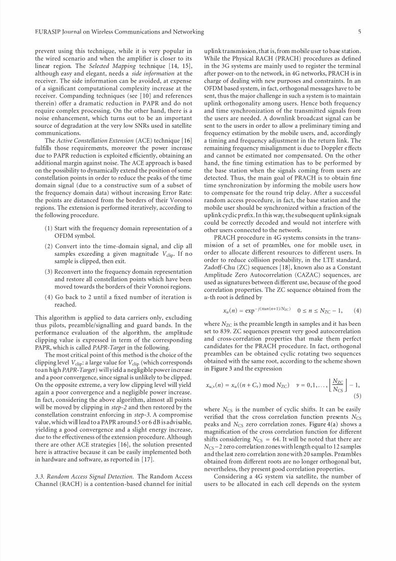
where N ZC is the preamble length in samples and it has beenset to 839. ZC sequences present very good autocorrelationand cross-correlation properties that make them perfectcandidates for the PRACH procedure. In fact, orthogonalpreambles can be obtained cyclic rotating two sequencesobtained with the same root, according to the scheme shownin Figure 3 and the expression
xu,ν(n) = xu((n + Cν) mod N ZC) ν = 0,1, . . . ,
N ZC
N CS
− 1,
(5)
where N CS is the number of cyclic shifts. It can be easily verified that the cross correlation function presents N CS
peaks and N CS zero correlation zones. Figure 4(a) shows amagnification of the cross correlation function for diff erentshifts considering N CS = 64. It will be noted that there areN CS−2 zero correlation zones with length equal to 12 samplesand the last zero correlation zone with 20 samples. Preamblesobtained from diff erent roots are no longer orthogonal but,nevertheless, they present good correlation properties.
Considering a 4G system via satellite, the number of users to be allocated in each cell depends on the system
Figure 4: Detection properties in the presence of interferers.
Table1: ZC allocation for GEO satellite scenario.
Cell Radius [km]Number of
root ZCsequences
Number of cyclic shift perroot sequence
150 (Near polar arctic circle) 64 1
300 (Near polar arctic circle) 64 1
500 (Near polar arctic circle) 64 1
150 (Europe) 64 1
300 (Europe) 64 1
500 (Europe) 64 1
150 (Tropical) 32 2
300 (Tropical) 64 1
500 (Tropical) 64 1
150 (Equator) 2 32
150 (Equator) 8 8
150 (Equator) 16 4
design. The zero correlation zone of the preambles has tobe larger then the maximum round trip propagation delay,depending on cell radius and multipath delay. The number of root ZC sequences and the number of cyclic shift sequencesdepend on cell radius and on the geographical position, andthey are reported in Table 1 for GEO satellites. Note that
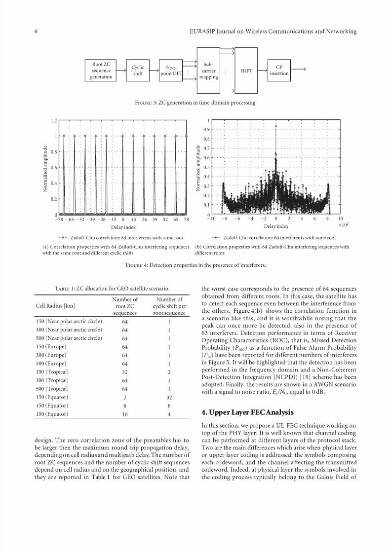
the worst case corresponds to the presence of 64 sequencesobtained from diff erent roots. In this case, the satellite hasto detect each sequence even between the interference fromthe others. Figure 4(b) shows the correlation function ina scenario like this, and it is worthwhile noting that thepeak can once more be detected, also in the presence of 63 interferers. Detection performance in terms of ReceiverOperating Characteristics (ROC), that is, Missed DetectionProbability (P md) as a function of False Alarm Probability (P fa) have been reported for diff erent numbers of interferersin Figure 5. It will be highlighted that the detection has beenperformed in the frequency domain and a Non-CoherentPost-Detection Integration (NCPDI) [19] scheme has been
adopted. Finally, the results are shown in a AWGN scenariowith a signal to noise ratio, Es /N 0, equal to 0 dB.
4. Upper Layer FEC Analysis
In this section, we propose a UL-FEC technique working ontop of the PHY layer. It is well known that channel codingcan be performed at diff erent layers of the protocol stack.Two are the main diff erences which arise when physical layeror upper layer coding is addressed: the symbols composingeach codeword, and the channel aff ecting the transmittedcodeword. Indeed, at physical layer the symbols involved inthe coding process typically belong to the Galois Field of
EURASIP Journal on Wireless Communications and Networking 7
10−6 10−5 10−4 10−3 10−2 10−1 100
False alarm probability
10−6
10−5
10−4
10−3
10−2
10−1
100
M i s s e d d e t e c t i o
n p r o
b a
b i l i t y
0 interfering root sequences, no impairments
31 interfering root sequences, no impairments
63 interfering root sequences, no impairments
Figure 5: ROC in AWGN channel with Es /N 0 = 0.0 dB withoutinterference, and with interferers with diff erent roots.
order m, GF (m). Nevertheless, also non binary codes can beadopted. Working at upper layer each symbol composing theUL codeword can be made up of packets of bits, dependingon the application level.
In order to build the UL-FEC technique on solid ground,the design and analysis has been carried out starting fromthe Multi Protocol Encapsulation Forward Error CorrectionTechnique (MPE-FEC) adopted by the DVB-H standard[20], and successively enhanced and modified in the frame-
work of the DVB-SH [1] standardization group. With respectto the MPE-FEC approach, the implementation of the UL-FEC technique for this framework has required to adapt theparameter setting to the LTE physical layer configurations. Inthe following, we adopt this terminology:
(i) k: the UL block length, that is the number of systematic symbols to be encoded by the UL encoder
(ii) n: the UL codeword length, that is the number of ULsymbols produced by the UL encoder
(iii) k: the actual UL-FEC block length if zero-padding isapplied
(iv)n
: the actual UL-FEC codeword length if zero-padding and/or puncturing is applied
(v) N JCC: number of jointly coded channels at physicallayer
(vi) SJCC: size of each channel in bytes
(vii) SUL-CRC: size of the upper layer Cyclic Redundancy Check (CRC) in bytes
(viii) SPHY-CRC: size of the physical layer CRC in bytes
(ix) K PHY: physical layer block length in bytes.
As in MPE-FEC, we define the UL-FEC matrix as a matrixcomposed of a variable number of rows (n of rows) and n
columns. Each entry of the matrix is an UL-symbol, thatis, 1 byte. The first k columns represent the systematic partof the matrix and are filled with the systematic UL-symbolscoming from the higher level. The last n − k columns carry the redundancy data computed on the first k columns. It isworthwhile to notice that the n and k values depend on the
selected UL code rate only, while n of rows is a parameterchosen accordingly to the physical layer configuration andis set by using the following formula: n of rows = K PHY −
SPHY-CRC − N JCCSUL-CRC. As a consequence, the number of bytes available for each channel in a given UL-FEC matrixcolumn is SJCC = n of rows /N JCC. With this configuration,the following operations must be sequentially performed.
(1) The information data coming from higher layer arewritten columns-wise in the systematic data part of the UL-FEC matrix.
(2) A Reed-Solomon (RS) encoding (n, k) is performedon each row producing the redundancy part of theUL-FEC matrix.
(3) The data are transmitted column-wise.
(4) An UL-CRC is appended after each group of SJCC
bytes.
(5) Each group of K PHY = N JCC(SJCC + SUL-CRC) bytescomposes a physical layer information packet.
(6) The PHY-CRC is appended to each physical layerinformation packet according to the LTE specifica-tions [7].
For sake of simplicity, we adopt the same RS mother codeprovided in [20], which is an RS(255,191). The code rate of this mother code is 3/4. Further code rates can be achieved
by using padding or puncturing techniques. For instance,if a UL-FEC rate 1/2 is needed, zero-padding is performedover the last 127 columns of the systematic data part of theUL-FEC matrix, yielding to k = 64 and n = 128. Thechoice of this RS code allows fully compatibility with DVB-Hnetworks.
It is important to note how the application of the CRCat UL and physical layer has an impact on the overall systemperformance. To better evaluate this impact, we distinguishto study cases:
(i) Case-A: only the PHY-CRC is considered (SUL-CRC =
0). In this scenario, the receiver is not able to checkthe integrity of a single UL packet carried within
the same physical layer information packets. Thisbasically means that if error is detected in the physicallayer information packet, all UL packets will bediscarded;
(ii) Case-B: both PHY and UL CRC are applied.
It is quite obvious that Case-B outperforms Case-A. In fact,if only a small fraction of bits are wrong after physical layerdecoding, Case-B is able to discard only the UL packets inwhich erroneous bits are present, while Case-A discards allN JCC carried within the physical layer information packets.The price to pay is an increased overhead of Case-B withrespect to Case-A due to the extra CRC bits appended.
8 EURASIP Journal on Wireless Communications and Networking
At the receiver side, depending whether Case-A or Case-B is taken into account, CRC integrity must be performedat diff erent levels. If the Case-A is considered, only the CRCat physical layer determines the data reliability; whereas inthe Case-B, the PHY-CRC could be ignored and the datareliability is only determined by the UL-CRC. Then, the UL-
FEC matrix is filled with the reliable data. In particular, forthe Case-A an entire column is marked as reliable or notreliable, while in the Case-B the UL-FEC matrix columnscould be partially reliable. Finally, the RS(n, k) decoding isperformed on each row. If the number of reliable positionin a row is at least k, the decoder is able to successfully decode the received information, and all unreliable positionsare recovered.
The UL-FEC protection capability against burst of errorscan be characterized by the so-called Maximum TolerableBurst Length (MTBL) [21], which consists in the maximumtime protection that the UL-FEC technique can provide. TheMTBL depends on both UL-FEC parameters and PHY datarate. In our proposal one PHY information packet is mappedin one column of the UL-FEC matrix. Since we are dealingwith MDS codes, the decoder is able to successfully decodeif at least k columns are correctly received in the UL-FECmatrix. Thus, the MTBL is simply given by the time takenby transmitting n − k columns, that is, the duration of n − k information packets. The MTBL can be increasedby adopting a sliding encoding mechanism [22]. The slidingencoding is a UL interleaver mechanism: a UL-FEC encoderimplementing sliding encoding selects the k data columnsfrom a window (SW) among the UL-FEC matrices andspreads the n − k parity sections over the same window.Basically, the same eff ect could be obtained by first normally encoding SW frames and then interleaving sections amongthe encoded SW frames. The total protection time TPTUL
achievable at upper layer by means of such a technique isgiven by TPTUL = n · SW · T TTI.
5. Simulation Results
Here, we discuss separately the numerical results obtainedby implementing the solutions presented in Section 3. Thefollowing general assumptions have been considered duringthe implementation of all techniques.
The LTE transmitted signal occupies 5 MHz of band-width, N a = 300, located in S-band (central frequency
f 0 = 2 GHz), the sub-carrier spacing is Δ f = 15 kHz, andFFT/IFFT size is fixed to N FFT = 2048. The long cyclic prefixis assumed, N cp = 512, thus N symb = 12 OFDM symbolsare transmitted in each TTI. The resulting OFDM symbolsduration is T ofdm = 83.33 μs, including the cyclic prefixduration of T cp = 16.67 μs.
5.1. Inter-TTI Improvements. For evaluating the inter-TTIproposal, the turbo encoder is fed with 2496 informationbits, while the circular buff er size is assumed to be 6300, thusresulting in an actual system code rate equal to R 2 / 5. Allsimulations have considered QPSK modulation.
0 2 4 6 8 10 12 14 16
Eb /N 0 (dB)
10−4
10−3
10−2
10−1
100
B L E R
NO inter-TTI
Inter-TTI, LSUB = 1, K TTI = 4
Inter-TTI, LSUB = 3, K TTI = 4
Inter-TTI, LSUB = 1, K TTI = 8
Inter-TTI, LSUB = 3, K TTI = 8
Inter-TTI, LSUB = 1, K TTI = 16Inter-TTI, LSUB = 3, K TTI = 16
Figure 6: BLER versus Eb /N 0. Terminal speed is equal to 30 km/h.
Figure 6 shows the block error rate (BLER) performanceversus Eb /N 0, with Eb being the energy per informationbit and N 0 the one-sided noise power spectral density. Thecurves refer to a user terminal speed of 30 km/h. The solidline curves represent the cases in which the number of transmitted OFDM symbols for each retransmission (LSUB)is 1, resulting in a total number of retransmissionsRTTI = 12,while the dashed line curves depict the case with LSUB = 3and RTTI = 4. In these configurations, we set the value of K TTI such that the total protection time T TTI is larger than
the channel coherence time T c, which for these simulationsis about T c 9 ms. (This is the coherence time of the smallscale fluctuations, and it depends directly from the terminalspeed and the central carrier frequency.) In particular, thesimulated values K TTI are 4, 8, 16. As it can be observed,the solid line curves always outperform the dashed line ones.This is easily explained considering the diff erent diversity granularity: in the case of LSUB = 1, each OFDM symbolis transmitted in a separated TTI. Therefore, the codewordspanned over the 12 OFDM symbols composing the entireTTI can benefit of diversity degree equal to 12. On the otherhand, if the case of LSUB = 3 is considered, the degreediversity is reduced to 4. It is worthwhile to note the large
performance enhancement yielded by the adoption of theinter-TTI technique. For instance, looking at Figure 6, theperformance gain at BLER = 10−3 increases up to 6 dB inthe case of LSUB = 1, and up to 4 dB considering LSUB = 3.
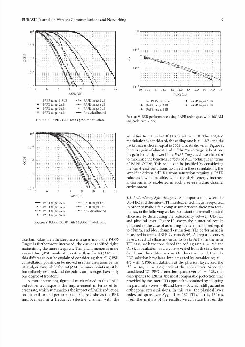
5.2. ACE Performance. The results of the ACE algorithm forPAPR reduction are discussed. First of all, the CCDF of PAPRdistribution have been analyzed for verifying theeff ectivenessof the selected method.
Figures 7 and 8 show PAPR distribution for QPSKand 16QAM, respectively. As it can be seen, if the PAPR-Target is too low, the CCDF curve has a poor slope.Increasing the PAPR-Target , the curve is shifted left until
EURASIP Journal on Wireless Communications and Networking 9
5 6 7 8 9 10 11 12
PAPR (dB)
10−4
10−3
10−2
10−1
100
C C D F
PAPR target 1.5 dB
PAPR target 2dB
PAPR target 3dB
PAPR target 4dB
PAPR target 5dB
PAPR target 6dB
PAPR target 7dB
Analytical bound
Figure7: PAPR CCDF with QPSK modulation.
5 6 7 8 9 10 11 12
PAPR (dB)
10−4
10−3
10−2
10−1
100
C C D F
PAPR target 2dB
PAPR target 3dB
PAPR target 4dB
PAPR target 5dB
PAPR target 6dB
PAPR target 7dB
Analytical bound
Figure 8: PAPR CCDF with 16QAM modulation.
a certain value, then the steepness increases and, if the PAPR-
Target is furthermore increased, the curve is shifted right,maintaining the same steepness. This phenomenon is moreevident for QPSK modulation rather than for 16QAM, andthis diff erence can be explained considering that all QPSKconstellation points can be moved in some directions by theACE algorithm, while for 16QAM the inner points must beimmediately restored, and the points on the edges have only one degree of freedom.
A more interesting figure of merit related to this PAPRreduction technique is the improvement in terms of biterror rate, which summarizes the impact of PAPR reductionon the end-to-end performance. Figure 9 shows the BERimprovement in a frequency selective channel, with the
10 10.5 11 11.5 12 12.5 13 13.5 14 14.5 15
Eb /N 0 (dB)
10−3
10−2
10−1
100
B E R
No PAPR reduction
PAPR target 3dB
PAPR target 4dB
PAPR target 5 dB
PAPR target 6 dB
Figure 9: BER performance using PAPR techniques with 16QAM
and code-rate = 3/5.
amplifier Input Back-Off (IBO) set to 3 dB. The 16QAMmodulation is considered, the coding rate is r = 3 / 5, and thepacket size is chosen equal to 7552 bits. As shown in Figure 9,there is a gain of almost 0.5dB if the PAPR-Target is kept low;the gain is slightly lower if the PAPR Target is chosen in orderto maximize the beneficial eff ects of ACE technique in termsof PAPR CCDF. This result can be justified by consideringthe worst-case conditions assumed in these simulations: theamplifier driven 3 dB far from saturation requires a PAPRvalue as low as possible, while the slight energy increase
is conveniently exploited in such a severe fading channelenvironment.
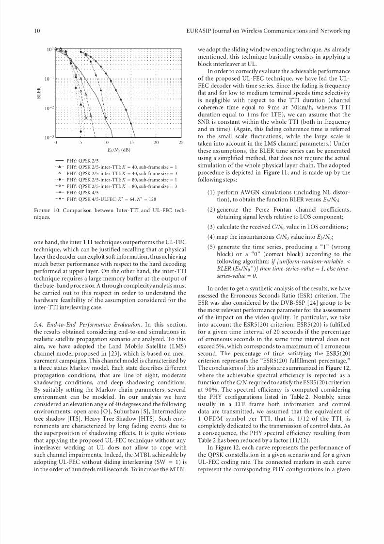
5.3. Redundancy Split Analysis. A comparison between theUL-FEC and the inter-TTI interleaver technique is reported.In order to make a fair comparison between these two tech-niques, in the following we keep constant the overall spectralefficiency by distributing the redundancy between UL-FECand physical layer. Figure 10 shows the numerical resultsobtained in the case of assuming the terminal speed equalto 3 km/h, and ideal channel estimation. The performance ismeasured in terms of BLER versus Eb /N 0. All reported curveshave a spectral efficiency equal to 4/5 bit/s/Hz. In the inter
TTI case, we have considered the coding rate r = 2 / 5 andQPSK modulation, and we have varied both the interleaverdepth and the subframe size. On the other hand, the UL-FEC solution have been implemented by considering r =
4 / 5 with QPSK modulation at the physical layer, and the(k = 64, n = 128) code at the upper layer. Since theconsidered UL-FEC protection spans over n = 128, thatcorresponds to 128 ms, the most comparable protection timeprovided by the inter-TTI approach is obtained by adoptingthe parametersK TTI = 40 and LSUB = 3, which still guaranteeorthogonal retrasmissions. In this case, the physical layercodeword spans over K TTI · 4 = 160 TTIs, that is, 160 ms.From the analysis of the results, we can state that on the
Figure 10: Comparison between Inter-TTI and UL-FEC tech-niques.
one hand, the inter TTI techniques outperforms the UL-FECtechnique, which can be justified recalling that at physicallayer the decoder can exploit soft information, thus achievingmuch better performance with respect to the hard decodingperformed at upper layer. On the other hand, the inter-TTItechnique requires a large memory buff er at the output of
the base-band processor. A through complexity analysis mustbe carried out to this respect in order to understand thehardware feasibility of the assumption considered for theinter-TTI interleaving case.
5.4. End-to-End Performance Evaluation. In this section,the results obtained considering end-to-end simulations inrealistic satellite propagation scenario are analyzed. To thisaim, we have adopted the Land Mobile Satellite (LMS)channel model proposed in [23], which is based on mea-surement campaigns. This channel model is characterized by a three states Markov model. Each state describes diff erentpropagation conditions, that are line of sight, moderate
shadowing conditions, and deep shadowing conditions.By suitably setting the Markov chain parameters, severalenvironment can be modeled. In our analysis we haveconsidered an elevation angle of 40 degrees and the followingenvironments: open area [O], Suburban [S], Intermediatetree shadow [ITS], Heavy Tree Shadow [HTS]. Such envi-ronments are characterized by long fading events due tothe superposition of shadowing eff ects. It is quite obviousthat applying the proposed UL-FEC technique without any interleaver working at UL does not allow to cope withsuch channel impairments. Indeed, the MTBL achievable by adopting UL-FEC without sliding interleaving (SW = 1) isin the order of hundreds milliseconds. To increase the MTBL
we adopt the sliding window encoding technique. As already mentioned, this technique basically consists in applying ablock interleaver at UL.
In order to correctly evaluate the achievable performanceof the proposed UL-FEC technique, we have fed the UL-FEC decoder with time series. Since the fading is frequency
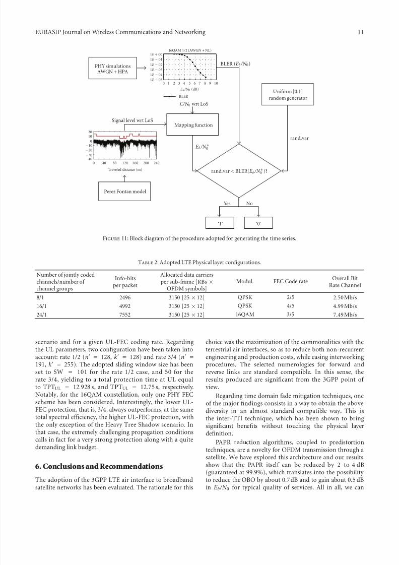
flat and for low to medium terminal speeds time selectivity is negligible with respect to the TTI duration (channelcoherence time equal to 9 ms at 30 km/h, whereas TTIduration equal to 1 ms for LTE), we can assume that theSNR is constant within the whole TTI (both in frequency and in time). (Again, this fading coherence time is referredto the small scale fluctuations, while the large scale istaken into account in the LMS channel parameters.) Underthese assumptions, the BLER time series can be generatedusing a simplified method, that does not require the actualsimulation of the whole physical layer chain. The adoptedprocedure is depicted in Figure 11, and is made up by thefollowing steps:
(1) perform AWGN simulations (including NL distor-tion), to obtain the function BLER versus Eb /N 0;
(2) generate the Perez Fontan channel coefficients,obtaining signal levels relative to LOS component;
(3) calculate the received C/N 0 value in LOS conditions;
(4) map the instantaneous C/N 0 value into Eb /N 0;
(5) generate the time series, producing a “1” (wrongblock) or a “0” (correct block) according to thefollowing algorithm: if [uniform-random-variable <BLER (Eb /N 0
∗)] then time-series-value = 1, else time-series-value = 0 .
In order to get a synthetic analysis of the results, we haveassessed the Erroneous Seconds Ratio (ESR) criterion. TheESR was also considered by the DVB-SSP [24] group to bethe most relevant performance parameter for the assessmentof the impact on the video quality. In particular, we takeinto account the ESR5(20) criterion: ESR5(20) is fulfilledfor a given time interval of 20 seconds if the percentageof erroneous seconds in the same time interval does notexceed 5%, which corresponds to a maximum of 1 erroneoussecond. The percentage of time satisfying the ESR5(20)criterion represents the “ESR5(20) fulfillment percentage.”The conclusions of this analysis are summarized in Figure 12,where the achievable spectral efficiency is reported as a
function of theC/N required to satisfy the ESR5(20) criterionat 90%. The spectral efficiency is computed consideringthe PHY configurations listed in Table 2. Notably, sinceusually in a LTE frame both information and controldata are transmitted, we assumed that the equivalent of 1 OFDM symbol per TTI, that is, 1/12 of the TTI, iscompletely dedicated to the transmission of control data. Asa consequence, the PHY spectral efficiency resulting fromTable 2 has been reduced by a factor (11/12).
In Figure 12, each curve represents the performance of the QPSK constellation in a given scenario and for a givenUL-FEC coding rate. The connected markers in each curverepresent the corresponding PHY configurations in a given
scenario and for a given UL-FEC coding rate. Regardingthe UL parameters, two configuration have been taken intoaccount: rate 1/2 (n = 128, k = 128) and rate 3/4 (n =
191, k = 255). The adopted sliding window size has beenset to SW = 101 for the rate 1/2 case, and 50 for therate 3/4, yielding to a total protection time at UL equalto TPTUL = 12.928 s, and TPTUL = 12.75 s, respectively.
Notably, for the 16QAM constellation, only one PHY FECscheme has been considered. Interestingly, the lower UL-FEC protection, that is, 3/4, always outperforms, at the sametotal spectral efficiency, the higher UL-FEC protection, withthe only exception of the Heavy Tree Shadow scenario. Inthat case, the extremely challenging propagation conditionscalls in fact for a very strong protection along with a quitedemanding link budget.
6. Conclusions and Recommendations
The adoption of the 3GPP LTE air interface to broadbandsatellite networks has been evaluated. The rationale for this
choice was the maximization of the commonalities with theterrestrial air interfaces, so as to reduce both non-recurrentengineering and production costs, while easing interworkingprocedures. The selected numerologies for forward andreverse links are standard compatible. In this sense, theresults produced are significant from the 3GPP point of view.
Regarding time domain fade mitigation techniques, oneof the major findings consists in a way to obtain the abovediversity in an almost standard compatible way. This isthe inter-TTI technique, which has been shown to bringsignificant benefits without touching the physical layerdefinition.
PAPR reduction algorithms, coupled to predistortiontechniques, are a novelty for OFDM transmission through asatellite. We have explored this architecture and our resultsshow that the PAPR itself can be reduced by 2 to 4 dB(guaranteed at 99.9%), which translates into the possibility to reduce the OBO by about 0.7dB and to gain about 0.5 dBin Eb /N 0 for typical quality of services. All in all, we can
expect a gain in total degradation around 1 dB, which iscertainly not negligible.
Regarding frame acquisition procedures, they are quitespecific for LTE air interface. The design of acquisition
sequences for 3GPP LTE has been performed adapting itto the diff erent requirements set by satellite transmissioninvolving the use of large geographic beams.
Additionally, in order to further extend the link reliability over the satellite link, the use of UL-FEC techniques has beeninvestigated. Simulation results clearly show that the UL-FEC technique is a very eff ective solution that can drastically improve the achievable block error rate and ESR5(20)performance.
In order to provide useful guidelines for the systemdesign, the analysis of the optimum redundancy splitbetween physical and upper layer coding has been per-formed. In this case, results show that in most cases it is
beneficial to limit the protection at physical layer in orderto ease channel estimation and to compensate the reducedperformance through a stronger UL coding. The rationalebehind this conclusion is that the UL-FEC benefits a largertime diversity thus performing significantly better than thephysical layer coding in almost all scenarios.
Acknowledgment
This work is supported in part by the ESA contract no.20194/06/NL/US, “Study of Satellite Role in 4G MobileNetworks.”
References
[1] ETSI EN 302 583, “Digital video broadcasting (DVB); framingstructure, channel coding and modulation for satellite servicesto handheld devices (SH) below 3 GHz,” v1.1.1, March 2008.
[2] The Integral Satcom Initiative (ISI), “ISI strategic researchagenda,” FP7 Technology Platform, v1.1, January 2006,
http://www.isi-initiative.eu.org/isi joomla.[3] ETSI TR 102 443, “Satellite earth stations and systems (SES);
satellite component of UMTS/IMT-2000; evaluation of theOFDM as a satellite radio interface,” v1.1.1, August 2008.
[4] 3GPP TS36.211, “3rd Generation Partnership Project; Techni-cal Specification Group Radio Access Network; Evolved Uni-versal Terrestrial Radio Access (E-UTRA); Physical Channelsand Modulation (Release 8),” v8.2.0, March 2008.
[5] “IEEE standard for local and metropolitan area networks,part 16: air Interface for fixed and mobile broadband wirelessaccess systems amendment 2: physical and medium accesscontrol layers for combined fixed and mobile operation inlicensed bands and corrigendum 1,” IEEE Computer Society and the IEEE Microwave Theory and Techniques Society, 20
February 2006.
[6] G. E. Corazza, P. Britten, I. Buret, et al., “Defining therole of satellite communications in 4G,” in Proceedings of the 8th World Wireless Congress on Fourth Generation MobileCommunications (WWC ’07), pp. 60–64, San Francisco, Calif,USA, May 2007.
[7] 3GPP TS36.212, “3rd Generation partnership project; techni-cal specification group radio access network; evolved universalterrestrial radio access (E-UTRA); multiplexing and channelcoding (release 8),” v8.2.0, March 2008.
[8] M. Papaleo, M. Neri, G. E. Corazza, and A. Vanelli-Coralli,“Using LTE in 4G satellite communications: increasing timediversity through forced retransmission,” in Proceedings of the10th International Workshop on Signal Processing for SpaceCommunications (SPSC ’08), Rhodes Island, Greece, October2008.
[9] S. H. Han and J. H. Lee, “An overview of peak-to-averagepower ratio reduction techniques for multicarrier transmis-sion,” IEEE Wireless Communications, vol. 12, no. 2, pp. 56–65,2005.
[10] T. Jiang and Y. Wu, “An overview: peak-to-average power ratioreduction techniques for OFDM signals,” IEEE Transactions onBroadcasting , vol. 54, no. 2, pp. 257–268, 2008.
[11] J. Tellado, Peak to average power reduction for multicarrier modulation, Ph.D. dissertation, Stanford University, Stanford,Calif, USA, 2000.
[12] B. S. Krongold and D. L. Jones, “An active-set approach for
OFDM PAR reduction via tone reservation,” IEEE Transactionson Signal Processing , vol. 52, no. 2, pp. 495–509, 2004.
[13] S. Janaaththanan, C. Kasparis, and B. G. Evans, “A gradientbased algorithm for PAPR reduction of OFDM using tonereservation technique,” in Proceedings of the 67th IEEE Vehic-ular Technology Conference (VTC ’08), pp. 2977–2980, MarinaBay, Singapore, May 2008.
[14] R. W. Bauml, R. F. H. Fischer, and J. B. Huber, “Reducingthe peak-to-average power ratio of multicarrier modulationby selected mapping,” Electronics Letters, vol. 32, no. 22, pp.2056–2057, 1996.
[15] M. Breiling, S. H. Mller-Weinfurtner, and J. B. Huber, “SMLpeak-power reduction without explicit side information,”IEEE Communications Letters, vol. 5, no. 6, pp. 239–241, 2001.
EURASIP Journal on Wireless Communications and Networking 13
[16] B. S. Krongold and D. L. Jones, “PAR reduction in OFDMvia active constellation extension,” IEEE Transactions onBroadcasting , vol. 49, no. 3, pp. 258–268, 2003.
[17] ETSI EN 302 755, “Digital video broadcasting (DVB); framestructure channel coding and modulation for a secondgeneration digital terrestrial television broadcasting system(DVB-T2),” April 2008.
[18] D. C. Chu, “Polyphase codes with good periodic correlationproperties,” IEEE Transactions on Information Theory , vol. 18,no. 4, pp. 531–532, 1972.
[19] A. J. Viterbi, CDMA Principles of Spread Spectrum Commu-nications, Addison-Wesley Wireless Communications Series,Addison-Wesley, Reading, Mass, USA, 2nd edition, 1995.
[20] ETSI TR 102 377, “Digital video broadcasting (DVB); DVB-Himplementation guidelines,” v1.2.1, November 2005.
[21] M. Papaleo, R. Firrincieli, S. Cioni, et al., “Link layer FEC inDVB-RCS: performance evaluation in nLoS conditions,” inProceedings of the 67th IEEE Vehicular Technology Conference(VTC ’08), pp. 2972–2976, Marina Bay, Singapore, May 2008.
[22] M. Papaleo, R. Firrincieli, G. E. Corazza, and A. Vanelli-Coralli, “On the application of MPE-FEC to mobile DVB-
S2: performance evaluation in deep fading conditions,” inProceedings of the International Workshop on Satellite and SpaceCommunication (IWSSC ’07), pp. 223–227, Salzburg, Austria,September 2007.
[23] F. Perez-Fontan,M.Vazquez-Castro,C. E. Cabado, J.P. Garcıa,and E. Kubista, “Statistical modeling of the LMS channel,”IEEE Transactions on Vehicular Technology , vol. 50, no. 6, pp.1549–1567, 2001.
[24] ETSI TM-SSP252-Revision 6 (2007-05), “Digital video broad-casting (DVB); DVB-SH implementation guidelines”.