27
NEC’s proposals for LTE Advanced NEC Corporation 7 th , 8 th April 2008 3GPP RAN IMT-Advanced Workshop REV- 080022
| Date post: | 11-Dec-2015 |
| Category: |
Documents |
| Upload: | rahul-deshwal |
| View: | 2 times |
| Download: | 0 times |
NEC’s proposals for LTE AdvancedNEC’s proposals for LTE Advanced
NEC Corporation
7th, 8th April 2008
3GPP RAN IMT-Advanced Workshop
REV-080022REV-080022
© NEC Corporation 2007 2
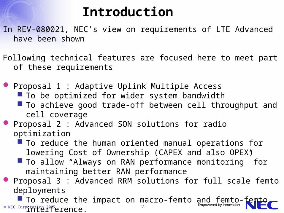
IntroductionIn REV-080021, NEC’s view on requirements of LTE Advanced have been
shown
Following technical features are focused here to meet part of these requirements
Proposal 1 : Adaptive Uplink Multiple Access To be optimized for wider system bandwidth To achieve good trade-off between cell throughput and cell coverage
Proposal 2 : Advanced SON solutions for radio optimization To reduce the human oriented manual operations for lowering Cost of
Ownership (CAPEX and also OPEX) To allow “Always on RAN performance monitoring” for maintaining better
RAN performance Proposal 3 : Advanced RRM solutions for full scale femto deployments
To reduce the impact on macro-femto and femto-femto interference.
© NEC Corporation 2007 3
LTE-Advanced Feature Proposal 1: Adaptive Uplink Multiple Access
© NEC Corporation 2007 4
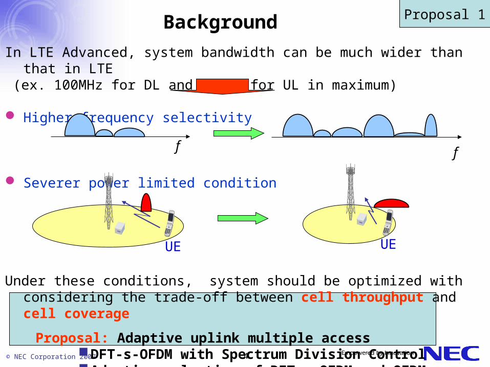
Background
In LTE Advanced, system bandwidth can be much wider than that in LTE (ex. 100MHz for DL and 50MHz for UL in maximum)
Higher frequency selectivity
Severer power limited condition
Under these conditions, system should be optimized with considering the trade-off between cell throughput and cell coverage
Proposal: Adaptive uplink multiple accessDFT-s-OFDM with Spectrum Division ControlAdaptive selection of DFT-s-OFDM and OFDM
f f
Proposal 1
UE UE

© NEC Corporation 2007 5
DFT-s-OFDM with SDC
• DFT-s-OFDM can generate both single carrier signal and multi-carrier signal
• LTE adopts single carrier generation only currently to achieve the lowest PAPR Restriction in resource allocation
Cell throughput can be maximized by controlling SD (Spectrum Division) considering trade-off between PAPR and resource allocation flexibility
+CP
f
f
SC-FDMA(SD=1)
MC-FDMA(SD=4)
IFFTDFTData Sub-carriermapping
Sub-carriermapping
Proposal 1

© NEC Corporation 2007 6
• PAPR increases gradually as SD (Spectrum Division) is getting larger.
• We can find UE-specific SD to satisfy different PAPR requirement.
PAPR of DFT-s-OFDM with SDC
DFT-s-OFDM
OFDM
f
f
SD=4
SD=2
QPSK
f
SD=1 ( SC-FDMA )
Proposal 1
© NEC Corporation 2007 7
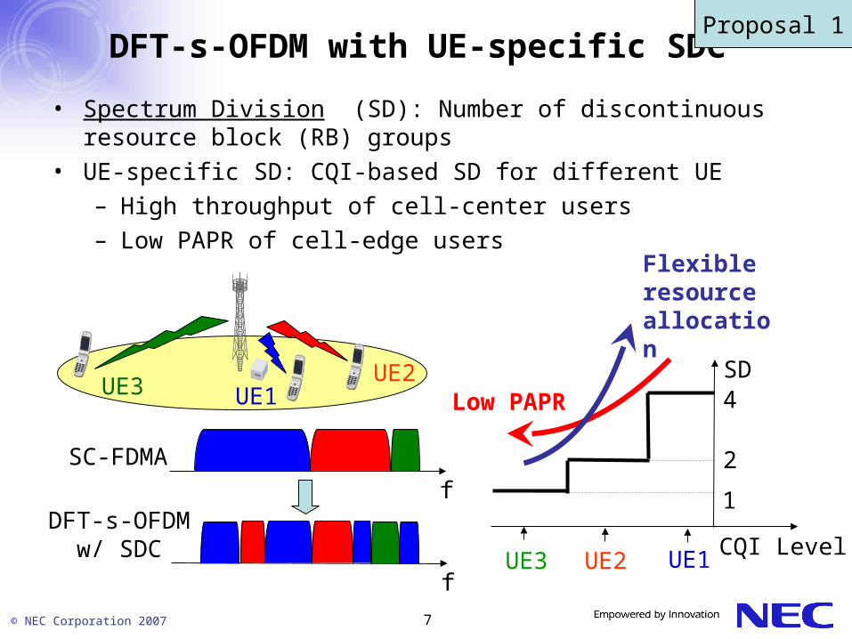
DFT-s-OFDM with UE-specific SDC
• Spectrum Division (SD): Number of discontinuous resource block (RB) groups
• UE-specific SD: CQI-based SD for different UE– High throughput of cell-center users– Low PAPR of cell-edge users
f
f
SC-FDMA
DFT-s-OFDM w/ SDC
SD
CQI Level
4
2
1
UE3 UE2 UE1
Low PAPR
Flexible resource allocation
Proposal 1
UE1UE2
UE3

© NEC Corporation 2007 8
Adaptive selection of DFT-s-OFDM / OFDMBase Station selects DFT-s-OFDM or OFDM depending on the cell size For Macro cell: DFT-s-OFDM (Wide coverage with low PAPR) For Micro/Femto cell: OFDM (Higher Peak Rate with MIMO)
Additional use of OFDM in cell center of Macro cell gives extra gain ⇒ UE specific(Hybrid)use of DFT-s-OFDM and OFDM could be applicable
Femto/Micro Cell:OFDM
Macro Cell:DFT-s-OFDM
On either cell specific or UE specific,tradeoff in Complexity and Throughput must be considered
Cell Specific
UE Specific(Hybrid)
Femto/Micro Cell:OFDM
Macro Cell:DFT-s-OFDM / OFDM
Proposal 1
OFDM
DFT-s-OFDM

© NEC Corporation 2007 9
SummaryThe followings have been proposed for LTE+ uplink access scheme to
achieve good trade-off between cell throughput and cell coverage
DFT-s-OFDM with SDC (Spectrum Division Control)Throughput optimization by CQI-based Spectrum Division for different
UELower SD for power limited UEs to achieve lower PAPRHigher SD for non-power limited UEs to achieve higher scheduling
flexibility
Adaptive selection between DFT-s-OFDM and OFDMCell specific selection
OFDM for small cell to maximize MIMO gainDFT-s-OFDM for large cell to maximize coverage
UE specific selection- Higher gain than cell specific one is expected, but actual gain
should be investigated- Increase of complexity by introducing UE specific adaptation should
be carefully investigated
Proposal 1

© NEC Corporation 2007 10NEC Confidential
LTE-Advanced Feature Proposal 2: Advanced SON solutions
for radio optimization = SONv2

© NEC Corporation 2007 11
Introduction: Self-X Radio Access Network
• Self-X RAN == More Intelligent RAN– Self Organizing based on PnP behavior– Self Optimizing based on always on monitoring– Self Coordinating based on distributed decision– Self Healing based on detection/reporting– …
• Why Self X Technologies?– Reduce the human oriented manual operations.
• Lowering Cost of Ownership (CAPEX and also OPEX)
– “Always on RAN performance monitoring”• Maintaining better RAN performance
Proposal 2
© NEC Corporation 2007 12
SON related Agreements in Release 8 Global Cell ID and Automatic Neighbor Search
Building up neighboring cell list ANR mechanism allows detection of missing neighbour relation
=> automatic optimization of the neighboring cell list
eNB measurements RACH access, DL/UL throughputs, RB utilizations
UE measurements Detected cells, Global cell ID
SON features in Release 8 provide a good starting point and more SON features are needed for LTE advanced systems.
LTE advanced should focus not only on L1 speed but also more advanced SON mechanisms
Release 8 SON FeaturesProposal 2

© NEC Corporation 2007 13
Example 1: Self-deployment of eNodeBs
• More autonomous deployment becomes obviously more interesting – Without planning of radio parameters– Also useful study item for home NodeB deployment
• Start with minimal coverage and gradually increase cell size• Radio scanning to find unused resources• Negotiation with neighbor cells about spectrum resource usage
Resource negotiations
Proposal 2
© NEC Corporation 2007 14
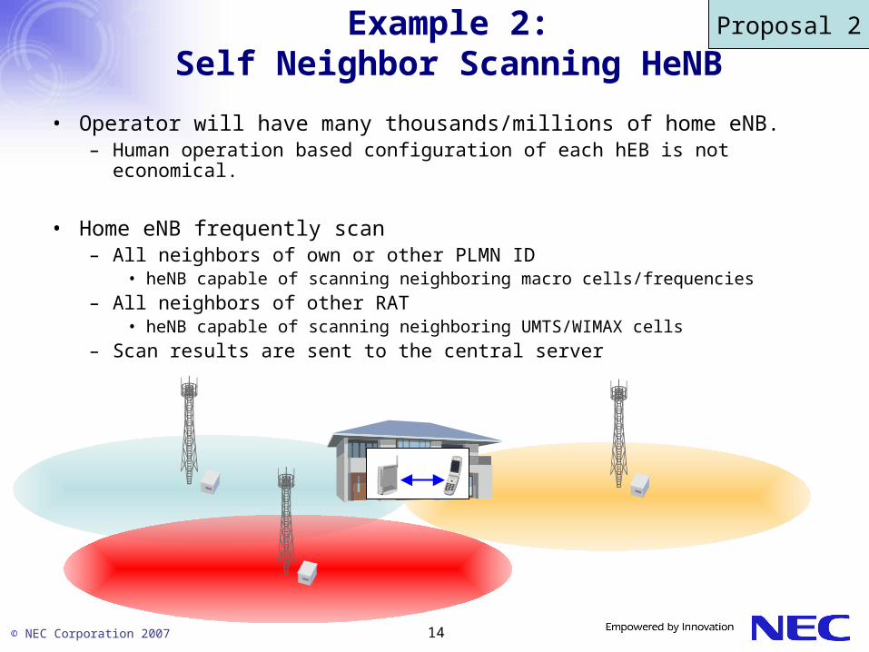
Example 2: Self Neighbor Scanning HeNB
• Operator will have many thousands/millions of home eNB.– Human operation based configuration of each hEB is not economical.
• Home eNB frequently scan – All neighbors of own or other PLMN ID
• heNB capable of scanning neighboring macro cells/frequencies
– All neighbors of other RAT• heNB capable of scanning neighboring UMTS/WIMAX cells
– Scan results are sent to the central server
Proposal 2

© NEC Corporation 2007 15
Example 3: Self Coordinating Interference Management
time
frequency
Slots that are not to be used for high power transmission in blue cell
• To coordinate scheduling in interfering cells, – Alt1: Semi-static restrictions for users close to cell borders
• Self coordination between cells set by rules • Agreed in Release 8 as HII
– Alt2: Short time-scale coordination • Very high speed of coordination for re-optimization based on load in different cells
X2 based Standardized RRMProcedures
Proposal 2

© NEC Corporation 2007 16
Example 4: HO Parameterization Optimization
• Handover parameter optimization triggered by “performance problems”
• Optimization of individual neighbor-to-neighbor parameters– E.g. HO hysterisis control
• Slow optimization loop – Cautiously change parameter to avoid user perceivable degradation– Evaluate results through performance monitoring
Reporting of Radio Link Failure with Location
Proposal 2

© NEC Corporation 2007 17
Example 5: UE Measured Performance Reporting
• Real performance based UE’s reporting of poor user experiences – For example, very low throughput reporting (below 64kbps at location X,Y)
• Problem analysis– Drawing the real performance map over X days or Y weeks.
• RAN parameters– Antenna tilt, TX power, Scheduler parameters, …
• Slow optimization loop – Cautiously change RAN parameters to avoid user perceivable degradation
Reporting of Very Low Throughputwith Location Info
Proposal 2

© NEC Corporation 2007 18
Example 6: Common Channel Self Optimization
RACH, PCH, BCH Power optimizations• Instead of drive tests: slow optimization based on UE reports
– received signal strength, channel quality, neighbor signal strength
– Ideally also location of UE
• Cautious adjustment of power in one cell, monitoring of effects– search optimal settings, e.g. gradient descent
Proposal 2

© NEC Corporation 2007 19
Example 7: Reduction of Energy Consumption by RAN
• Partial or complete eNB power down during low load, e.g. at night
• Stored profiles used to reconfigure radio parameters for the new topology
• Wake up based on timers or external triggers
• Question: would operators be interested in solutions that close down an eNB?
Proposal 2

© NEC Corporation 2007 20
Summary of Proposal 2: SONv2 for LTE Advanced
• 7 examples of SONv2 are presented that can reduce the cost of ownership of LTE advanced system.
• Clear work split between RAN and SA groups – i.e. RAN related parameters & mechanisms to be
handled by RAN groups.
Self Deployable Cell
HO failure reporting with location info
Automatic Common Channel Power
Control
Very low throughput reporting with location
info.
Configurationprofiles
O&M
Measurement data
Always on RAN performance
monitoring based on BTS and MS reporting.
Proposal 2

© NEC Corporation 2007 21
LTE-Advanced Feature Proposal 3: Several Issues and Challenges
for the Future Full Scale Femto Deployment

© NEC Corporation 2007 22
Advantages in Femto cell deployment in a Radio Aspect
• Providing very high throughput for indoor users• Extending indoor coverage • Increasing radio capacity in an outdoor and indoor environment
Macro NodeB
Outdoor UE
Indoor UE
Macro NodeB Home
NodeB
Outdoor UE
Indoor UE
Before introducing femto Cells
After introducing femto Cells
0200400600800100012001400160018002000
0 400 800 1200 1600 2000システムスループット [kbps]
ユー
ザス
ルー
プッ
ト [kbps]
Indoor
1MbpsBefore introducing femto cells
Cell ThroughputHSDPA User Throughput
After introducing femto cells
Outdoor
Example: User throughput of HSDPA (Category6) at 1 Mbps of cell throughput will increase by 1.3 and 2.3 times in an outdoor and indoor environment respectively.
Proposal 3

© NEC Corporation 2007 23
Macro NodeB
Femto NodeB
Macro UE
Femto UE
Desired signal
3. DL interference from Macro NodeB to Femto UE
1. DL interference from Femto NodeB
to Macro UE
4. UL interference from Femto UE to Macro
NodeB
2. UL interference from Macro UE to
Femto NodeB
5. DL interference from Femto NodeB to Femto UE in another femto cell
6. UL interference from Femto UE to Femto NodeB
in another femto cell
Desired signal
Interference Scenarios
The impact of interference will depend on the following:• Radio frequency (same as or different from that of macro NodeBs) • Maximum or CPICH transmission power of Home NodeB (fixed or adaptive)• Indoor environment condition• The number of Home NodeBs per macro cell• Access to Home NodeBs (open or closed)
There are 6 interference scenarios between macro and femto cells or among femto cells, which may minimize the femto cell advangtages.
Proposal 3

© NEC Corporation 2007 24
RF Selection
• Purpose:To avoid the mutual interference between femto cells and macro
or micro cells • Solution:
RF is selected for Home NodeBs based on CPICH RSCP measured at Home NodeBs and cell information such as HCS or CPICH Tx Power.
• If there is a RF whose CPICH RSCP is below a certain level, then a femto cell selects that RF
• Oherwise, a femto cell selects RF which has lowest HCS or largest CPICH Tx Power.
Macro Cell : RF1Micro Cell : RF2
Conventional: RF2 is selected because of lower CPICH RSCP, leading to increasing the interference.Proposal: RF1 is selected because of lower HCS, leading to avoiding the interference.
Assumptions at this example:-Femto cell is in a micro cell-CPICH RSCP: RF1 > RF2 -HCS: RF1 < RF2- (CPICH Tx Power: RF1 > RF2 )
Proposal 3

© NEC Corporation 2007 25
Technical challenges to solve the interference issues
• Home NodeBs are required to function as minimizing the interference in the self-organizing way.
• For example, the following technical solutions to minimize the interference between macro and femto cells ( from 1 to 4 at the previous page) can be considered. RF selection for femto cell Maximum or CPICH transmission power control of femto cell
considering indoor environment conditions
Proposal 3

© NEC Corporation 2007 26
Summary
• RF-related technical subjects and the interference mitigation scenarios for 3G Home NodeB are described.
• It is necessary to study techniques for minimizing the interference which can cause the degradation of indoor coverage or radio capacity of macro or femto cells.
Proposal 3

© NEC Corporation 2007 27


